EP2942797A1 - A reinforced magnet - Google Patents
A reinforced magnet Download PDFInfo
- Publication number
- EP2942797A1 EP2942797A1 EP15166140.2A EP15166140A EP2942797A1 EP 2942797 A1 EP2942797 A1 EP 2942797A1 EP 15166140 A EP15166140 A EP 15166140A EP 2942797 A1 EP2942797 A1 EP 2942797A1
- Authority
- EP
- European Patent Office
- Prior art keywords
- magnet
- coil
- composite body
- binder
- reinforcing elements
- Prior art date
- Legal status (The legal status is an assumption and is not a legal conclusion. Google has not performed a legal analysis and makes no representation as to the accuracy of the status listed.)
- Withdrawn
Links
- 239000002131 composite material Substances 0.000 claims abstract description 72
- 230000003014 reinforcing effect Effects 0.000 claims abstract description 52
- 239000011230 binding agent Substances 0.000 claims abstract description 50
- 239000006247 magnetic powder Substances 0.000 claims abstract description 18
- 238000004519 manufacturing process Methods 0.000 claims abstract description 15
- 239000000463 material Substances 0.000 claims description 16
- 239000000843 powder Substances 0.000 claims description 9
- 238000000034 method Methods 0.000 claims description 8
- 230000008901 benefit Effects 0.000 description 5
- 239000002184 metal Substances 0.000 description 5
- 229910052751 metal Inorganic materials 0.000 description 5
- 230000007423 decrease Effects 0.000 description 4
- 239000004020 conductor Substances 0.000 description 2
- 230000008602 contraction Effects 0.000 description 2
- 238000001746 injection moulding Methods 0.000 description 2
- 239000000155 melt Substances 0.000 description 2
- 150000002739 metals Chemical class 0.000 description 2
- 238000000465 moulding Methods 0.000 description 2
- 230000002787 reinforcement Effects 0.000 description 2
- 238000010008 shearing Methods 0.000 description 2
- OKTJSMMVPCPJKN-UHFFFAOYSA-N Carbon Chemical compound [C] OKTJSMMVPCPJKN-UHFFFAOYSA-N 0.000 description 1
- 239000000853 adhesive Substances 0.000 description 1
- 230000001070 adhesive effect Effects 0.000 description 1
- 239000004760 aramid Substances 0.000 description 1
- 229920003235 aromatic polyamide Polymers 0.000 description 1
- 229910052799 carbon Inorganic materials 0.000 description 1
- 238000005056 compaction Methods 0.000 description 1
- 238000000748 compression moulding Methods 0.000 description 1
- 238000001816 cooling Methods 0.000 description 1
- 239000008358 core component Substances 0.000 description 1
- 238000009826 distribution Methods 0.000 description 1
- 239000003365 glass fiber Substances 0.000 description 1
- 239000004033 plastic Substances 0.000 description 1
- 229920003023 plastic Polymers 0.000 description 1
- 238000005728 strengthening Methods 0.000 description 1
- 239000004634 thermosetting polymer Substances 0.000 description 1
Images



Classifications
-
- H—ELECTRICITY
- H01—ELECTRIC ELEMENTS
- H01F—MAGNETS; INDUCTANCES; TRANSFORMERS; SELECTION OF MATERIALS FOR THEIR MAGNETIC PROPERTIES
- H01F7/00—Magnets
-
- H—ELECTRICITY
- H01—ELECTRIC ELEMENTS
- H01F—MAGNETS; INDUCTANCES; TRANSFORMERS; SELECTION OF MATERIALS FOR THEIR MAGNETIC PROPERTIES
- H01F41/00—Apparatus or processes specially adapted for manufacturing or assembling magnets, inductances or transformers; Apparatus or processes specially adapted for manufacturing materials characterised by their magnetic properties
- H01F41/02—Apparatus or processes specially adapted for manufacturing or assembling magnets, inductances or transformers; Apparatus or processes specially adapted for manufacturing materials characterised by their magnetic properties for manufacturing cores, coils, or magnets
-
- H—ELECTRICITY
- H01—ELECTRIC ELEMENTS
- H01F—MAGNETS; INDUCTANCES; TRANSFORMERS; SELECTION OF MATERIALS FOR THEIR MAGNETIC PROPERTIES
- H01F7/00—Magnets
- H01F7/02—Permanent magnets [PM]
- H01F7/0205—Magnetic circuits with PM in general
- H01F7/0221—Mounting means for PM, supporting, coating, encapsulating PM
-
- H—ELECTRICITY
- H01—ELECTRIC ELEMENTS
- H01F—MAGNETS; INDUCTANCES; TRANSFORMERS; SELECTION OF MATERIALS FOR THEIR MAGNETIC PROPERTIES
- H01F41/00—Apparatus or processes specially adapted for manufacturing or assembling magnets, inductances or transformers; Apparatus or processes specially adapted for manufacturing materials characterised by their magnetic properties
- H01F41/02—Apparatus or processes specially adapted for manufacturing or assembling magnets, inductances or transformers; Apparatus or processes specially adapted for manufacturing materials characterised by their magnetic properties for manufacturing cores, coils, or magnets
- H01F41/0253—Apparatus or processes specially adapted for manufacturing or assembling magnets, inductances or transformers; Apparatus or processes specially adapted for manufacturing materials characterised by their magnetic properties for manufacturing cores, coils, or magnets for manufacturing permanent magnets
- H01F41/0266—Moulding; Pressing
-
- H—ELECTRICITY
- H01—ELECTRIC ELEMENTS
- H01F—MAGNETS; INDUCTANCES; TRANSFORMERS; SELECTION OF MATERIALS FOR THEIR MAGNETIC PROPERTIES
- H01F7/00—Magnets
- H01F7/02—Permanent magnets [PM]
-
- H—ELECTRICITY
- H02—GENERATION; CONVERSION OR DISTRIBUTION OF ELECTRIC POWER
- H02K—DYNAMO-ELECTRIC MACHINES
- H02K1/00—Details of the magnetic circuit
- H02K1/06—Details of the magnetic circuit characterised by the shape, form or construction
- H02K1/22—Rotating parts of the magnetic circuit
-
- H—ELECTRICITY
- H02—GENERATION; CONVERSION OR DISTRIBUTION OF ELECTRIC POWER
- H02K—DYNAMO-ELECTRIC MACHINES
- H02K1/00—Details of the magnetic circuit
- H02K1/06—Details of the magnetic circuit characterised by the shape, form or construction
- H02K1/22—Rotating parts of the magnetic circuit
- H02K1/27—Rotor cores with permanent magnets
- H02K1/2706—Inner rotors
- H02K1/272—Inner rotors the magnetisation axis of the magnets being perpendicular to the rotor axis
- H02K1/2726—Inner rotors the magnetisation axis of the magnets being perpendicular to the rotor axis the rotor consisting of a single magnet or two or more axially juxtaposed single magnets
- H02K1/2733—Annular magnets
-
- H—ELECTRICITY
- H02—GENERATION; CONVERSION OR DISTRIBUTION OF ELECTRIC POWER
- H02K—DYNAMO-ELECTRIC MACHINES
- H02K15/00—Processes or apparatus specially adapted for manufacturing, assembling, maintaining or repairing of dynamo-electric machines
- H02K15/02—Processes or apparatus specially adapted for manufacturing, assembling, maintaining or repairing of dynamo-electric machines of stator or rotor bodies
-
- H—ELECTRICITY
- H02—GENERATION; CONVERSION OR DISTRIBUTION OF ELECTRIC POWER
- H02K—DYNAMO-ELECTRIC MACHINES
- H02K15/00—Processes or apparatus specially adapted for manufacturing, assembling, maintaining or repairing of dynamo-electric machines
- H02K15/02—Processes or apparatus specially adapted for manufacturing, assembling, maintaining or repairing of dynamo-electric machines of stator or rotor bodies
- H02K15/03—Processes or apparatus specially adapted for manufacturing, assembling, maintaining or repairing of dynamo-electric machines of stator or rotor bodies having permanent magnets
-
- Y—GENERAL TAGGING OF NEW TECHNOLOGICAL DEVELOPMENTS; GENERAL TAGGING OF CROSS-SECTIONAL TECHNOLOGIES SPANNING OVER SEVERAL SECTIONS OF THE IPC; TECHNICAL SUBJECTS COVERED BY FORMER USPC CROSS-REFERENCE ART COLLECTIONS [XRACs] AND DIGESTS
- Y10—TECHNICAL SUBJECTS COVERED BY FORMER USPC
- Y10T—TECHNICAL SUBJECTS COVERED BY FORMER US CLASSIFICATION
- Y10T156/00—Adhesive bonding and miscellaneous chemical manufacture
- Y10T156/10—Methods of surface bonding and/or assembly therefor
Definitions
- the present invention relates to a reinforced magnet suitable for use in the rotor of an electrical machine.
- the rotor of an electrical machine may comprise a magnet having a bore through which a shaft is secured. As the rotor rotates, radial forces stress the magnet. Unfortunately, most magnets are relatively brittle and will fracture if subjected to excessive tensile stress. As a result, the speed of the electrical machine may be limited by the tensile strength of the magnet.
- FR798073A describes a permanent magnet intended for the stator or rotor of a small electrical machine.
- the magnet has a metal interior sleeve and a number of polepieces that define chambers that can be filled with magnetic powder.
- EP1439627A1 describes a slip-ring having a core around which is placed core components of the slip-ring and a magnet formed of a magnetic powder and a thermoset resin binder.
- the present invention provides a rotor comprising a shaft secured to a magnet, the magnet comprising a composite body having a bore and a plurality of reinforcing elements embedded within the body, wherein the composite body comprises a magnetic powder and a binder, the shaft is secured within the bore, and the reinforcing elements are spaced axially within the body, and each reinforcing element comprises a washer that surrounds the bore.
- the reinforcing elements have a greater radial stiffness and radial tensile strength than that of the composite body and thus act to oppose radial and circumferential stresses that arise within the body. Consequently, the magnet is able to rotate at higher speeds without fracture of the composite body occurring.
- Conventional rotors having a magnet secured to a shaft may include an outer sleeve that applies a compressive force to the magnet.
- the resulting stresses may cause the magnet to creep.
- the magnitude of the compressive force may decrease with time.
- the compressive force may be insufficient to oppose the radial forces acting on the magnet and thus the magnet may fracture.
- Each reinforcing element is a washer. If the magnet is subjected to a rotating magnetic field (e.g. from a stator of an electrical machine), eddy currents may be induced in the reinforcing elements if formed of an electrical conductor. The eddy currents will tend to circulate in loops parallel to the axis of rotation. Each reinforcing element, being a flat annulus, does not include any continuous paths in the axial direction. As a result, any eddy currents induced in the reinforcing element will be relatively small.
- Each reinforcing element may be thickest in a radial direction, i.e. in a direction normal to a longitudinal axis of the bore. As a result, the reinforcing element has increased radial stiffness. Additionally, the axial thickness of each reinforcing element may be kept relatively small without compromising the radial stiffness. More reinforcing elements may then be embedded within the composite body. Furthermore, a larger interface is created between the reinforcing elements and the composite body. As a result, tensile stresses may be better transferred from the composite body to the reinforcing elements.
- Each reinforcing element may lie adjacent the bore, which is to say that the inner diameters of the composite body and the reinforcing elements are approximately the same.
- the magnet rotates, tensile stresses are greatest at the bore.
- the reinforcing elements are better able to oppose tensile stresses where they are greatest.
- the reinforcing elements comprise a plurality of washers that are spaced axially along the length of the composite body. As a result, the reinforcing elements act to oppose radial and circumferential stresses along the length of the composite body.
- the magnet may undergo thermal expansion and contraction during use and/or manufacture. Differences in the coefficients of thermal expansion for the composite body and the reinforcing elements may result in low-density regions forming within the composite body, which may weaken the tensile strength of the magnet.
- the reinforcing elements may therefore have a coefficient of thermal expansion that is no greater than twice that of the composite body.
- the reinforcing elements may be formed of a metal or a pre-preg material, both of which typically have a relatively high stiffness and tensile strength, and tend to form a good bond with most magnetic composites.
- the reinforcing elements act to oppose radial and circumferential stresses arising from rotation of the rotor. As a result, higher rotational speeds are possible without fracture of the magnet.
- the present invention provides a method of manufacturing a magnet, the method comprising: providing a mould having a pin; placing a plurality of reinforcing elements onto the pin, the plurality of reinforcing elements being washers; introducing a binder-coated magnetic powder into the mould such that the plurality of reinforcing elements are spaced axially along the pin by the powder; and compressing the powder and the reinforcing element.
- a magnet is therefore obtained that comprises a composite body having a plurality of reinforcing elements embedded therein.
- the pin acts to create a bore in the composite body.
- the reinforcing elements surround the bore in the composite body.
- the plurality of reinforcing elements are washers. By employing washers that are spaced axially along the pin by the magnetic powder, a magnet may be obtained that has reinforcing elements embedded along the length of the magnet
- a method of manufacturing a magnet comprising: locating a washer between a pair of ring magnets, at least one of the washer and the ring magnets having a curable binder; and curing the binder.
- a unitary magnet that comprises a composite body having a washer embedded therein.
- the washer having a greater radial stiffness and radial tensile strength than that of the ring magnets, acts to oppose radial and circumferential stresses acting on the composite body.
- the washer may be formed of a pre-preg material, i.e. a composite of reinforcement fibres impregnated with a binder.
- a pre-preg material typically has a relatively high stiffness and tensile strength.
- the binder of the pre-preg material is generally tacky. Accordingly, the washer may be located between the ring magnets to create an assembly that can be moved conveniently to an oven or the like in order to cure the binder.
- the method may comprise providing a plurality of ring magnets and locating a washer between each pair of ring magnets. As a result, a longer reinforced magnet may be achieved.
- the magnet 1 of Figure 1 comprises a composite body 2 having a coil 3 embedded therein.
- the composite body 2 is cylindrical in shape and comprises a central bore 4 that extends through the body 2 from a first end 5 to a second end 6.
- the composite body 2 is formed of a magnetic powder 7 and a binder 8.
- the coil 3 is helical in shape and is formed of a ribbon that is thickest in a radial direction, i.e. in a direction normal to the longitudinal axis of the coil 3.
- the coil 3 is embedded within the composite body 2 and is bound to the body 2 by the binder 8.
- the coil 3 extends along the full length of the composite body 2 from the first end 5 to the second end 6.
- the coil 3 surrounds and is coaxial with the bore 4.
- the inner diameters of the composite body 2 and the coil 3 are approximately the same such that the coil 3 lies adjacent the bore 4.
- the magnet 1 may form part of a rotor of an electrical machine.
- a shaft may be secured within the bore 4, e.g. by means of an adhesive.
- radial forces stress the magnet 1 radially and circumferentially.
- the resulting strain may cause the composite body 2 to fracture and break apart.
- the coil 3 has a greater radial stiffness and radial tensile strength than that of the composite body 2.
- the coil 3 therefore acts to oppose the radial and circumferential stresses acting on the composite body 2. As a result, excessive strain of the composite body 2, which might otherwise result in fracture of the magnet 1, may be avoided.
- binders are relatively good at opposing shearing stresses but are relatively poor at opposing purely tensile stresses.
- a coil 3 By embedding a coil 3 within the composite body 2, an interface is created between the coil 3 and the binder 8 that extends radially and circumferentially. Consequently, when the magnet 1 is subjected to radial forces, a shearing force is created between the binder 8 and the coil 3. The binder 8 is therefore able to effectively transfer the stresses from the composite body 2 to the coil 3.
- the coil 3 were replaced with a cylindrical sleeve, the interface between the sleeve and the binder 8 would extend in an axial direction only. Consequently, when the magnet 1 is subjected to radial forces, a purely tensile stress is created between the sleeve and the binder 8. As a result, the bond between the binder 8 and the sleeve may fail.
- the binder 8 By forming the coil 3 from a ribbon, the binder 8 binds to the coil 3 over a larger surface area. Additionally, since the ribbon is thickest in the radial direction, a greater radial interface is created between the binder 8 and the coil 3. As a result, the binder 8 is better able to transfer radial and circumferential stresses from the composite body 2 to the coil 3. The radial stiffness of the coil 3 is also increased. As a result, the axial thickness of the coil 3 may reduced. This then permits a greater number of turns for the coil 3, thus further strengthening the composite body 2. Furthermore, a coil 3 having a relatively weak axial stiffness may be used without compromising on radial stiffness. As detailed below, this then aids in the manufacture of the magnet 1 and reduces internal axial stresses.
- the radial and circumferential stresses that arise during rotation of the magnet 1 are greatest at the bore 4 of the composite body 2.
- the coil 3 is better able to oppose stresses where they are greatest.
- eddy currents When the magnet 1 rotates within a magnetic field, or is exposed to a rotating magnetic field (e.g. from a stator of an electrical machine), eddy currents will be induced in the coil 3 if formed of an electrical conductor. The eddy currents will tend to circulate in loops parallel to the axis of rotation.
- the coil 3, being of a helical shape, does not include any continuous axial paths. As a result, any eddy currents induced in the coil 3 will be relatively small. Additionally, by forming the coil 3 from a ribbon, the axial thickness of the coil 3 may be kept relatively small, thus further reducing the magnitude of any eddy currents.
- Conventional rotors having a magnet secured to a shaft may include an outer sleeve that applies a compressive force to the magnet.
- the resulting stresses may cause the magnet to creep.
- the magnitude of the compressive force may decrease with time.
- the compressive force may be insufficient to oppose the radial forces acting on the magnet and thus the magnet may fracture.
- a reinforced magnet 1 is obtained without the need to pre-stress the magnet 1. Consequently, the ability of the magnet 1 to withstand radial forces does not diminish with time.
- the sleeve may be omitted altogether and thus a cheaper and lighter rotor may be realised.
- a mould 10 having a cylindrical outer wall 11 and a central cylindrical pin 12 upstanding from a base 13 is provided.
- a coil 3 is placed onto the pin 12 of the mould 10.
- a binder-coated magnetic powder 14 is then introduced into the mould 10. The powder 14 penetrates the gaps in the coil 3 and covers the top of the coil 3.
- a press 15 then applies a downward force and compresses the coil 3 and the magnetic powder 14 within the mould so as to form a unitary magnet 1.
- the magnet 1 is then removed from the mould 10, placed in an oven, and heated so as to cure the binder 8.
- a composite body 2 By employing a coil 3 that compresses during compaction of the binder-coated powder 14, a composite body 2 is obtained that has an embedded coil 3 that extends along the full length of the body 2. Owing to manufacturing tolerances (e.g. tolerances in the amount of powder 14 introduced into the mould 10, the distribution of the powder 14 within the mould 10, and the magnitude of the downward force), there is a tolerance in length of the finished magnet 1. Additionally, there is a tolerance in the initial length of the coil 3. However, since the coil 3 compresses along with the binder-coated powder 14, the finished magnet 1 has an embedded coil 3 that extends along the full length of the composite body 2 irrespective of the manufacturing tolerances.
- manufacturing tolerances e.g. tolerances in the amount of powder 14 introduced into the mould 10, the distribution of the powder 14 within the mould 10, and the magnitude of the downward force
- Forming the coil 3 from a ribbon has two benefits in terms of the manufacture of the magnet 1.
- a ribbon presents a larger surface area over which the binder 8 may bind to the coil 3.
- a coil 3 having a relatively weak axial stiffness may be used without compromising on radial stiffness. In having a relatively weak axial stiffness, the coil 3 does not impact on the compressive force needed to form the magnet 1. Additionally, when the magnet 1 is removed from mould 10, the restoring force of the coil 3 is relatively weak. There is therefore little danger of the magnet 1 breaking apart prior to or during curing. Additionally, internal axial stresses within the magnet 1 are relatively small.
- the coil 3 of the embodiment described above is resilient, which is to say that, when compressed, the coil 3 generates a restoring force.
- the coil 3 need not be resilient.
- the coil 3 When employing the method described above, the coil 3 is first placed into the mould 10 and then the magnetic powder 14 is introduced. As a result, relatively little magnetic power 14 surrounds the bottom turn of the coil 3. There is therefore a risk that, when compressed, the restoring force of the coil 3 may cause the bottom end of the coil 3 to break through the lower end 6 of the composite body 2. In order to avoid this situation from arising, a small amount of magnet power 14 may be placed into the mould 10 before inserting the coil 3. Alternatively, the coil 3 may terminate with straight axially-extending ends. The magnet 1 is then manufactured in the same manner as that described above. The straight ends of the coil 3 then ensure that magnetic power 14 finds it way both below and above the end turns of the coil 3.
- the magnet 1 is removed after moulding and placed into an oven in order to cure the binder 8.
- the binder 8 may cure under the compressive force applied by the press 15, or the binder 8 may cure at room temperature. It is not therefore essential to cure the magnet 1 at elevated temperatures after moulding.
- Compression moulding has the advantage that the magnet 1 may be manufactured using relatively small amounts of binder. As a result, a magnet 1 having relatively good magnetic properties may be achieved. Nevertheless, the magnet 1 may also be manufactured by injection moulding. For example, the composite of magnetic power 7 and binder 8 may be heated to create a melt which is then injected into a mould containing the coil 3. While injection moulding enables irregular-shaped magnets to be formed, a larger amount of binder is generally required in order that the melt has the necessary viscosity. This in turn results in a magnet having poorer magnetic properties.
- magnetic powder 7 and binder 8 used for the composite body 2 is not deemed relevant to the present invention. Any magnetic powder 7 and binder 8 that are conventionally employed in the manufacture of bonded magnets may be used.
- the coil 3 is intended to oppose the radial and circumferential stresses that act on the magnet 1 during subsequent rotation. Accordingly, the material choice for the coil 3, as well as the thickness and pitch of the coil 3, will depend on the magnitude of the stresses. Suitable candidates for the coil 3 include most metals, which have a relatively high stiffness and tensile strength, and will form a good bond with the binder 8. Nevertheless, other materials, including plastics, may equally be used.
- Curing the magnet 1 at an elevated temperature may result in significant thermal expansion of the magnet 1.
- the temperature range over which the magnet 1 is required to operate may result in significant thermal expansion.
- the coefficients of thermal expansion for the composite body 2 and the coil 3 are likely to be different. Consequently, the composite body 2 and the coil 3 will expand and contract by different amounts.
- the composite body 2 softens and thus any difference in the thermal expansions of the body 2 and the coil 3 may be accommodated through viscous deformation of the composite body 2.
- the composite body 2 hardens. It is therefore unlikely that the difference in thermal contractions of the body 2 and the coil 3 can be accommodated wholly through viscous deformation of the composite body 2.
- the coil 3 has a coefficient of thermal expansion greater than that of the composite body 2, the coil 3 will contract by a larger amount during cooling.
- most binders are relatively good at opposing shear stress but relatively poor at opposing tensile stress. Consequently, as the magnet 1 cools, a low-density region is created in the composite body 2 at the outer edge of the coil 3.
- the size and density of the low-density region depend upon, among other things, the difference in the coefficients of thermal expansion of the composite body 2 and the coil 3. In particular, as the difference in the coefficients increases, the size of the low-density region increases and/or the density of the low-density region decreases. As the size of the low-density region increases and/or the pitch of the coil 3 decreases, there comes a point at which the low-density region formed around one turn of the coil 3 combines with the low-density regions formed around adjacent turns. The net result is a continuous low-density region located around the coil 3. This continuous low-density region weakens the tensile strength of the composite body 2. Consequently, the tensile stresses that arise during rotation of the magnet 1 may cause the composite body 2 to split in two at the low-density region.
- the applicant has found that, when the magnet 1 is subjected to tensile stresses for which the coil 3 was introduced, the likelihood of failure of the composite body 2 increases significantly when the coefficient of thermal expansion of the coil 3 exceeds twice that of the composite body 2 and/or the pitch of the coil 3 is less than 1 mm. That being said, failure of the magnet 1 due to the low-density region will depend upon many other factors. For example, the particular temperature at which the magnet 1 is cured, the rate at which the magnet 1 is subsequently cooled, and the viscosity of the composite body 2 are all likely to influence the size and density of the low-density regions. Nevertheless, it may be advantageous to employ a coil 3 for which the coefficient of thermal expansion is no greater than twice that of the composite body 2 and/or for which the pitch is no smaller than 1 mm.
- FIG. 3 illustrates a magnet 1 in which a plurality of washers 16 are embedded within the composite body 2.
- the washers 16 surround the bore 4 and are spaced axially along the length of the bore 4.
- the washers 16, which are thickest in a radial direction, provide the very same advantages as that described above for the coil 3.
- the coil 3 may be regarded as a plurality of linked washers.
- washers 16 By employing washers 16, it is possible to have reinforcing elements for which the inner and outer diameters correspond to those of the composite body 2. The binder 8 then binds to each reinforcing element over a larger surface area. As a result, tensile stresses acting on the composite body 2 may be better transferred to the reinforcing elements. Additionally, since the binder 8 is generally good at opposing shear stress, thermally-induced low-density regions within the composite body 2 may be avoided or significantly reduced in size. Furthermore, since the washers 16 are radial thicker, it is possible to employ axially thinner reinforcing elements without compromising radial stiffness. Nevertheless, it is not essential that the inner and outer diameters of the washers correspond to those of the composite body 2.
- a magnet 1 having embedded washers 16 may be manufactured in a similar manner to that described above for the coil 3. For example, a small amount of binder-coated magnetic powder 14 may be introduced into the mould 10, after which a washer 16 is placed onto the pin 12 of the mould 10. Further magnetic powder 14 is then introduced into the mould 10 so as to cover the washer 16, after which a further washer 16 is placed onto the pin 12. This process is then repeated until the mould 10 is filled to the required level. The press 15 then applies a downward force and compresses the magnetic powder 14 and the washers 16 within the mould 10 so as to form a unitary magnet 1. If necessary, the magnet 1 may be removed from the mould 10, placed in an oven, and heated so as to cure the binder 8.
- a plurality of ring magnets 17 are placed onto a pin 18 of a jig 19.
- Each ring magnet 17 is formed of a composite of magnetic powder 7 and binder 8, which may be cured or semi-cured.
- a washer 16 is located between each pair of ring magnets 17.
- the washer 16 is formed of a pre-preg material, i.e. a composite of reinforcement fibres (e.g. carbon, aramid or glass fibres) impregnanted with a binder.
- Each washer 16 is relatively thin and may be formed by stamping a pre-preg tape or sheet.
- a press 20 then applies a downward force on the ring magnets 17 and the washers 16 so as to form a unitary magnet 1.
- the downward force is relatively small and is intended only to ensure that the washers 16, which are tacky, make good surface contact with the ring magnets 17.
- the magnet 1 is then removed from the jig 19, placed in an oven and cured at an elevated temperature.
- pre-preg materials typically have a relatively high stiffness and tensile strength.
- the coefficient of thermal expansion of a pre-preg material is likely to more closely match that of the composite body 2.
- the binder of a pre-preg material is generally tacky. Consequently, after locating the washers 16 between the ring magnets 17, the resulting assembly can be conveniently lifted from the jig 19 and placed in an oven for curing. Nevertheless, in spite of the aforementioned advantages, it is not essential that the washers 16 are formed of a pre-preg material.
- the washers 16 may be formed of a metal.
- the washers 16 are formed of a pre-preg material, or whether the ring magnets 17 are cured or semi-cured, it is important that at least one of the washers 16 and the ring magnets 17 comprises a curable binder.
- the magnet 1 may then be manufactured by locating the washers 16 between the ring magnets 17 and curing the binder.
- various options may be available for curing the binder, e.g. heat, pressure, UV light.
- the term 'washer' should be understood to mean a flat annulus. However, it is not essential that the annulus is circular. For example, the annulus might be square or hexagonal. This would then make more efficient use of the pre-preg material when the washer 16 is stamped from a pre-preg tape or sheet. Accordingly, in a more general sense, the term 'washer' should be understood to mean a flat element having a hole.
Landscapes
- Engineering & Computer Science (AREA)
- Power Engineering (AREA)
- Manufacturing & Machinery (AREA)
- Physics & Mathematics (AREA)
- Electromagnetism (AREA)
- Permanent Field Magnets Of Synchronous Machinery (AREA)
- Iron Core Of Rotating Electric Machines (AREA)
Abstract
Description
- The present invention relates to a reinforced magnet suitable for use in the rotor of an electrical machine.
- The rotor of an electrical machine may comprise a magnet having a bore through which a shaft is secured. As the rotor rotates, radial forces stress the magnet. Unfortunately, most magnets are relatively brittle and will fracture if subjected to excessive tensile stress. As a result, the speed of the electrical machine may be limited by the tensile strength of the magnet.
-
FR798073A -
EP1439627A1 describes a slip-ring having a core around which is placed core components of the slip-ring and a magnet formed of a magnetic powder and a thermoset resin binder. - In a first aspect, the present invention provides a rotor comprising a shaft secured to a magnet, the magnet comprising a composite body having a bore and a plurality of reinforcing elements embedded within the body, wherein the composite body comprises a magnetic powder and a binder, the shaft is secured within the bore, and the reinforcing elements are spaced axially within the body, and each reinforcing element comprises a washer that surrounds the bore.
- The reinforcing elements have a greater radial stiffness and radial tensile strength than that of the composite body and thus act to oppose radial and circumferential stresses that arise within the body. Consequently, the magnet is able to rotate at higher speeds without fracture of the composite body occurring.
- Conventional rotors having a magnet secured to a shaft may include an outer sleeve that applies a compressive force to the magnet. However, the resulting stresses may cause the magnet to creep. As a result, the magnitude of the compressive force may decrease with time. Eventually, the compressive force may be insufficient to oppose the radial forces acting on the magnet and thus the magnet may fracture. By embedding reinforcing elements within a composite body, a reinforced magnet is obtained without the need to pre-stress the magnet. Consequently, the ability of the magnet to withstand radial forces does not diminish with time.
- Each reinforcing element is a washer. If the magnet is subjected to a rotating magnetic field (e.g. from a stator of an electrical machine), eddy currents may be induced in the reinforcing elements if formed of an electrical conductor. The eddy currents will tend to circulate in loops parallel to the axis of rotation. Each reinforcing element, being a flat annulus, does not include any continuous paths in the axial direction. As a result, any eddy currents induced in the reinforcing element will be relatively small.
- Each reinforcing element may be thickest in a radial direction, i.e. in a direction normal to a longitudinal axis of the bore. As a result, the reinforcing element has increased radial stiffness. Additionally, the axial thickness of each reinforcing element may be kept relatively small without compromising the radial stiffness. More reinforcing elements may then be embedded within the composite body. Furthermore, a larger interface is created between the reinforcing elements and the composite body. As a result, tensile stresses may be better transferred from the composite body to the reinforcing elements.
- Each reinforcing element may lie adjacent the bore, which is to say that the inner diameters of the composite body and the reinforcing elements are approximately the same. When the magnet rotates, tensile stresses are greatest at the bore. By locating the reinforcing elements adjacent the bore, the reinforcing elements are better able to oppose tensile stresses where they are greatest.
- The reinforcing elements comprise a plurality of washers that are spaced axially along the length of the composite body. As a result, the reinforcing elements act to oppose radial and circumferential stresses along the length of the composite body.
- The magnet may undergo thermal expansion and contraction during use and/or manufacture. Differences in the coefficients of thermal expansion for the composite body and the reinforcing elements may result in low-density regions forming within the composite body, which may weaken the tensile strength of the magnet. The reinforcing elements may therefore have a coefficient of thermal expansion that is no greater than twice that of the composite body.
- The reinforcing elements may be formed of a metal or a pre-preg material, both of which typically have a relatively high stiffness and tensile strength, and tend to form a good bond with most magnetic composites.
- The reinforcing elements act to oppose radial and circumferential stresses arising from rotation of the rotor. As a result, higher rotational speeds are possible without fracture of the magnet.
- In another aspect, the present invention provides a method of manufacturing a magnet, the method comprising: providing a mould having a pin; placing a plurality of reinforcing elements onto the pin, the plurality of reinforcing elements being washers; introducing a binder-coated magnetic powder into the mould such that the plurality of reinforcing elements are spaced axially along the pin by the powder; and compressing the powder and the reinforcing element.
- A magnet is therefore obtained that comprises a composite body having a plurality of reinforcing elements embedded therein. The pin acts to create a bore in the composite body. By placing the reinforcing elements onto the pin, the reinforcing elements surround the bore in the composite body.
- The plurality of reinforcing elements are washers. By employing washers that are spaced axially along the pin by the magnetic powder, a magnet may be obtained that has reinforcing elements embedded along the length of the magnet
- There is also described herein a method of manufacturing a magnet, the method comprising: locating a washer between a pair of ring magnets, at least one of the washer and the ring magnets having a curable binder; and curing the binder.
- A unitary magnet is therefore obtained that comprises a composite body having a washer embedded therein. The washer, having a greater radial stiffness and radial tensile strength than that of the ring magnets, acts to oppose radial and circumferential stresses acting on the composite body.
- The washer may be formed of a pre-preg material, i.e. a composite of reinforcement fibres impregnated with a binder. A pre-preg material typically has a relatively high stiffness and tensile strength. Additionally, the binder of the pre-preg material is generally tacky. Accordingly, the washer may be located between the ring magnets to create an assembly that can be moved conveniently to an oven or the like in order to cure the binder.
- The method may comprise providing a plurality of ring magnets and locating a washer between each pair of ring magnets. As a result, a longer reinforced magnet may be achieved.
- In order that the present invention may be more readily understood, embodiments of the invention will now be described, by way of example, with reference to the accompanying drawings, in which:
-
Figure 1 is sectional view of a magnet; -
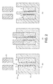
Figure 2 illustrates stages in the manufacture of the magnet ofFigure 1 ; -
Figure 3 is a sectional view of a further magnet in accordance with the present invention; and -
Figure 4 illustrates stages in the manufacture of the further magnet ofFigure 3 . - The
magnet 1 ofFigure 1 comprises acomposite body 2 having acoil 3 embedded therein. - The
composite body 2 is cylindrical in shape and comprises acentral bore 4 that extends through thebody 2 from afirst end 5 to asecond end 6. Thecomposite body 2 is formed of amagnetic powder 7 and abinder 8. - The
coil 3 is helical in shape and is formed of a ribbon that is thickest in a radial direction, i.e. in a direction normal to the longitudinal axis of thecoil 3. Thecoil 3 is embedded within thecomposite body 2 and is bound to thebody 2 by thebinder 8. Thecoil 3 extends along the full length of thecomposite body 2 from thefirst end 5 to thesecond end 6. Thecoil 3 surrounds and is coaxial with thebore 4. Moreover, the inner diameters of thecomposite body 2 and thecoil 3 are approximately the same such that thecoil 3 lies adjacent thebore 4. - The
magnet 1 may form part of a rotor of an electrical machine. In particular, a shaft may be secured within thebore 4, e.g. by means of an adhesive. As the rotor rotates, radial forces stress themagnet 1 radially and circumferentially. In the absence of thecoil 3, the resulting strain may cause thecomposite body 2 to fracture and break apart. Thecoil 3 has a greater radial stiffness and radial tensile strength than that of thecomposite body 2. Thecoil 3 therefore acts to oppose the radial and circumferential stresses acting on thecomposite body 2. As a result, excessive strain of thecomposite body 2, which might otherwise result in fracture of themagnet 1, may be avoided. Most binders are relatively good at opposing shearing stresses but are relatively poor at opposing purely tensile stresses. By embedding acoil 3 within thecomposite body 2, an interface is created between thecoil 3 and thebinder 8 that extends radially and circumferentially. Consequently, when themagnet 1 is subjected to radial forces, a shearing force is created between thebinder 8 and thecoil 3. Thebinder 8 is therefore able to effectively transfer the stresses from thecomposite body 2 to thecoil 3. In contrast, if thecoil 3 were replaced with a cylindrical sleeve, the interface between the sleeve and thebinder 8 would extend in an axial direction only. Consequently, when themagnet 1 is subjected to radial forces, a purely tensile stress is created between the sleeve and thebinder 8. As a result, the bond between thebinder 8 and the sleeve may fail. - By forming the
coil 3 from a ribbon, thebinder 8 binds to thecoil 3 over a larger surface area. Additionally, since the ribbon is thickest in the radial direction, a greater radial interface is created between thebinder 8 and thecoil 3. As a result, thebinder 8 is better able to transfer radial and circumferential stresses from thecomposite body 2 to thecoil 3. The radial stiffness of thecoil 3 is also increased. As a result, the axial thickness of thecoil 3 may reduced. This then permits a greater number of turns for thecoil 3, thus further strengthening thecomposite body 2. Furthermore, acoil 3 having a relatively weak axial stiffness may be used without compromising on radial stiffness. As detailed below, this then aids in the manufacture of themagnet 1 and reduces internal axial stresses. - The radial and circumferential stresses that arise during rotation of the
magnet 1 are greatest at thebore 4 of thecomposite body 2. By locating thecoil 3 adjacent thebore 4, thecoil 3 is better able to oppose stresses where they are greatest. - When the
magnet 1 rotates within a magnetic field, or is exposed to a rotating magnetic field (e.g. from a stator of an electrical machine), eddy currents will be induced in thecoil 3 if formed of an electrical conductor. The eddy currents will tend to circulate in loops parallel to the axis of rotation. Thecoil 3, being of a helical shape, does not include any continuous axial paths. As a result, any eddy currents induced in thecoil 3 will be relatively small. Additionally, by forming thecoil 3 from a ribbon, the axial thickness of thecoil 3 may be kept relatively small, thus further reducing the magnitude of any eddy currents. - Conventional rotors having a magnet secured to a shaft may include an outer sleeve that applies a compressive force to the magnet. However, the resulting stresses may cause the magnet to creep. As a result, the magnitude of the compressive force may decrease with time. Eventually, the compressive force may be insufficient to oppose the radial forces acting on the magnet and thus the magnet may fracture. In contrast, by embedding a
coil 3 within acomposite body 2, a reinforcedmagnet 1 is obtained without the need to pre-stress themagnet 1. Consequently, the ability of themagnet 1 to withstand radial forces does not diminish with time. Moreover, the sleeve may be omitted altogether and thus a cheaper and lighter rotor may be realised. - A method of manufacturing the
magnet 1 will now be described with reference toFigure 2 . - A
mould 10 having a cylindricalouter wall 11 and a centralcylindrical pin 12 upstanding from abase 13 is provided. Acoil 3 is placed onto thepin 12 of themould 10. A binder-coated magnetic powder 14 is then introduced into themould 10. The powder 14 penetrates the gaps in thecoil 3 and covers the top of thecoil 3. Apress 15 then applies a downward force and compresses thecoil 3 and the magnetic powder 14 within the mould so as to form aunitary magnet 1. Themagnet 1 is then removed from themould 10, placed in an oven, and heated so as to cure thebinder 8. - By employing a
coil 3 that compresses during compaction of the binder-coated powder 14, acomposite body 2 is obtained that has an embeddedcoil 3 that extends along the full length of thebody 2. Owing to manufacturing tolerances (e.g. tolerances in the amount of powder 14 introduced into themould 10, the distribution of the powder 14 within themould 10, and the magnitude of the downward force), there is a tolerance in length of thefinished magnet 1. Additionally, there is a tolerance in the initial length of thecoil 3. However, since thecoil 3 compresses along with the binder-coated powder 14, thefinished magnet 1 has an embeddedcoil 3 that extends along the full length of thecomposite body 2 irrespective of the manufacturing tolerances. - Forming the
coil 3 from a ribbon has two benefits in terms of the manufacture of themagnet 1. First, a ribbon presents a larger surface area over which thebinder 8 may bind to thecoil 3. Second, acoil 3 having a relatively weak axial stiffness may be used without compromising on radial stiffness. In having a relatively weak axial stiffness, thecoil 3 does not impact on the compressive force needed to form themagnet 1. Additionally, when themagnet 1 is removed frommould 10, the restoring force of thecoil 3 is relatively weak. There is therefore little danger of themagnet 1 breaking apart prior to or during curing. Additionally, internal axial stresses within themagnet 1 are relatively small. - The
coil 3 of the embodiment described above is resilient, which is to say that, when compressed, thecoil 3 generates a restoring force. However, thecoil 3 need not be resilient. When manufacturing themagnet 1, it is important only that thecoil 3 is capable of being compressed. It is not important that thecoil 3 is resilient. Indeed, it is advantageous to employ acoil 3 that is not resilient or has little resilience so as to minimise internal axial stresses within thefinished magnet 1. - When employing the method described above, the
coil 3 is first placed into themould 10 and then the magnetic powder 14 is introduced. As a result, relatively little magnetic power 14 surrounds the bottom turn of thecoil 3. There is therefore a risk that, when compressed, the restoring force of thecoil 3 may cause the bottom end of thecoil 3 to break through thelower end 6 of thecomposite body 2. In order to avoid this situation from arising, a small amount of magnet power 14 may be placed into themould 10 before inserting thecoil 3. Alternatively, thecoil 3 may terminate with straight axially-extending ends. Themagnet 1 is then manufactured in the same manner as that described above. The straight ends of thecoil 3 then ensure that magnetic power 14 finds it way both below and above the end turns of thecoil 3. - In the method described above, the
magnet 1 is removed after moulding and placed into an oven in order to cure thebinder 8. However, not all binders require elevated temperatures in order to cure. For example, thebinder 8 may cure under the compressive force applied by thepress 15, or thebinder 8 may cure at room temperature. It is not therefore essential to cure themagnet 1 at elevated temperatures after moulding. - Compression moulding has the advantage that the
magnet 1 may be manufactured using relatively small amounts of binder. As a result, amagnet 1 having relatively good magnetic properties may be achieved. Nevertheless, themagnet 1 may also be manufactured by injection moulding. For example, the composite ofmagnetic power 7 andbinder 8 may be heated to create a melt which is then injected into a mould containing thecoil 3. While injection moulding enables irregular-shaped magnets to be formed, a larger amount of binder is generally required in order that the melt has the necessary viscosity. This in turn results in a magnet having poorer magnetic properties. - The particular choice of
magnetic powder 7 andbinder 8 used for thecomposite body 2 is not deemed relevant to the present invention. Anymagnetic powder 7 andbinder 8 that are conventionally employed in the manufacture of bonded magnets may be used. - The
coil 3 is intended to oppose the radial and circumferential stresses that act on themagnet 1 during subsequent rotation. Accordingly, the material choice for thecoil 3, as well as the thickness and pitch of thecoil 3, will depend on the magnitude of the stresses. Suitable candidates for thecoil 3 include most metals, which have a relatively high stiffness and tensile strength, and will form a good bond with thebinder 8. Nevertheless, other materials, including plastics, may equally be used. - Curing the
magnet 1 at an elevated temperature may result in significant thermal expansion of themagnet 1. Alternatively, the temperature range over which themagnet 1 is required to operate may result in significant thermal expansion. The coefficients of thermal expansion for thecomposite body 2 and thecoil 3 are likely to be different. Consequently, thecomposite body 2 and thecoil 3 will expand and contract by different amounts. At elevated temperatures, thecomposite body 2 softens and thus any difference in the thermal expansions of thebody 2 and thecoil 3 may be accommodated through viscous deformation of thecomposite body 2. However, as themagnet 1 cools, thecomposite body 2 hardens. It is therefore unlikely that the difference in thermal contractions of thebody 2 and thecoil 3 can be accommodated wholly through viscous deformation of thecomposite body 2. If thecoil 3 has a coefficient of thermal expansion greater than that of thecomposite body 2, thecoil 3 will contract by a larger amount during cooling. As noted above, most binders are relatively good at opposing shear stress but relatively poor at opposing tensile stress. Consequently, as themagnet 1 cools, a low-density region is created in thecomposite body 2 at the outer edge of thecoil 3. - The size and density of the low-density region depend upon, among other things, the difference in the coefficients of thermal expansion of the
composite body 2 and thecoil 3. In particular, as the difference in the coefficients increases, the size of the low-density region increases and/or the density of the low-density region decreases. As the size of the low-density region increases and/or the pitch of thecoil 3 decreases, there comes a point at which the low-density region formed around one turn of thecoil 3 combines with the low-density regions formed around adjacent turns. The net result is a continuous low-density region located around thecoil 3. This continuous low-density region weakens the tensile strength of thecomposite body 2. Consequently, the tensile stresses that arise during rotation of themagnet 1 may cause thecomposite body 2 to split in two at the low-density region. - The applicant has found that, when the
magnet 1 is subjected to tensile stresses for which thecoil 3 was introduced, the likelihood of failure of thecomposite body 2 increases significantly when the coefficient of thermal expansion of thecoil 3 exceeds twice that of thecomposite body 2 and/or the pitch of thecoil 3 is less than 1 mm. That being said, failure of themagnet 1 due to the low-density region will depend upon many other factors. For example, the particular temperature at which themagnet 1 is cured, the rate at which themagnet 1 is subsequently cooled, and the viscosity of thecomposite body 2 are all likely to influence the size and density of the low-density regions. Nevertheless, it may be advantageous to employ acoil 3 for which the coefficient of thermal expansion is no greater than twice that of thecomposite body 2 and/or for which the pitch is no smaller than 1 mm. - Reference has thus far been made to a
magnet 1 having acoil 3 embedded within thecomposite body 2. However, themagnet 1 may be reinforced by embedding an alternative reinforcing element or elements in thecomposite body 2. By way of example,Figure 3 illustrates amagnet 1 in which a plurality ofwashers 16 are embedded within thecomposite body 2. Thewashers 16 surround thebore 4 and are spaced axially along the length of thebore 4. Thewashers 16, which are thickest in a radial direction, provide the very same advantages as that described above for thecoil 3. Indeed, thecoil 3 may be regarded as a plurality of linked washers. - By employing
washers 16, it is possible to have reinforcing elements for which the inner and outer diameters correspond to those of thecomposite body 2. Thebinder 8 then binds to each reinforcing element over a larger surface area. As a result, tensile stresses acting on thecomposite body 2 may be better transferred to the reinforcing elements. Additionally, since thebinder 8 is generally good at opposing shear stress, thermally-induced low-density regions within thecomposite body 2 may be avoided or significantly reduced in size. Furthermore, since thewashers 16 are radial thicker, it is possible to employ axially thinner reinforcing elements without compromising radial stiffness. Nevertheless, it is not essential that the inner and outer diameters of the washers correspond to those of thecomposite body 2. - A
magnet 1 having embeddedwashers 16 may be manufactured in a similar manner to that described above for thecoil 3. For example, a small amount of binder-coated magnetic powder 14 may be introduced into themould 10, after which awasher 16 is placed onto thepin 12 of themould 10. Further magnetic powder 14 is then introduced into themould 10 so as to cover thewasher 16, after which afurther washer 16 is placed onto thepin 12. This process is then repeated until themould 10 is filled to the required level. Thepress 15 then applies a downward force and compresses the magnetic powder 14 and thewashers 16 within themould 10 so as to form aunitary magnet 1. If necessary, themagnet 1 may be removed from themould 10, placed in an oven, and heated so as to cure thebinder 8. - An alternative method of manufacturing a
magnet 1 having embeddedwashers 16 will now be described with reference toFigure 4 . A plurality ofring magnets 17 are placed onto apin 18 of ajig 19. Eachring magnet 17 is formed of a composite ofmagnetic powder 7 andbinder 8, which may be cured or semi-cured. Awasher 16 is located between each pair ofring magnets 17. Thewasher 16 is formed of a pre-preg material, i.e. a composite of reinforcement fibres (e.g. carbon, aramid or glass fibres) impregnanted with a binder. Eachwasher 16 is relatively thin and may be formed by stamping a pre-preg tape or sheet. Apress 20 then applies a downward force on thering magnets 17 and thewashers 16 so as to form aunitary magnet 1. The downward force is relatively small and is intended only to ensure that thewashers 16, which are tacky, make good surface contact with thering magnets 17. Themagnet 1 is then removed from thejig 19, placed in an oven and cured at an elevated temperature. - There are several advantages in using a pre-preg material for the
washers 16. First, pre-preg materials typically have a relatively high stiffness and tensile strength. Second, in comparison to other materials having a high stiffness and tensile strength, particularly metals, the coefficient of thermal expansion of a pre-preg material is likely to more closely match that of thecomposite body 2. Third, the binder of a pre-preg material is generally tacky. Consequently, after locating thewashers 16 between thering magnets 17, the resulting assembly can be conveniently lifted from thejig 19 and placed in an oven for curing. Nevertheless, in spite of the aforementioned advantages, it is not essential that thewashers 16 are formed of a pre-preg material. For example, thewashers 16 may be formed of a metal. - Irrespective of whether the
washers 16 are formed of a pre-preg material, or whether thering magnets 17 are cured or semi-cured, it is important that at least one of thewashers 16 and thering magnets 17 comprises a curable binder. Themagnet 1 may then be manufactured by locating thewashers 16 between thering magnets 17 and curing the binder. Depending on the type of binder that is used, various options may be available for curing the binder, e.g. heat, pressure, UV light. - The term 'washer' should be understood to mean a flat annulus. However, it is not essential that the annulus is circular. For example, the annulus might be square or hexagonal. This would then make more efficient use of the pre-preg material when the
washer 16 is stamped from a pre-preg tape or sheet. Accordingly, in a more general sense, the term 'washer' should be understood to mean a flat element having a hole.
Claims (6)
- A rotor comprising a shaft secured to a magnet (1), the magnet comprising a composite body (2) having a bore (4) and a plurality of reinforcing elements (16) embedded within the body (2), wherein the composite body (2) comprises a magnetic powder (7) and a binder (8), the shaft is secured within the bore (4), and the reinforcing elements (16) are spaced axially within the body (2), and each reinforcing element (16) comprises a washer that surrounds the bore (4).
- A rotor as claimed in claim 1, wherein each reinforcing element (16) is thickest in a radial direction.
- A rotor as claimed in claim 1 or claim 2, wherein each reinforcing element (16) is adjacent the bore (4).
- A rotor as claimed in any one of the preceding claims, wherein each reinforcing element (16) has a coefficient of thermal expansion no greater than twice that of the composite body (2).
- A method of manufacturing a magnet (1), the method comprising:providing a mould (10) having a pin (12);placing a plurality of reinforcing elements (16) onto the pin (12), the plurality of reinforcing elements being washers;introducing a binder-coated magnetic powder (14) into the mould (10) such that the plurality of reinforcing elements (16) are spaced axially along the pin by the powder; andcompressing the powder (14) and the reinforcing element (3, 16).
- A method as claimed in claim 5, wherein each washer (16) is formed of a pre-preg material.
Applications Claiming Priority (2)
| Application Number | Priority Date | Filing Date | Title |
|---|---|---|---|
| GBGB1016006.7A GB201016006D0 (en) | 2010-09-23 | 2010-09-23 | A reinforced magnet |
| EP11760821.6A EP2619777B1 (en) | 2010-09-23 | 2011-09-02 | A reinforced magnet |
Related Parent Applications (2)
| Application Number | Title | Priority Date | Filing Date |
|---|---|---|---|
| EP11760821.6A Division EP2619777B1 (en) | 2010-09-23 | 2011-09-02 | A reinforced magnet |
| EP11760821.6A Division-Into EP2619777B1 (en) | 2010-09-23 | 2011-09-02 | A reinforced magnet |
Publications (1)
| Publication Number | Publication Date |
|---|---|
| EP2942797A1 true EP2942797A1 (en) | 2015-11-11 |
Family
ID=43127841
Family Applications (2)
| Application Number | Title | Priority Date | Filing Date |
|---|---|---|---|
| EP11760821.6A Not-in-force EP2619777B1 (en) | 2010-09-23 | 2011-09-02 | A reinforced magnet |
| EP15166140.2A Withdrawn EP2942797A1 (en) | 2010-09-23 | 2011-09-02 | A reinforced magnet |
Family Applications Before (1)
| Application Number | Title | Priority Date | Filing Date |
|---|---|---|---|
| EP11760821.6A Not-in-force EP2619777B1 (en) | 2010-09-23 | 2011-09-02 | A reinforced magnet |
Country Status (7)
| Country | Link |
|---|---|
| US (2) | US8736410B2 (en) |
| EP (2) | EP2619777B1 (en) |
| JP (2) | JP5578733B2 (en) |
| KR (1) | KR101430543B1 (en) |
| CN (2) | CN104953741B (en) |
| GB (2) | GB201016006D0 (en) |
| WO (1) | WO2012038716A1 (en) |
Cited By (1)
| Publication number | Priority date | Publication date | Assignee | Title |
|---|---|---|---|---|
| WO2018014141A1 (en) * | 2016-07-18 | 2018-01-25 | Bomatec Holding Ag | Segmented permanent magnets |
Families Citing this family (5)
| Publication number | Priority date | Publication date | Assignee | Title |
|---|---|---|---|---|
| ITMI20121606A1 (en) | 2012-09-26 | 2014-03-27 | Mavel Srl | METHOD OF MANUFACTURING A ROTOR FOR ELECTRIC MOTORS AND ROTORS MADE WITH THIS METHOD |
| JP2015186333A (en) * | 2014-03-24 | 2015-10-22 | 日東電工株式会社 | Permanent magnet and method for manufacturing permanent magnet |
| CN105608971A (en) * | 2016-03-25 | 2016-05-25 | 贵州励天科技发展有限公司 | Electromagnetic propulsion device |
| US10718105B2 (en) | 2017-03-02 | 2020-07-21 | Kohler Co. | Handwashing station |
| CN110752724A (en) * | 2019-12-02 | 2020-02-04 | 北京泓慧国际能源技术发展有限公司 | Permanent magnet motor rotor manufacturing method, motor rotor and permanent magnet motor |
Citations (7)
| Publication number | Priority date | Publication date | Assignee | Title |
|---|---|---|---|---|
| FR798073A (en) | 1934-11-29 | 1936-05-08 | Permanent magnet for stator or rotor of small electrical machines | |
| US3659129A (en) * | 1970-09-15 | 1972-04-25 | Gen Electric | Insulated bar dynamoelectric machine and method of forming |
| WO1994006193A1 (en) * | 1992-09-07 | 1994-03-17 | British Nuclear Fuels Plc | A fibre reinforced rotor |
| US5448123A (en) * | 1992-05-05 | 1995-09-05 | Atlas Copco Tools Ab | Electric synchronous motor |
| WO1997000549A1 (en) * | 1995-06-17 | 1997-01-03 | Urenco (Capenhurst) Limited | A rotor |
| WO2000059097A1 (en) * | 1999-03-26 | 2000-10-05 | Atlas Copco Controls Ab | Rotor for a high speed permanent magnet motor |
| EP1439627A1 (en) | 2003-01-17 | 2004-07-21 | Morganite Incorporated | Integrated slip-ring with sense magnet |
Family Cites Families (42)
| Publication number | Priority date | Publication date | Assignee | Title |
|---|---|---|---|---|
| US3482156A (en) * | 1966-07-19 | 1969-12-02 | Nachum Porath | Permanent magnet rotor type motor and control therefor |
| US3882442A (en) | 1973-01-12 | 1975-05-06 | Motor Wheel Corp | Transducer device for electrically operated brakes |
| GB1414949A (en) * | 1974-02-05 | 1975-11-19 | Laing Ingeborg | Rotary magnetic machines |
| US4065190A (en) | 1974-05-03 | 1977-12-27 | Skf Industrial Trading And Development Company, B.V. | Self adjusting elevating temperature bearing and housing |
| DE2608421C3 (en) * | 1976-03-01 | 1979-01-18 | Siemens Ag, 1000 Berlin Und 8000 Muenchen | Internal rotor with permanent magnet excitation for a synchronous machine |
| US4406958A (en) * | 1981-04-06 | 1983-09-27 | The Superior Electric Company | Stepping motors with disc magnet |
| SE455010B (en) * | 1982-03-31 | 1988-06-13 | Skf Ab | NAV FOR FLEETS AND PROCEDURE FOR PREPARING THE NAV |
| JPS60130811A (en) | 1983-12-19 | 1985-07-12 | Matsushita Electric Ind Co Ltd | Rotary transformer and manufacture thereof |
| JPS62144557A (en) * | 1985-12-18 | 1987-06-27 | Toshiba Corp | Rotor core for stepping motor |
| JPS6318950A (en) * | 1986-07-11 | 1988-01-26 | Matsushita Electric Ind Co Ltd | Permanent magnet rotor |
| JPS6338304U (en) * | 1986-08-29 | 1988-03-11 | ||
| CH674278A5 (en) * | 1987-10-16 | 1990-05-15 | Portescap | |
| JPH01129741A (en) * | 1987-11-13 | 1989-05-23 | Mitsubishi Metal Corp | Magnet for rotor |
| SE501855C2 (en) * | 1990-11-19 | 1995-06-06 | Skf Ab | Castings with molded reinforcement, and method of making such castings |
| JP3108931B2 (en) * | 1991-03-15 | 2000-11-13 | 株式会社トーキン | Inductor and manufacturing method thereof |
| SE500596C2 (en) * | 1992-05-05 | 1994-07-18 | Atlas Copco Tools Ab | Electric synchronous motor |
| JP3139148B2 (en) | 1992-07-24 | 2001-02-26 | 昭和電工株式会社 | Resin composition |
| JPH0641380U (en) * | 1992-09-11 | 1994-05-31 | セイコーエプソン株式会社 | Permanent magnet rotor |
| GB9313943D0 (en) * | 1993-07-06 | 1993-08-18 | British Nuclear Fuels Plc | Rotors |
| US6259180B1 (en) * | 1996-07-02 | 2001-07-10 | Schlenker Enterprises, Ltd. | Motor including embedded permanent magnet rotor and method for making the same |
| GB2297870A (en) * | 1995-02-09 | 1996-08-14 | British Nuclear Fuels Plc | An energy storage and conversion apparatus |
| JPH08237915A (en) * | 1995-12-14 | 1996-09-13 | Fuji Koki Seisakusho:Kk | Electric motor |
| KR0164995B1 (en) * | 1995-12-26 | 1999-01-15 | 정몽원 | The process of bond magnetics |
| JP3458667B2 (en) * | 1996-01-31 | 2003-10-20 | 富士ゼロックス株式会社 | motor |
| CN1173062A (en) * | 1996-08-01 | 1998-02-11 | 陈启星 | Magnetic telescopic dynamo-electric machine with reinforced structure |
| EP0854558A3 (en) * | 1997-01-21 | 2000-07-12 | Isuzu Ceramics Research Institute Co., Ltd. | Structure of a rotor for generators and method of manufacturing the same rotor |
| JPH10210691A (en) * | 1997-01-21 | 1998-08-07 | Isuzu Ceramics Kenkyusho:Kk | Structure of rotor in generator and method of manufacturing rotor |
| JP3856958B2 (en) * | 1998-07-16 | 2006-12-13 | 日本電産株式会社 | motor |
| WO2000065115A2 (en) * | 1999-04-28 | 2000-11-02 | Allison Engine Company, Inc. | Fiber reinforced composite material system |
| US6137390A (en) | 1999-05-03 | 2000-10-24 | Industrial Technology Research Institute | Inductors with minimized EMI effect and the method of manufacturing the same |
| JP3670575B2 (en) | 2000-01-12 | 2005-07-13 | Tdk株式会社 | Method for manufacturing coil-enclosed dust core and coil-enclosed dust core |
| JP2002319520A (en) * | 2001-04-20 | 2002-10-31 | Murata Mfg Co Ltd | Inductor and manufacturing method thereof |
| WO2004008607A1 (en) * | 2002-07-10 | 2004-01-22 | Hitachi, Ltd. | Magnet motor |
| JP4007591B2 (en) * | 2002-12-18 | 2007-11-14 | 株式会社豊田中央研究所 | Integrally molded composite member, manufacturing method thereof, and electromagnetic drive device |
| JP2004311771A (en) * | 2003-04-08 | 2004-11-04 | Ricoh Co Ltd | Long magnet, method of manufacturing the same, magnet roller, and image forming apparatus |
| JP2005312103A (en) | 2004-04-16 | 2005-11-04 | Sumitomo Electric Ind Ltd | Manufacturing method of dust core |
| US7679252B2 (en) * | 2005-04-13 | 2010-03-16 | Aisin Seiki Kabushiki Kaisha | Magnet embedded motor, rotor unit, and method for manufacturing rotor unit |
| GB0518787D0 (en) * | 2005-09-15 | 2005-10-26 | Khoo Wee K | Reinforced discs for magnetic bearings and electrical machines |
| EP2013408B2 (en) * | 2006-05-02 | 2016-09-28 | Rohr, Inc. | Nacelles and components thereof using nanoreinforcements |
| US20080044680A1 (en) * | 2006-08-18 | 2008-02-21 | Maglev Technologies, Llc | Magnetic composites |
| SE533657C2 (en) * | 2007-10-16 | 2010-11-23 | Magnetic Components Sweden Ab | Powder-based, soft magnetic, inductive component and method and apparatus for manufacturing thereof |
| IT1391357B1 (en) * | 2008-10-07 | 2011-12-13 | P R Nastri Trasportatori S N C Di Rubino Vincenzo & Rubino Attilio | COMPOSITE MATERIAL THAT CAN BE DETECTED BY METAL DETECTOR, ITEM IN SUCH COMPOSITE MATERIAL AND METHOD OF OBTAINING THESE ARTICLE |
-
2010
- 2010-09-23 GB GBGB1016006.7A patent/GB201016006D0/en not_active Ceased
-
2011
- 2011-09-02 KR KR1020137005358A patent/KR101430543B1/en not_active Expired - Fee Related
- 2011-09-02 WO PCT/GB2011/051651 patent/WO2012038716A1/en not_active Ceased
- 2011-09-02 CN CN201510441655.7A patent/CN104953741B/en active Active
- 2011-09-02 GB GB1115159.4A patent/GB2483967B/en not_active Expired - Fee Related
- 2011-09-02 CN CN201180045662.5A patent/CN103140901B/en active Active
- 2011-09-02 EP EP11760821.6A patent/EP2619777B1/en not_active Not-in-force
- 2011-09-02 EP EP15166140.2A patent/EP2942797A1/en not_active Withdrawn
- 2011-09-22 JP JP2011207423A patent/JP5578733B2/en not_active Expired - Fee Related
- 2011-09-22 US US13/240,676 patent/US8736410B2/en active Active
-
2013
- 2013-01-04 US US13/734,437 patent/US8741088B2/en not_active Expired - Fee Related
-
2014
- 2014-04-02 JP JP2014076233A patent/JP5895015B2/en not_active Expired - Fee Related
Patent Citations (7)
| Publication number | Priority date | Publication date | Assignee | Title |
|---|---|---|---|---|
| FR798073A (en) | 1934-11-29 | 1936-05-08 | Permanent magnet for stator or rotor of small electrical machines | |
| US3659129A (en) * | 1970-09-15 | 1972-04-25 | Gen Electric | Insulated bar dynamoelectric machine and method of forming |
| US5448123A (en) * | 1992-05-05 | 1995-09-05 | Atlas Copco Tools Ab | Electric synchronous motor |
| WO1994006193A1 (en) * | 1992-09-07 | 1994-03-17 | British Nuclear Fuels Plc | A fibre reinforced rotor |
| WO1997000549A1 (en) * | 1995-06-17 | 1997-01-03 | Urenco (Capenhurst) Limited | A rotor |
| WO2000059097A1 (en) * | 1999-03-26 | 2000-10-05 | Atlas Copco Controls Ab | Rotor for a high speed permanent magnet motor |
| EP1439627A1 (en) | 2003-01-17 | 2004-07-21 | Morganite Incorporated | Integrated slip-ring with sense magnet |
Cited By (1)
| Publication number | Priority date | Publication date | Assignee | Title |
|---|---|---|---|---|
| WO2018014141A1 (en) * | 2016-07-18 | 2018-01-25 | Bomatec Holding Ag | Segmented permanent magnets |
Also Published As
| Publication number | Publication date |
|---|---|
| KR20130039343A (en) | 2013-04-19 |
| JP5578733B2 (en) | 2014-08-27 |
| CN103140901B (en) | 2016-02-17 |
| KR101430543B1 (en) | 2014-08-14 |
| JP5895015B2 (en) | 2016-03-30 |
| CN104953741A (en) | 2015-09-30 |
| CN103140901A (en) | 2013-06-05 |
| US20130146206A1 (en) | 2013-06-13 |
| EP2619777A1 (en) | 2013-07-31 |
| US20120074806A1 (en) | 2012-03-29 |
| CN104953741B (en) | 2018-09-25 |
| GB201016006D0 (en) | 2010-11-10 |
| JP2014180202A (en) | 2014-09-25 |
| GB2483967B (en) | 2014-12-31 |
| JP2012069951A (en) | 2012-04-05 |
| EP2619777B1 (en) | 2015-11-04 |
| US8741088B2 (en) | 2014-06-03 |
| GB2483967A (en) | 2012-03-28 |
| WO2012038716A1 (en) | 2012-03-29 |
| GB201115159D0 (en) | 2011-10-19 |
| US8736410B2 (en) | 2014-05-27 |
Similar Documents
| Publication | Publication Date | Title |
|---|---|---|
| US8839505B2 (en) | Method of manufacturing a magnet assembly | |
| EP2619777B1 (en) | A reinforced magnet | |
| EP4327436A1 (en) | Rotor | |
| EP3579384B1 (en) | Bonded rotor shaft | |
| US9018817B2 (en) | Retaining bands | |
| CN103609001B (en) | Rotor cover for generator | |
| JPH0919093A (en) | Rotor permanent magnet | |
| EP2050179B1 (en) | A motor rotor and a method of manufacturing the same | |
| EP3219487A1 (en) | Composite flywheel | |
| WO2011106756A2 (en) | Improved magnet rotor assembly with increased physical strength | |
| CN114072989B (en) | Rotor and motor | |
| EP1385253B1 (en) | High speed rotor | |
| WO2009047094A1 (en) | Rotor for an electric machine and electric machine | |
| EP2712061B1 (en) | Method of manufacturing a rotor for electric motors | |
| JP2003079113A (en) | Resin-sealed electric motor stator, manufacturing method thereof and resin-sealing mold | |
| JPH04368440A (en) | Rotor | |
| CN109386550A (en) | Loading ability of bearing part or housing parts and its manufacturing method |
Legal Events
| Date | Code | Title | Description |
|---|---|---|---|
| PUAI | Public reference made under article 153(3) epc to a published international application that has entered the european phase |
Free format text: ORIGINAL CODE: 0009012 |
|
| AC | Divisional application: reference to earlier application |
Ref document number: 2619777 Country of ref document: EP Kind code of ref document: P |
|
| AK | Designated contracting states |
Kind code of ref document: A1 Designated state(s): AL AT BE BG CH CY CZ DE DK EE ES FI FR GB GR HR HU IE IS IT LI LT LU LV MC MK MT NL NO PL PT RO RS SE SI SK SM TR |
|
| 17P | Request for examination filed |
Effective date: 20160506 |
|
| RBV | Designated contracting states (corrected) |
Designated state(s): AL AT BE BG CH CY CZ DE DK EE ES FI FR GB GR HR HU IE IS IT LI LT LU LV MC MK MT NL NO PL PT RO RS SE SI SK SM TR |
|
| GRAP | Despatch of communication of intention to grant a patent |
Free format text: ORIGINAL CODE: EPIDOSNIGR1 |
|
| INTG | Intention to grant announced |
Effective date: 20181025 |
|
| STAA | Information on the status of an ep patent application or granted ep patent |
Free format text: STATUS: THE APPLICATION IS DEEMED TO BE WITHDRAWN |
|
| 18D | Application deemed to be withdrawn |
Effective date: 20190305 |