EP2942222A1 - Heat exchanger assembly for a drive unit of an agricultural machine - Google Patents
Heat exchanger assembly for a drive unit of an agricultural machine Download PDFInfo
- Publication number
- EP2942222A1 EP2942222A1 EP15157993.5A EP15157993A EP2942222A1 EP 2942222 A1 EP2942222 A1 EP 2942222A1 EP 15157993 A EP15157993 A EP 15157993A EP 2942222 A1 EP2942222 A1 EP 2942222A1
- Authority
- EP
- European Patent Office
- Prior art keywords
- heat exchanger
- cooling air
- cooling
- air guide
- arrangement according
- Prior art date
- Legal status (The legal status is an assumption and is not a legal conclusion. Google has not performed a legal analysis and makes no representation as to the accuracy of the status listed.)
- Ceased
Links
Images
Classifications
-
- B—PERFORMING OPERATIONS; TRANSPORTING
- B60—VEHICLES IN GENERAL
- B60K—ARRANGEMENT OR MOUNTING OF PROPULSION UNITS OR OF TRANSMISSIONS IN VEHICLES; ARRANGEMENT OR MOUNTING OF PLURAL DIVERSE PRIME-MOVERS IN VEHICLES; AUXILIARY DRIVES FOR VEHICLES; INSTRUMENTATION OR DASHBOARDS FOR VEHICLES; ARRANGEMENTS IN CONNECTION WITH COOLING, AIR INTAKE, GAS EXHAUST OR FUEL SUPPLY OF PROPULSION UNITS IN VEHICLES
- B60K11/00—Arrangement in connection with cooling of propulsion units
- B60K11/08—Air inlets for cooling; Shutters or blinds therefor
- B60K11/085—Air inlets for cooling; Shutters or blinds therefor with adjustable shutters or blinds
-
- F—MECHANICAL ENGINEERING; LIGHTING; HEATING; WEAPONS; BLASTING
- F01—MACHINES OR ENGINES IN GENERAL; ENGINE PLANTS IN GENERAL; STEAM ENGINES
- F01P—COOLING OF MACHINES OR ENGINES IN GENERAL; COOLING OF INTERNAL-COMBUSTION ENGINES
- F01P7/00—Controlling of coolant flow
- F01P7/02—Controlling of coolant flow the coolant being cooling-air
- F01P7/10—Controlling of coolant flow the coolant being cooling-air by throttling amount of air flowing through liquid-to-air heat exchangers
- F01P7/12—Controlling of coolant flow the coolant being cooling-air by throttling amount of air flowing through liquid-to-air heat exchangers by thermostatic control
-
- F—MECHANICAL ENGINEERING; LIGHTING; HEATING; WEAPONS; BLASTING
- F02—COMBUSTION ENGINES; HOT-GAS OR COMBUSTION-PRODUCT ENGINE PLANTS
- F02B—INTERNAL-COMBUSTION PISTON ENGINES; COMBUSTION ENGINES IN GENERAL
- F02B29/00—Engines characterised by provision for charging or scavenging not provided for in groups F02B25/00, F02B27/00 or F02B33/00 - F02B39/00; Details thereof
- F02B29/04—Cooling of air intake supply
- F02B29/0406—Layout of the intake air cooling or coolant circuit
- F02B29/0425—Air cooled heat exchangers
- F02B29/0431—Details or means to guide the ambient air to the heat exchanger, e.g. having a fan, flaps, a bypass or a special location in the engine compartment
-
- F—MECHANICAL ENGINEERING; LIGHTING; HEATING; WEAPONS; BLASTING
- F02—COMBUSTION ENGINES; HOT-GAS OR COMBUSTION-PRODUCT ENGINE PLANTS
- F02B—INTERNAL-COMBUSTION PISTON ENGINES; COMBUSTION ENGINES IN GENERAL
- F02B29/00—Engines characterised by provision for charging or scavenging not provided for in groups F02B25/00, F02B27/00 or F02B33/00 - F02B39/00; Details thereof
- F02B29/04—Cooling of air intake supply
- F02B29/045—Constructional details of the heat exchangers, e.g. pipes, plates, ribs, insulation, materials, or manufacturing and assembly
- F02B29/0456—Air cooled heat exchangers
-
- F—MECHANICAL ENGINEERING; LIGHTING; HEATING; WEAPONS; BLASTING
- F02—COMBUSTION ENGINES; HOT-GAS OR COMBUSTION-PRODUCT ENGINE PLANTS
- F02B—INTERNAL-COMBUSTION PISTON ENGINES; COMBUSTION ENGINES IN GENERAL
- F02B29/00—Engines characterised by provision for charging or scavenging not provided for in groups F02B25/00, F02B27/00 or F02B33/00 - F02B39/00; Details thereof
- F02B29/04—Cooling of air intake supply
- F02B29/0493—Controlling the air charge temperature
-
- B—PERFORMING OPERATIONS; TRANSPORTING
- B60—VEHICLES IN GENERAL
- B60Y—INDEXING SCHEME RELATING TO ASPECTS CROSS-CUTTING VEHICLE TECHNOLOGY
- B60Y2200/00—Type of vehicle
- B60Y2200/20—Off-Road Vehicles
- B60Y2200/22—Agricultural vehicles
- B60Y2200/221—Tractors
-
- F—MECHANICAL ENGINEERING; LIGHTING; HEATING; WEAPONS; BLASTING
- F01—MACHINES OR ENGINES IN GENERAL; ENGINE PLANTS IN GENERAL; STEAM ENGINES
- F01P—COOLING OF MACHINES OR ENGINES IN GENERAL; COOLING OF INTERNAL-COMBUSTION ENGINES
- F01P3/00—Liquid cooling
- F01P3/18—Arrangements or mounting of liquid-to-air heat-exchangers
- F01P2003/187—Arrangements or mounting of liquid-to-air heat-exchangers arranged in series
-
- Y—GENERAL TAGGING OF NEW TECHNOLOGICAL DEVELOPMENTS; GENERAL TAGGING OF CROSS-SECTIONAL TECHNOLOGIES SPANNING OVER SEVERAL SECTIONS OF THE IPC; TECHNICAL SUBJECTS COVERED BY FORMER USPC CROSS-REFERENCE ART COLLECTIONS [XRACs] AND DIGESTS
- Y02—TECHNOLOGIES OR APPLICATIONS FOR MITIGATION OR ADAPTATION AGAINST CLIMATE CHANGE
- Y02T—CLIMATE CHANGE MITIGATION TECHNOLOGIES RELATED TO TRANSPORTATION
- Y02T10/00—Road transport of goods or passengers
- Y02T10/10—Internal combustion engine [ICE] based vehicles
- Y02T10/12—Improving ICE efficiencies
-
- Y—GENERAL TAGGING OF NEW TECHNOLOGICAL DEVELOPMENTS; GENERAL TAGGING OF CROSS-SECTIONAL TECHNOLOGIES SPANNING OVER SEVERAL SECTIONS OF THE IPC; TECHNICAL SUBJECTS COVERED BY FORMER USPC CROSS-REFERENCE ART COLLECTIONS [XRACs] AND DIGESTS
- Y02—TECHNOLOGIES OR APPLICATIONS FOR MITIGATION OR ADAPTATION AGAINST CLIMATE CHANGE
- Y02T—CLIMATE CHANGE MITIGATION TECHNOLOGIES RELATED TO TRANSPORTATION
- Y02T10/00—Road transport of goods or passengers
- Y02T10/80—Technologies aiming to reduce greenhouse gasses emissions common to all road transportation technologies
- Y02T10/88—Optimized components or subsystems, e.g. lighting, actively controlled glasses
Definitions
- the invention relates to a heat exchanger arrangement for a drive unit of an agricultural working machine, in particular a tractor or a self-propelled harvester, with at least two directly juxtaposed, can be acted upon in parallel with a cooling air flow heat exchangers and at least one cooling air blower for generating a cooling air flow.
- corresponding drive units which are provided with a heat exchanger assembly
- a heat exchanger assembly it is in particular an internal combustion engine, wherein the heat exchangers are provided for example for cooling the cooling water or the charge air.
- components of corresponding drive units may be a mechanical or hydromechanical transmission and / or a hydrostatic drive system and / or a working hydraulics. In these cases, for example, a cooling of the transmission or hydraulic oil.
- part of the heat exchanger assembly may be a heat exchanger of an air conditioner.
- Agricultural work machines such as tractors, self-propelled harvesters, in particular combines, forage harvesters and the like, are usually equipped with a complex refrigeration system, since on board an agricultural work machine usually different operating and auxiliary equipment (e.g., engine coolant, charge air, transmission oil, hydraulic oil) are to be cooled.
- operating and auxiliary equipment e.g., engine coolant, charge air, transmission oil, hydraulic oil
- the cooling units of agricultural machines are combined coolers, ie several media are cooled at the same time. Accordingly, the cooling air flow of a single cooling air blower, a plurality of heat exchangers are applied, which are arranged for this purpose, for example, next to or behind each other.
- WO 2008/080305 A1 Reference should be made in this context by way of example WO 2008/080305 A1 ,
- the present invention has for its object to provide a heat exchanger assembly of the type mentioned, which has a reduced power requirement when required cooling of the heat exchanger.
- a heat exchanger assembly according to the features of claim 1. This is characterized in that relative to the direction of the cooling air flow in front of or behind each of the heat exchanger in each case an adjustable, the cooling air flow influencing air guide is arranged.
- heat exchangers are to be provided for different units and their parts. This may be in addition to the usual cooling water cooler and a charge air cooler of the internal combustion engine to cooler for a working hydraulics, for a hydrostatic or hydrodynamic drive and for a transmission and optionally a heat exchanger for an air conditioner.
- the corresponding heat exchangers or coolers are advantageously combined to form a block, that is to say preferably arranged in a frame.
- the air mass flow can be variably, in particular on demand and individually, split on the heat exchanger.
- the air guide elements of the heat exchanger with the highest cooling demand can be set, for example, to an opening cross section, which allows for this a high air mass flow, while heat exchangers with relatively low cooling demand, the associated air guide is set to a small opening cross-section.
- the flow rate on the warmest heat exchanger - at the same speed of the cooling air blower - continues to increase. This possibility of adjustment, the heat exchanger assembly has an increased energy efficiency.
- a flow cross section of the air guide elements should be infinitely adjustable.
- the corresponding cooling air requirement can be determined at each of the heat exchanger, which serves as a parameter for the air allocation and causes a change in the flow cross-section.
- the adjustment takes place continuously.
- an adjustment of the air guide elements can take place in several stages.
- the air guide elements of the individual heat exchangers are adjustable separately from each other. As a result, the air mass flow of a plurality of heat exchangers can be reduced and, in addition, fed to a heat exchanger, so that the flow velocity increases there and thus the heat can be dissipated to the required extent.
- the air guide elements are preferably designed as lamellae, which can each perform a pivoting movement between a maximum opening degree and a closed position.
- the individual air guide elements are adjustable depending on the cooling air requirement of each associated heat exchanger according to an advantageous development.
- the air guide elements each have an adjustment provided preferably electrical adjustment devices.
- the cooling air requirement of the respective heat exchanger is determined by a temperature sensor and a corresponding actual value transmitted to a Regeleitechnisch which controls the adjustment of the respective heat exchanger due to this actual value to set the air mass flow separately to the air mass flow of the other heat exchangers, which are also provided with adjusting ,
- the heat exchangers should be assigned a common cooling air blower. This can be arranged behind or in front of the heat exchangers in accordance with the previously stated arrangement of the air guide elements, viewed in the direction of the cooling air flow. Alternatively, it is possible to provide a plurality of cooling air blower, each associated with one or more heat exchangers. In both cases, the cooling air blowers are controlled as needed, that is, they are switched on or off and / or regulated in terms of their speed.
- an adjustment of the air guide elements and an adjustment of at least one drive of the at least one cooling air blower are connected to a control device, the speed of the at least one cooling air blower depending on the total cooling air requirement and the respective position of the air guide elements in dependence Cooling air requirement of this assigned heat exchanger adjusts.
- the air guide elements will be set to their largest flow cross section. If there is a lesser need for cooling air at individual heat exchangers, then the flow cross-section is throttled to this by means of the air guide elements. At the same time, the fan speed can be lowered. As a result, the total transferred to the at least one fan drive drive power can be reduced. Consequently, the heat exchanger assembly is operated with greater energy efficiency.
- control device is operable to increase a flow cross-section of that air guide element to a maximum value, whose associated heat exchanger has the highest cooling air requirement.
- control device is operable to reduce a flow cross-section of an air guide element to a lower maximum value (i.e., below the maximum lying value) if the heat exchanger associated with this air guide element has a smaller cooling air requirement than can be caused by the cooling air flow.
- the individual combined into a block heat exchanger for cooling the cooling water of an internal combustion engine and / or for cooling of a charge of an exhaust gas turbocharger charge air of the internal combustion engine and / or for cooling the engine oil of the internal combustion engine and / or for cooling a transmission oil and / or for cooling a Hydraulic oil be provided.
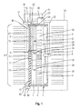
- 1 denotes a heat exchanger arrangement which has three heat exchangers 2, 3 and 4, which are arranged next to one another and thus are acted upon in parallel by a cooling air flow 5.
- the heat exchangers 2, 3 and 4 are enclosed by a frame-like frame 6, which can be fastened in a frame or block, not shown in detail in the figure also not shown agricultural or construction work machine.
- the heat exchanger assembly 1 and thus all heat exchangers 2, 3 and 4 is associated with acting as a suction fan cooling air fan 7, which - is arranged behind the heat exchanger assembly 1 in the flow direction of the aforementioned cooling air flow 5 and thus promotes this through the heat exchangers 2, 3 and 4.
- the cooling air blower 7 is driven by an electric fan motor 8 and has fan blades 9.
- a hydraulic fan motor 8 can also be used.
- a belt drive can be provided by means of which the cooling air fan 7 is driven by a controllable in its output speed clutch.
- part of the heat exchanger assembly 1 air guide elements 10, 11, and 12.
- the air guide element 10 is arranged in front of the heat exchanger 2, the air guide 11 in front of the heat exchanger 3 and the air guide 12 in front of the heat exchanger 4.
- the air guide elements 10, 11 and 12 each have between an open position and a closed position pivotable fins 13, which may be formed substantially identical.
- a flow cross section of the air guide elements 10, 11, 12 can be adjusted continuously depending on their position.
- This adjustment of the spoiler elements 10, 11 and 12 is carried out separately from each other, including the spoiler 10 an adjusting device 14 with an adjusting motor 15, the air guide 11 an adjusting 16 with an adjusting motor 17 and the air guide 13 an adjusting device 18 are associated with an adjusting 19.
- adjusting motors 15, 17 and 19, which perform a linear adjusting movement go out rods 20, 21 and 22, which engage the respective fins 13 of the air guide elements 10, 11 and 12 and these, as indicated, pivot.
- these could be designed as a fixed grid and a slide grate displaceable thereto.
- the heat exchanger assembly 1 a control device 23 which is connected via signal lines 24, 25 and 26 with temperature sensors 27, 28 and 29. These temperature sensors 27, 28 and 29 are each provided for detecting the temperatures of the heat exchangers 2, 3 and 4.
- the control device 23 encoder lines 30, 31, 32 and 33 go from the control device 23 encoder lines 30, 31, 32 and 33, to the Adjustment motors 15, 17 and 19 and are connected to the fan motor 8. Consequently, the control device 23, depending on the temperatures of the heat exchangers 2, 3 and 4 whose air guide elements 10, 11 and 12 are adjusted individually.
- the fan speed of the cooling air blower 7 is specified by the control device 23.
- the control device 23 is a speed of the cooling air blower 7 depending on the total cooling air requirement and the control device 23 sets a respective position of the air guide elements 10, 11, 12 in dependence on the cooling air requirement of the associated heat exchanger 2, 3, 4 a.
- the control device 23 is advantageously operable to increase a flow cross section of that air guide element 10, 11, 12 to a maximum value, whose associated heat exchanger 2, 3, 4 has the highest cooling air requirement.
- the control device is operable to reduce a flow cross-section of an air guide element 10, 11, 12 to a lower maximum value, if the this air guide element 10, 11, 12 associated heat exchanger 2, 3, 4 has a less than by the cooling air flow 5 effected cooling air requirement.
- the air guide 10 of the heat exchanger 2 is almost closed, the air guide 11 of the heat exchanger 3 is completely open and the air guide 12 of the heat exchanger 4 about half open.
- the groups of arrows 34, 35 and 36 shown on the outlet side of the heat exchanger arrangement 1 make it clear which flow rate and thus which air mass flow the individual heat exchangers 2, 3 and 4 are subjected to. Superior to the individual air mass flows of the entire air mass flow through the previously described adjustment of the fan motor 8 egg ngestel It.
- the heat exchanger arrangement according to the invention has the advantage that the power absorbed by the cooling air fan 7 can be reduced overall.
- the demand-dependent adjustment of the air guiding elements 10, 11 and 12 can also be used, in order to achieve a required operating temperature in individual heat exchangers 2, 3 and 4 for the corresponding medium.
Abstract
Eine Wärmetauscheranordnung (1) für eine Antriebseinheit einer landwirtschaftlichen Arbeitsmaschine, insbesondere eines Traktors oder einer selbstfahrenden Erntemaschine, mit zumindest zwei unmittelbar nebeneinander angeordneten, parallel mit einem Kühlluftstrom (5) beaufschlagbaren Wärmetauschern (2, 3, 4) und mit zumindest einem Kühlluftgebläse (7) zur Erzeugung eines Kühlluftstroms (5), zeichnet sich dadurch aus, dass bezogen auf die Richtung des Kühlluftstromes (5) vor oder hinter jedem der Wärmetauscher (2, 3, 4) jeweils ein verstellbares, den Kühlluftstrom (5) beeinflussendes Luftleitelement (10, 11, 12) angeordnet ist.A heat exchanger arrangement (1) for a drive unit of an agricultural working machine, in particular a tractor or a self-propelled harvesting machine, having at least two heat exchangers (2, 3, 4) which can be acted upon in parallel with a cooling air flow (5) and at least one cooling air blower (7 ) for generating a cooling air flow (5), characterized in that relative to the direction of the cooling air flow (5) before or after each of the heat exchangers (2, 3, 4) in each case an adjustable, the cooling air flow (5) influencing air guide element (10 , 11, 12) is arranged.
Description
Die Erfindung betrifft eine Wärmetauscheranordnung für eine Antriebseinheit einer landwirtschaftlichen Arbeitsmaschine, insbesondere eines Traktors oder einer selbstfahrenden Erntemaschine, mit zumindest zwei unmittelbar nebeneinander angeordneten, parallel mit einem Kühlluftstrom beaufschlagbaren Wärmetauschern und mit zumindest einem Kühlluftgebläse zur Erzeugung eines Kühlluftstroms.The invention relates to a heat exchanger arrangement for a drive unit of an agricultural working machine, in particular a tractor or a self-propelled harvester, with at least two directly juxtaposed, can be acted upon in parallel with a cooling air flow heat exchangers and at least one cooling air blower for generating a cooling air flow.
Bei entsprechenden Antriebseinheiten, die mit einer Wärmetauscheranordnung versehen sind, handelt es sich insbesondere um eine Brennkraftmaschine, wobei die Wärmetauscher beispielsweise zur Kühlung des Kühlwassers oder der Ladeluft vorgesehen sind. Weiterhin können Bestandteile entsprechender Antriebseinheiten ein mechanisches oder hydromechanisches Getriebe und/oder ein hydrostatisches Antriebssystem und/oder eine Arbeitshydraulik sein. In diesen Fällen erfolgt beispielsweise eine Kühlung des Getriebe- oder Hydrauliköls. Außerdem kann Bestandteil der Wärmetauscheranordnung ein Wärmetauscher einer Klimaanlage sein.In corresponding drive units, which are provided with a heat exchanger assembly, it is in particular an internal combustion engine, wherein the heat exchangers are provided for example for cooling the cooling water or the charge air. Furthermore, components of corresponding drive units may be a mechanical or hydromechanical transmission and / or a hydrostatic drive system and / or a working hydraulics. In these cases, for example, a cooling of the transmission or hydraulic oil. In addition, part of the heat exchanger assembly may be a heat exchanger of an air conditioner.
Landwirtschaftliche Arbeitsmaschinen wie Traktoren, selbstfahrende Erntemaschine insbesondere Mähdrescher, Feldhäcksler und dergleichen sind in der Regel mit einem komplexen Kühlsystem ausgestattet, da an Bord einer landwirtschaftlichen Arbeitsmaschine üblicherweise zugleich verschiedene Betriebs- und Hilfsmittel (z.B. Motorkühlflüssigkeit, Ladeluft, Getriebeöl, Hydrauliköl) zu kühlen sind.Agricultural work machines such as tractors, self-propelled harvesters, in particular combines, forage harvesters and the like, are usually equipped with a complex refrigeration system, since on board an agricultural work machine usually different operating and auxiliary equipment (e.g., engine coolant, charge air, transmission oil, hydraulic oil) are to be cooled.
Daneben besteht bei diesen Arbeitsmaschinen überhaupt ein hoher Leistungsbedarf, so dass immer größere Kühlleistungen erforderlich werden. Dem Erfordernis nach großer Kühlleistung steht die hohe Wärmeabgabe leistungsstarker Motoren entgegen, welche es schwierig macht, auf dem begrenzten Bauraum eine ausreichende Zufuhr kühler Außenluft zum Wärmetauscher zu gewährleisten.In addition, there is a high power consumption at all in these machines, so that ever greater cooling capacities are required. The requirement for high cooling capacity is counteracted by the high heat output of powerful motors, which makes it difficult to ensure sufficient supply of cool outside air to the heat exchanger in the limited installation space.
Eine naheliegende Lösung besteht darin, ein Kühlluftgebläse, das die verschiedenen Wärmetauscher mit einem Kühlluftstrom beaufschlagt, mit höherer Leistung zu betreiben, um die erforderliche Kühlung zu bewirken.An obvious solution is to operate a cooling air blower, which applies a cooling air flow to the various heat exchangers, with higher power in order to effect the required cooling.
Wie zuvor erwähnt, handelt es sich bei den Kühlaggregaten landwirtschaftlicher Arbeitsmaschinen um kombinierte Kühler, d.h. es werden zugleich mehrere Medien gekühlt. Demnach wird vom Kühlluftstrom eines einzigen Kühlluftgebläses eine Mehrzahl von Wärmetauschern beaufschlagt, die zu diesem Zweck beispielsweise neben-oder hintereinander angeordnet sind. Verwiesen sei in diesem Zusammenhang beispielhaft auf
Um Überhitzungen einzelner Komponenten sicher zu vermeiden, ist es erforderlich und üblich, das Kühlluftgebläse stets so einzustellen, dass der Wärmetauscher mit der höchsten Temperatur - bzw. der Lüfter mit dem größten Kühlbedarf - die Lüfterdrehzahl steuert. Dies hat jedoch zur Folge, dass die übrigen Wärmetauscher möglicherweise in einem stärkeren Maße als für diese - in einer bestimmten Betriebssituation - jeweils erforderlich gekühlt werden. Es wird somit eine unnötig hohe Antriebsleistung für das Kühlluftgebläse aufgebracht.In order to safely avoid overheating of individual components, it is necessary and customary to always set the cooling air fan so that the heat exchanger with the highest temperature - or the fan with the greatest cooling demand - controls the fan speed. However, this has the consequence that the other heat exchangers may possibly be cooled to a greater extent than for these - in a particular operating situation - each required. It is thus applied an unnecessarily high drive power for the cooling air blower.
Vor diesem Hintergrund liegt der vorliegenden Erfindung die Aufgabe zugrunde, eine Wärmetauscheranordnung der genannten Art anzugeben, die bei bedarfsgerechter Kühlung der Wärmetauscher einen verringerten Leistungsbedarf aufweist.Against this background, the present invention has for its object to provide a heat exchanger assembly of the type mentioned, which has a reduced power requirement when required cooling of the heat exchanger.
Die Aufgabe wird gelöst durch eine Wärmetauscheranordnung gemäß den Merkmalen des Anspruchs 1. Diese zeichnet sich dadurch aus, dass bezogen auf die Richtung des Kühlluftstromes vor oder hinter jedem der Wärmetauscher jeweils ein verstellbares, den Kühlluftstrom beeinflussendes Luftleitelement angeordnet ist.The object is achieved by a heat exchanger assembly according to the features of
An einer landwirtschaftlichen Arbeitsmaschine, die zum Teil unter extremen Betriebsbedingung und mit hoher Leistung betrieben wird, sind für unterschiedliche Aggregate und deren Teile Wärmetauscher vorzusehen. Dabei kann es sich neben dem üblichen Kühlwasserkühler und einem Ladeluftkühler der Brennkraftmaschine um Kühler für eine Arbeitshydraulik, für einen hydrostatischen oder hydrodynamischen Antrieb sowie für ein Getriebe und gegebenenfalls einen Wärmetauscher für eine Klimaanlage handeln.On an agricultural working machine, which is partly operated under extreme operating conditions and with high power, heat exchangers are to be provided for different units and their parts. This may be in addition to the usual cooling water cooler and a charge air cooler of the internal combustion engine to cooler for a working hydraulics, for a hydrostatic or hydrodynamic drive and for a transmission and optionally a heat exchanger for an air conditioner.
Die entsprechenden Wärmetauscher oder Kühler sind in vorteilhafter Weise zu einem Block zusammengefasst, also vorzugsweise in einem Rahmen angeordnet. Durch die Steuerung des Luftmassenstroms an jedem der Wärmetauscher mittels der diesen vor-oder nachgeordneten Luftleitelemente lässt sich der Luftmassenstrom variabel, insbesondere bedarfsgerecht und individuell, auf die Wärmetauscher aufteilen. Die Luftleitelemente des Wärmetauschers mit dem höchsten Kühlbedarf können so beispielsweise auf einen Öffnungsquerschnitt eingestellt werden, der für diesen einen hohen Luftmassenstrom ermöglicht, während an Wärmetauschern mit verhältnismäßig geringem Kühlbedarf das zugehörige Luftleitelement auf einen geringen Öffnungsquerschnitt eingestellt wird. So steigt die Strömungsgeschwindigkeit am wärmsten Wärmetauscher - bei gleicher Drehzahl des Kühlluftgebläses - weiter an. Durch diese Möglichkeit der Verstellung weist die Wärmetauscheranordnung eine erhöhte Energieeffizienz auf.The corresponding heat exchangers or coolers are advantageously combined to form a block, that is to say preferably arranged in a frame. By controlling the air mass flow at each of the heat exchangers by means of these upstream or downstream air guide elements, the air mass flow can be variably, in particular on demand and individually, split on the heat exchanger. The air guide elements of the heat exchanger with the highest cooling demand can be set, for example, to an opening cross section, which allows for this a high air mass flow, while heat exchangers with relatively low cooling demand, the associated air guide is set to a small opening cross-section. Thus, the flow rate on the warmest heat exchanger - at the same speed of the cooling air blower - continues to increase. This possibility of adjustment, the heat exchanger assembly has an increased energy efficiency.
In weiterer Ausgestaltung der erfindungsgemäßen Lösung soll ein Strömungsquerschnitt der Luftleitelemente stufenlos verstellbar sein. Damit kann an jedem der Wärmetauscher der entsprechende Kühlluftbedarf ermittelt werden, der als Parameter für die Luftzuteilung dient und eine Veränderung des Strömungsquerschnitts bewirkt. In vorteilhafter Weise erfolgt dabei die Verstellung stufenlos. Alternativ dazu kann aber auch eine Verstellung der Luftleitelemente in mehreren Stufen erfolgen.In a further embodiment of the solution according to the invention, a flow cross section of the air guide elements should be infinitely adjustable. Thus, the corresponding cooling air requirement can be determined at each of the heat exchanger, which serves as a parameter for the air allocation and causes a change in the flow cross-section. Advantageously, the adjustment takes place continuously. Alternatively, however, an adjustment of the air guide elements can take place in several stages.
Weiterhin ist vorgesehen, dass die Luftleitelemente der einzelnen Wärmetauscher getrennt voneinander verstellbar sind. Dadurch kann der Luftmassenstrom mehrerer Wärmetauscher reduziert und zusätzlich einem Wärmetauscher zugeführt werden, so dass an diesem die Strömungsgeschwindigkeit steigt und somit die Wärme in erforderlichem Maße abgeführt werden kann. Die Luftleitelemente sind vorzugsweise als Lamellen ausgebildet, wobei diese jeweils eine Schwenkbewegung zwischen einem maximalen Öffnungsgrad und einer Schließstellung ausführen können. Darüber hinaus besteht die Möglichkeit, die Luftleitelemente als Schieber auszubilden, wozu ein festes Gitter und ein dazu verschiebbares Schiebegitter vorgesehen sind.Furthermore, it is provided that the air guide elements of the individual heat exchangers are adjustable separately from each other. As a result, the air mass flow of a plurality of heat exchangers can be reduced and, in addition, fed to a heat exchanger, so that the flow velocity increases there and thus the heat can be dissipated to the required extent. The air guide elements are preferably designed as lamellae, which can each perform a pivoting movement between a maximum opening degree and a closed position. In addition, it is possible to form the spoiler elements as a slide, including a fixed grid and a sliding grate sliding thereto are provided.
Grundsätzlich unabhängig von der jeweils gewählten Bauform der Luftleitelemente sind gemäß einer vorteilhaften Weiterbildung die einzelnen Luftleitelemente abhängig vom Kühlluftbedarf des jeweils zugehörigen Wärmetauschers einstellbar.Basically, regardless of the selected design of the air guide elements, the individual air guide elements are adjustable depending on the cooling air requirement of each associated heat exchanger according to an advantageous development.
Außerdem ist vorteilhaft vorgesehen, dass die Luftleitelemente jeweils mit einem Verstellmotor versehene bevorzugt elektrische Verstelleinrichtungen aufweisen. Dabei wird der Kühlluftbedarf des jeweiligen Wärmetauschers über einen Temperatursensor ermittelt und ein entsprechender Istwert an eine Regeleirichtung übertragen, die aufgrund dieses Istwertes den Verstellmotor des betreffenden Wärmetauschers ansteuert, um dessen Luftmassenstrom getrennt zu den Luftmassenströmen der übrigen Wärmetauscher, die ebenfalls mit Verstellmotoren versehen sind, einzustellen.In addition, it is advantageously provided that the air guide elements each have an adjustment provided preferably electrical adjustment devices. In this case, the cooling air requirement of the respective heat exchanger is determined by a temperature sensor and a corresponding actual value transmitted to a Regeleirichtung which controls the adjustment of the respective heat exchanger due to this actual value to set the air mass flow separately to the air mass flow of the other heat exchangers, which are also provided with adjusting ,
Weiterhin soll den Wärmetauschern ein gemeinsames Kühlluftgebläse zugeordnet sein. Dieses kann in Übereinstimmung mit der zuvor angegebenen Anordnung der Luftleitelemente, in Richtung des Kühlluftstromes gesehen, hinter oder vor den Wärmetauschern angeordnet sein. Alternativ dazu besteht die Möglichkeit, mehrere Kühlluftgebläse vorzusehen, die jeweils einem oder mehreren Wärmetauschern zugeordnet sind. In beiden Fällen werden die Kühlluftgebläse bedarfsabhängig gesteuert, d.h., sie werden zu- oder abgeschaltet und/oder bezüglich ihrer Drehzahl geregelt.Furthermore, the heat exchangers should be assigned a common cooling air blower. This can be arranged behind or in front of the heat exchangers in accordance with the previously stated arrangement of the air guide elements, viewed in the direction of the cooling air flow. Alternatively, it is possible to provide a plurality of cooling air blower, each associated with one or more heat exchangers. In both cases, the cooling air blowers are controlled as needed, that is, they are switched on or off and / or regulated in terms of their speed.
In weiterer Ausgestaltung der Erfindung ist vorgesehen, dass eine Verstelleinrichtung der Luftleitelemente und eine Verstellung zumindest eines Antriebs des zumindest einen Kühlluftgebläses mit einer Regeleinrichtung verbunden sind, die eine Drehzahl des zumindest einen Kühlluftgebläses in Abhängigkeit vom gesamten Kühlluftbedarf und die jeweilige Stellung der Luftleitelemente in Abhängigkeit vom Kühlluftbedarf des diesen zugeordneten Wärmetauschers einstellt. Somit werden bei einem großen Kühlluftbedarf an allen Wärmetauschern die Luftleitelemente auf ihren größten Strömungsquerschnitt eingestellt sein. Besteht dabei an einzelnen Wärmetauschern ein geringerer Kühlluftbedarf, so wird an diesen mittels der Luftleitelemente der Strömungsquerschnitt gedrosselt. Gleichzeitig kann auch die Lüfterdrehzahl abgesenkt werden. Dadurch lässt sich die insgesamt auf den zumindest einen Lüfterantrieb übertragene Antriebsleistung reduzieren. Folglich wird die Wärmetauscheranordnung mit größerer Energieeffizienz betrieben.In a further embodiment of the invention it is provided that an adjustment of the air guide elements and an adjustment of at least one drive of the at least one cooling air blower are connected to a control device, the speed of the at least one cooling air blower depending on the total cooling air requirement and the respective position of the air guide elements in dependence Cooling air requirement of this assigned heat exchanger adjusts. Thus, with a large cooling air requirement on all heat exchangers, the air guide elements will be set to their largest flow cross section. If there is a lesser need for cooling air at individual heat exchangers, then the flow cross-section is throttled to this by means of the air guide elements. At the same time, the fan speed can be lowered. As a result, the total transferred to the at least one fan drive drive power can be reduced. Consequently, the heat exchanger assembly is operated with greater energy efficiency.
Vorteilhaft ist vorgesehen, dass die Regeleinrichtung betreibbar ist, einen Strömungsquerschnitt desjenigen Luftleitelements auf einen maximalen Wert zu erhöhen, dessen zugehöriger Wärmetauscher den höchsten Kühlluftbedarf aufweist.Advantageously, it is provided that the control device is operable to increase a flow cross-section of that air guide element to a maximum value, whose associated heat exchanger has the highest cooling air requirement.
Daneben kann vorgesehen sein, dass die Regeleinrichtung betreibbar ist, einen Strömungsquerschnitt eines Luftleitelements auf einen untermaximalen Wert (d.h. unterhalb des maximalen liegenden Wert) zu verringern, wenn der diesem Luftleitelement zugehörige Wärmetauscher einen geringeren als durch den Kühlluftstrom bewirkbaren Kühlluftbedarf aufweist.In addition, it can be provided that the control device is operable to reduce a flow cross-section of an air guide element to a lower maximum value (i.e., below the maximum lying value) if the heat exchanger associated with this air guide element has a smaller cooling air requirement than can be caused by the cooling air flow.
Schließlich sollen die einzelnen zu einem Block zusammengefassten Wärmetauscher zur Kühlung des Kühlwassers einer Brennkraftmaschine und/oder zur Kühlung einer von einem Abgasturbolader verdichteten Ladeluft der Brennkraftmaschine und/oder zur Kühlung des Motoröls der Brennkraftmaschine und/oder zur Kühlung eines Getriebeöls und/oder zur Kühlung eines Hydrauliköls vorgesehen sein.Finally, the individual combined into a block heat exchanger for cooling the cooling water of an internal combustion engine and / or for cooling of a charge of an exhaust gas turbocharger charge air of the internal combustion engine and / or for cooling the engine oil of the internal combustion engine and / or for cooling a transmission oil and / or for cooling a Hydraulic oil be provided.
Die Erfindung ist nicht auf die angegebene Kombination der Merkmale des unabhängigen Patentanspruchs 1 und der von diesem abhängigen Patentansprüche beschränkt. Es ergeben sich darüber hinaus Möglichkeiten, einzelne Merkmale, soweit sie aus den Patentansprüchen, den Vorteilsangaben zu den Patentansprüchen, der nachfolgenden Beschreibung des Ausführungsbeispiels oder zumindest aus den Zeichnungen hervorgehen, miteinander zu kombinieren. Die Bezugnahme der Patentansprüche auf die Zeichnung durch entsprechende Verwendung vom Bezugszeichen soll den Schutzumfang der Patentansprüche nicht beschränken.The invention is not limited to the specified combination of the features of
Zur weiteren Erläuterung der Erfindung wird auf die Zeichnung verwiesen, in der ein Ausführungsbeispiel vereinfacht dargestellt ist. Darin zeigt die einzige
- Fig.
- eine schematische Darstellung einer aus drei Wärmetauschern bestehenden Wärmetauscheranordnung.
- FIG.
- a schematic representation of a three heat exchangers heat exchanger assembly.
In der Fig. ist mit 1 eine Wärmetauscheranordnung bezeichnet, die drei Wärmetauscher 2, 3 und 4 aufweist, welche nebeneinander angeordnet sind und somit parallel zueinander von einem Kühlluftstrom 5 beaufschlagt werden. Dabei sind die Wärmetauscher 2, 3 und 4 von einem rahmenartigen Gestell 6 umschlossen, das in einem nicht näher dargestellten Rahmen oder Block einer in der Figur ebenfalls nicht gezeigten land- oder bauwirtschaftlich nutzbaren Arbeitsmaschine befestigbar ist.In the figure, 1 denotes a heat exchanger arrangement which has three
Der Wärmetauscheranordnung 1 und somit allen Wärmetauschern 2, 3 und 4 ist ein als Sauggebläse wirkendes Kühlluftgebläse 7 zugeordnet, das - in Strömungsrichtung des zuvor genannten Kühlluftstroms 5 - hinter der Wärmetauscheranordnung 1 angeordnet ist und diesen somit durch die Wärmetauscher 2, 3 und 4 fördert. Das Kühlluftgebläse 7 wird dabei über einen elektrischen Lüftermotor 8 angetrieben und weist Lüfterflügel 9 auf. Alternativ zu einem elektrischen Lüftermotor kann bedarfsweise auch ein hydraulischer Lüftermotor 8 zum Einsatz kommen. An Stelle des am Kühlluftgebläse 7 angeordneten Lüftermotors 8 kann auch ein Riementrieb vorgesehen sein, mittels dessen das Kühlluftgebläse 7 von einer in ihrer Ausgangsdrehzahl regelbaren Kupplung angetrieben wird.The
Weiterhin sind Bestandteil der Wärmetauscheranordnung 1 Luftleitelemente 10, 11, und 12. Dabei ist das Luftleitelement 10 vor dem Wärmetauscher 2, das Luftleitelement 11 vor dem Wärmetauscher 3 und das Luftleitelement 12 vor dem Wärmetauscher 4 angeordnet. Die Luftleitelemente 10, 11 und 12 weisen jeweils zwischen einer geöffneten Stellung und einer geschlossenen Stellung verschwenkbare Lamellen 13 auf, die im Wesentlichen identisch ausgebildet sein können. Ein Strömungsquerschnitt der Luftleitelemente 10, 11, 12 lässt sich abhängig von deren Stellung stufenlos verstellen. Diese Verstellung der Luftleitelemente 10, 11 und 12 erfolgt getrennt voneinander, wozu dem Luftleitelement 10 eine Verstelleinrichtung 14 mit einem Verstellmotor 15, dem Luftleitelement 11 eine Verstelleinrichtung 16 mit einem Verstellmotor 17 und dem Luftleitelement 13 eine Verstelleinrichtung 18 mit einem Verstellmotor 19 zugeordnet sind. Von den Verstellmotoren 15, 17 und 19, die eine lineare Stellbewegung ausführen, gehen Gestänge 20, 21 und 22 aus, die an den jeweiligen Lamellen 13 der Luftleitelemente 10, 11 und 12 angreifen und diese, wie angegeben, verschwenken. Alternativ oder ergänzend zu den in der Fig. abgebildeten verstellbaren Luftleitelementen könnten diese als feststehendes Gitter und ein dazu verschiebbares Schiebegitter ausgebildet sein.Furthermore, part of the
Wie weiterhin aus der Figur hervorgeht, weist die Wärmetauscheranordnung 1 eine Regeleinrichtung 23 auf, die über Signalleitungen 24, 25 und 26 mit Temperatursensoren 27, 28 und 29 verbunden ist. Diese Temperatursensoren 27, 28 und 29 sind jeweils zur Erfassung der Temperaturen der Wärmetauscher 2, 3 und 4 vorgesehen. Außerdem gehen von der Regeleinrichtung 23 Geberleitungen 30, 31, 32 und 33 aus, die an die Verstellmotoren 15, 17 und 19 sowie an den Lüftermotor 8 angeschlossen sind. Folglich werden von der Regeleinrichtung 23 in Abhängigkeit von den Temperaturen der Wärmetauscher 2, 3 und 4 deren Luftleitelemente 10, 11 und 12 einzeln verstellt. Auch die Lüfterdrehzahl des Kühlluftgebläses 7 wird durch die Regeleinrichtung 23 vorgegeben. Dabei gibt vorteilhaft die Regeleinrichtung 23 eine Drehzahl des Kühlluftgebläses 7 in Abhängigkeit vom gesamten Kühlluftbedarf vor und die Regeleinrichtung 23 stellt eine jeweilige Stellung der Luftleitelemente 10, 11, 12 in Abhängigkeit vom Kühlluftbedarf des diesen zugeordneten Wärmetauschers 2, 3, 4 ein.As further apparent from the figure, the
Die Regeleinrichtung 23 ist vorteilhaft betreibbar, einen Strömungsquerschnitt desjenigen Luftleitelements 10, 11, 12 auf einen maximalen Wert zu erhöhen, dessen zugehöriger Wärmetauscher 2, 3, 4 den höchsten Kühlluftbedarf aufweist. Daneben ist die Regeleinrichtung betreibbar, einen Strömungsquerschnitt eines Luftleitelements 10, 11, 12 auf einen untermaximalen Wert zu verringern, wenn der diesem Luftleitelement 10, 11, 12 zugehörige Wärmetauscher 2, 3, 4 einen geringeren als durch den Kühlluftstrom 5 bewirkbaren Kühlluftbedarf aufweist.The
Wie der Darstellung entnommen werden kann, ist im vorliegenden Fall aufgrund der unterschiedlichen an den Wärmetauschern 2, 3 und 4 ermittelten Temperaturen das Luftleitelement 10 des Wärmetauschers 2 nahezu geschlossen, das Luftleitelement 11 des Wärmetauschers 3 völlig geöffnet und das Luftleitelement 12 des Wärmetauschers 4 etwa halb geöffnet. Die austrittsseitig der Wärmetauscheranordnung 1 dargestellten Gruppen von Pfeilen 34, 35 und 36 verdeutlichen, mit welcher Strömungsgeschwindigkeit und somit mit welchem Luftmassenstrom die einzelnen Wärmetauscher 2, 3 und 4 beaufschlagt werden. Übergeordnet zu den einzelnen Luftmassenströmen wird der gesamte Luftmassenstrom durch die zuvor erläuterte Verstellung des Lüftermotors 8 ei ngestel It.As the illustration can be seen, in the present case due to the different temperatures determined at the
Damit kann den einzelnen Wärmetauschern 2, 3 und 4 auch bei begrenztem Bauraum die jeweils erforderliche Kühlleistung zur Verfügung gestellt werden. Weiterhin weist die erfindungsgemäße Wärmetauscheranordnung den Vorteil auf, dass die vom Kühlluftgebläse 7 aufgenommene Leistung insgesamt reduziert werden kann. Die bedarfsabhängige Verstellung der Luftleitelemente 10, 11 und 12 kann außerdem eingesetzt werden, um in einzelnen Wärmetauschern 2, 3 und 4 für das entsprechende Medium eine erforderliche Betriebstemperatur zu erreichen.This allows the
Abschließend sei allgemein angemerkt, dass die einzelnen zu einem Block zusammengefassten Wärmetauscher 2, 3, 4 zur Kühlung des Kühlwassers einer Brennkraftmaschine und/oder zur Kühlung einer von einem Abgasturbolader verdichteten Ladeluft einer Brennkraftmaschine und/oder zur Kühlung des Motoröls einer Brennkraftmaschine und/oder zur Kühlung eines Getriebeöls und/oder zur Kühlung eines Hydrauliköls vorgesehen sein können.Finally, it should generally be noted that the individual combined into a
- 1 Wärmetauscheranordnung1 heat exchanger arrangement
- 2 Wärmetauscher2 heat exchangers
- 3 Wärmetauscher3 heat exchangers
- 4 Wärmetauscher4 heat exchangers
- 5 Kühlluftstrom gesamt5 total cooling air flow
- 6 rahmenartiges Gestell6 frame-like frame
- 7 Kühlluftgebläse7 cooling air blower
- 8 Lüftermotor8 fan motor
- 9 Lüfterflügel9 fan blades
- 10 Luftleitelement10 air guide
- 11 Luftleitelement11 air guide
- 12 Luftleitelement12 air guide
- 13 Lamellen13 lamellae
- 14 Verstelleinrichtung14 adjusting device
- 15 Verstellmotor15 variable motor
- 16 Verstelleinrichtung16 adjusting device
- 17 Verstellmotor17 variable motor
- 18 Verstelleinrichtung18 adjusting device
- 19 Verstellmotor19 variable motor
- 20 Gestänge von 1020 poles of 10
- 21 Gestänge von 1121 poles of 11
- 22 Gestänge von 1222 poles of 12
- 23 Regeleinrichtung23 control device
- 24 Signalleitung24 signal line
- 25 Signalleitung25 signal line
- 26 Signalleitung26 signal line
- 27 Temperatursensor von 227 temperature sensor of 2
- 28 Temperatursensor von 328 temperature sensor of 3
- 29 Temperatursensor von 429 temperature sensor of 4
- 30 Geberleitung für 1430 encoder cable for 14
- 31 Geberleitung für 1631 encoder cable for 16
- 32 Geberleitung für 1832 encoder cable for 18
- 33 Geberleitung für 833 encoder cable for 8
- 34 Luftmassenstrom von 234 air mass flow of 2
- 35 Luftmassenstrom von 335 air mass flow of 3
- 36 Luftmassenstrom von 436 air mass flow of 4
Claims (13)
dadurch gekennzeichnet, dass bezogen auf die Richtung des Kühlluftstromes (5) vor oder hinter jedem der Wärmetauscher (2, 3, 4) jeweils ein verstellbares, den Kühlluftstrom (5) beeinflussendes Luftleitelement (10, 11, 12) angeordnet ist.Heat exchanger arrangement (1) for a drive unit of an agricultural working machine, in particular a tractor or a self-propelled harvesting machine, having at least two heat exchangers (2, 3, 4) which can be acted upon in parallel with a cooling air flow (5) and at least one cooling air blower (7) for generating a cooling air flow (5),
characterized in that relative to the direction of the cooling air flow (5) in front of or behind each of the heat exchangers (2, 3, 4) respectively an adjustable, the cooling air flow (5) influencing air guide element (10, 11, 12) is arranged.
Applications Claiming Priority (1)
| Application Number | Priority Date | Filing Date | Title |
|---|---|---|---|
| DE102014106253.1A DE102014106253A1 (en) | 2014-05-06 | 2014-05-06 | Heat exchanger assembly for a drive unit of a agricultural machine |
Publications (1)
| Publication Number | Publication Date |
|---|---|
| EP2942222A1 true EP2942222A1 (en) | 2015-11-11 |
Family
ID=52630250
Family Applications (1)
| Application Number | Title | Priority Date | Filing Date |
|---|---|---|---|
| EP15157993.5A Ceased EP2942222A1 (en) | 2014-05-06 | 2015-03-06 | Heat exchanger assembly for a drive unit of an agricultural machine |
Country Status (2)
| Country | Link |
|---|---|
| EP (1) | EP2942222A1 (en) |
| DE (1) | DE102014106253A1 (en) |
Cited By (2)
| Publication number | Priority date | Publication date | Assignee | Title |
|---|---|---|---|---|
| EP3235671A1 (en) * | 2016-04-19 | 2017-10-25 | Batz, S.Coop. | Shutter device for a front grille of a vehicle |
| FR3093304A1 (en) * | 2019-02-28 | 2020-09-04 | Valeo Systemes Thermiques | THERMAL REGULATION SYSTEM INTENDED FOR A MOTOR VEHICLE |
Families Citing this family (1)
| Publication number | Priority date | Publication date | Assignee | Title |
|---|---|---|---|---|
| US9827847B1 (en) * | 2016-07-27 | 2017-11-28 | GM Global Technology Operations LLC | Cooling module airflow distribution control using aero shutter system |
Citations (7)
| Publication number | Priority date | Publication date | Assignee | Title |
|---|---|---|---|---|
| US5566745A (en) * | 1993-05-10 | 1996-10-22 | General Electric Company | Shuttered radiator system with control |
| DE202007005860U1 (en) * | 2007-04-21 | 2008-08-21 | Liebherr-Werk Bischofshofen Ges.M.B.H. | cooler system |
| US20110246023A1 (en) * | 2010-04-01 | 2011-10-06 | Gm Global Technoloy Operations, Inc. | Powertrain Thermal Control with Grille Airflow Shutters |
| US20110308763A1 (en) * | 2010-06-17 | 2011-12-22 | Gm Global Technology Operations, Inc. | Fuel efficient powertrain cooling systems and radiator modules |
| DE102011080777A1 (en) * | 2010-12-03 | 2012-06-06 | Hyundai Motor Co. | DEVICE FOR ADJUSTING A FLOW QUANTITY FOR A VEHICLE AND COOLING DEVICE FOR A HYBRID VEHICLE USING THE SAME |
| DE102011089035A1 (en) * | 2011-12-19 | 2013-06-20 | Bayerische Motoren Werke Aktiengesellschaft | Control of adjustable cooling air flaps of a motor vehicle with an internal combustion engine comprising a supercharger |
| US20130284419A1 (en) * | 2012-04-27 | 2013-10-31 | Cnh America Llc | Combine cooling control system |
Family Cites Families (1)
| Publication number | Priority date | Publication date | Assignee | Title |
|---|---|---|---|---|
| CN101209669B (en) | 2006-12-30 | 2012-05-16 | 卡特彼勒公司 | Cooling system of heat exchanger row row with strategical arrangement |
-
2014
- 2014-05-06 DE DE102014106253.1A patent/DE102014106253A1/en not_active Withdrawn
-
2015
- 2015-03-06 EP EP15157993.5A patent/EP2942222A1/en not_active Ceased
Patent Citations (7)
| Publication number | Priority date | Publication date | Assignee | Title |
|---|---|---|---|---|
| US5566745A (en) * | 1993-05-10 | 1996-10-22 | General Electric Company | Shuttered radiator system with control |
| DE202007005860U1 (en) * | 2007-04-21 | 2008-08-21 | Liebherr-Werk Bischofshofen Ges.M.B.H. | cooler system |
| US20110246023A1 (en) * | 2010-04-01 | 2011-10-06 | Gm Global Technoloy Operations, Inc. | Powertrain Thermal Control with Grille Airflow Shutters |
| US20110308763A1 (en) * | 2010-06-17 | 2011-12-22 | Gm Global Technology Operations, Inc. | Fuel efficient powertrain cooling systems and radiator modules |
| DE102011080777A1 (en) * | 2010-12-03 | 2012-06-06 | Hyundai Motor Co. | DEVICE FOR ADJUSTING A FLOW QUANTITY FOR A VEHICLE AND COOLING DEVICE FOR A HYBRID VEHICLE USING THE SAME |
| DE102011089035A1 (en) * | 2011-12-19 | 2013-06-20 | Bayerische Motoren Werke Aktiengesellschaft | Control of adjustable cooling air flaps of a motor vehicle with an internal combustion engine comprising a supercharger |
| US20130284419A1 (en) * | 2012-04-27 | 2013-10-31 | Cnh America Llc | Combine cooling control system |
Cited By (3)
| Publication number | Priority date | Publication date | Assignee | Title |
|---|---|---|---|---|
| EP3235671A1 (en) * | 2016-04-19 | 2017-10-25 | Batz, S.Coop. | Shutter device for a front grille of a vehicle |
| US10166858B2 (en) | 2016-04-19 | 2019-01-01 | Batz, S.Coop. | Shutter device for a front grille of a vehicle |
| FR3093304A1 (en) * | 2019-02-28 | 2020-09-04 | Valeo Systemes Thermiques | THERMAL REGULATION SYSTEM INTENDED FOR A MOTOR VEHICLE |
Also Published As
| Publication number | Publication date |
|---|---|
| DE102014106253A1 (en) | 2015-11-12 |
Similar Documents
| Publication | Publication Date | Title |
|---|---|---|
| DE4327261C1 (en) | Coolant circuit | |
| EP1769144A1 (en) | Cooling system for a vehicle | |
| DE10156179A1 (en) | Cooling a screw vacuum pump | |
| DE3136673A1 (en) | STRONGLY CHARGED AND AIR-COOLING SYSTEM INTERNAL COMBUSTION ENGINE AND COOLING SYSTEM FOR SUCH INTERNAL COMBUSTION ENGINES | |
| DE102014008749A1 (en) | BOTTOM MILLING MACHINE WITH COOLING SYSTEM, COOLING SYSTEM AND METHOD FOR COOLING A FLOOR MILLING MACHINE | |
| EP2562379B1 (en) | Coolant circuit | |
| DE102013220039A1 (en) | Heat exchanger | |
| EP3460294B1 (en) | Transmission with oil cooling | |
| EP1884635B1 (en) | Power transmission device for agricultural or industrial vehicles and method for operating such a power transmission device | |
| EP2942222A1 (en) | Heat exchanger assembly for a drive unit of an agricultural machine | |
| DE102014219747A1 (en) | Motor vehicle with a motor or engine compartment through which cooling air can flow | |
| DE102012011227A1 (en) | Internal combustion engine for passenger car, has first and second liquid-gas heat exchangers arranged downstream of compressor arranged with air intake, where each of liquid-gas heat exchangers comprises bypass device | |
| WO2017005438A1 (en) | Coolant circuit for a liquid-cooled transmission | |
| DE102010031835A1 (en) | fan control | |
| DE102013201789A1 (en) | Cooling system for vehicle drive, has water cooling unit provided with cooling water pump that is provided with additive radiator connected with air duct with intake port and exhaust opening and arranged with air volume control device | |
| EP2562378A1 (en) | Strategy to operate a split coolant circuit | |
| EP2431702A2 (en) | Air-cooled motor-generator and method for operating such a motor-generator | |
| EP3009629B1 (en) | Method and device for adjusting a charge pressure in a combustion engine having a pressure wave supercharger | |
| DE1214936B (en) | Cooling device for vehicle internal combustion engines | |
| DE102008041800B4 (en) | Cooling device for a motor vehicle | |
| EP2602449B1 (en) | Combustion engine with exhaust gas turbocharger and exhaust gas cooler and method for controlling/regulating the working temperature of the exhaust gas turbocharger | |
| CH703819A1 (en) | Air-cooled motor generator i.e. air-cooled vertical-axis motor generator, has throttle devices adjustable in coolers and provided in enclosed cooling circuit for adjusting volume flow of cooling air | |
| DE102015117123A1 (en) | Intercooler for a supercharged engine | |
| DE102007048510A1 (en) | Electric-motor pump unit for use in hydraulic arrangement, has oil heat exchanger cooling pressurizing medium, as air flow stands in heat exchange with pressurizing medium volume flow flowing through oil heat exchanger | |
| EP3594466A1 (en) | Cooling system for a motor vehicle with cover devices for influencing the supply of cooling air to coolers |
Legal Events
| Date | Code | Title | Description |
|---|---|---|---|
| PUAI | Public reference made under article 153(3) epc to a published international application that has entered the european phase |
Free format text: ORIGINAL CODE: 0009012 |
|
| AK | Designated contracting states |
Kind code of ref document: A1 Designated state(s): AL AT BE BG CH CY CZ DE DK EE ES FI FR GB GR HR HU IE IS IT LI LT LU LV MC MK MT NL NO PL PT RO RS SE SI SK SM TR |
|
| AX | Request for extension of the european patent |
Extension state: BA ME |
|
| 17P | Request for examination filed |
Effective date: 20160511 |
|
| RBV | Designated contracting states (corrected) |
Designated state(s): AL AT BE BG CH CY CZ DE DK EE ES FI FR GB GR HR HU IE IS IT LI LT LU LV MC MK MT NL NO PL PT RO RS SE SI SK SM TR |
|
| RAP1 | Party data changed (applicant data changed or rights of an application transferred) |
Owner name: CLAAS SELBSTFAHRENDE ERNTEMASCHINEN GMBH |
|
| 17Q | First examination report despatched |
Effective date: 20170518 |
|
| APBK | Appeal reference recorded |
Free format text: ORIGINAL CODE: EPIDOSNREFNE |
|
| APBN | Date of receipt of notice of appeal recorded |
Free format text: ORIGINAL CODE: EPIDOSNNOA2E |
|
| APAF | Appeal reference modified |
Free format text: ORIGINAL CODE: EPIDOSCREFNE |
|
| APBT | Appeal procedure closed |
Free format text: ORIGINAL CODE: EPIDOSNNOA9E |
|
| STAA | Information on the status of an ep patent application or granted ep patent |
Free format text: STATUS: THE APPLICATION HAS BEEN REFUSED |
|
| 18R | Application refused |
Effective date: 20190912 |