EP2942177B1 - Procédé d'hydroformage d'un récipient à partir d'une préforme - Google Patents
Procédé d'hydroformage d'un récipient à partir d'une préforme Download PDFInfo
- Publication number
- EP2942177B1 EP2942177B1 EP14305658.8A EP14305658A EP2942177B1 EP 2942177 B1 EP2942177 B1 EP 2942177B1 EP 14305658 A EP14305658 A EP 14305658A EP 2942177 B1 EP2942177 B1 EP 2942177B1
- Authority
- EP
- European Patent Office
- Prior art keywords
- nozzle
- neck
- contact surface
- injection
- mold
- Prior art date
- Legal status (The legal status is an assumption and is not a legal conclusion. Google has not performed a legal analysis and makes no representation as to the accuracy of the status listed.)
- Active
Links
Images


Classifications
-
- B—PERFORMING OPERATIONS; TRANSPORTING
- B29—WORKING OF PLASTICS; WORKING OF SUBSTANCES IN A PLASTIC STATE IN GENERAL
- B29C—SHAPING OR JOINING OF PLASTICS; SHAPING OF MATERIAL IN A PLASTIC STATE, NOT OTHERWISE PROVIDED FOR; AFTER-TREATMENT OF THE SHAPED PRODUCTS, e.g. REPAIRING
- B29C49/00—Blow-moulding, i.e. blowing a preform or parison to a desired shape within a mould; Apparatus therefor
- B29C49/42—Component parts, details or accessories; Auxiliary operations
- B29C49/76—Neck calibration
-
- B—PERFORMING OPERATIONS; TRANSPORTING
- B29—WORKING OF PLASTICS; WORKING OF SUBSTANCES IN A PLASTIC STATE IN GENERAL
- B29C—SHAPING OR JOINING OF PLASTICS; SHAPING OF MATERIAL IN A PLASTIC STATE, NOT OTHERWISE PROVIDED FOR; AFTER-TREATMENT OF THE SHAPED PRODUCTS, e.g. REPAIRING
- B29C49/00—Blow-moulding, i.e. blowing a preform or parison to a desired shape within a mould; Apparatus therefor
- B29C49/28—Blow-moulding apparatus
-
- B—PERFORMING OPERATIONS; TRANSPORTING
- B29—WORKING OF PLASTICS; WORKING OF SUBSTANCES IN A PLASTIC STATE IN GENERAL
- B29C—SHAPING OR JOINING OF PLASTICS; SHAPING OF MATERIAL IN A PLASTIC STATE, NOT OTHERWISE PROVIDED FOR; AFTER-TREATMENT OF THE SHAPED PRODUCTS, e.g. REPAIRING
- B29C49/00—Blow-moulding, i.e. blowing a preform or parison to a desired shape within a mould; Apparatus therefor
- B29C49/42—Component parts, details or accessories; Auxiliary operations
- B29C49/58—Blowing means
-
- B—PERFORMING OPERATIONS; TRANSPORTING
- B29—WORKING OF PLASTICS; WORKING OF SUBSTANCES IN A PLASTIC STATE IN GENERAL
- B29C—SHAPING OR JOINING OF PLASTICS; SHAPING OF MATERIAL IN A PLASTIC STATE, NOT OTHERWISE PROVIDED FOR; AFTER-TREATMENT OF THE SHAPED PRODUCTS, e.g. REPAIRING
- B29C49/00—Blow-moulding, i.e. blowing a preform or parison to a desired shape within a mould; Apparatus therefor
- B29C49/42—Component parts, details or accessories; Auxiliary operations
- B29C2049/4294—Sealing means
-
- B—PERFORMING OPERATIONS; TRANSPORTING
- B29—WORKING OF PLASTICS; WORKING OF SUBSTANCES IN A PLASTIC STATE IN GENERAL
- B29C—SHAPING OR JOINING OF PLASTICS; SHAPING OF MATERIAL IN A PLASTIC STATE, NOT OTHERWISE PROVIDED FOR; AFTER-TREATMENT OF THE SHAPED PRODUCTS, e.g. REPAIRING
- B29C49/00—Blow-moulding, i.e. blowing a preform or parison to a desired shape within a mould; Apparatus therefor
- B29C49/42—Component parts, details or accessories; Auxiliary operations
- B29C49/46—Component parts, details or accessories; Auxiliary operations characterised by using particular environment or blow fluids other than air
- B29C2049/4602—Blowing fluids
- B29C2049/465—Blowing fluids being incompressible
- B29C2049/4652—Blowing fluids being incompressible hot liquids
-
- B—PERFORMING OPERATIONS; TRANSPORTING
- B29—WORKING OF PLASTICS; WORKING OF SUBSTANCES IN A PLASTIC STATE IN GENERAL
- B29C—SHAPING OR JOINING OF PLASTICS; SHAPING OF MATERIAL IN A PLASTIC STATE, NOT OTHERWISE PROVIDED FOR; AFTER-TREATMENT OF THE SHAPED PRODUCTS, e.g. REPAIRING
- B29C49/00—Blow-moulding, i.e. blowing a preform or parison to a desired shape within a mould; Apparatus therefor
- B29C49/42—Component parts, details or accessories; Auxiliary operations
- B29C49/46—Component parts, details or accessories; Auxiliary operations characterised by using particular environment or blow fluids other than air
- B29C2049/4602—Blowing fluids
- B29C2049/465—Blowing fluids being incompressible
- B29C2049/4655—Blowing fluids being incompressible water
-
- B—PERFORMING OPERATIONS; TRANSPORTING
- B29—WORKING OF PLASTICS; WORKING OF SUBSTANCES IN A PLASTIC STATE IN GENERAL
- B29C—SHAPING OR JOINING OF PLASTICS; SHAPING OF MATERIAL IN A PLASTIC STATE, NOT OTHERWISE PROVIDED FOR; AFTER-TREATMENT OF THE SHAPED PRODUCTS, e.g. REPAIRING
- B29C49/00—Blow-moulding, i.e. blowing a preform or parison to a desired shape within a mould; Apparatus therefor
- B29C49/42—Component parts, details or accessories; Auxiliary operations
- B29C49/46—Component parts, details or accessories; Auxiliary operations characterised by using particular environment or blow fluids other than air
- B29C2049/4602—Blowing fluids
- B29C2049/465—Blowing fluids being incompressible
- B29C2049/4658—Blowing fluids being incompressible oil
-
- B—PERFORMING OPERATIONS; TRANSPORTING
- B29—WORKING OF PLASTICS; WORKING OF SUBSTANCES IN A PLASTIC STATE IN GENERAL
- B29C—SHAPING OR JOINING OF PLASTICS; SHAPING OF MATERIAL IN A PLASTIC STATE, NOT OTHERWISE PROVIDED FOR; AFTER-TREATMENT OF THE SHAPED PRODUCTS, e.g. REPAIRING
- B29C49/00—Blow-moulding, i.e. blowing a preform or parison to a desired shape within a mould; Apparatus therefor
- B29C49/42—Component parts, details or accessories; Auxiliary operations
- B29C49/58—Blowing means
- B29C2049/5862—Drive means therefore
-
- B—PERFORMING OPERATIONS; TRANSPORTING
- B29—WORKING OF PLASTICS; WORKING OF SUBSTANCES IN A PLASTIC STATE IN GENERAL
- B29C—SHAPING OR JOINING OF PLASTICS; SHAPING OF MATERIAL IN A PLASTIC STATE, NOT OTHERWISE PROVIDED FOR; AFTER-TREATMENT OF THE SHAPED PRODUCTS, e.g. REPAIRING
- B29C2949/00—Indexing scheme relating to blow-moulding
- B29C2949/07—Preforms or parisons characterised by their configuration
- B29C2949/0715—Preforms or parisons characterised by their configuration the preform having one end closed
-
- B—PERFORMING OPERATIONS; TRANSPORTING
- B29—WORKING OF PLASTICS; WORKING OF SUBSTANCES IN A PLASTIC STATE IN GENERAL
- B29C—SHAPING OR JOINING OF PLASTICS; SHAPING OF MATERIAL IN A PLASTIC STATE, NOT OTHERWISE PROVIDED FOR; AFTER-TREATMENT OF THE SHAPED PRODUCTS, e.g. REPAIRING
- B29C49/00—Blow-moulding, i.e. blowing a preform or parison to a desired shape within a mould; Apparatus therefor
- B29C49/02—Combined blow-moulding and manufacture of the preform or the parison
- B29C49/06—Injection blow-moulding
-
- B—PERFORMING OPERATIONS; TRANSPORTING
- B29—WORKING OF PLASTICS; WORKING OF SUBSTANCES IN A PLASTIC STATE IN GENERAL
- B29C—SHAPING OR JOINING OF PLASTICS; SHAPING OF MATERIAL IN A PLASTIC STATE, NOT OTHERWISE PROVIDED FOR; AFTER-TREATMENT OF THE SHAPED PRODUCTS, e.g. REPAIRING
- B29C49/00—Blow-moulding, i.e. blowing a preform or parison to a desired shape within a mould; Apparatus therefor
- B29C49/08—Biaxial stretching during blow-moulding
- B29C49/10—Biaxial stretching during blow-moulding using mechanical means for prestretching
- B29C49/12—Stretching rods
-
- B—PERFORMING OPERATIONS; TRANSPORTING
- B29—WORKING OF PLASTICS; WORKING OF SUBSTANCES IN A PLASTIC STATE IN GENERAL
- B29C—SHAPING OR JOINING OF PLASTICS; SHAPING OF MATERIAL IN A PLASTIC STATE, NOT OTHERWISE PROVIDED FOR; AFTER-TREATMENT OF THE SHAPED PRODUCTS, e.g. REPAIRING
- B29C49/00—Blow-moulding, i.e. blowing a preform or parison to a desired shape within a mould; Apparatus therefor
- B29C49/42—Component parts, details or accessories; Auxiliary operations
- B29C49/46—Component parts, details or accessories; Auxiliary operations characterised by using particular environment or blow fluids other than air
-
- B—PERFORMING OPERATIONS; TRANSPORTING
- B29—WORKING OF PLASTICS; WORKING OF SUBSTANCES IN A PLASTIC STATE IN GENERAL
- B29L—INDEXING SCHEME ASSOCIATED WITH SUBCLASS B29C, RELATING TO PARTICULAR ARTICLES
- B29L2031/00—Other particular articles
- B29L2031/712—Containers; Packaging elements or accessories, Packages
- B29L2031/7158—Bottles
Definitions
- the invention relates to the field known as hydroforming, of forming containers from preforms using a liquid to deform the preforms and fill the obtained containers with said liquid.
- the invention relates to an assembly of the preform and a station for hydroforming the preform.
- the invention also relates to a method for forming a container from a preform, by injecting a liquid in said preform using an injection nozzle.
- liquid has a physical meaning. It designates any substantially incompressible medium able to flow.
- the liquid can have a low viscosity (like water or alcohol), a medium viscosity (like eatable oil or soup), or a high viscosity (like yoghurt or creamy product).
- the liquid can be homogeneous or not homogeneous (including fruit pulp or bits of foodstuff). It is not limited to foodstuff.
- the liquid may be for example water, or other beverages, body care products, home and garden care products, medical fluids, fuels, operating fluids, and the like.
- a typical preform 1 has a neck 3 extending along an axial direction D, which is generally vertical.
- the neck comprises a support ring 5 protruding radially, and a finish 7 axially opposed to the support ring.
- a known type of station such as the one shown in figure 1 , comprises a mold 9 in which the preform 1 is placed, the support ring 5 having a first contact surface 11 in contact with a support surface 13 of the mold, the neck protruding out of the mold.
- the station also comprises an injection nozzle 15 that is movable along the axial direction D with respect to the mold 9 from a retracted position ( figure 1 ), wherein the nozzle is away from the neck 3, to a work position wherein the neck is received in a housing 17 defined by the injection nozzle.
- the housing 17 is in fluidic communication with the interior of the preform 1 and with a source 19 of the liquid to be injected in the preform. It is used for forming a container having the shape of the mold cavity.
- the injected liquid urges the preform 1 and expands it against the mold cavity.
- the nozzle 15 abuts on an upper surface 21 of the mold 9.
- a drawback of such a forming station is that the injected liquid may contaminate the outside lateral screw surface of the neck.
- the injection nozzle may include a seal 71 arranged to lie on the finish of the preform in order to prevent any leak of liquid outside of the neck during the injection of the liquid into the preform and thus to prevent contamination of the external wall of the neck by the injected liquid.
- WO-A-2013/063453 discloses a system for simultaneously forming and filling a container.
- a seal is typically a ring made of a compressible material that is softer than a surface of the nozzle on which the seal is fixed and softer than the neck when the seal is pressed against the finish.
- a seal is made of elastomeric material or silicone.
- the nozzle In order to achieve a high production rate of the hydroforming station, the nozzle is moved back and forth at high frequency, such as 1 Hz, from the retracted position to the work position. As the nozzle is a rather heavy part, of typically 50 kg, large efforts, in the range of 3000 N, are applied on it in order to achieve these quick movements. To resist such a large axial force, the moving nozzle applies against the mold.
- high frequency such as 1 Hz
- the seal When the nozzle is applied upon the mold, the seal is pressed against the finish in order to provide a liquid tight sealing between the nozzle outlet and the inner volume of the preform.
- the frequency of the up and down movements may eventually damage the seal in such a way that leaks occur.
- bits of the seal may ultimately contaminate the liquid injected in the preform.
- the seal has a short life duration and must be regularly replaced. During replacement, the station is idle, which reduces the production rate.
- One of the aims of the invention is to provide an assembly for hydroforming a container that eliminates or at least reduces the leak problems, while remaining economical and enabling a high production output.
- the invention relates to an assembly according to claim 1.
- the neck is compressed during the injection in a controlled way, so as to prevent leaks towards the external wall of the neck.
- the actuators of the nozzle may be of a traditional type, like a pneumatic piston or the like, thus reducing the cost of the hydroforming station.
- the axial deformation of the neck provides the desired contact pressure on the finish. That pressure is determined in order to obtain a reliable liquid tightness on the finish. In its life time, the neck of the container will support only once such an axial deformation. This is very different from the seal ring 71 described in WO2013/096609 , wherein the same seal ring has to endure a strong compression deformation for each manufactured container. Such a seal ring 71 has to endure millions of compression cycles during its life time.
- the forming station can have first and second contact surfaces robust enough to prevent wear and tear.
- the assembly comprises one or several of the following features, taken in isolation or any feasible combination:
- the sealingness of that contact is very stable along the successive formed containers. Additionally the sealing surface is easy to clean.
- the end part is integral and further defines the second contact surface. This provides a very stable sealing force on the finish, independent from vibration or shocks within the station.
- the end part comprises a distal part defining the second contact surface, a proximal part, and a laminated shim located between the distal part and the proximal part along the axial direction, the laminated shim being suitable for adjusting the axial distance between the first contact surface and the second contact surface by varying the axial dimension of the shim.
- the abutment surface is defined by the mold. This allows high throughput for the forming station, because the force moving the injection nozzle can be increased in order to reduce the cycle time.
- the abutment surface is defined by the support ring, the abutment surface being axially opposed to a contact surface of the support ring, the contact surface being in contact with the support surface of the mold. This provides a better stability of the preform within the mold during the injection.
- the assembly further comprises an injection head including a head body having a fixed axial position with respect to the mold at least while the injection nozzle is in the injection position, the injection nozzle being axially movable with respect to the head body.
- the abutment surface is defined by a stop element rigidly fixed to the head body at least while the injection nozzle is in the injection position and axially adjustable with respect to the head body so as to adapt the assembly to different initial axial extensions of the neck. This allows both a free space around the preform neck and an adjustable station for different neck heights.
- the first contact surface of the nozzle is perpendicular to the axial direction. This minimizes the deformation of the neck during the forming of the container.
- the second contact surface of the nozzle laterally extends from the neck or has a "C" shape around the neck, so as to enable an access to the neck from a free side of the neck while the injection nozzle is in the intermediate position.
- Said access from a free side of the neck can be used for example by a gripper. This reduces the length and duration of the reciprocating movement of the injection nozzle, and increases the throughput of the forming station.
- the invention also relates to a method for hydroforming a containercontainer from a preform having a neck extending along an axial direction, the neck comprising a support ring protruding radially, and a finish axially opposed to the support ring, the method comprising the steps of:
- the method may comprise the following features:
- the terms “upper” and “lower” are defined relative to an axial direction D, which corresponds to the axis of a container to be produced.
- the axial direction D extends substantially vertically when the container is placed on its bottom.
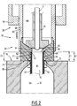
- FIG 2 there is described an assembly 30 of a preform 32 and a station 34 for hydroforming a container (not shown) from the preform.
- the assembly 30 is substantially symmetrical around the axial direction D.
- the station 34 comprises a mold 36 for receiving the preform 32, and an injection head 38 suitable for injecting a liquid into the preform in order to shape the preform into the container and advantageously also in order to fill in the container.
- the preform 32 and the preform 1 shown in figure 1 may be similar.
- the preform 32 comprises a hollow body 40 defining an inner volume 42, and a neck 44 extending along the axial direction D.
- the preform 32 may have a shape similar to that of a test tube being closed at a lower end along the axial direction D and having the neck 44 at an upper end.
- the preform 32 is made of any suitable plastic materials, such as polyesters, such as polyethylene terephthalate (PET), polyethylene naphthalate (PEN), polyethylene imine (PEI), polytrimethylene terephthalate (PTT), polylactic acid (PLA), polyethylene furanoate (PEF), or polyolefins, such as polyethylene low density (LDPE) or high density (HDPE), polypropylene (PP), or styrene based materials such as polystyrene (PS), acrylonitrile butadiene styrene (ABS) or other polymers, such as polyvinyl chloride (PVC).
- polyesters such as polyethylene terephthalate (PET), polyethylene naphthalate (PEN), polyethylene imine (PEI), polytrimethylene terephthalate (PTT), polylactic acid (PLA), polyethylene furanoate (PEF), or polyolefins, such as polyethylene low density (LDPE) or high density (
- the preform 32 is generally produced according to an injection molding process and molded at a site different from the site where the station 34 is located.
- the hollow body 40 is for example cylindrical and extends axially.
- the neck 44 generally has the final shape of the neck of the container to be produced.
- the neck 44 comprises a radially protruding support ring 46, and a finish 48 axially opposed to the support ring and defining an opening 50 of the preform 32 along the axial direction D.
- a lower surface of the support ring 46 defines a first contact surface 52 of the neck 44 with the station 38.
- the first contact surface 52 is for example substantially perpendicular to the axial direction D and has an annular shape surrounding the neck 44.
- the mold 36 for receiving the preform 32 defines a molding cavity 54 having the shape of the container to be produced.
- the mold 36 also defines a support surface 56 adapted to support the first contact surface 52 of the support ring 46.
- the mold 36 comprises for example at least two parts (not shown) movable relative to each other, between an open position, wherein the preform 32 can be placed in the mold and the formed container can be retrieved from the mold, wherein the two parts define together the molding cavity 54, and a closed position when the preform is placed in the mold, wherein said molding cavity is closed in a liquid tight manner.
- the two parts are for example hinged together and are movable in rotation relative to each other around an axis substantially parallel to the axial direction D.
- the injection head 38 comprises a head body 58 and an injection nozzle 60.
- the head body 58 is for example in a fixed axial position with respect to the mold 36.
- fixed it is meant that the head body 58 is immovable relative to the mold 36 along the axial direction D.
- the nozzle 60 comprises an end part 62 defining an outlet 64 for the liquid to be injected into the preform, and a nozzle body 66 attached to the end part, the nozzle body 66 and the end part 62 defining an internal chamber 68 for the liquid to be injected into the preform 32.
- the nozzle 60 also comprises a control rod 70 extending axially within the internal chamber 68 and movable axially with respect to the nozzle body between a closing position, in which an extremity of the control rod 70 is in liquid tight contact with the end part 62 in order to close the outlet 64, and an opening position, in which the control rod 70 is away from the end part 62 in order to let the liquid flow outside of the internal chamber 68.
- the injection nozzle 60 may further comprise a stretch rod 71 in the centre of the control rod 70.
- the stretch rod 71 is known per se and will not be described here.
- the nozzle 60 is movable along the axial direction D with respect to the mold 36 from a retracted position, wherein the nozzle is away from the neck 44, to an intermediate position, wherein a contact is established between a first contact surface 72 of the nozzle and the finish 48 of the neck 44, and further to an injection position (shown in figure 2 ), wherein a second contact surface 74 of the nozzle abuts on an abutment surface 76 and the neck 44 is axially compressed between the support surface 56 of the mold 36 and the first contact surface 72.
- the nozzle 60 is closer to the mold 36 in the injection position than in the intermediate position along the axial direction D.
- the axial distance between the intermediate position and the injection position is for example greater than 0.1 mm.
- the retracted position of the nozzle 60 can be obtained from figure 2 by moving the nozzle up along the axial direction D with respect to the mold 36, so that the end part 62 is away from the mold and the neck 44 to allow the mold to be opened.
- the intermediate position can be obtained from figure 2 by moving the nozzle 60 up along the axial direction D with respect to the mold 36, so that the end part 62 is away from both the mold, but still in contact with the neck 44 which expands axially between the support surface 56 of the mold and the first contact surface 72. In the intermediate position, the neck 44 is only in contact with the first surface 72 and is not compressed.
- the end part 62 is integral and for example made of metal.
- the end part 62 is for example screwed into the nozzle body 66 along the axial direction D.
- the end part 62 surrounds the neck 44 around the axial direction D.
- a space 77 is provided between the neck 44 and the interior of the end part 62. Said space may be used to host a sensor for example, or may be radially close enough from the thread extremity to limit the radial deformation of the neck 44 when a liquid under high pressure is injected into the preform 1.
- the first contact surface 72 is for example formed by an inner shoulder of the end part 62.
- the first contact surface 72 is advantageously substantially perpendicular to the axial direction D. Therefore the axial movement of the injection nozzle will not provoke radial or lateral deformation of the neck 44.
- the first contact surface 72 is less deformable than the neck 44 in the axial direction, meaning that the first contact surface 72 is not compressed in the axial direction when said first contact surface is applied against the finish 48 of the neck 44.
- the first contact surface 72 compresses no seal that would be more deformable than the neck 44 along the axial direction D.
- the second contact surface 74 is for example defined by a lower annular face of the end part 62, advantageously perpendicular to the axial direction D.
- the internal diameter ID of the second contact surface 74 is large enough so that the end part 62 does not abut against the support ring 46.
- the abutment surface 76 is for example defined by an upper face of the mold 36, and is advantageously perpendicular to the axial direction D.
- the neck 44 has an initial axial extension E1 when the nozzle 60 is in the retracted position, and has a reduced axial extension E2 when the nozzle is in the injection position.
- axial extension it is meant the length of the neck 44 along the axial direction D.
- the location of the abutment surface 76 along the axial direction D, and the axial distance E3 between the first contact surface 72 and the second contact surface 74 are adapted so that the difference between the initial axial extension E1 and the reduced axial extension E2 is greater than 0.1mm or ranges from 0.2 mm to 0.4 mm, and is preferably around 0.3 mm. This means that the length of the neck 44 in the axial direction D is reduced by 0.2 mm to 0.4 mm when the nozzle 60 is applied against the neck in the injection position.
- the nozzle body 66 is for example made of a hollow cylinder.
- the nozzle body 66 is axially movable with respect to the head body 58.
- the nozzle body 66 is axially movable within the head body 58 and displaced by a pneumatic system (not shown).
- the internal chamber 68 is in fluidic communication with a source (not show) of the liquid to be injected into the preform 32.
- the liquid to be injected in the preform 32 by the station 34 is for example the liquid that is intended to be in the container when the latter is used by an end user (not shown).
- the preform 32 is placed in the mold 36. To do so, the mold 36 is moved to its open position, the preform 32 is put in the mold, and the mold is moved back to its closed position.
- the first contact surface 52 of the support ring 46 lies on the support surface 56 of the mold 36.
- the neck 44 is outside of the cavity 54.
- the injection nozzle 60 is moved down along the axial direction D with respect to the head body 58 from the retracted position to the intermediate position. A contact is established between the first contact surface 72 of the end part 62 and the finish 48 of the neck 44.
- the neck 44 has its initial axial extension E1.
- the axial distance between the second contact surface 74 and the abutment surface 76 is equal to E1 minus E2.
- the nozzle 60 is further moved down axially until the second contact surface 74 of the end part 62 abuts against the abutment surface 76.
- the abutment surface 76 being fixed with respect to the mold 36, this stops the nozzle 60 in its injection position represented in figure 2 .
- the neck 44 is axially compressed progressively between the support surface 56 of the mold 36 and the first contact surface 72 of the end part 62.
- the axial extension of the neck 44 is E2.
- the reduction of the axial extension of the neck 44 is equal to E1 minus E2.
- the control rod 70 is then moved up in order to let the liquid flow from the internal chamber 68 of the nozzle 60 into the inner volume 42 of the preform 32.
- the liquid urges the hollow body 40 against the walls of the molding cavity 54.
- the liquid shapes the preform 32 into the container (not represented).
- the liquid is also the liquid that fills the container. In other words, the liquid will be contained in the container and is intended to be used by an end user (not represented).
- the finish 48 presses against the first contact surface 72, which prevents the liquid from flowing outwardly between the finish 48 and the first contact surface 72 and in the space between the neck and the interior of the end part 62.
- control rod 70 is again pressed against the end part 62 in order to seal the internal chamber 68.
- the nozzle 60 is moved up axially back to its retracted position.
- the neck 44 is not any more axially compressed and expands along the axial direction D, for example until its axial extension is equal to the initial axial extension E1.
- the end part 62 having a fixed axial extension E3, is adapted to provide the preform 32 with a given reduced axial extension E2.
- the end part 62 may be replaced by another end part having a different axial extension E3 between the first contact surface 72 and the second contact surface 74.
- the end part 62 is adapted to a given neck 44 having a given initial axial extension E1, and requesting a desired compression E1-E2 to act as a seal.
- the assembly 30 eliminates or at least greatly reduces the leak problems, while remaining economical and enabling a high production output. Furthermore, the pressure applied on the neck 44 by the nozzle 60 is precisely controlled, which reduces the risk of damaging the neck during the injection.
- the assembly 130 is analogous to the assembly 30 shown in figure 2 .
- the elements that are similar have the same numeral references and will not be described again. Only the differences will be described in detail hereafter.
- the injection nozzle 60 of the assembly 130 comprises an end part 162 which differs from the end part 62 shown in figure 2 .
- the end part 162 includes a distal part 164 defining the second contact surface 74, a proximal part 166, and a laminated shim 168 interposed between the distal part and the proximal part along the axial direction D.
- distal part 164 is screwed on the proximal part 166 along the axial direction D.
- a lower surface of the proximal part 166 defines the first contact surface 72.
- the laminated shim 168 is for example located axially between a fourth contact surface 170 of the distal part 164 and the first contact surface 72.
- Such a laminated shim 168 is made of several layers of material and its extension or length in the axial direction D is adjustable by removing one or more layers of the laminated shim.
- the layers are for example peelable layers.
- the fourth contact surface 170 if advantageously substantially perpendicular to the axial direction D.
- the laminated shim 168 is adapted for adjusting the axial distance E3 between the first contact surface 72 and the third contact 74 surface by varying an extension E4 of the shim 168 along the axial direction D.
- the assembly 130 is used in the same manner as the assembly 30, except that the end part 162 does not have to be replaced by another end part in case another preform 32 with a different neck 44 has to be shaped.
- the assembly 230 is analogous to the assembly 30 shown in figure 2 .
- the elements that are similar have the same numeral references and will not be described again. Only the differences will be described in detail hereafter.
- the abutment surface is not defined by the mold 36.
- the head body 58 comprises a stop element 258 defining a stop which defines an abutment surface 276.
- the abutment surface 276 is defined by an upper face of a lower part of the stop element 258 along the axial direction D.
- the stop element 258 is for example rigidly fixed to the head body 58 at least during the injection and advantageously axially adjustable with respect to the head body 58 so as to make the assembly 230 cope with different initial axial extensions E1 of the neck 44.
- an assembly 330 will now be described in reference to figure 5 .
- the assembly 330 is analogous to the assembly 30 shown in figure 2 .
- the elements that are similar have the same numeral references and will not be described again. Only the differences will be described in detail hereafter.
- the end part 62 is adapted to abut against an upper face of the support ring 46.
- the support ring 46 defines an abutment surface 376.
- the abutment surface 376 is opposed to the first contact surface 52 of the support ring 46 along the axial direction D.
- the internal diameter ID of the second contact surface 74 is smaller than the external diameter of the support ring 46.
- the lower part of the end part 62 is advantageously truncated along the axial direction D with a narrowing radial dimension towards the second contact surface 74.
- the support ring 46 being somewhat incompressible axially, its upper surface manages to act as an abutment surface for the end part 62.
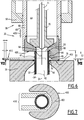
- a variant illustrated in figures 6 and 7 defers from the first and second embodiments by the shape of the contact between the injection nozzle 60 and the mold 36.
- the end part 62 of the first embodiment or the distal part 164 of the second embodiment are replaced by a side part 400 providing a second surface 402 which is not annular.
- a pair of grippers 410 that are generally not included in the forming station shown in figure 6 , can access around the neck 44 from a free side of the neck.
- the grippers 410 are connected to the neck 44 at an axial position located between the support ring 46 and a holding ring 47.
- the second contact surface 402 is limited to the space left free by the grippers 410 connected with the neck 44.
- Such a variant has the same advantages as the first and the second embodiments, providing a robust direct stop of the injection nozzle 60 against the mold 36, together with a reliable sealing on the finish 48 and a robust and easy to clean contact surfaces.
- the variant provides an additional advantage. It allows a reduction of the length and the duration of the axial movement requested for the injection nozzle 60. Said axial movement is indicated by the arrow 420. This reduces the transition step of the forming process and allows higher throughputs of the forming station.
- the assemblies and methods can also be adapted for a non vertical axial direction D.
Claims (15)
- Ensemble (30 ; 130 ; 230 ; 330) composé d'une préforme (32) et d'un poste (34) d'hydroformage d'un conteneur à partir de la préforme (32), dans lequel :- la préforme (32) possède une encolure (44) s'étendant le long d'une direction axiale (D), l'encolure (44) comprenant une bague de support (46) sortant radialement, et une finition (48) axialement opposée à la bague de support (46),- le poste (34) comprend un moule (36) dans lequel la préforme (32) est placée, la bague de support (46) étant en contact avec une surface de support (56) du moule (36),- le poste (34) comprend une buse d'injection (60) qui est mobile le long de la direction axiale (D) par rapport au moule (36) entre une position rétractée, dans laquelle la buse (60) est éloignée de l'encolure (44) et une position intermédiaire, et une position d'éjection,caractérisé en ce que :- dans la position intermédiaire, un contact est établi entre une première surface de contact (72) de la buse (60) et la finition (48),- dans la position d'injection, une seconde surface de contact (74) de la buse (60) bute contre une surface de butée (76 ; 276 ; 376) et l'encolure (44) est axialement compressée entre la surface de support (56) et la première surface de contact (72), la première surface de contact (72) étant moins déformable que l'encolure (44) dans la direction axiale (D), et- le poste (34) est adapté pour injecter un liquide, depuis la buse (60), dans la préforme (32) lorsque la buse (60) est en position d'injection, et la surface de butée (76, 276) est fixe le long de la direction axiale (D) par rapport au moule (36), au moins pendant l'injection.
- Ensemble (30 ; 130 ; 230 ; 330) selon la revendication 1, dans lequel la buse (60) dans la position d'injection est plus proche du moule (36) que dans la position intermédiaire, et la distance axiale entre la position intermédiaire et la position d'injection est supérieure à 0,1mm.
- Ensemble (30 ; 130 ; 230 ; 330) selon la revendication 1 ou 2, dans lequel :- l'encolure (44) possède une extension axiale initiale (E1) lorsque la buse (60) se trouve dans la position rétractée, et possède une extension radiale réduite (E2) lorsque la buse (60) se trouve dans la position d'injection, et- l'emplacement de la surface de butée (76 ; 276 ; 376) le long de la direction axiale (D), et la distance axiale (E3) entre la première surface de contact (72) et la seconde surface de contact (74) sont adaptés de sorte que la différence entre l'extension axiale initiale (E1) et l'extension axiale réduite (E2) soit comprise entre 0,2 mm et 0,4 mm, et se situe de préférence autour de 0,3 mm.
- Ensemble (30 ; 130 ; 230 ; 330) selon l'une quelconque des revendications 1 à 3, dans lequel la buse (60) comprend au moins une partie d'extrémité (62 ; 162) composée d'un métal et définissant la première surface de contact (72).
- Ensemble (30 ; 130 ; 230 ; 330) selon la revendication 4, dans lequel la partie d'extrémité (62 ; 162) fait partie intégrante de et définit en outre la seconde surface de contact (74).
- Ensemble (130) selon l'une quelconque des revendications 4 ou 5, dans lequel la partie d'extrémité (162) comprend une partie distale (164) définissant la seconde surface de contact (74), une partie proximale (166), et une cale stratifiée (168) située entre la partie distale (164) et la partie proximale (166) le long de la direction axiale (D), la cale stratifiée (168) étant adaptée pour ajuster la distance axiale (E3) entre la première surface de contact (72) et la seconde surface de contact (74) en faisant varier la dimension axiale (E4) de la cale (168).
- Ensemble (30 ; 130) selon l'une quelconque des revendications 1 à 6, dans lequel la surface de butée (76) est définie par le moule (36).
- Ensemble (330) selon l'une quelconque des revendications 1 à 6, dans lequel la surface de butée (376) est définie par la bague de support (46), la surface de butée (376) étant axialement opposée à une surface de contact (52) de la bague de support (46), la surface de contact (52) étant en contact avec la surface de support (56) du moule.
- Ensemble (230) selon l'une quelconque des revendications 1 à 6, comprenant en outre une tête d'injection (38) comprenant un corps de tête (58) ayant une position axiale fixe par rapport au moule (36) au moins pendant que la buse d'injection est en position d'injection, la buse d'injection (60) étant axialement mobile par rapport au corps de tête (58).
- Ensemble (230) selon la revendication 9, dans lequel la surface de butée (276) est définie par une butée dans le corps de tête (58).
- Ensemble (230) selon la revendication 9, dans lequel la surface de butée (276) est définie par un élément de butée (258) fixé de manière rigide sur le corps de tête (58) au moins pendant que la buse d'injection se trouve dans la position d'injection, et axialement réglable par rapport au corps de tête de façon à adapter l'ensemble (230) à différentes extensions axiales initiales (E1) de l'encolure (44).
- Ensemble (30 ; 130 ; 230 ; 330) selon l'une quelconque des revendications 1 à 11, dans lequel la première surface de contact (72) de la buse (60) est perpendiculaire à la direction axiale (D).
- Ensemble (30 ; 130) selon l'une quelconque des revendications 1 à 12, dans lequel la seconde surface de contact (402) de la buse (60) s'étend latéralement depuis l'encolure (44) ou possède une forme de C autour de l'encolure (44), de façon à permettre un accès à l'encolure (44) depuis un côté libre de l'encolure (44) pendant que la buse d'injection (60) se trouve en position intermédiaire.
- Procédé d'hydroformage d'un conteneur à partir d'une préforme (32) ayant une encolure (44) s'étendant le long d'une direction axiale (D), l'encolure (44) comprenant une bague de support (46) sortant radialement, et une finition (48) axialement opposée à la bague de support (46), le procédé comprenant les étapes consistant à :- placer la préforme (32) dans un moule (36) de sorte que la bague de support (46) soit en contact avec une surface de support (56) du moule (36),- déplacer une buse d'injection (60) le long de la direction axiale (D) par rapport au moule (36) depuis une position rétractée dans laquelle la buse (60) est éloignée de l'encolure (44), dans une position intermédiaire dans laquelle un contact est établi entre une première surface de contact (72) de la buse (60) et la finition (48),- le déplacement de la buse (60) axialement entre la position intermédiaire et une position d'injection, dans laquelle une seconde surface de contact (74) de la buse (60) bute contre une surface de butée (76 ; 276 ; 376) et l'encolure (44) est axialement compressée entre la surface de support (56) et la première surface de contact (72), la première surface de contact (72) étant moins déformable que l'encolure (44) dans la direction axiale (D), et- l'injection d'un liquide depuis la buse (60), dans la préforme (32), la buse (60) étant dans la position d'injection, la surface de butée (76 ; 276 ; 376) étant fixe le long de la direction axiale (D) par rapport au moule (36) au moins pendant ladite injection.
- Procédé selon la revendication 14, dans lequel l'encolure (44) possède une extension axiale initiale (E1) lorsque la buse (60) est en position rétractée, et possède une extension axiale réduite (E2) lorsque la buse (60) se trouve dans la position d'injection, l'emplacement de la surface de butée (76 ; 276 ; 376) le long de la direction axiale (D) et la distance axiale (E3) entre la première surface de contact (72) et la seconde surface de contact (74) étant adaptés de sorte que la différence entre l'extension axiale initiale (E1) et l'extension axiale réduite (E2) soit supérieure à 0,1 mm, et soit de préférence comprise entre 0,2 mm et 0,4 mm, et se situe de préférence autour de 0,3 mm,
et/ou dans lequel la distance axiale le long de laquelle la buse d'injection (60) est déplacée pendant ledit déplacement de la buse de la position intermédiaire vers la position d'injection est supérieure à 0,1 mm, de préférence comprise entre 0,2 mm et 0,4 mm, et se situe de préférence autour de 0,3 mm.
Priority Applications (4)
| Application Number | Priority Date | Filing Date | Title |
|---|---|---|---|
| EP14305658.8A EP2942177B1 (fr) | 2014-05-05 | 2014-05-05 | Procédé d'hydroformage d'un récipient à partir d'une préforme |
| US14/703,492 US9889596B2 (en) | 2014-05-05 | 2015-05-04 | Method for hydroforming a container from a preform |
| JP2015094919A JP6605838B2 (ja) | 2014-05-05 | 2015-05-07 | 予成形品から容器を液圧成形する方法 |
| US15/871,701 US10183439B2 (en) | 2014-05-04 | 2018-01-15 | Method for hydroforming a container from a preform |
Applications Claiming Priority (1)
| Application Number | Priority Date | Filing Date | Title |
|---|---|---|---|
| EP14305658.8A EP2942177B1 (fr) | 2014-05-05 | 2014-05-05 | Procédé d'hydroformage d'un récipient à partir d'une préforme |
Publications (2)
| Publication Number | Publication Date |
|---|---|
| EP2942177A1 EP2942177A1 (fr) | 2015-11-11 |
| EP2942177B1 true EP2942177B1 (fr) | 2017-07-12 |
Family
ID=50693593
Family Applications (1)
| Application Number | Title | Priority Date | Filing Date |
|---|---|---|---|
| EP14305658.8A Active EP2942177B1 (fr) | 2014-05-04 | 2014-05-05 | Procédé d'hydroformage d'un récipient à partir d'une préforme |
Country Status (3)
| Country | Link |
|---|---|
| US (2) | US9889596B2 (fr) |
| EP (1) | EP2942177B1 (fr) |
| JP (1) | JP6605838B2 (fr) |
Families Citing this family (6)
| Publication number | Priority date | Publication date | Assignee | Title |
|---|---|---|---|---|
| JP6632872B2 (ja) * | 2015-11-27 | 2020-01-22 | 株式会社吉野工業所 | 液体ブロー成形方法 |
| JP6661366B2 (ja) | 2015-12-17 | 2020-03-11 | 株式会社吉野工業所 | 容器製造方法 |
| JP6809835B2 (ja) | 2016-08-03 | 2021-01-06 | 株式会社吉野工業所 | 液体ブロー成形方法 |
| JP6809846B2 (ja) * | 2016-08-31 | 2021-01-06 | 株式会社吉野工業所 | 液体ブロー成形方法 |
| KR101780006B1 (ko) | 2017-02-20 | 2017-09-19 | 강대웅 | 바틀링 사출금형장치 및 바틀링이 구비된 젖병용기 |
| US11198243B2 (en) | 2018-01-11 | 2021-12-14 | Husky Injection Molding Systems Ltd. | Method and apparatus for forming final-shaped containers using liquid to be contained therein |
Family Cites Families (10)
| Publication number | Priority date | Publication date | Assignee | Title |
|---|---|---|---|---|
| CH683757A5 (fr) * | 1990-05-31 | 1994-05-13 | Dynaplast Sa | Machine modulaire intégrée pour la fabrication et le conditionnement de récipients en téréphtalate de polyéthylène bi-orienté et les modules de soufflage et remplissage la constituant. |
| FR2705272B1 (fr) * | 1993-05-19 | 1995-07-28 | Sidel Sa | Procédé et agencement pour positionner angulairement un récipient ou une préforme de récipient sur un mandrin introduit dans le goulot de celui-ci, et mandrin et récipient associés. |
| US7914726B2 (en) * | 2006-04-13 | 2011-03-29 | Amcor Limited | Liquid or hydraulic blow molding |
| JP5206372B2 (ja) * | 2007-12-17 | 2013-06-12 | 東洋製罐株式会社 | 樹脂製容器の製造方法、及びブロー成形装置 |
| DE102008036103A1 (de) * | 2008-08-04 | 2010-02-11 | Krones Ag | Vorrichtung zum Expandieren von Behältnissen |
| EP2463079A1 (fr) * | 2010-12-10 | 2012-06-13 | Nestec S.A. | Procédé de formation à étape unique et de remplissage de conteneurs |
| AU2012217948B2 (en) * | 2011-02-16 | 2017-02-23 | Discma Ag | Blow nozzle to control liquid flow with pre-stretch rod assembly and metal seat seal pin |
| CN104023941B (zh) * | 2011-10-27 | 2017-02-01 | 帝斯克玛股份有限公司 | 形成并填充容器的方法及设备 |
| BR112014015428B1 (pt) * | 2011-12-21 | 2020-11-17 | Amcor Limited | sistema de vedação para máquina de moldagem |
| JP5747412B2 (ja) * | 2011-12-27 | 2015-07-15 | 株式会社吉野工業所 | ブロー成形装置及び容器の製造方法 |
-
2014
- 2014-05-05 EP EP14305658.8A patent/EP2942177B1/fr active Active
-
2015
- 2015-05-04 US US14/703,492 patent/US9889596B2/en active Active
- 2015-05-07 JP JP2015094919A patent/JP6605838B2/ja active Active
-
2018
- 2018-01-15 US US15/871,701 patent/US10183439B2/en active Active
Non-Patent Citations (1)
| Title |
|---|
| None * |
Also Published As
| Publication number | Publication date |
|---|---|
| EP2942177A1 (fr) | 2015-11-11 |
| US10183439B2 (en) | 2019-01-22 |
| US20180133949A1 (en) | 2018-05-17 |
| US9889596B2 (en) | 2018-02-13 |
| US20150314518A1 (en) | 2015-11-05 |
| JP2015212083A (ja) | 2015-11-26 |
| JP6605838B2 (ja) | 2019-11-13 |
Similar Documents
| Publication | Publication Date | Title |
|---|---|---|
| US10183439B2 (en) | Method for hydroforming a container from a preform | |
| EP3110609B1 (fr) | Dispositif d'injection comprenant au moins un diaphragme flexible et méthode de formage et de remplissage utilisant ledit dispositif | |
| WO2015136368A2 (fr) | Procédé de formation et de réglage de l'espace libre dans un récipient | |
| EP2801468B1 (fr) | Appareil et procédé de fabrication des récipients | |
| EP3647017B1 (fr) | Méthode de fabrication d'un récipient rempli de liquide | |
| JP6909170B2 (ja) | ブロー成形装置 | |
| EP3292984B1 (fr) | Appareil de moulage par soufflage de liquide et procédé de moulage par soufflage de liquide | |
| US10183438B2 (en) | Apparatus and method for fabricating containers | |
| CN109803808B (zh) | 液体吹塑成型系统 | |
| EP3377297B1 (fr) | Procédé pour former un récipient à l'aide d'un liquide | |
| EP3278953B1 (fr) | Appareil de moulage par soufflage de liquide | |
| EP3377299B1 (fr) | Procédé de pilotage d'un systeme de moulage |
Legal Events
| Date | Code | Title | Description |
|---|---|---|---|
| PUAI | Public reference made under article 153(3) epc to a published international application that has entered the european phase |
Free format text: ORIGINAL CODE: 0009012 |
|
| AK | Designated contracting states |
Kind code of ref document: A1 Designated state(s): AL AT BE BG CH CY CZ DE DK EE ES FI FR GB GR HR HU IE IS IT LI LT LU LV MC MK MT NL NO PL PT RO RS SE SI SK SM TR |
|
| AX | Request for extension of the european patent |
Extension state: BA ME |
|
| 17P | Request for examination filed |
Effective date: 20160509 |
|
| RBV | Designated contracting states (corrected) |
Designated state(s): AL AT BE BG CH CY CZ DE DK EE ES FI FR GB GR HR HU IE IS IT LI LT LU LV MC MK MT NL NO PL PT RO RS SE SI SK SM TR |
|
| GRAP | Despatch of communication of intention to grant a patent |
Free format text: ORIGINAL CODE: EPIDOSNIGR1 |
|
| RIC1 | Information provided on ipc code assigned before grant |
Ipc: B29C 49/46 20060101ALN20161111BHEP Ipc: B29C 49/58 20060101ALI20161111BHEP Ipc: B29C 49/06 20060101ALN20161111BHEP Ipc: B29C 49/42 20060101ALI20161111BHEP Ipc: B29C 49/28 20060101AFI20161111BHEP Ipc: B29L 31/00 20060101ALN20161111BHEP Ipc: B29C 49/76 20060101ALI20161111BHEP Ipc: B29C 49/12 20060101ALN20161111BHEP |
|
| INTG | Intention to grant announced |
Effective date: 20161129 |
|
| RIC1 | Information provided on ipc code assigned before grant |
Ipc: B29C 49/42 20060101ALI20161118BHEP Ipc: B29C 49/28 20060101AFI20161118BHEP Ipc: B29L 31/00 20060101ALN20161118BHEP Ipc: B29C 49/76 20060101ALI20161118BHEP Ipc: B29C 49/46 20060101ALN20161118BHEP Ipc: B29C 49/06 20060101ALN20161118BHEP Ipc: B29C 49/58 20060101ALI20161118BHEP Ipc: B29C 49/12 20060101ALN20161118BHEP |
|
| GRAJ | Information related to disapproval of communication of intention to grant by the applicant or resumption of examination proceedings by the epo deleted |
Free format text: ORIGINAL CODE: EPIDOSDIGR1 |
|
| REG | Reference to a national code |
Ref country code: DE Ref legal event code: R079 Ref document number: 602014011694 Country of ref document: DE Free format text: PREVIOUS MAIN CLASS: B29C0049460000 Ipc: B29C0049280000 |
|
| GRAP | Despatch of communication of intention to grant a patent |
Free format text: ORIGINAL CODE: EPIDOSNIGR1 |
|
| INTC | Intention to grant announced (deleted) | ||
| RIC1 | Information provided on ipc code assigned before grant |
Ipc: B29C 49/46 20060101ALN20170124BHEP Ipc: B29C 49/42 20060101ALI20170124BHEP Ipc: B29C 49/58 20060101ALI20170124BHEP Ipc: B29C 49/06 20060101ALN20170124BHEP Ipc: B29L 31/00 20060101ALN20170124BHEP Ipc: B29C 49/12 20060101ALN20170124BHEP Ipc: B29C 49/28 20060101AFI20170124BHEP Ipc: B29C 49/76 20060101ALI20170124BHEP |
|
| INTG | Intention to grant announced |
Effective date: 20170210 |
|
| RIC1 | Information provided on ipc code assigned before grant |
Ipc: B29C 49/42 20060101ALI20170201BHEP Ipc: B29C 49/12 20060101ALN20170201BHEP Ipc: B29C 49/76 20060101ALI20170201BHEP Ipc: B29C 49/06 20060101ALN20170201BHEP Ipc: B29C 49/58 20060101ALI20170201BHEP Ipc: B29C 49/46 20060101ALN20170201BHEP Ipc: B29L 31/00 20060101ALN20170201BHEP Ipc: B29C 49/28 20060101AFI20170201BHEP |
|
| GRAS | Grant fee paid |
Free format text: ORIGINAL CODE: EPIDOSNIGR3 |
|
| GRAA | (expected) grant |
Free format text: ORIGINAL CODE: 0009210 |
|
| AK | Designated contracting states |
Kind code of ref document: B1 Designated state(s): AL AT BE BG CH CY CZ DE DK EE ES FI FR GB GR HR HU IE IS IT LI LT LU LV MC MK MT NL NO PL PT RO RS SE SI SK SM TR |
|
| REG | Reference to a national code |
Ref country code: GB Ref legal event code: FG4D |
|
| REG | Reference to a national code |
Ref country code: CH Ref legal event code: EP Ref country code: CH Ref legal event code: NV Representative=s name: ARNOLD AND SIEDSMA AG, CH |
|
| REG | Reference to a national code |
Ref country code: AT Ref legal event code: REF Ref document number: 907919 Country of ref document: AT Kind code of ref document: T Effective date: 20170715 |
|
| REG | Reference to a national code |
Ref country code: IE Ref legal event code: FG4D |
|
| REG | Reference to a national code |
Ref country code: DE Ref legal event code: R096 Ref document number: 602014011694 Country of ref document: DE |
|
| REG | Reference to a national code |
Ref country code: NL Ref legal event code: MP Effective date: 20170712 |
|
| REG | Reference to a national code |
Ref country code: LT Ref legal event code: MG4D |
|
| REG | Reference to a national code |
Ref country code: AT Ref legal event code: MK05 Ref document number: 907919 Country of ref document: AT Kind code of ref document: T Effective date: 20170712 |
|
| PG25 | Lapsed in a contracting state [announced via postgrant information from national office to epo] |
Ref country code: NO Free format text: LAPSE BECAUSE OF FAILURE TO SUBMIT A TRANSLATION OF THE DESCRIPTION OR TO PAY THE FEE WITHIN THE PRESCRIBED TIME-LIMIT Effective date: 20171012 Ref country code: HR Free format text: LAPSE BECAUSE OF FAILURE TO SUBMIT A TRANSLATION OF THE DESCRIPTION OR TO PAY THE FEE WITHIN THE PRESCRIBED TIME-LIMIT Effective date: 20170712 Ref country code: FI Free format text: LAPSE BECAUSE OF FAILURE TO SUBMIT A TRANSLATION OF THE DESCRIPTION OR TO PAY THE FEE WITHIN THE PRESCRIBED TIME-LIMIT Effective date: 20170712 Ref country code: AT Free format text: LAPSE BECAUSE OF FAILURE TO SUBMIT A TRANSLATION OF THE DESCRIPTION OR TO PAY THE FEE WITHIN THE PRESCRIBED TIME-LIMIT Effective date: 20170712 Ref country code: NL Free format text: LAPSE BECAUSE OF FAILURE TO SUBMIT A TRANSLATION OF THE DESCRIPTION OR TO PAY THE FEE WITHIN THE PRESCRIBED TIME-LIMIT Effective date: 20170712 Ref country code: SE Free format text: LAPSE BECAUSE OF FAILURE TO SUBMIT A TRANSLATION OF THE DESCRIPTION OR TO PAY THE FEE WITHIN THE PRESCRIBED TIME-LIMIT Effective date: 20170712 Ref country code: LT Free format text: LAPSE BECAUSE OF FAILURE TO SUBMIT A TRANSLATION OF THE DESCRIPTION OR TO PAY THE FEE WITHIN THE PRESCRIBED TIME-LIMIT Effective date: 20170712 |
|
| PG25 | Lapsed in a contracting state [announced via postgrant information from national office to epo] |
Ref country code: ES Free format text: LAPSE BECAUSE OF FAILURE TO SUBMIT A TRANSLATION OF THE DESCRIPTION OR TO PAY THE FEE WITHIN THE PRESCRIBED TIME-LIMIT Effective date: 20170712 Ref country code: LV Free format text: LAPSE BECAUSE OF FAILURE TO SUBMIT A TRANSLATION OF THE DESCRIPTION OR TO PAY THE FEE WITHIN THE PRESCRIBED TIME-LIMIT Effective date: 20170712 Ref country code: PL Free format text: LAPSE BECAUSE OF FAILURE TO SUBMIT A TRANSLATION OF THE DESCRIPTION OR TO PAY THE FEE WITHIN THE PRESCRIBED TIME-LIMIT Effective date: 20170712 Ref country code: BG Free format text: LAPSE BECAUSE OF FAILURE TO SUBMIT A TRANSLATION OF THE DESCRIPTION OR TO PAY THE FEE WITHIN THE PRESCRIBED TIME-LIMIT Effective date: 20171012 Ref country code: IS Free format text: LAPSE BECAUSE OF FAILURE TO SUBMIT A TRANSLATION OF THE DESCRIPTION OR TO PAY THE FEE WITHIN THE PRESCRIBED TIME-LIMIT Effective date: 20171112 Ref country code: GR Free format text: LAPSE BECAUSE OF FAILURE TO SUBMIT A TRANSLATION OF THE DESCRIPTION OR TO PAY THE FEE WITHIN THE PRESCRIBED TIME-LIMIT Effective date: 20171013 Ref country code: RS Free format text: LAPSE BECAUSE OF FAILURE TO SUBMIT A TRANSLATION OF THE DESCRIPTION OR TO PAY THE FEE WITHIN THE PRESCRIBED TIME-LIMIT Effective date: 20170712 |
|
| REG | Reference to a national code |
Ref country code: DE Ref legal event code: R097 Ref document number: 602014011694 Country of ref document: DE |
|
| REG | Reference to a national code |
Ref country code: FR Ref legal event code: PLFP Year of fee payment: 5 |
|
| PG25 | Lapsed in a contracting state [announced via postgrant information from national office to epo] |
Ref country code: DK Free format text: LAPSE BECAUSE OF FAILURE TO SUBMIT A TRANSLATION OF THE DESCRIPTION OR TO PAY THE FEE WITHIN THE PRESCRIBED TIME-LIMIT Effective date: 20170712 Ref country code: CZ Free format text: LAPSE BECAUSE OF FAILURE TO SUBMIT A TRANSLATION OF THE DESCRIPTION OR TO PAY THE FEE WITHIN THE PRESCRIBED TIME-LIMIT Effective date: 20170712 Ref country code: RO Free format text: LAPSE BECAUSE OF FAILURE TO SUBMIT A TRANSLATION OF THE DESCRIPTION OR TO PAY THE FEE WITHIN THE PRESCRIBED TIME-LIMIT Effective date: 20170712 |
|
| PLBE | No opposition filed within time limit |
Free format text: ORIGINAL CODE: 0009261 |
|
| STAA | Information on the status of an ep patent application or granted ep patent |
Free format text: STATUS: NO OPPOSITION FILED WITHIN TIME LIMIT |
|
| PG25 | Lapsed in a contracting state [announced via postgrant information from national office to epo] |
Ref country code: SK Free format text: LAPSE BECAUSE OF FAILURE TO SUBMIT A TRANSLATION OF THE DESCRIPTION OR TO PAY THE FEE WITHIN THE PRESCRIBED TIME-LIMIT Effective date: 20170712 Ref country code: SM Free format text: LAPSE BECAUSE OF FAILURE TO SUBMIT A TRANSLATION OF THE DESCRIPTION OR TO PAY THE FEE WITHIN THE PRESCRIBED TIME-LIMIT Effective date: 20170712 Ref country code: EE Free format text: LAPSE BECAUSE OF FAILURE TO SUBMIT A TRANSLATION OF THE DESCRIPTION OR TO PAY THE FEE WITHIN THE PRESCRIBED TIME-LIMIT Effective date: 20170712 |
|
| 26N | No opposition filed |
Effective date: 20180413 |
|
| PG25 | Lapsed in a contracting state [announced via postgrant information from national office to epo] |
Ref country code: SI Free format text: LAPSE BECAUSE OF FAILURE TO SUBMIT A TRANSLATION OF THE DESCRIPTION OR TO PAY THE FEE WITHIN THE PRESCRIBED TIME-LIMIT Effective date: 20170712 |
|
| GBPC | Gb: european patent ceased through non-payment of renewal fee |
Effective date: 20180505 |
|
| REG | Reference to a national code |
Ref country code: BE Ref legal event code: MM Effective date: 20180531 |
|
| PG25 | Lapsed in a contracting state [announced via postgrant information from national office to epo] |
Ref country code: MC Free format text: LAPSE BECAUSE OF FAILURE TO SUBMIT A TRANSLATION OF THE DESCRIPTION OR TO PAY THE FEE WITHIN THE PRESCRIBED TIME-LIMIT Effective date: 20170712 |
|
| REG | Reference to a national code |
Ref country code: IE Ref legal event code: MM4A |
|
| PG25 | Lapsed in a contracting state [announced via postgrant information from national office to epo] |
Ref country code: LU Free format text: LAPSE BECAUSE OF NON-PAYMENT OF DUE FEES Effective date: 20180505 |
|
| PG25 | Lapsed in a contracting state [announced via postgrant information from national office to epo] |
Ref country code: GB Free format text: LAPSE BECAUSE OF NON-PAYMENT OF DUE FEES Effective date: 20180505 Ref country code: IE Free format text: LAPSE BECAUSE OF NON-PAYMENT OF DUE FEES Effective date: 20180505 |
|
| PG25 | Lapsed in a contracting state [announced via postgrant information from national office to epo] |
Ref country code: BE Free format text: LAPSE BECAUSE OF NON-PAYMENT OF DUE FEES Effective date: 20180531 |
|
| PG25 | Lapsed in a contracting state [announced via postgrant information from national office to epo] |
Ref country code: MT Free format text: LAPSE BECAUSE OF NON-PAYMENT OF DUE FEES Effective date: 20180505 |
|
| PG25 | Lapsed in a contracting state [announced via postgrant information from national office to epo] |
Ref country code: TR Free format text: LAPSE BECAUSE OF FAILURE TO SUBMIT A TRANSLATION OF THE DESCRIPTION OR TO PAY THE FEE WITHIN THE PRESCRIBED TIME-LIMIT Effective date: 20170712 |
|
| PG25 | Lapsed in a contracting state [announced via postgrant information from national office to epo] |
Ref country code: PT Free format text: LAPSE BECAUSE OF FAILURE TO SUBMIT A TRANSLATION OF THE DESCRIPTION OR TO PAY THE FEE WITHIN THE PRESCRIBED TIME-LIMIT Effective date: 20170712 |
|
| PG25 | Lapsed in a contracting state [announced via postgrant information from national office to epo] |
Ref country code: CY Free format text: LAPSE BECAUSE OF FAILURE TO SUBMIT A TRANSLATION OF THE DESCRIPTION OR TO PAY THE FEE WITHIN THE PRESCRIBED TIME-LIMIT Effective date: 20170712 Ref country code: MK Free format text: LAPSE BECAUSE OF NON-PAYMENT OF DUE FEES Effective date: 20170712 Ref country code: HU Free format text: LAPSE BECAUSE OF FAILURE TO SUBMIT A TRANSLATION OF THE DESCRIPTION OR TO PAY THE FEE WITHIN THE PRESCRIBED TIME-LIMIT; INVALID AB INITIO Effective date: 20140505 |
|
| PG25 | Lapsed in a contracting state [announced via postgrant information from national office to epo] |
Ref country code: AL Free format text: LAPSE BECAUSE OF FAILURE TO SUBMIT A TRANSLATION OF THE DESCRIPTION OR TO PAY THE FEE WITHIN THE PRESCRIBED TIME-LIMIT Effective date: 20170712 |
|
| P01 | Opt-out of the competence of the unified patent court (upc) registered |
Effective date: 20230524 |
|
| PGFP | Annual fee paid to national office [announced via postgrant information from national office to epo] |
Ref country code: IT Payment date: 20230420 Year of fee payment: 10 Ref country code: FR Payment date: 20230420 Year of fee payment: 10 Ref country code: DE Payment date: 20230419 Year of fee payment: 10 Ref country code: CH Payment date: 20230602 Year of fee payment: 10 |