EP2942002A1 - Endoscope - Google Patents
Endoscope Download PDFInfo
- Publication number
- EP2942002A1 EP2942002A1 EP14817290.1A EP14817290A EP2942002A1 EP 2942002 A1 EP2942002 A1 EP 2942002A1 EP 14817290 A EP14817290 A EP 14817290A EP 2942002 A1 EP2942002 A1 EP 2942002A1
- Authority
- EP
- European Patent Office
- Prior art keywords
- distal end
- holding frame
- light guide
- hole
- guide
- Prior art date
- Legal status (The legal status is an assumption and is not a legal conclusion. Google has not performed a legal analysis and makes no representation as to the accuracy of the status listed.)
- Withdrawn
Links
Images


Classifications
-
- A—HUMAN NECESSITIES
- A61—MEDICAL OR VETERINARY SCIENCE; HYGIENE
- A61B—DIAGNOSIS; SURGERY; IDENTIFICATION
- A61B1/00—Instruments for performing medical examinations of the interior of cavities or tubes of the body by visual or photographical inspection, e.g. endoscopes; Illuminating arrangements therefor
- A61B1/06—Instruments for performing medical examinations of the interior of cavities or tubes of the body by visual or photographical inspection, e.g. endoscopes; Illuminating arrangements therefor with illuminating arrangements
-
- A—HUMAN NECESSITIES
- A61—MEDICAL OR VETERINARY SCIENCE; HYGIENE
- A61B—DIAGNOSIS; SURGERY; IDENTIFICATION
- A61B1/00—Instruments for performing medical examinations of the interior of cavities or tubes of the body by visual or photographical inspection, e.g. endoscopes; Illuminating arrangements therefor
- A61B1/00064—Constructional details of the endoscope body
- A61B1/00071—Insertion part of the endoscope body
- A61B1/0008—Insertion part of the endoscope body characterised by distal tip features
-
- A—HUMAN NECESSITIES
- A61—MEDICAL OR VETERINARY SCIENCE; HYGIENE
- A61B—DIAGNOSIS; SURGERY; IDENTIFICATION
- A61B1/00—Instruments for performing medical examinations of the interior of cavities or tubes of the body by visual or photographical inspection, e.g. endoscopes; Illuminating arrangements therefor
- A61B1/00064—Constructional details of the endoscope body
- A61B1/00071—Insertion part of the endoscope body
-
- A—HUMAN NECESSITIES
- A61—MEDICAL OR VETERINARY SCIENCE; HYGIENE
- A61B—DIAGNOSIS; SURGERY; IDENTIFICATION
- A61B1/00—Instruments for performing medical examinations of the interior of cavities or tubes of the body by visual or photographical inspection, e.g. endoscopes; Illuminating arrangements therefor
- A61B1/00064—Constructional details of the endoscope body
- A61B1/0011—Manufacturing of endoscope parts
-
- A—HUMAN NECESSITIES
- A61—MEDICAL OR VETERINARY SCIENCE; HYGIENE
- A61B—DIAGNOSIS; SURGERY; IDENTIFICATION
- A61B1/00—Instruments for performing medical examinations of the interior of cavities or tubes of the body by visual or photographical inspection, e.g. endoscopes; Illuminating arrangements therefor
- A61B1/00163—Optical arrangements
- A61B1/00165—Optical arrangements with light-conductive means, e.g. fibre optics
-
- A—HUMAN NECESSITIES
- A61—MEDICAL OR VETERINARY SCIENCE; HYGIENE
- A61B—DIAGNOSIS; SURGERY; IDENTIFICATION
- A61B1/00—Instruments for performing medical examinations of the interior of cavities or tubes of the body by visual or photographical inspection, e.g. endoscopes; Illuminating arrangements therefor
- A61B1/04—Instruments for performing medical examinations of the interior of cavities or tubes of the body by visual or photographical inspection, e.g. endoscopes; Illuminating arrangements therefor combined with photographic or television appliances
-
- A—HUMAN NECESSITIES
- A61—MEDICAL OR VETERINARY SCIENCE; HYGIENE
- A61B—DIAGNOSIS; SURGERY; IDENTIFICATION
- A61B1/00—Instruments for performing medical examinations of the interior of cavities or tubes of the body by visual or photographical inspection, e.g. endoscopes; Illuminating arrangements therefor
- A61B1/267—Instruments for performing medical examinations of the interior of cavities or tubes of the body by visual or photographical inspection, e.g. endoscopes; Illuminating arrangements therefor for the respiratory tract, e.g. laryngoscopes, bronchoscopes
- A61B1/2676—Bronchoscopes
-
- G—PHYSICS
- G02—OPTICS
- G02B—OPTICAL ELEMENTS, SYSTEMS OR APPARATUS
- G02B23/00—Telescopes, e.g. binoculars; Periscopes; Instruments for viewing the inside of hollow bodies; Viewfinders; Optical aiming or sighting devices
- G02B23/24—Instruments or systems for viewing the inside of hollow bodies, e.g. fibrescopes
- G02B23/2476—Non-optical details, e.g. housings, mountings, supports
Definitions
- the present invention relates to an endoscope having a distal end portion in which distal end sides of a light guide and an image guide are held.
- this type of endoscope has a light guide for transmitting illumination light to the distal end portion in addition to the image guide, and distal end sides of the image guide and the light guide are held by being individually inserted into through holes provided to be close to each other at a distal end rigid portion (see for example Japanese Patent Laid-Open Publication No. 2009-28109 ).
- an ultrasound endoscope provided with an ultrasound observation section at a distal end portion in addition to an optical observation portion as described above, it is general that a distal end rigid portion made of resin is adopted for the purpose of securing high insulation property.
- the present invention has been made in view of the above circumstances and an object of the present invention is to provide an endoscope capable of improving repairability.
- An endoscope includes: a distal end portion to be inserted into a subject; a light guide that transmits light to the distal end portion; an image guide that transmits video information obtained at the distal end portion; a holding frame that is made of a material to bear a greater shear stress than the distal end portion, and holds distal end sides of the light guide and the image guide by being adhered and fixed in the distal end portion in a state where one end face of the holding frame is exposed from a distal end face of the distal end portion; and at least one groove that is provided on a side surface of the holding frame in an insertion direction of the light guide and the image guide, and has one end exposed on the distal end face.
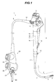
- FIG. 1 is an entire view of an endoscope
- FIG. 2 is a perspective view of a distal end portion as viewed from oblique above
- FIG. 3 is a front view of the distal end potion
- FIG. 4 is a cross sectional view along IV-IV in FIG. 2
- FIG. 5 is a cross sectional view along V-V in FIG. 4
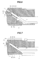
- FIG. 6 is a cross sectional view along VI-VI in FIG. 4
- FIG. 7 is a cross sectional view along VII-VII in FIG. 4
- FIG. 8 is a perspective view of a holding frame that holds a light guide and an image guide
- FIG. 9 is an exploded perspective view of the light guide, the image guide and the holding frame
- FIGS. 10 and 11 are explanatory views when the light guide and the image guide are removed from a distal end rigid portion.
- An endoscope shown in FIG. 1 is an endoscope for bronchia (a bronchoscope).
- An enlarged view of a distal end portion 5 in FIG. 1 is shown in FIG. 2 , and in the present embodiment, more specifically, the endoscope is an ultrasound bronchoscope which is provided with an ultrasound observation portion 8 for obtaining an ultrasound image and an optical observation section 9 for obtaining an optical image.
- the endoscope 1 is configured to include an insertion portion 2 which is elongated and capable of being inserted into an observation target region such as bronchia in a subject, an operation portion 3 provided continuously to a proximal end side of the insertion portion 2, and an universal cord 4 extended from a side portion of the operation portion 3.
- the insertion portion 2 is configured with the distal end portion 5, a bending portion 6 and a flexible portion 7 that are connected sequentially from a distal end, the bending portion 6 being bendable and disposed on a proximal end side of the distal end portion 5, the flexible portion 7 being elongated, having flexibility and disposed on a proximal end side of the bending portion 6.
- the operation portion 3 includes an operation portion body 10 forming an operation grasping portion, and a distal end side of the operation portion body 10 is connected to a proximal end side of the flexible portion 7 through a bending proof portion 11. Further, at locations close to a distal end of the operation portion body 10, an air/water feeding port 12, as an opening portion of an air/water feeding channel (not shown) which is a conduit inside the insertion portion 2, is provided, and a treatment instrument insertion port 13, as an opening portion on a proximal end side of a treatment instrument insertion channel (not shown) which is a conduit for insertion of a treatment instrument into the insertion portion 2, is provided.
- an angle lever 14 for bending operation of the bending portion 6 is provided, and switches 15 for various endoscope functions are provided. Further, inside the operation portion 3, a proximal end side of an image guide 16 is placed, and further a solid-state image pickup device 18 such as a CCD for forming an optical image transmitted from the image guide through a relay lens system 17 is provided.
- One end side of the universal cord 4 is provided continuously to a side portion of the operation portion body 10 through a bending proof portion 19.
- a scope connector portion 20 is provided at an extended end which is the other end side of the universal cord 4.
- a light source side connector 21 which is attachable to and detachable from a light source apparatus not shown.
- a proximal end portion of a light guide 22 that extends from a side of the insertion portion 2 is provided to protrude, and electric contact points 23 are disposed, and when the light source side connector 21 is connected to the light source apparatus, the light guide 22 is optically connected to a light source in the light source apparatus and the electric contact points 23 are electrically connected to a power supply in the light source apparatus.
- an ultrasound connector 24 which is attachable to and detachable from a ultrasound observation apparatus not shown
- an electric connector 25 which is attachable to and detachable from a video processor not shown.
- the distal end portion 5 includes a distal end rigid portion 31 having a proximal end side continuously connected to the bending portion 6.
- the distal end rigid portion 31 is formed of hard resin or the like, for example.
- a channel communication hole 35 is provided by boring inside the distal end rigid portion 31, and at a proximal end side of the channel communication hole 35, a connecting fitting 36 for connection with a distal end side of the treatment instrument insertion channel is fitted (see FIG. 5 ).
- a distal end side of the channel communication hole 35 is opened on a circumferential surface of the distal end rigid portion 31, and this opening portion is set as a suction/forceps port 35a.
- a housing retaining hole 38 for retaining a housing 32 of the ultrasound observation portion 8 is provided (see FIGS. 4 and 5 ).
- the housing retaining hole 38 is formed by a hole portion that extends, for example, in an insertion axis Oi direction of the insertion portion 2.
- a pin hole 39 is provided by boring, and the pin hole 39 communicates with the housing retaining hole 38 in the distal end rigid portion 31.
- a pipe portion 32a protruding from a proximal end side of the housing 32 is inserted into the housing retaining hole 38, and the pipe portion 32a is engaged with a fixing pin 39a which is inserted into the pin hole 39 and thereby the housing 32 is retained with respect to the distal end rigid portion 31.
- an ultrasound transducer 40 of a convex type for example, is housed in the housing 32, and thereby the ultrasound observation portion 8 is configured at the distal end portion 5.
- an inclined surface 37a which is inclined at a predetermined angle with respect to the insertion axis Oi.
- an objective lens 41 and an illumination lens 42 constituting an optical observation portion 9 are disposed on the inclined surface 37a of the distal end face 37.
- the objective lens 41 and the illumination lens 42 are held in the distal end rigid portion 31 with the image guide 16 and the light guide 22, through a holding frame 46.
- a holding hole 45 with a distal end side that opens on the inclined surface 37a is provided in the distal end rigid portion 31, and the holding frame 46 is fixed in the holding hole 45.
- the holding frame 46 is formed by a member that is made of metal in a shape of an approximately elliptic cylinder, and bears a greater shear stress than the distal end rigid portion 31, as shown in FIGS. 4 and 8 , for example.
- a first through hole 47 and a second through hole 48 that extend in the insertion axis Oi direction (more specifically, in a direction inclined by a predetermined angle with respect to the insertion axis Oi) are provided by boring, and further on a side surface (an outer circumferential surface) of the holding frame 46, a pair of grooves 49 extending along axial directions of the through holes 47 and 48 are provided by cutting.
- an inter-hole distance d of the first and second through holes 46 and 47 is set to be as small as possible, and the distance is set to be 0.1 mm, for example.
- the grooves 49 are provided at a portion having a large thickness on the holding frame 46, and the grooves 49 in the present embodiment are arranged at portions having the largest thickness, between the first and the second through holes 47 and 48.
- a mouthpiece 50 which holds objective lenses 41 and a distal end side of the image guide 16 to be united is inserted into the first through hole 47, and is fixed to the first through hole 47 with an adhesive or the like. Further, the illumination lens 42 and a distal end side of the light guide 22 are inserted into the second through hole, and are fixed to the second through hole 47 with an adhesive of the like.
- the holding frame 46 which holds the image guide 16 and the light guide 22 with the objective lenses 41 and the illumination lens 42 integrally, is inserted into the holding hole 45 and fixed to the hole with an adhesive of the like.
- the holding frame 46 is fixed in a state of being positioned such that one end face of the holding frame is flush with the inclined surface 37a (see FIGS. 6 and 7 ), and one of the pair of grooves 49 is close to a peripheral portion of the distal end face 37 (the inclined surface 37a) (see FIGS. 3 and 4 ).
- respective one ends of the grooves 49 are exposed on the inclined surface 37a, and one of the grooves 49 is arranged in the vicinity of the circumferential surface of the distal end rigid portion 31.
- the holding frame 46 made of material that bears the greater shear stress than that of the distal end rigid portion 31 (the distal end portion 5) is adhered and fixed to the distal end rigid portion 31 in a state where the one end face is exposed from the inclined surface 37a, and the image guide 16 and light guide 22 are held through the holding frame 46, and thereby downsizing of the distal end portion 5 can be realized without lowering durability.
- the first and second through holes 47 and 48 for holding the image guide 16 and the light guide 22 are provided in the holding frame 46 which is formed by the material that bears the greater shear stress than that of the distal end rigid portion 31, and thereby the inter-hole distance d can be set to be small while maintaining durability in comparison with a case where these through holes 47 and 48 are provided in the distal end rigid portion 31, and consequently it is possible to facilitate downsizing of the distal end rigid portion 31 (the distal end portion 5).
- the grooves 49 are provided on the side surface of the holding frame 46 that bears the greater shear stress than the distal end rigid portion 31, and the one ends of the grooves 49 are exposed on the distal end face 37 (the inclined surface 37a) of the distal end rigid portion 31, and thereby in making repairs, for example, in a case where a part other than the optical observation section 9 is failed, the image guide 16 and the light guide 22 can be easily removed from the distal end rigid portion 31 and reused without breaking these components, so that repairability can be improved. That is, as shown in FIGS.
- a blade 51 of a cutter or the like is brought into contact with the distal end rigid portion 31 using one end of the groove 49 exposed from the inclined surface 37a as a mark, and the distal end rigid portion 31 is incised along the groove 49, and thereby the optical observation section 9 which is reusable can be easily removed from the distal end rigid portion 31.
- a fitting groove (a first fitting groove 55) is provided on the holding frame 46, and one of the image guide 16 and the light guide 22 with associated elements (e.g. the image guide 16 with associated elements) can be held in the fitting groove 55.
- the grooves 49 can be provided on the holding frame 46 without increasing size of the holding frame 46 by arranging the grooves 49 between the fitting groove and the through hole (e.g. between the first fitting groove 55 and the second through hole 48).
- first and second fitting grooves 55 and 56 are provided on the holding frame, instead of the first and second through holes, and the image guide 16 and the light guide 22 are fixed to the fitting grooves 55 and 56, respectively, through the mouthpieces 50.
- the grooves 49 can be provided on the holding frame 46 without increasing size of the holding frame 46 by arranging the grooves 49 between the first and second fitting grooves 55 and 56.
- a holding frame 60 in a shape of an approximately prism can be adopted, as shown in FIGS. 15 and 16 .
- a space for forming the groove 49 can be secured appropriately at one of four corners of the holding frame 60, as well at a location between the through holes 47 and 48. Further, in these four corners, at regions close to the peripheral portion of the distal end face 37 (the inclined surface 37a), the grooves 49 can be provided.
- the blade 51 of the cutter or the like is brought into contact with the distal end rigid portion 31 at two places using each one end of the grooves 49 as a mark, and the distal end rigid portion 31 is incised along the grooves 49, and thereby the optical observation section 9 can be more easily removed from the distal end rigid portion 31.
- the example shown in the figures concerns a case where the grooves 49 are provided at two places, but it is a matter of course that the grooves may be provided at two places or more, for example, by further providing a groove between the first and second through holes 47 and 48.
- the present invention is not limited to the foregoing embodiments and various modifications and changes are possible, and those modifications and changes are within a technical scope of the present invention.
- the configurations of the foregoing embodiments or modified examples may be appropriately combined.
- the present invention can be applied to a rigid endoscope which does not include a bending portion and has a rigid insertion portion.
- the present invention is not limited to this and is applicable to an endoscope or the like for a digestive organ, a circulatory organ, brain surgery, a urinary organ, a genital organ, for example.
Landscapes
- Health & Medical Sciences (AREA)
- Life Sciences & Earth Sciences (AREA)
- Physics & Mathematics (AREA)
- Surgery (AREA)
- Optics & Photonics (AREA)
- Engineering & Computer Science (AREA)
- Medical Informatics (AREA)
- Veterinary Medicine (AREA)
- Pathology (AREA)
- Nuclear Medicine, Radiotherapy & Molecular Imaging (AREA)
- Biomedical Technology (AREA)
- Heart & Thoracic Surgery (AREA)
- Biophysics (AREA)
- Molecular Biology (AREA)
- Animal Behavior & Ethology (AREA)
- General Health & Medical Sciences (AREA)
- Public Health (AREA)
- Radiology & Medical Imaging (AREA)
- Pulmonology (AREA)
- Astronomy & Astrophysics (AREA)
- General Physics & Mathematics (AREA)
- Otolaryngology (AREA)
- Physiology (AREA)
- Manufacturing & Machinery (AREA)
- Endoscopes (AREA)
- Ultra Sonic Daignosis Equipment (AREA)
- Instruments For Viewing The Inside Of Hollow Bodies (AREA)
Abstract
Description
- The present invention relates to an endoscope having a distal end portion in which distal end sides of a light guide and an image guide are held.
- In conventional endoscopes, there is known one which forms an optical image inside a body on a solid-state image pickup device such as a CCD, and displays the image on a monitor, etc. Further, in this type of endoscope, in order to reduce a diameter of a distal end portion of an insertion portion, there is known an endoscope in which the solid-state image pickup device is arranged in an operation portion and an optical image formed by an objective optical system arranged in the distal end portion is conducted to the operation portion through an image guide, and the optical image formed at an emission end of the image guide is produced on the solid-state image pickup device in the operation portion through a relay lens system.
- Here, it is general that this type of endoscope has a light guide for transmitting illumination light to the distal end portion in addition to the image guide, and distal end sides of the image guide and the light guide are held by being individually inserted into through holes provided to be close to each other at a distal end rigid portion (see for example Japanese Patent Laid-Open Publication No.
2009-28109 - Incidentally, in an ultrasound endoscope provided with an ultrasound observation section at a distal end portion in addition to an optical observation portion as described above, it is general that a distal end rigid portion made of resin is adopted for the purpose of securing high insulation property.
- Generally, since the image guide and the light guide are adhered and fixed to the through holes of the distal end rigid portion, when the distal end rigid portion is to be repaired, it is difficult to reuse the image guide and the light guide after the repair even though these elements have no problem.
- The present invention has been made in view of the above circumstances and an object of the present invention is to provide an endoscope capable of improving repairability.
- An endoscope according to an aspect of the present invention includes: a distal end portion to be inserted into a subject; a light guide that transmits light to the distal end portion; an image guide that transmits video information obtained at the distal end portion; a holding frame that is made of a material to bear a greater shear stress than the distal end portion, and holds distal end sides of the light guide and the image guide by being adhered and fixed in the distal end portion in a state where one end face of the holding frame is exposed from a distal end face of the distal end portion; and at least one groove that is provided on a side surface of the holding frame in an insertion direction of the light guide and the image guide, and has one end exposed on the distal end face.
-
-
FIG. 1 is an entire view of an endoscope; -
FIG. 2 is a perspective view of a distal end portion as viewed from oblique above; -
FIG. 3 is a front view of the distal end potion; -
FIG. 4 is a cross sectional view along IV-IV inFIG. 2 ; -
FIG. 5 is a cross sectional view along V-V inFIG. 4 ; -
FIG. 6 is a cross sectional view along VI-VI inFIG. 4 ; -
FIG. 7 is a cross sectional view along VII-VII inFIG. 4 ; -
FIG. 8 is a perspective view of a holding frame that holds a light guide and an image guide; -
FIG. 9 is an exploded perspective view of the holding frame that holds the light guide and the image guide; -
FIG. 10 is an explanatory view when the light guide and the image guide are removed from a distal end rigid portion; -
FIG. 11 is an explanatory view when the light guide and the image guide are removed from the distal end rigid portion; -
FIG. 12 is a perspective view showing a modified example of the holding frame that holds the light guide and the image guide; -
FIG. 13 is a perspective view showing a modified example of the holding frame; -
FIG. 14 is a perspective view showing a modified example of the holding frame; -
FIG. 15 is an explanatory view when the light guide and the image guide are removed from the distal end rigid portion; and -
FIG. 16 is an explanatory view when the light guide and the image guide are removed from the distal end rigid portion. - Hereinafter, aspects of the present invention will be described referring to the drawings. The drawings relate to an embodiment of the present invention, and
FIG. 1 is an entire view of an endoscope,FIG. 2 is a perspective view of a distal end portion as viewed from oblique above,FIG. 3 is a front view of the distal end potion,FIG. 4 is a cross sectional view along IV-IV inFIG. 2 ,FIG. 5 is a cross sectional view along V-V inFIG. 4 ,FIG. 6 is a cross sectional view along VI-VI inFIG. 4 ,FIG. 7 is a cross sectional view along VII-VII inFIG. 4 ,FIG. 8 is a perspective view of a holding frame that holds a light guide and an image guide,FIG. 9 is an exploded perspective view of the light guide, the image guide and the holding frame, andFIGS. 10 and 11 are explanatory views when the light guide and the image guide are removed from a distal end rigid portion. - An endoscope shown in
FIG. 1 is an endoscope for bronchia (a bronchoscope). An enlarged view of adistal end portion 5 inFIG. 1 is shown inFIG. 2 , and in the present embodiment, more specifically, the endoscope is an ultrasound bronchoscope which is provided with anultrasound observation portion 8 for obtaining an ultrasound image and anoptical observation section 9 for obtaining an optical image. Theendoscope 1 is configured to include aninsertion portion 2 which is elongated and capable of being inserted into an observation target region such as bronchia in a subject, anoperation portion 3 provided continuously to a proximal end side of theinsertion portion 2, and anuniversal cord 4 extended from a side portion of theoperation portion 3. - The
insertion portion 2 is configured with thedistal end portion 5, abending portion 6 and aflexible portion 7 that are connected sequentially from a distal end, thebending portion 6 being bendable and disposed on a proximal end side of thedistal end portion 5, theflexible portion 7 being elongated, having flexibility and disposed on a proximal end side of thebending portion 6. - The
operation portion 3 includes anoperation portion body 10 forming an operation grasping portion, and a distal end side of theoperation portion body 10 is connected to a proximal end side of theflexible portion 7 through abending proof portion 11. Further, at locations close to a distal end of theoperation portion body 10, an air/water feeding port 12, as an opening portion of an air/water feeding channel (not shown) which is a conduit inside theinsertion portion 2, is provided, and a treatmentinstrument insertion port 13, as an opening portion on a proximal end side of a treatment instrument insertion channel (not shown) which is a conduit for insertion of a treatment instrument into theinsertion portion 2, is provided. On the other hand, at locations close to a proximal end of theoperation portion body 10, anangle lever 14 for bending operation of thebending portion 6 is provided, andswitches 15 for various endoscope functions are provided. Further, inside theoperation portion 3, a proximal end side of animage guide 16 is placed, and further a solid-stateimage pickup device 18 such as a CCD for forming an optical image transmitted from the image guide through arelay lens system 17 is provided. - One end side of the
universal cord 4 is provided continuously to a side portion of theoperation portion body 10 through abending proof portion 19. On the other hand, at an extended end which is the other end side of theuniversal cord 4, ascope connector portion 20 is provided. At an end portion of thescope connector portion 20, there is provided a lightsource side connector 21 which is attachable to and detachable from a light source apparatus not shown. At the lightsource side connector 21, a proximal end portion of alight guide 22 that extends from a side of theinsertion portion 2 is provided to protrude, andelectric contact points 23 are disposed, and when the lightsource side connector 21 is connected to the light source apparatus, thelight guide 22 is optically connected to a light source in the light source apparatus and theelectric contact points 23 are electrically connected to a power supply in the light source apparatus. Further, at a side portion of thescope connector portion 20, there are provided anultrasound connector 24 which is attachable to and detachable from a ultrasound observation apparatus not shown, and anelectric connector 25 which is attachable to and detachable from a video processor not shown. - Next, a configuration of the
distal end portion 5 in theabove endoscope 1 will be described referring toFIGS. 2-9 . As shown inFIGS. 2 and 3 , thedistal end portion 5 includes a distal endrigid portion 31 having a proximal end side continuously connected to thebending portion 6. - The distal end
rigid portion 31 is formed of hard resin or the like, for example. Achannel communication hole 35 is provided by boring inside the distal endrigid portion 31, and at a proximal end side of thechannel communication hole 35, a connecting fitting 36 for connection with a distal end side of the treatment instrument insertion channel is fitted (seeFIG. 5 ). On the other hand, a distal end side of thechannel communication hole 35 is opened on a circumferential surface of the distal endrigid portion 31, and this opening portion is set as a suction/forceps port 35a. - Further, on a
distal end face 37 of the distal endrigid portion 31, ahousing retaining hole 38 for retaining ahousing 32 of theultrasound observation portion 8 is provided (seeFIGS. 4 and 5 ). Thehousing retaining hole 38 is formed by a hole portion that extends, for example, in an insertion axis Oi direction of theinsertion portion 2. Furthermore, on the circumferential surface of the distal endrigid portion 31, apin hole 39 is provided by boring, and thepin hole 39 communicates with thehousing retaining hole 38 in the distal endrigid portion 31. - A
pipe portion 32a protruding from a proximal end side of thehousing 32 is inserted into thehousing retaining hole 38, and thepipe portion 32a is engaged with afixing pin 39a which is inserted into thepin hole 39 and thereby thehousing 32 is retained with respect to the distal endrigid portion 31. Further, anultrasound transducer 40 of a convex type, for example, is housed in thehousing 32, and thereby theultrasound observation portion 8 is configured at thedistal end portion 5. - Further, at a region of the
distal end face 37 of the distal endrigid portion 31, which is in the vicinity of the suction/forceps port and is offset to one side with respect to the insertion axis Oi, there is formed aninclined surface 37a which is inclined at a predetermined angle with respect to the insertion axis Oi. - On the
inclined surface 37a of thedistal end face 37, anobjective lens 41 and anillumination lens 42 constituting anoptical observation portion 9 are disposed. In this embodiment, theobjective lens 41 and theillumination lens 42 are held in the distal endrigid portion 31 with theimage guide 16 and thelight guide 22, through aholding frame 46. - Specifically, as shown in
FIGS. 6 and 7 , for example, aholding hole 45 with a distal end side that opens on theinclined surface 37a is provided in the distal endrigid portion 31, and theholding frame 46 is fixed in theholding hole 45. - The
holding frame 46 is formed by a member that is made of metal in a shape of an approximately elliptic cylinder, and bears a greater shear stress than the distal endrigid portion 31, as shown inFIGS. 4 and8 , for example. Inside theholding frame 46, a first throughhole 47 and a second throughhole 48 that extend in the insertion axis Oi direction (more specifically, in a direction inclined by a predetermined angle with respect to the insertion axis Oi) are provided by boring, and further on a side surface (an outer circumferential surface) of theholding frame 46, a pair ofgrooves 49 extending along axial directions of the throughholes - Here, it is desirable that an inter-hole distance d of the first and second through
holes 46 and 47 (seeFIGS. 4 and8 ) is set to be as small as possible, and the distance is set to be 0.1 mm, for example. Further, it is desirable that thegrooves 49 are provided at a portion having a large thickness on theholding frame 46, and thegrooves 49 in the present embodiment are arranged at portions having the largest thickness, between the first and the second throughholes - As shown in
FIGS. 6-9 , amouthpiece 50 which holdsobjective lenses 41 and a distal end side of theimage guide 16 to be united is inserted into the first throughhole 47, and is fixed to the first throughhole 47 with an adhesive or the like. Further, theillumination lens 42 and a distal end side of thelight guide 22 are inserted into the second through hole, and are fixed to the second throughhole 47 with an adhesive of the like. - Further, the
holding frame 46, which holds theimage guide 16 and thelight guide 22 with theobjective lenses 41 and theillumination lens 42 integrally, is inserted into theholding hole 45 and fixed to the hole with an adhesive of the like. At that time, the holdingframe 46 is fixed in a state of being positioned such that one end face of the holding frame is flush with theinclined surface 37a (seeFIGS. 6 and 7 ), and one of the pair ofgrooves 49 is close to a peripheral portion of the distal end face 37 (theinclined surface 37a) (seeFIGS. 3 and4 ). Thereby, respective one ends of thegrooves 49 are exposed on theinclined surface 37a, and one of thegrooves 49 is arranged in the vicinity of the circumferential surface of the distal endrigid portion 31. - According to the above embodiment, the holding
frame 46 made of material that bears the greater shear stress than that of the distal end rigid portion 31 (the distal end portion 5) is adhered and fixed to the distal endrigid portion 31 in a state where the one end face is exposed from theinclined surface 37a, and theimage guide 16 andlight guide 22 are held through the holdingframe 46, and thereby downsizing of thedistal end portion 5 can be realized without lowering durability. That is, the first and second throughholes image guide 16 and thelight guide 22 are provided in the holdingframe 46 which is formed by the material that bears the greater shear stress than that of the distal endrigid portion 31, and thereby the inter-hole distance d can be set to be small while maintaining durability in comparison with a case where these throughholes rigid portion 31, and consequently it is possible to facilitate downsizing of the distal end rigid portion 31 (the distal end portion 5). - In addition, the
grooves 49 are provided on the side surface of the holdingframe 46 that bears the greater shear stress than the distal endrigid portion 31, and the one ends of thegrooves 49 are exposed on the distal end face 37 (theinclined surface 37a) of the distal endrigid portion 31, and thereby in making repairs, for example, in a case where a part other than theoptical observation section 9 is failed, theimage guide 16 and thelight guide 22 can be easily removed from the distal endrigid portion 31 and reused without breaking these components, so that repairability can be improved. That is, as shown inFIGS. 10 and 11 , for example, ablade 51 of a cutter or the like is brought into contact with the distal endrigid portion 31 using one end of thegroove 49 exposed from theinclined surface 37a as a mark, and the distal endrigid portion 31 is incised along thegroove 49, and thereby theoptical observation section 9 which is reusable can be easily removed from the distal endrigid portion 31. - Here, in the above embodiment, one example of the configuration in which only the
objective lenses 41 and theimage guide 16 are held in the holdingframe 46 through themouthpiece 50 is described, but for example, as shown inFIG. 12 , it is possible that theillumination lens 42 and thelight guide 22 are adhered and fixed to the holdingframe 46 through themouthpiece 50. Alternatively, although not shown, is it possible that theobjective lenses 41 and theimage guide 16 are directly adhered and fixed to the first throughhole 47 of the holdingframe 46 without the mouthpiece intervened. - Further, various modifications are possible with respect to the configuration of the holding
frame 46. For example, as shown inFIG. 13 , instead of one of the first and second through holes (the first through hole in the example shown inFIG. 13 ), a fitting groove (a first fitting groove 55) is provided on the holdingframe 46, and one of theimage guide 16 and thelight guide 22 with associated elements (e.g. theimage guide 16 with associated elements) can be held in thefitting groove 55. With this configuration, a holding structure of the image guide and thelight guide 22 with associated elements can be more reduced in size. In this case also, thegrooves 49 can be provided on the holdingframe 46 without increasing size of the holdingframe 46 by arranging thegrooves 49 between the fitting groove and the through hole (e.g. between the firstfitting groove 55 and the second through hole 48). - Alternatively, for example, as shown in
FIG. 14 , it is possible that first and secondfitting grooves image guide 16 and thelight guide 22 are fixed to thefitting grooves mouthpieces 50. With this configuration, a holding structure of the image guide and thelight guide 22 can be further reduced in size. In this case also, thegrooves 49 can be provided on the holdingframe 46 without increasing size of the holdingframe 46 by arranging thegrooves 49 between the first and secondfitting grooves - Further, various modifications are possible with respect to the shape of the holding
frame 46. For example, instead of the holdingframe 46 in the shape of an approximately elliptic cylinder, a holdingframe 60 in a shape of an approximately prism can be adopted, as shown inFIGS. 15 and 16 . In this case, a space for forming thegroove 49 can be secured appropriately at one of four corners of the holdingframe 60, as well at a location between the throughholes inclined surface 37a), thegrooves 49 can be provided. With this configuration, theblade 51 of the cutter or the like is brought into contact with the distal endrigid portion 31 at two places using each one end of thegrooves 49 as a mark, and the distal endrigid portion 31 is incised along thegrooves 49, and thereby theoptical observation section 9 can be more easily removed from the distal endrigid portion 31. Besides, the example shown in the figures concerns a case where thegrooves 49 are provided at two places, but it is a matter of course that the grooves may be provided at two places or more, for example, by further providing a groove between the first and second throughholes - Besides, the present invention is not limited to the foregoing embodiments and various modifications and changes are possible, and those modifications and changes are within a technical scope of the present invention. For example, it is a matter of course that the configurations of the foregoing embodiments or modified examples may be appropriately combined. Further, the present invention can be applied to a rigid endoscope which does not include a bending portion and has a rigid insertion portion.
- Further, in the foregoing embodiments, one example in which the present invention is applied to the bronchoscope which requires reduction in diameter is described, but the present invention is not limited to this and is applicable to an endoscope or the like for a digestive organ, a circulatory organ, brain surgery, a urinary organ, a genital organ, for example.
- The present application is filed claiming the priority of Japanese Patent Application No.
2013-132944
Claims (5)
- An endoscope comprising:a distal end portion to be inserted into a subject;a light guide that transmits light to the distal end portion;an image guide that transmits video information obtained at the distal end portion;a holding frame that is made of a material to bear a greater shear stress than the distal end portion, and holds distal end sides of the light guide and the image guide by being adhered and fixed in the distal end portion in a state where one end face of the holding frame is exposed from a distal end face of the distal end portion; andat least one groove that is provided on a side surface of the holding frame in an insertion direction of the light guide and the image guide, and has one end exposed on the distal end face.
- The endoscope according to claim 1, wherein the holding frame is located eccentrically on the distal end face, and two or more grooves, each identical to the groove, are provided on the side surface of the holding frame at regions close to a peripheral portion of the distal end face.
- The endoscope according to claim 1, wherein the holding frame has a first through hole to which the image guide is inserted to be held, and a second through hole to which the light guide is inserted to be held, and the groove is provided between the first through hole and the second through hole.
- The endoscope according to claim 1, wherein the holding frame has a through hole to which one of the image guide and the light guide is inserted to be held, and a fitting groove to which other of the image guide and the light guide is fitted to be held, and the groove is provided between the through hole and the fitting groove.
- The endoscope according to claim 1, wherein the holding frame has a first fitting groove to which the image guide is inserted to be held, and a second fitting groove to which the light guide is inserted to be held, and the groove is provided between the first fitting groove and the second fitting groove.
Applications Claiming Priority (2)
| Application Number | Priority Date | Filing Date | Title |
|---|---|---|---|
| JP2013132944 | 2013-06-25 | ||
| PCT/JP2014/063223 WO2014208218A1 (en) | 2013-06-25 | 2014-05-19 | Endoscope |
Publications (2)
| Publication Number | Publication Date |
|---|---|
| EP2942002A1 true EP2942002A1 (en) | 2015-11-11 |
| EP2942002A4 EP2942002A4 (en) | 2016-10-26 |
Family
ID=52141570
Family Applications (1)
| Application Number | Title | Priority Date | Filing Date |
|---|---|---|---|
| EP14817290.1A Withdrawn EP2942002A4 (en) | 2013-06-25 | 2014-05-19 | Endoscope |
Country Status (5)
| Country | Link |
|---|---|
| US (1) | US9636009B2 (en) |
| EP (1) | EP2942002A4 (en) |
| JP (1) | JP5769907B2 (en) |
| CN (1) | CN104968254B (en) |
| WO (1) | WO2014208218A1 (en) |
Families Citing this family (9)
| Publication number | Priority date | Publication date | Assignee | Title |
|---|---|---|---|---|
| JP2017225746A (en) * | 2016-06-24 | 2017-12-28 | オリンパス株式会社 | Endoscope |
| JP2019000161A (en) * | 2017-06-12 | 2019-01-10 | オリンパス株式会社 | Endoscope |
| JP6925501B2 (en) * | 2018-03-02 | 2021-08-25 | 富士フイルム株式会社 | Image processing equipment and endoscopic system |
| WO2020003474A1 (en) * | 2018-06-28 | 2020-01-02 | オリンパス株式会社 | Endoscope tip end structure and endoscope |
| JP7249788B2 (en) * | 2019-01-22 | 2023-03-31 | オリンパス株式会社 | Endoscope |
| JP7155396B2 (en) * | 2019-03-19 | 2022-10-18 | オリンパス株式会社 | Ultrasound endoscope and insertion tube |
| CN115297785B (en) | 2020-03-26 | 2025-08-26 | 富士胶片株式会社 | Ultrasound endoscope |
| WO2023148901A1 (en) * | 2022-02-03 | 2023-08-10 | オリンパスメディカルシステムズ株式会社 | Endoscope and tip body |
| US12121212B2 (en) * | 2022-02-04 | 2024-10-22 | Olympus Medical Systems Corp. | Insertion instrument, distal end portion of insertion instrument and manufacturing method of insertion instrument |
Family Cites Families (11)
| Publication number | Priority date | Publication date | Assignee | Title |
|---|---|---|---|---|
| JPS62113125A (en) * | 1985-11-13 | 1987-05-25 | Olympus Optical Co Ltd | Endoscope |
| JP3869496B2 (en) * | 1996-07-16 | 2007-01-17 | オリンパス株式会社 | Endoscope device |
| JP2000300567A (en) * | 1999-04-20 | 2000-10-31 | Olympus Optical Co Ltd | Ultrasonic endoscope |
| JP3691700B2 (en) * | 1999-10-18 | 2005-09-07 | オリンパス株式会社 | Ultrasound endoscope |
| JP3894092B2 (en) * | 2002-10-18 | 2007-03-14 | フジノン株式会社 | Ultrasound endoscope |
| US7699773B2 (en) * | 2003-03-06 | 2010-04-20 | Precision Optics Corporation | Repairable endoscope |
| US7922654B2 (en) * | 2004-08-09 | 2011-04-12 | Boston Scientific Scimed, Inc. | Fiber optic imaging catheter |
| JP4402538B2 (en) * | 2004-07-26 | 2010-01-20 | オリンパス株式会社 | Endoscope, manufacturing method and repair method |
| JP4869645B2 (en) * | 2005-07-04 | 2012-02-08 | オリンパス株式会社 | Endoscope |
| JP2009028109A (en) | 2007-07-25 | 2009-02-12 | Olympus Medical Systems Corp | Ultrasound endoscope |
| US8427533B2 (en) * | 2007-12-19 | 2013-04-23 | Olympus Medical Systems Corp. | Image pickup apparatus, electronic endoscope, and lens unit |
-
2014
- 2014-05-19 WO PCT/JP2014/063223 patent/WO2014208218A1/en not_active Ceased
- 2014-05-19 CN CN201480007597.0A patent/CN104968254B/en active Active
- 2014-05-19 JP JP2015516135A patent/JP5769907B2/en active Active
- 2014-05-19 EP EP14817290.1A patent/EP2942002A4/en not_active Withdrawn
-
2015
- 2015-03-31 US US14/673,964 patent/US9636009B2/en active Active
Also Published As
| Publication number | Publication date |
|---|---|
| EP2942002A4 (en) | 2016-10-26 |
| CN104968254A (en) | 2015-10-07 |
| JPWO2014208218A1 (en) | 2017-02-23 |
| JP5769907B2 (en) | 2015-08-26 |
| CN104968254B (en) | 2018-05-04 |
| WO2014208218A1 (en) | 2014-12-31 |
| US9636009B2 (en) | 2017-05-02 |
| US20150265142A1 (en) | 2015-09-24 |
Similar Documents
| Publication | Publication Date | Title |
|---|---|---|
| US9636009B2 (en) | Endoscope | |
| JP3894092B2 (en) | Ultrasound endoscope | |
| JP4916595B2 (en) | Imaging unit | |
| EP2837324B1 (en) | Endoscope | |
| CN103037750B (en) | Endoscope | |
| US11925313B2 (en) | Endoscope and endoscope system | |
| JP4618410B2 (en) | Ultrasound endoscope | |
| CN107788935B (en) | Endoscope and method for assembling endoscope | |
| US20170209030A1 (en) | Endoscope | |
| EP2721991B1 (en) | Endoscope | |
| US9782149B2 (en) | Endoscope | |
| WO2020166070A1 (en) | Endoscope, grounding method and method for grounding tip end section of endoscope | |
| JP2013150700A (en) | Endoscope | |
| JP2013128710A (en) | Component fixing structure of endoscope | |
| US11076744B2 (en) | Method of manufacturing endoscope and endoscope | |
| JP5160020B2 (en) | Endoscope device | |
| JP2018171257A (en) | Ultrasound endoscope and hood for ultrasound endoscope | |
| EP3006986A1 (en) | Endoscope | |
| JP2005131128A (en) | Ultrasonic endoscope |
Legal Events
| Date | Code | Title | Description |
|---|---|---|---|
| PUAI | Public reference made under article 153(3) epc to a published international application that has entered the european phase |
Free format text: ORIGINAL CODE: 0009012 |
|
| 17P | Request for examination filed |
Effective date: 20150723 |
|
| AK | Designated contracting states |
Kind code of ref document: A1 Designated state(s): AL AT BE BG CH CY CZ DE DK EE ES FI FR GB GR HR HU IE IS IT LI LT LU LV MC MK MT NL NO PL PT RO RS SE SI SK SM TR |
|
| AX | Request for extension of the european patent |
Extension state: BA ME |
|
| DAX | Request for extension of the european patent (deleted) | ||
| RAP1 | Party data changed (applicant data changed or rights of an application transferred) |
Owner name: OLYMPUS CORPORATION |
|
| RAP1 | Party data changed (applicant data changed or rights of an application transferred) |
Owner name: OLYMPUS CORPORATION |
|
| A4 | Supplementary search report drawn up and despatched |
Effective date: 20160928 |
|
| RIC1 | Information provided on ipc code assigned before grant |
Ipc: A61B 1/00 20060101AFI20160922BHEP Ipc: A61B 1/06 20060101ALI20160922BHEP Ipc: A61B 1/267 20060101ALI20160922BHEP Ipc: A61B 1/04 20060101ALI20160922BHEP Ipc: G02B 23/24 20060101ALI20160922BHEP |
|
| RIN1 | Information on inventor provided before grant (corrected) |
Inventor name: OGAWA, TOMOAKI |
|
| STAA | Information on the status of an ep patent application or granted ep patent |
Free format text: STATUS: EXAMINATION IS IN PROGRESS |
|
| 17Q | First examination report despatched |
Effective date: 20190716 |
|
| STAA | Information on the status of an ep patent application or granted ep patent |
Free format text: STATUS: THE APPLICATION IS DEEMED TO BE WITHDRAWN |
|
| 18D | Application deemed to be withdrawn |
Effective date: 20191127 |