EP2941996B1 - Bodenreinigungsmaschine - Google Patents
Bodenreinigungsmaschine Download PDFInfo
- Publication number
- EP2941996B1 EP2941996B1 EP15165706.1A EP15165706A EP2941996B1 EP 2941996 B1 EP2941996 B1 EP 2941996B1 EP 15165706 A EP15165706 A EP 15165706A EP 2941996 B1 EP2941996 B1 EP 2941996B1
- Authority
- EP
- European Patent Office
- Prior art keywords
- brush
- squeegee
- supporting structure
- respect
- floor
- Prior art date
- Legal status (The legal status is an assumption and is not a legal conclusion. Google has not performed a legal analysis and makes no representation as to the accuracy of the status listed.)
- Not-in-force
Links
- 238000004140 cleaning Methods 0.000 title claims description 10
- 230000010355 oscillation Effects 0.000 claims description 9
- 239000007788 liquid Substances 0.000 description 8
- 238000005406 washing Methods 0.000 description 8
- 239000000463 material Substances 0.000 description 2
- 241000761557 Lamina Species 0.000 description 1
- 230000004913 activation Effects 0.000 description 1
- 230000000670 limiting effect Effects 0.000 description 1
- 230000014759 maintenance of location Effects 0.000 description 1
- 238000012986 modification Methods 0.000 description 1
- 230000004048 modification Effects 0.000 description 1
- 230000000284 resting effect Effects 0.000 description 1
Images


Classifications
-
- A—HUMAN NECESSITIES
- A47—FURNITURE; DOMESTIC ARTICLES OR APPLIANCES; COFFEE MILLS; SPICE MILLS; SUCTION CLEANERS IN GENERAL
- A47L—DOMESTIC WASHING OR CLEANING; SUCTION CLEANERS IN GENERAL
- A47L11/00—Machines for cleaning floors, carpets, furniture, walls, or wall coverings
- A47L11/29—Floor-scrubbing machines characterised by means for taking-up dirty liquid
- A47L11/292—Floor-scrubbing machines characterised by means for taking-up dirty liquid having rotary tools
- A47L11/293—Floor-scrubbing machines characterised by means for taking-up dirty liquid having rotary tools the tools being disc brushes
-
- A—HUMAN NECESSITIES
- A47—FURNITURE; DOMESTIC ARTICLES OR APPLIANCES; COFFEE MILLS; SPICE MILLS; SUCTION CLEANERS IN GENERAL
- A47L—DOMESTIC WASHING OR CLEANING; SUCTION CLEANERS IN GENERAL
- A47L11/00—Machines for cleaning floors, carpets, furniture, walls, or wall coverings
- A47L11/29—Floor-scrubbing machines characterised by means for taking-up dirty liquid
- A47L11/30—Floor-scrubbing machines characterised by means for taking-up dirty liquid by suction
- A47L11/302—Floor-scrubbing machines characterised by means for taking-up dirty liquid by suction having rotary tools
- A47L11/305—Floor-scrubbing machines characterised by means for taking-up dirty liquid by suction having rotary tools the tools being disc brushes
-
- A—HUMAN NECESSITIES
- A47—FURNITURE; DOMESTIC ARTICLES OR APPLIANCES; COFFEE MILLS; SPICE MILLS; SUCTION CLEANERS IN GENERAL
- A47L—DOMESTIC WASHING OR CLEANING; SUCTION CLEANERS IN GENERAL
- A47L11/00—Machines for cleaning floors, carpets, furniture, walls, or wall coverings
- A47L11/40—Parts or details of machines not provided for in groups A47L11/02 - A47L11/38, or not restricted to one of these groups, e.g. handles, arrangements of switches, skirts, buffers, levers
- A47L11/4036—Parts or details of the surface treating tools
- A47L11/4044—Vacuuming or pick-up tools; Squeegees
-
- A—HUMAN NECESSITIES
- A47—FURNITURE; DOMESTIC ARTICLES OR APPLIANCES; COFFEE MILLS; SPICE MILLS; SUCTION CLEANERS IN GENERAL
- A47L—DOMESTIC WASHING OR CLEANING; SUCTION CLEANERS IN GENERAL
- A47L11/00—Machines for cleaning floors, carpets, furniture, walls, or wall coverings
- A47L11/40—Parts or details of machines not provided for in groups A47L11/02 - A47L11/38, or not restricted to one of these groups, e.g. handles, arrangements of switches, skirts, buffers, levers
- A47L11/4052—Movement of the tools or the like perpendicular to the cleaning surface
- A47L11/4055—Movement of the tools or the like perpendicular to the cleaning surface for lifting the tools to a non-working position
-
- A—HUMAN NECESSITIES
- A47—FURNITURE; DOMESTIC ARTICLES OR APPLIANCES; COFFEE MILLS; SPICE MILLS; SUCTION CLEANERS IN GENERAL
- A47L—DOMESTIC WASHING OR CLEANING; SUCTION CLEANERS IN GENERAL
- A47L11/00—Machines for cleaning floors, carpets, furniture, walls, or wall coverings
- A47L11/40—Parts or details of machines not provided for in groups A47L11/02 - A47L11/38, or not restricted to one of these groups, e.g. handles, arrangements of switches, skirts, buffers, levers
- A47L11/4075—Handles; levers
Definitions
- the present invention relates to a floor cleaning machine.
- Floor cleaning machines which are equipped with a brush that rotates about a vertical axis and are provided with at least one nozzle for dispensing a washing liquid.
- these machines have a squeegee, which is arranged in a rear position with respect to the brush along the forward travel direction of the machine and slides in contact with the floor, allowing to collect the washing liquid and the dirt removed by the action of the brush so that they can be picked up by an intake, associated with the machine, so as to leave the floor dry and clean during the forward travel of the machine.
- This type of machine suffers the drawback that when it is moved backward, i.e., in the opposite direction with respect to their normal forward travel direction, they leave the floor wet, since the squeegee is unable, in this situation, to collect the washing liquid released by the dispensing nozzle.
- the aim of the present invention is to solve this drawback, by providing a floor cleaning machine that allows the squeegee to collect the washing liquid and dirt even when the machine is moved in the opposite direction with respect to its forward travel direction.
- an object of the invention is to provide a floor cleaning machine that can be practical to use for the user.
- Another object of the present invention is to provide a floor cleaning machine that has an extremely simple structure.
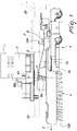
- a floor cleaning machine designated generally by the reference numeral 1, comprises a supporting structure 2, which has, along a forward travel direction 3 of the machine, a front part 2a and a rear part 2b.
- the supporting structure 2 on its side directed toward the floor 100, supports a brush 4, which can be actuated by motor means 5 with a rotary motion about a rotation axis 4a that is arranged, during use, substantially vertically.
- the brush 4 can, for example, be constituted by a disk 6a that can be coupled detachably to the actuation shaft of the motor means 5.
- Bristles 6b are anchored to the disk 6a and are intended to act by friction on the floor 100.
- one or more nozzles for dispensing a washing liquid can be associated with the supporting structure 2.
- a squeegee 7 is further associated with the supporting structure 2 and is located in the rear position with respect to the brush 4 along the forward travel direction 3 of the machine.
- the squeegee 7 is formed as usual by an arc-like supporting body 7a, which is extended around a portion of the brush 4 and to which one or more flexible laminas 7b, intended to slide on the floor 100, are coupled.
- the squeegee 7 is mounted so that it can rotate about an oscillation axis that is substantially parallel to or, more preferably, substantially coincides with the rotation axis 4a of the brush 4.
- connection means 8 which can be activated on command and are adapted to integrally associate the squeegee 7 with the brush 4, so that the squeegee 7 can be turned by the brush about its oscillation axis, so as to move the squeegee 7 from the position behind the brush 4, along the forward travel direction 3 of the machine, to a diametrically opposite position, in which it is arranged in practice in front of said brush, again along the forward travel direction 3 of the machine.
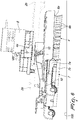
- connection means 8 can be activated by tilting the supporting structure 2, lifting its front part 2a from the floor 100, with respect to its rear part 2b, as shown in particular in Figure 8 .
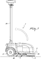
- this tilt of the supporting structure 2 can be achieved by the user by using as a lever an elongated handle 20, which rises upward from the rear part 2b of the supporting structure and by pivoting on wheels 21, conveniently associated with the rear part 2b of the supporting structure 2, in a position that lies behind the assembly constituted by the brush 4 and by the squeegee 7.
- the user by pushing downward on the grip end 20a of the handle 20, can rotate the supporting structure 2 around the region of contact with the floor 100 of its rear part, constituted by the wheels 21, so as to raise from the floor its front part 2a with respect to its rear part 2b, as shown by way of example in Figure 3 and in Figure 8 .
- stop means are also provided which are adapted to stop the rotation performed by the squeegee 7 integrally with the brush 4 when the squeegee 7 is located at the front position, preventing it from continuing beyond in rotation.
- the stop means can be constituted by a resting surface, which is formed in the front part 2b of the supporting structure 2 and is intended to be engaged by abutment by a portion of the squeegee 7.
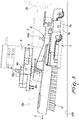
- the squeegee 7 conveniently is connected to an end of a supporting arm 9, which is pivoted, at its other end, to the supporting structure 2 about the oscillation axis of the squeegee 7.
- connection means 8 comprise a friction body 10, which is supported by the supporting arm 9 and is adapted to make contact with the brush 4, following the activation of the connection means 8, so as to integrally couple the supporting arm 9 and therefore the squeegee 7 with respect to the brush.
- the supporting arm 9 can rotate with respect to the supporting structure 2 also about an articulation axis 9a that is substantially perpendicular to said oscillation axis of the squeegee 7, in order to allow the friction body 10 to pass from an inactive condition, shown in particular in Figure 2 , in which it is disengaged from the brush 4, when the supporting structure 2 is in a position that is not inclined with respect to the floor, to an active condition, in which the friction body 10 is supported in contact with friction against the brush 4 when the supporting structure 2 is moved to an inclined condition with lifting of its front part 2a from the floor 100 with respect to its rear part 2b and vice versa.
- the friction body 10 is arranged so as to face the upper face of the disk 6a of the brush 4, so as to be able to make contact with it when it is in its active condition.
- the friction body 10 can be made of elastically yielding material, such as for example rubber or the like, and for example can be fixed to the supporting arm 9 by means of a threaded portion 10a, which is integral therewith and can be engaged by a locking nut 10b.
- the motor means 5 of the brush 4 are activated so that it can move with a rotary motion about its own rotation axis 4a.
- the brush 4 acts progressively on the various regions of the floor 100, removing the dirt that is present with the aid of the washing liquid emitted by the dispensing nozzles, and the squeegee 7 collects the washing liquid and the removed dirt.
- the supporting structure is in a condition that is not inclined with respect to the floor 100 and the friction body 10 is spaced from the brush 4 and accordingly the squeegee 7 is uncoupled with respect to the rotation of the brush 4.
- the user wishes to move the supporting structure 2 in the opposite direction with respect to the forward travel direction 3, he/she first of all tilts the supporting structure 2 so as to raise its front part 2a from the floor 100 with respect to the rear part 2b, pivoting on the wheels, as shown in Figure 8 .
- the brush 4 and the squeegee 7 rise from the floor 100 and, by losing contact with the floor 100, rotate, due to its own weight, the supporting arm 9 about the articulation axis 9a, with consequent approach of the friction body 10 to the disk 6a of the brush 4 until the friction body 10 makes contact with the disc 6a of the brush 4.
- the squeegee 7 is turned by the brush 4 about its own oscillation axis, thus moving from the position behind the brush to the position in front of said brush, remaining in this position thanks to its retention caused by the stop means.
- the user can return the supporting structure 2 to a non-tilted condition, lowering again the front part 2a of the supporting structure 2 and then, as shown in Figure 9 , can move the machine in the opposite direction with respect to the forward travel direction 3, the squeegee 7 being always able to operate in a position that lies behind the brush 4.
- the invention is capable of achieving fully the intended aim, since it allows to clean the floor both by making the machine travel in its normal forward travel direction and by moving it in the opposite direction.
- the materials used may be any according to requirements.
Landscapes
- Nozzles For Electric Vacuum Cleaners (AREA)
- Brushes (AREA)
- Cleaning In General (AREA)
Claims (6)
- Eine Bodenreinigungsmaschine, die eine tragende Struktur (2) umfasst, welche entlang einer Vorwärtsbewegungsrichtung (3) der Maschine einen vorderen Teil (2a) und einen hinteren Teil (2b) hat, wobei die tragende Struktur (2) eine Bürste (4) trägt, die drehbar um eine Drehachse (4a) angetrieben werden kann, welche im Gebrauch im Wesentlichen vertikal angeordnet ist, und eine Rakel (7), die sich im Verhältnis zu der Bürste (4) entlang der Vorwärtsbewegungsrichtung (3) der Maschine in einer hinteren Position befindet, dadurch gekennzeichnet, dass die Rakel (7) drehbar um eine Schwenkachse montiert ist, die im Wesentlichen parallel zu der Drehachse (4a) der Bürste (4) ist, wobei Verbindungsmittel (8) bereitgestellt sind, die auf Befehl aktiviert werden können und ausgebildet sind, um die Rakel (7) in der Drehung um die Drehachse (4a) starr mit der Bürste (4) zu koppeln, um die Rakel (7) im Verhältnis zu der Bürste (4) entlang der Vorwärtsbewegungsrichtung (3) der Maschine aus der hinteren Position in eine vordere Position zu bewegen.
- Die Maschine gemäß Anspruch 1, dadurch gekennzeichnet, dass die Verbindungsmittel (8) mit Hilfe einer Neigung der tragenden Struktur (2) aktiviert werden können, unter Anhebung des vorderen Teils (2a) vom Boden im Verhältnis zu dem hinteren Teil (2b).
- Die Maschine gemäß einem oder mehreren der obigen Ansprüche, dadurch gekennzeichnet, dass sie Anschlagmittel umfasst, die ausgebildet sind, um die integrale Drehung der Rakel (7) mit der Bürste (4) in die vordere Position anzuhalten.
- Die Maschine gemäß einem oder mehreren der obigen Ansprüche, dadurch gekennzeichnet, dass die Rakel (7) mit einem Ende eines Tragarms (9) verbunden ist, der an seinem anderen Ende drehgelenkig um die Schwenkachse mit der tragenden Struktur (2) verbunden ist.
- Die Maschine gemäß einem oder mehreren der obigen Ansprüche, dadurch gekennzeichnet, dass die Verbindungsmittel (8) einen Reibungskörper (10) umfassen, der von dem Tragarm (9) getragen wird und ausgebildet ist, um in Kontakt mit der Bürste (4) zu stehen, um den Tragarm (9) integral mit der Bürste (4) zu machen.
- Die Maschine gemäß einem oder mehreren der obigen Ansprüche, dadurch gekennzeichnet, dass der Tragarm (9) sich im Verhältnis zu der tragenden Struktur (2) um eine Gelenkachse (9a) drehen kann, die im Wesentlichen senkrecht zu der Schwenkachse ist, um es dem Reibungskörper (10) zu ermöglichen, aus einem inaktiven Zustand, in dem er von der Bürste (4) getrennt ist, wobei sich die tragende Struktur (2) in einem nicht gekippten Zustand befindet, in einen aktiven Zustand zu wechseln, in dem der Reibungskörper (10) mit Reibung in Kontakt mit der Bürste (4) steht, wobei sich die tragende Struktur (2) im gekippten Zustand befindet, mit Anheben des vorderen Teils (2a) vom Boden im Verhältnis zu dem hinteren Teil (2b), und umgekehrt.
Applications Claiming Priority (1)
| Application Number | Priority Date | Filing Date | Title |
|---|---|---|---|
| ITVR20140120 | 2014-05-05 |
Publications (2)
| Publication Number | Publication Date |
|---|---|
| EP2941996A1 EP2941996A1 (de) | 2015-11-11 |
| EP2941996B1 true EP2941996B1 (de) | 2017-03-15 |
Family
ID=51136683
Family Applications (1)
| Application Number | Title | Priority Date | Filing Date |
|---|---|---|---|
| EP15165706.1A Not-in-force EP2941996B1 (de) | 2014-05-05 | 2015-04-29 | Bodenreinigungsmaschine |
Country Status (5)
| Country | Link |
|---|---|
| US (1) | US20150313437A1 (de) |
| EP (1) | EP2941996B1 (de) |
| CN (1) | CN105078372A (de) |
| DK (1) | DK2941996T3 (de) |
| ES (1) | ES2628604T3 (de) |
Families Citing this family (5)
| Publication number | Priority date | Publication date | Assignee | Title |
|---|---|---|---|---|
| CN108685531B (zh) * | 2017-04-11 | 2024-03-22 | 金日清洁设备(苏州)有限公司 | 洗地机 |
| CN109758051B (zh) * | 2019-03-27 | 2024-03-19 | 南京特沃斯清洁设备有限公司 | 一种可多向清洗的手推式洗地机 |
| ES2990208T3 (es) * | 2019-05-21 | 2024-11-29 | Tech Systems By Moro S R L | Dispositivo de limpieza de superficies transitables |
| GB2586164A (en) | 2019-08-09 | 2021-02-10 | Numatic Int Ltd | Floor treatment machine |
| CN111376376B (zh) * | 2020-04-17 | 2025-07-15 | 张家港市永茂住宅工业有限公司 | 一种建筑用预制件生产线 |
Family Cites Families (5)
| Publication number | Priority date | Publication date | Assignee | Title |
|---|---|---|---|---|
| US2149453A (en) * | 1936-10-08 | 1939-03-07 | Reconstruction Finance Corp | Vacuum scrubber |
| US4805256A (en) * | 1987-10-02 | 1989-02-21 | Tennant Company | Scrubber squeegee pivoted concentric with brush drive |
| US4817233A (en) * | 1988-04-22 | 1989-04-04 | Tennant Company | Scrubber squeegees for scrubbing forward and backward |
| US5623743A (en) * | 1996-06-04 | 1997-04-29 | Clarke Industries, Inc. | Mobile surface scrubber solution recovery system |
| DE19713123C1 (de) * | 1997-03-27 | 1998-10-29 | Hefter Georg Maschb | Bodenbearbeitungsmaschine |
-
2015
- 2015-04-29 EP EP15165706.1A patent/EP2941996B1/de not_active Not-in-force
- 2015-04-29 ES ES15165706.1T patent/ES2628604T3/es active Active
- 2015-04-29 DK DK15165706.1T patent/DK2941996T3/en active
- 2015-05-05 US US14/704,703 patent/US20150313437A1/en not_active Abandoned
- 2015-05-05 CN CN201510224808.2A patent/CN105078372A/zh active Pending
Non-Patent Citations (1)
| Title |
|---|
| None * |
Also Published As
| Publication number | Publication date |
|---|---|
| DK2941996T3 (en) | 2017-06-26 |
| CN105078372A (zh) | 2015-11-25 |
| US20150313437A1 (en) | 2015-11-05 |
| EP2941996A1 (de) | 2015-11-11 |
| ES2628604T3 (es) | 2017-08-03 |
Similar Documents
| Publication | Publication Date | Title |
|---|---|---|
| EP2941996B1 (de) | Bodenreinigungsmaschine | |
| JP5878237B2 (ja) | 駆動可能な床洗浄機、及び床洗浄機を作動するための方法 | |
| US11071431B2 (en) | Floor cleaning apparatus and method of cleaning a floor | |
| ES2382531B1 (es) | Sistema de limpieza de suelos. | |
| EP2946713A1 (de) | Bodenschrubbmaschine | |
| CN203935144U (zh) | 地板处理设备 | |
| US20150067981A1 (en) | Upright vacuum cleaner having a support | |
| EP3207850B1 (de) | Reiniger | |
| RU2007131284A (ru) | Бытовой электроприбор для обработки поверхности | |
| US10076219B2 (en) | Scrubber machine | |
| US8479357B2 (en) | Moquette carpet cleaning machine operable in pull-back mode | |
| EP2800505B1 (de) | Kabelbetätigte aufzuganlage | |
| CN209595646U (zh) | 吸尘器的吸头以及配备有这种吸头的吸尘器 | |
| KR101640198B1 (ko) | 탑승식 바닥세척기 | |
| JP2010172597A (ja) | 床面等用清掃機のブラシ装置 | |
| CN102764103A (zh) | 用于拖把的清洁件安装架以及拖把 | |
| KR101258493B1 (ko) | 스팀청소기용 힌지 어셈블리 | |
| EP3636130B1 (de) | Oberflächenreinigungsvorrichtung mit einer schleudertrocknenden geweberolle | |
| CN209595645U (zh) | 吸尘器的吸头和吸尘器 | |
| US8966699B2 (en) | Floor washing-drying machine with automatically orienting scraping device | |
| EP3804600A1 (de) | Bodenschrubbertrockner | |
| KR102746428B1 (ko) | 바닥 청소기용 부착 장치 | |
| AU2013400414B2 (en) | Cleaning tool for a floor cleaning machine, and floor cleaning machine | |
| CN203841650U (zh) | 一种平板拖清洗桶 | |
| KR20100008820U (ko) | 브러쉬의 회전력으로 전방 추진력을 갖는 바닥청소기 |
Legal Events
| Date | Code | Title | Description |
|---|---|---|---|
| PUAI | Public reference made under article 153(3) epc to a published international application that has entered the european phase |
Free format text: ORIGINAL CODE: 0009012 |
|
| AK | Designated contracting states |
Kind code of ref document: A1 Designated state(s): AL AT BE BG CH CY CZ DE DK EE ES FI FR GB GR HR HU IE IS IT LI LT LU LV MC MK MT NL NO PL PT RO RS SE SI SK SM TR |
|
| AX | Request for extension of the european patent |
Extension state: BA ME |
|
| RBV | Designated contracting states (corrected) |
Designated state(s): AL AT BE BG CH CY CZ DE DK EE ES FI FR GB GR HR HU IE IS IT LI LT LU LV MC MK MT NL NO PL PT RO RS SE SI SK SM TR |
|
| 17P | Request for examination filed |
Effective date: 20160315 |
|
| GRAP | Despatch of communication of intention to grant a patent |
Free format text: ORIGINAL CODE: EPIDOSNIGR1 |
|
| RIC1 | Information provided on ipc code assigned before grant |
Ipc: A47L 11/293 20060101AFI20160822BHEP Ipc: A47L 11/30 20060101ALI20160822BHEP Ipc: A47L 11/40 20060101ALI20160822BHEP |
|
| INTG | Intention to grant announced |
Effective date: 20160922 |
|
| GRAS | Grant fee paid |
Free format text: ORIGINAL CODE: EPIDOSNIGR3 |
|
| GRAA | (expected) grant |
Free format text: ORIGINAL CODE: 0009210 |
|
| AK | Designated contracting states |
Kind code of ref document: B1 Designated state(s): AL AT BE BG CH CY CZ DE DK EE ES FI FR GB GR HR HU IE IS IT LI LT LU LV MC MK MT NL NO PL PT RO RS SE SI SK SM TR |
|
| REG | Reference to a national code |
Ref country code: CH Ref legal event code: EP Ref country code: GB Ref legal event code: FG4D |
|
| REG | Reference to a national code |
Ref country code: IE Ref legal event code: FG4D |
|
| REG | Reference to a national code |
Ref country code: AT Ref legal event code: REF Ref document number: 874712 Country of ref document: AT Kind code of ref document: T Effective date: 20170415 |
|
| REG | Reference to a national code |
Ref country code: DE Ref legal event code: R096 Ref document number: 602015001799 Country of ref document: DE |
|
| REG | Reference to a national code |
Ref country code: DK Ref legal event code: T3 Effective date: 20170623 |
|
| REG | Reference to a national code |
Ref country code: NL Ref legal event code: MP Effective date: 20170315 |
|
| REG | Reference to a national code |
Ref country code: LT Ref legal event code: MG4D |
|
| PG25 | Lapsed in a contracting state [announced via postgrant information from national office to epo] |
Ref country code: GR Free format text: LAPSE BECAUSE OF FAILURE TO SUBMIT A TRANSLATION OF THE DESCRIPTION OR TO PAY THE FEE WITHIN THE PRESCRIBED TIME-LIMIT Effective date: 20170616 Ref country code: HR Free format text: LAPSE BECAUSE OF FAILURE TO SUBMIT A TRANSLATION OF THE DESCRIPTION OR TO PAY THE FEE WITHIN THE PRESCRIBED TIME-LIMIT Effective date: 20170315 Ref country code: FI Free format text: LAPSE BECAUSE OF FAILURE TO SUBMIT A TRANSLATION OF THE DESCRIPTION OR TO PAY THE FEE WITHIN THE PRESCRIBED TIME-LIMIT Effective date: 20170315 Ref country code: LT Free format text: LAPSE BECAUSE OF FAILURE TO SUBMIT A TRANSLATION OF THE DESCRIPTION OR TO PAY THE FEE WITHIN THE PRESCRIBED TIME-LIMIT Effective date: 20170315 Ref country code: NO Free format text: LAPSE BECAUSE OF FAILURE TO SUBMIT A TRANSLATION OF THE DESCRIPTION OR TO PAY THE FEE WITHIN THE PRESCRIBED TIME-LIMIT Effective date: 20170615 |
|
| REG | Reference to a national code |
Ref country code: ES Ref legal event code: FG2A Ref document number: 2628604 Country of ref document: ES Kind code of ref document: T3 Effective date: 20170803 |
|
| REG | Reference to a national code |
Ref country code: AT Ref legal event code: MK05 Ref document number: 874712 Country of ref document: AT Kind code of ref document: T Effective date: 20170315 |
|
| PG25 | Lapsed in a contracting state [announced via postgrant information from national office to epo] |
Ref country code: RS Free format text: LAPSE BECAUSE OF FAILURE TO SUBMIT A TRANSLATION OF THE DESCRIPTION OR TO PAY THE FEE WITHIN THE PRESCRIBED TIME-LIMIT Effective date: 20170315 Ref country code: LV Free format text: LAPSE BECAUSE OF FAILURE TO SUBMIT A TRANSLATION OF THE DESCRIPTION OR TO PAY THE FEE WITHIN THE PRESCRIBED TIME-LIMIT Effective date: 20170315 Ref country code: BG Free format text: LAPSE BECAUSE OF FAILURE TO SUBMIT A TRANSLATION OF THE DESCRIPTION OR TO PAY THE FEE WITHIN THE PRESCRIBED TIME-LIMIT Effective date: 20170615 Ref country code: SE Free format text: LAPSE BECAUSE OF FAILURE TO SUBMIT A TRANSLATION OF THE DESCRIPTION OR TO PAY THE FEE WITHIN THE PRESCRIBED TIME-LIMIT Effective date: 20170315 |
|
| PG25 | Lapsed in a contracting state [announced via postgrant information from national office to epo] |
Ref country code: NL Free format text: LAPSE BECAUSE OF FAILURE TO SUBMIT A TRANSLATION OF THE DESCRIPTION OR TO PAY THE FEE WITHIN THE PRESCRIBED TIME-LIMIT Effective date: 20170315 |
|
| REG | Reference to a national code |
Ref country code: FR Ref legal event code: PLFP Year of fee payment: 3 |
|
| PG25 | Lapsed in a contracting state [announced via postgrant information from national office to epo] |
Ref country code: EE Free format text: LAPSE BECAUSE OF FAILURE TO SUBMIT A TRANSLATION OF THE DESCRIPTION OR TO PAY THE FEE WITHIN THE PRESCRIBED TIME-LIMIT Effective date: 20170315 Ref country code: SK Free format text: LAPSE BECAUSE OF FAILURE TO SUBMIT A TRANSLATION OF THE DESCRIPTION OR TO PAY THE FEE WITHIN THE PRESCRIBED TIME-LIMIT Effective date: 20170315 Ref country code: AT Free format text: LAPSE BECAUSE OF FAILURE TO SUBMIT A TRANSLATION OF THE DESCRIPTION OR TO PAY THE FEE WITHIN THE PRESCRIBED TIME-LIMIT Effective date: 20170315 Ref country code: RO Free format text: LAPSE BECAUSE OF FAILURE TO SUBMIT A TRANSLATION OF THE DESCRIPTION OR TO PAY THE FEE WITHIN THE PRESCRIBED TIME-LIMIT Effective date: 20170315 Ref country code: CZ Free format text: LAPSE BECAUSE OF FAILURE TO SUBMIT A TRANSLATION OF THE DESCRIPTION OR TO PAY THE FEE WITHIN THE PRESCRIBED TIME-LIMIT Effective date: 20170315 |
|
| PG25 | Lapsed in a contracting state [announced via postgrant information from national office to epo] |
Ref country code: SM Free format text: LAPSE BECAUSE OF FAILURE TO SUBMIT A TRANSLATION OF THE DESCRIPTION OR TO PAY THE FEE WITHIN THE PRESCRIBED TIME-LIMIT Effective date: 20170315 Ref country code: IS Free format text: LAPSE BECAUSE OF FAILURE TO SUBMIT A TRANSLATION OF THE DESCRIPTION OR TO PAY THE FEE WITHIN THE PRESCRIBED TIME-LIMIT Effective date: 20170715 Ref country code: PL Free format text: LAPSE BECAUSE OF FAILURE TO SUBMIT A TRANSLATION OF THE DESCRIPTION OR TO PAY THE FEE WITHIN THE PRESCRIBED TIME-LIMIT Effective date: 20170315 Ref country code: PT Free format text: LAPSE BECAUSE OF FAILURE TO SUBMIT A TRANSLATION OF THE DESCRIPTION OR TO PAY THE FEE WITHIN THE PRESCRIBED TIME-LIMIT Effective date: 20170717 |
|
| REG | Reference to a national code |
Ref country code: DE Ref legal event code: R097 Ref document number: 602015001799 Country of ref document: DE |
|
| PLBE | No opposition filed within time limit |
Free format text: ORIGINAL CODE: 0009261 |
|
| STAA | Information on the status of an ep patent application or granted ep patent |
Free format text: STATUS: NO OPPOSITION FILED WITHIN TIME LIMIT |
|
| REG | Reference to a national code |
Ref country code: IE Ref legal event code: MM4A |
|
| PG25 | Lapsed in a contracting state [announced via postgrant information from national office to epo] |
Ref country code: MC Free format text: LAPSE BECAUSE OF FAILURE TO SUBMIT A TRANSLATION OF THE DESCRIPTION OR TO PAY THE FEE WITHIN THE PRESCRIBED TIME-LIMIT Effective date: 20170315 |
|
| PGFP | Annual fee paid to national office [announced via postgrant information from national office to epo] |
Ref country code: FR Payment date: 20171011 Year of fee payment: 3 Ref country code: DE Payment date: 20171017 Year of fee payment: 3 Ref country code: DK Payment date: 20171016 Year of fee payment: 3 |
|
| 26N | No opposition filed |
Effective date: 20171218 |
|
| PG25 | Lapsed in a contracting state [announced via postgrant information from national office to epo] |
Ref country code: LU Free format text: LAPSE BECAUSE OF NON-PAYMENT OF DUE FEES Effective date: 20170429 Ref country code: SI Free format text: LAPSE BECAUSE OF FAILURE TO SUBMIT A TRANSLATION OF THE DESCRIPTION OR TO PAY THE FEE WITHIN THE PRESCRIBED TIME-LIMIT Effective date: 20170315 |
|
| PGFP | Annual fee paid to national office [announced via postgrant information from national office to epo] |
Ref country code: ES Payment date: 20171025 Year of fee payment: 3 |
|
| REG | Reference to a national code |
Ref country code: BE Ref legal event code: MM Effective date: 20170430 |
|
| PG25 | Lapsed in a contracting state [announced via postgrant information from national office to epo] |
Ref country code: IE Free format text: LAPSE BECAUSE OF NON-PAYMENT OF DUE FEES Effective date: 20170429 |
|
| PG25 | Lapsed in a contracting state [announced via postgrant information from national office to epo] |
Ref country code: BE Free format text: LAPSE BECAUSE OF NON-PAYMENT OF DUE FEES Effective date: 20170430 |
|
| PG25 | Lapsed in a contracting state [announced via postgrant information from national office to epo] |
Ref country code: MT Free format text: LAPSE BECAUSE OF NON-PAYMENT OF DUE FEES Effective date: 20170429 |
|
| REG | Reference to a national code |
Ref country code: DE Ref legal event code: R119 Ref document number: 602015001799 Country of ref document: DE |
|
| REG | Reference to a national code |
Ref country code: DK Ref legal event code: EBP Effective date: 20180430 |
|
| REG | Reference to a national code |
Ref country code: CH Ref legal event code: PL |
|
| PG25 | Lapsed in a contracting state [announced via postgrant information from national office to epo] |
Ref country code: DE Free format text: LAPSE BECAUSE OF NON-PAYMENT OF DUE FEES Effective date: 20181101 |
|
| PG25 | Lapsed in a contracting state [announced via postgrant information from national office to epo] |
Ref country code: LI Free format text: LAPSE BECAUSE OF NON-PAYMENT OF DUE FEES Effective date: 20180430 Ref country code: CH Free format text: LAPSE BECAUSE OF NON-PAYMENT OF DUE FEES Effective date: 20180430 |
|
| PG25 | Lapsed in a contracting state [announced via postgrant information from national office to epo] |
Ref country code: FR Free format text: LAPSE BECAUSE OF NON-PAYMENT OF DUE FEES Effective date: 20180430 |
|
| PG25 | Lapsed in a contracting state [announced via postgrant information from national office to epo] |
Ref country code: DK Free format text: LAPSE BECAUSE OF NON-PAYMENT OF DUE FEES Effective date: 20180430 |
|
| PG25 | Lapsed in a contracting state [announced via postgrant information from national office to epo] |
Ref country code: HU Free format text: LAPSE BECAUSE OF FAILURE TO SUBMIT A TRANSLATION OF THE DESCRIPTION OR TO PAY THE FEE WITHIN THE PRESCRIBED TIME-LIMIT; INVALID AB INITIO Effective date: 20150429 |
|
| PGFP | Annual fee paid to national office [announced via postgrant information from national office to epo] |
Ref country code: IT Payment date: 20190417 Year of fee payment: 5 |
|
| REG | Reference to a national code |
Ref country code: ES Ref legal event code: FD2A Effective date: 20190911 |
|
| PG25 | Lapsed in a contracting state [announced via postgrant information from national office to epo] |
Ref country code: CY Free format text: LAPSE BECAUSE OF FAILURE TO SUBMIT A TRANSLATION OF THE DESCRIPTION OR TO PAY THE FEE WITHIN THE PRESCRIBED TIME-LIMIT Effective date: 20170315 Ref country code: ES Free format text: LAPSE BECAUSE OF NON-PAYMENT OF DUE FEES Effective date: 20180430 |
|
| PGFP | Annual fee paid to national office [announced via postgrant information from national office to epo] |
Ref country code: GB Payment date: 20190424 Year of fee payment: 5 |
|
| PG25 | Lapsed in a contracting state [announced via postgrant information from national office to epo] |
Ref country code: MK Free format text: LAPSE BECAUSE OF FAILURE TO SUBMIT A TRANSLATION OF THE DESCRIPTION OR TO PAY THE FEE WITHIN THE PRESCRIBED TIME-LIMIT Effective date: 20170315 |
|
| PG25 | Lapsed in a contracting state [announced via postgrant information from national office to epo] |
Ref country code: TR Free format text: LAPSE BECAUSE OF FAILURE TO SUBMIT A TRANSLATION OF THE DESCRIPTION OR TO PAY THE FEE WITHIN THE PRESCRIBED TIME-LIMIT Effective date: 20170315 |
|
| PG25 | Lapsed in a contracting state [announced via postgrant information from national office to epo] |
Ref country code: AL Free format text: LAPSE BECAUSE OF FAILURE TO SUBMIT A TRANSLATION OF THE DESCRIPTION OR TO PAY THE FEE WITHIN THE PRESCRIBED TIME-LIMIT Effective date: 20170315 |
|
| GBPC | Gb: european patent ceased through non-payment of renewal fee |
Effective date: 20200429 |
|
| PG25 | Lapsed in a contracting state [announced via postgrant information from national office to epo] |
Ref country code: GB Free format text: LAPSE BECAUSE OF NON-PAYMENT OF DUE FEES Effective date: 20200429 |
|
| PG25 | Lapsed in a contracting state [announced via postgrant information from national office to epo] |
Ref country code: IT Free format text: LAPSE BECAUSE OF NON-PAYMENT OF DUE FEES Effective date: 20200429 |