EP2941352B1 - Vacuum cylinder with recessed portions for holding articles for printing - Google Patents
Vacuum cylinder with recessed portions for holding articles for printing Download PDFInfo
- Publication number
- EP2941352B1 EP2941352B1 EP14732990.8A EP14732990A EP2941352B1 EP 2941352 B1 EP2941352 B1 EP 2941352B1 EP 14732990 A EP14732990 A EP 14732990A EP 2941352 B1 EP2941352 B1 EP 2941352B1
- Authority
- EP
- European Patent Office
- Prior art keywords
- cylinder
- article
- recess
- printing
- vacuum
- Prior art date
- Legal status (The legal status is an assumption and is not a legal conclusion. Google has not performed a legal analysis and makes no representation as to the accuracy of the status listed.)
- Active
Links
- 238000007639 printing Methods 0.000 title claims description 72
- 239000012530 fluid Substances 0.000 claims description 32
- 238000004891 communication Methods 0.000 claims description 12
- 238000000034 method Methods 0.000 description 18
- 239000000463 material Substances 0.000 description 6
- 230000001681 protective effect Effects 0.000 description 4
- 210000003127 knee Anatomy 0.000 description 3
- 210000002414 leg Anatomy 0.000 description 3
- 229920000642 polymer Polymers 0.000 description 3
- 229920001296 polysiloxane Polymers 0.000 description 2
- 239000000758 substrate Substances 0.000 description 2
- 230000000007 visual effect Effects 0.000 description 2
- 238000010146 3D printing Methods 0.000 description 1
- 238000005266 casting Methods 0.000 description 1
- 239000003086 colorant Substances 0.000 description 1
- 230000001419 dependent effect Effects 0.000 description 1
- 238000013461 design Methods 0.000 description 1
- 239000006260 foam Substances 0.000 description 1
- 238000003702 image correction Methods 0.000 description 1
- 238000007641 inkjet printing Methods 0.000 description 1
- 239000007788 liquid Substances 0.000 description 1
- 238000012423 maintenance Methods 0.000 description 1
- 238000004519 manufacturing process Methods 0.000 description 1
- 239000002184 metal Substances 0.000 description 1
- 238000000465 moulding Methods 0.000 description 1
- 239000004033 plastic Substances 0.000 description 1
- 229920003023 plastic Polymers 0.000 description 1
- 238000000926 separation method Methods 0.000 description 1
- 239000007787 solid Substances 0.000 description 1
- 239000007921 spray Substances 0.000 description 1
- 238000000859 sublimation Methods 0.000 description 1
- 238000007651 thermal printing Methods 0.000 description 1
- 238000012546 transfer Methods 0.000 description 1
- 238000013519 translation Methods 0.000 description 1
Images


Classifications
-
- B—PERFORMING OPERATIONS; TRANSPORTING
- B41—PRINTING; LINING MACHINES; TYPEWRITERS; STAMPS
- B41J—TYPEWRITERS; SELECTIVE PRINTING MECHANISMS, i.e. MECHANISMS PRINTING OTHERWISE THAN FROM A FORME; CORRECTION OF TYPOGRAPHICAL ERRORS
- B41J13/00—Devices or arrangements of selective printing mechanisms, e.g. ink-jet printers or thermal printers, specially adapted for supporting or handling copy material in short lengths, e.g. sheets
- B41J13/10—Sheet holders, retainers, movable guides, or stationary guides
- B41J13/22—Clamps or grippers
- B41J13/223—Clamps or grippers on rotatable drums
- B41J13/226—Clamps or grippers on rotatable drums using suction
-
- B—PERFORMING OPERATIONS; TRANSPORTING
- B41—PRINTING; LINING MACHINES; TYPEWRITERS; STAMPS
- B41J—TYPEWRITERS; SELECTIVE PRINTING MECHANISMS, i.e. MECHANISMS PRINTING OTHERWISE THAN FROM A FORME; CORRECTION OF TYPOGRAPHICAL ERRORS
- B41J11/00—Devices or arrangements of selective printing mechanisms, e.g. ink-jet printers or thermal printers, for supporting or handling copy material in sheet or web form
- B41J11/02—Platens
- B41J11/04—Roller platens
-
- B—PERFORMING OPERATIONS; TRANSPORTING
- B41—PRINTING; LINING MACHINES; TYPEWRITERS; STAMPS
- B41J—TYPEWRITERS; SELECTIVE PRINTING MECHANISMS, i.e. MECHANISMS PRINTING OTHERWISE THAN FROM A FORME; CORRECTION OF TYPOGRAPHICAL ERRORS
- B41J3/00—Typewriters or selective printing or marking mechanisms characterised by the purpose for which they are constructed
- B41J3/407—Typewriters or selective printing or marking mechanisms characterised by the purpose for which they are constructed for marking on special material
- B41J3/4073—Printing on three-dimensional objects not being in sheet or web form, e.g. spherical or cubic objects
-
- B—PERFORMING OPERATIONS; TRANSPORTING
- B41—PRINTING; LINING MACHINES; TYPEWRITERS; STAMPS
- B41J—TYPEWRITERS; SELECTIVE PRINTING MECHANISMS, i.e. MECHANISMS PRINTING OTHERWISE THAN FROM A FORME; CORRECTION OF TYPOGRAPHICAL ERRORS
- B41J3/00—Typewriters or selective printing or marking mechanisms characterised by the purpose for which they are constructed
- B41J3/407—Typewriters or selective printing or marking mechanisms characterised by the purpose for which they are constructed for marking on special material
- B41J3/4078—Printing on textile
-
- D—TEXTILES; PAPER
- D06—TREATMENT OF TEXTILES OR THE LIKE; LAUNDERING; FLEXIBLE MATERIALS NOT OTHERWISE PROVIDED FOR
- D06B—TREATING TEXTILE MATERIALS USING LIQUIDS, GASES OR VAPOURS
- D06B11/00—Treatment of selected parts of textile materials, e.g. partial dyeing
- D06B11/0073—Treatment of selected parts of textile materials, e.g. partial dyeing of articles
-
- D—TEXTILES; PAPER
- D06—TREATMENT OF TEXTILES OR THE LIKE; LAUNDERING; FLEXIBLE MATERIALS NOT OTHERWISE PROVIDED FOR
- D06B—TREATING TEXTILE MATERIALS USING LIQUIDS, GASES OR VAPOURS
- D06B23/00—Component parts, details, or accessories of apparatus or machines, specially adapted for the treating of textile materials, not restricted to a particular kind of apparatus, provided for in groups D06B1/00 - D06B21/00
- D06B23/04—Carriers or supports for textile materials to be treated
-
- B—PERFORMING OPERATIONS; TRANSPORTING
- B41—PRINTING; LINING MACHINES; TYPEWRITERS; STAMPS
- B41M—PRINTING, DUPLICATING, MARKING, OR COPYING PROCESSES; COLOUR PRINTING
- B41M5/00—Duplicating or marking methods; Sheet materials for use therein
- B41M5/0082—Digital printing on bodies of particular shapes
- B41M5/0088—Digital printing on bodies of particular shapes by ink-jet printing
-
- D—TEXTILES; PAPER
- D06—TREATMENT OF TEXTILES OR THE LIKE; LAUNDERING; FLEXIBLE MATERIALS NOT OTHERWISE PROVIDED FOR
- D06B—TREATING TEXTILE MATERIALS USING LIQUIDS, GASES OR VAPOURS
- D06B1/00—Applying liquids, gases or vapours onto textile materials to effect treatment, e.g. washing, dyeing, bleaching, sizing or impregnating
- D06B1/02—Applying liquids, gases or vapours onto textile materials to effect treatment, e.g. washing, dyeing, bleaching, sizing or impregnating by spraying or projecting
Landscapes
- Engineering & Computer Science (AREA)
- Textile Engineering (AREA)
- Manufacturing & Machinery (AREA)
- Chemical & Material Sciences (AREA)
- Materials Engineering (AREA)
- Ink Jet (AREA)
- Printing Methods (AREA)
- Blow-Moulding Or Thermoforming Of Plastics Or The Like (AREA)
Description
- This application claims priority under 35 U.S.C. § 119(e) to
U.S. Provisional Patent Application Number 61/808,569 - The present invention relates generally to articles that are to be worn and in particular to a customization system for printing onto articles to be worn.
- Systems for printing onto three dimensional articles are known in the art.
U.S. patent number 5,831,641 to Carlson discloses methods and an apparatus for imprinting indicia on a three dimensional article using an ink jet image transfer technique. Carlson uses an article positioning apparatus that maintains the surface of the three dimensional article to be printed within a plane substantially parallel and spaced apart from the plane of the ink jet nozzles. Carlson discloses printing onto a baseball bat, which is typically a rigid article having a relatively uniform smooth surface for printing. - The document
FR 2 308 508 A1 - Therefore, there exists a need in the art for an apparatus for holding other types articles, including articles that are to be worn, for printing.
-
US 2008/229943 (Barinaga ) discloses an apparatus comprising a drum. The drum comprises a metal cylinder, a first polymer layer on an exterior of the cylinder, and first channels extending into the polymer layer on an exterior of the first polymer layer. - A printing system includes a printer, a cylinder, and a vacuum system. The cylinder is configured to hold articles to be printed upon, so the cylinder is positioned proximate the printer. The cylinder is in fluid communication with the vacuum system. The cylinder includes holes so that when the vacuum system is operating, a partial vacuum is drawn in the vicinity of the holes. This partial vacuum holds the article in position on the surface of the cylinder for printing. The holes are generally positioned within a recess, the size and shape of which is configured to accommodate the article. An optional gasket is disposed around at least a perimeter of the recess, and may partially or entirely cover the recess. The gasket may seal the edges of the article against the cylinder surface when the vacuum is drawn so that the article is securely held in place during the printing process. The printing process may entail translation and/or rotation of the cylinder so that the entire article may be positioned for printing.
- The invention provides a customization system as set out in claim 1. Preferred embodiments of the invention are defined in the dependent claims.
- Advantages of the invention will be, or will become, apparent to one of ordinary skill in the art upon examination of the following figures and detailed description.
- The invention can be better understood with reference to the following drawings and description. The components in the figures are not necessarily to scale, emphasis instead being placed upon illustrating the principles of the invention. Moreover, in the figures, like reference numerals designate corresponding parts throughout the different views.
-
FIG. 1 is a schematic view of an exemplary embodiment of a customization system for an article; -
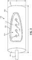
FIG. 2 is an isometric view of an exemplary embodiment of a cylinder for holding articles for use with a customization system; -
FIG. 3 is an exploded view of an exemplary embodiment of a cylinder for holding articles; -
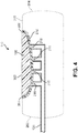
FIG. 4 is a cross-sectional view of an exemplary embodiment of an article disposed on a cylinder; -
FIG. 5 is a schematic view of an exemplary embodiment of a vacuum being applied to a cylinder for holding an article for printing; -
FIG. 6 is a representational view of an exemplary embodiment of using a customization system including a cylinder for holding an article for printing; -
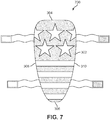
FIG. 7 is a schematic view of an exemplary embodiment of an article having a graphic printed using a customization system including a cylinder; and -
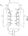
FIG. 8 is an alternate embodiment of a cylinder for holding a pair of articles for printing. -
FIG. 1 is a schematic view of an embodiment ofcustomization system 100. In the embodiments,customization system 100 is intended for use with articles of equipment to be worn. In particular,customization system 100 may include various kinds of provisions for printing a graphic onto an article of equipment to be worn. Moreover, the process of applying graphics may occur after an article has been manufactured. For example, graphics may be applied to an article of equipment after the article has been manufactured. In other cases, graphics may be applied to an article, prior to, and/or during, manufacture. For example, graphics may be applied to a portion of an article prior to being assembled into a finished article. - The term "graphic" as used throughout this detailed description and in the claims refers to any visual design elements including, but not limited to: photos, logos, text, illustrations, lines, shapes, images of various kinds as well as any combinations of these elements. Moreover, the term graphic is not intended to be limiting and could incorporate any number of contiguous or non-contiguous visual features. For example, in one embodiment, a graphic may comprise a logo that is applied to a small region of an article. In another embodiment, a graphic may comprise a large region of color that is applied over one or more regions of an article.
- For clarity, the following detailed description discusses an exemplary embodiment, in which
customization system 100 is used to apply graphics to an article of equipment that is to be worn. In this case, the article of equipment, or simply article, may take the form of a piece of sports equipment, such as a shin guard. However, it should be noted that the other embodiments could be used with any other kinds of articles of equipment to be worn, including, but not limited to: shin guards, knee pads, elbow pads, shoulder pads, as well as any other type of protective equipment. WhileFIG. 1 shows a single article, it will be understood thatcustomization system 100 could be used to apply graphics to two or more articles. -
Customization system 100 may comprise various provisions that are useful in applying a graphic directly to an article. Thecustomization system 100 includes aprinting system 104.Printing system 104 may comprise one or more individual printers. Although a single printer is illustrated inFIG. 1 , other embodiments could incorporate two or more printers that may be networked together. -
Printing system 104 may utilize various types of printing techniques. These may include, but are not limited to: toner-based printing, liquid inkjet printing, solid ink printing, dye-sublimation printing, inkless printing (including thermal printing and UV printing) as well as any other methods of printing. In some cases,printing system 104 may make use of a combination of two or more different printing techniques. The type of printing technique used may vary according to factors including, but not limited to: material of the target article, size and/or geometry of the target article, desired properties of the printed image (such as durability, color, ink density, etc.) as well as printing speed, printing costs and maintenance requirements. - In one embodiment,
printing system 104 may utilize an inkjet printer in which ink droplets may be sprayed onto a substrate, such as the outer surface of an article of equipment. Using an inkjet printer allows for easy variation in color and ink density. This arrangement also allows for some separation between the printer head and the target object, which can facilitate printing directly to objects with some curvature and/or surface texture. - In some embodiments,
customization system 100 may include additional components for mounting various portions ofcustomization system 100. In an exemplary embodiment,customization system 100 may include abase portion 106.Base portion 106 may comprise a substantially flat surface for mounting one or more components ofcustomization system 100. In an exemplary embodiment,printing system 104 may be disposed on a top side ofbase portion 106. In some embodiments,base portion 106 may include astationary platform 108 that comprises a surface for receiving one or more articles. In an exemplary embodiment,stationary platform 108 may be configured to raise an object or an article above the surface ofbase portion 106. In some cases,stationary platform 108 may be fixed approximately in place onbase portion 106. In other cases,stationary platform 108 may be instead be replaced by a movable platform that is configured to move relative tobase portion 106. For example, a movable platform may be provided with a tracked or wheeled arrangement as is known in the art to provide movement relative tobase portion 106. - In some embodiments,
customization system 100 may include aprinting system 104 that is configured to move to various positions. In an exemplary embodiment,printing system 104 may be mounted totracks 112 ofbase portion 106. In some cases,printing system 104 is mounted in a movable manner tobase portion 106, so thatprinting system 104 may slide or travel alongtracks 112. This allowsprinting system 104 to move between various positions alongbase portion 106 in the direction oftracks 112 and relative tostationary platform 108. In other cases,printing system 104 may be configured to be stationary onbase portion 106 and a movable platform, as discussed above, may be used to move an object or article relative toprinting system 104. In still other cases,printing system 104 and a movable platform may be used in combination with one another. - The
customization system 100 is configured to print onto articles of equipment, including, but not limited, to various types of sports equipment. In an exemplary embodiment,customization system 100 may be configured to print onto articles of equipment that have a cylindrical, circular, round, or generally curved configuration including, but not limited to: shin guards, knee pads, elbow pads, shoulder pads, as well as any other type of protective equipment, including individual components of equipment. - In contrast to flat articles, articles of equipment may pose challenges for holding in place to present a surface for printing. Typically, an article of equipment may be worn on a portion of a wearer's body that corresponds to the curvature and shape of the article. Accordingly, in an exemplary embodiment,
customization system 100 may be provided with an apparatus for holding an article to provide a surface for printing. The apparatus for holding the article is configured as acylinder 110. - The
cylinder 110 is provided withcustomization system 100 to hold an article of equipment in a position to allow the exterior surface of the article to be printed. In this configuration,printing system 104 may have a surface for printing onto the article disposed oncylinder 110. - In some embodiments,
customization system 100 may be provided with an apparatus configured to circumferentially rotatecylinder 110. In an exemplary embodiment,customization system 100 may include an actuator that is configured to rotatecylinder 110. In one embodiment, an actuator may include a motor that turns a gear or chain drive to rotatecylinder 110. In other embodiments, a different arrangement may be provided to rotatecylinder 110. For example, in some cases,cylinder 110 may be rotated using a rack and pinion arrangement to translate the linear motion ofprinting system 104 and/or a movable platform into rotational motion ofcylinder 110. In still other cases, other arrangements may be used to impart rotational motion tocylinder 110. In addition, various other devices may be used as is known in the art to rotatecylinder 110. - The
cylinder 110 is configured to receive articles of equipment that have a thickness. Thecylinder 110 includes one or more recesses in the outer surface ofcylinder 110 to accommodate the thickness of an article. In some cases, articles of equipment disposed oncylinder 110 may have a tendency to move whencylinder 110 is rotated. Accordingly,cylinder 110 includes provisions to securely hold an article within the recesses incylinder 110. - A
vacuum system 120 is used to assist with holding an article within the recesses provided incylinder 110.Vacuum system 120 may include avacuum pump 122 that is configured to generate a partial vacuum by evacuating air from a container. In this embodiment, avacuum canister 124 may be in fluid communication withvacuum pump 122.Vacuum canister 124 may serve as the container from whichvacuum pump 122 evacuates air to generate a partial vacuum. In this case, a partial vacuum may be a quantity of gas that is at a lower pressure than the ambient pressure outside ofvacuum canister 124.Vacuum system 120 may include additional components that are configured to supply power and control operation ofvacuum pump 122 andvacuum canister 124. - In an exemplary embodiment,
vacuum system 120 may also include afluid line 126 that is in fluid communication with one or more ofvacuum pump 122,vacuum canister 124, andcylinder 110. With this arrangement,fluid line 126 permits a partial vacuum to be drawn withincylinder 110 to assist with holding an article in place within the recesses oncylinder 110. In addition,vacuum system 120 may include other components that are known to be associated with a vacuum system, including various valves, ports, and connections that open andclose fluid line 126 to apply and/or remove the partial vacuum fromcylinder 110. - Referring now to
FIG. 2 , an exemplary embodiment ofcylinder 110 including one or more recesses in the outer surface ofcylinder 110 to accommodate an article is illustrated. In an exemplary embodiment,cylinder 110 may be a right circular cylinder associated with a length L along a longitudinal direction ofcylinder 110 and a diameter D between opposing points along a circular cross-section ofcylinder 110. In this embodiment,cylinder 110 has anouter surface 200 disposed over the exterior ofcylinder 110. The surface area ofouter surface 200 ofcylinder 110 may be determined from a known geometric formula for determining the surface area of a right circular cylinder (A = 2πrh). In this embodiment, the surface area ofcylinder 110 is equal to DπL. - In other embodiments, different cylinders may be provided with different dimensions, including a larger or smaller diameter and/or a larger or smaller longitudinal length L, than
cylinder 110. In some embodiments, various cylinders may be provided that are sized and dimensioned so as to support different articles of equipment. For example, a cylinder having a larger diameter and/or a larger length that may be provided for supporting a larger article of protective equipment for printing. In another example, a cylinder having a smaller diameter and/or a smaller length that may be provided for supporting a smaller article of equipment for printing. In another example, a cylinder may have sufficient length so that two articles may be positioned adjacent each other length-wise along the cylinder for simultaneous printing. It should be understood that a cylinder of any diameter and/or length may be provided to fit a specific article for printing. - In some embodiments,
cylinder 110 may be described as having afirst end 202 and asecond end 204 disposed oppositefirst end 202.First end 202 andsecond end 204 may be used for purposes of reference to describe the relative location of an article disposed oncylinder 110. In an exemplary embodiment,first end 202 andsecond end 204 ofcylinder 110 may be closed so as to provide an airtight interior within the inside ofcylinder 110. In one embodiment,fluid line 126 may be disposed throughfirst end 202 to place the interior ofcylinder 110 in fluid communication withvacuum system 120. With this arrangement, a partial vacuum may be applied within the interior ofcylinder 110 to assist with holding an article, as described in more detail below. - The
cylinder 110 is provided with one or more recesses inouter surface 200, including arecess 210. Recess 210 may be configured to accommodate and correspond to an article of equipment to be held in place oncylinder 110. In an exemplary embodiment,recess 210 may be configured to have a shape and size that corresponds to the shape and size of the article to be held in place oncylinder 110. Recess 210 also may be configured to have a depth that is approximately equal to the thickness of the article that is to be held in place oncylinder 110. In other embodiments, the size, shape, and/or depth ofrecess 210 may be varied according to the article to be held oncylinder 110. In other embodiments, the size, shape, and/or depth ofrecess 210 may be configured to be a universal size so that many different sizes and shapes of articles may be accommodated by asingle recess 210. For example,recess 210 may have the shape of a quadrilateral, where the size of the quadrilateral may accommodate the largest adult male-sized article and any smaller articles. In another example, a specific ergonomic shape of an article, such as a shin guard, may be accommodated by the size of the recess, where a gap is positioned between the edges of the recess and the edges of the article. The size of the gap may differ for different shapes and sizes of different articles. - In some embodiments,
recess 210 may be configured with anoptional gasket 212 disposed over at least a portion ofrecess 210.Gasket 212 may be made of a flexible material that is configured to provide an airtight seal between an article andrecess 210 so as to hold an article in place oncylinder 110. Suitable materials forgasket 212 may include, but are not limited to: rubber, silicone, or any other flexible materials. In some cases,gasket 212 may extend around a perimeter ofrecess 210 between abottom surface 214 ofrecess 210 andouter surface 200 ofcylinder 110. In other cases,gasket 212 may extend around the perimeter of recess and overbottom surface 214. In the embodiments where the recess is sized and shaped to correspond closely with a specific size and/or shape of article,gasket 212 may extend only a short distance from the edge of the recess into the interior space of the recess. - In the embodiments where
recess 210 is sized and shaped to accommodate more than one size and/or shape of article,gasket 212 may extend a large distance from the edge of the recess into the interior space of the recess, or even cover the entirety ofbottom surface 214. In these embodiments, several interchangeable gaskets of different sizes may be provided to accommodate different articles. - In the embodiments where no gasket is provided, the article itself may be made of a material having sufficient ability to deform to form the seal when the vacuum is pulled. For example, the article may include elastomeric materials such as rubber, silicone, foam, and/or plastics.
- In an exemplary embodiment, one or
more ports 216 may be disposed onbottom surface 214 ofrecess 210 to permit the interior ofcylinder 110 and/orfluid line 126 to be in fluid communication withrecess 210. With this arrangement,ports 216 may allow the negative pressure from the interior ofcylinder 110 provided byvacuum system 120 viafluid line 126 to hold an article disposed withinrecess 210 in place oncylinder 110. In this embodiment, a plurality ofports 216 are disposed alongbottom surface 214 at evenly-spaced intervals. In other embodiments, a larger or smaller number ofports 216 may be provided alongbottom surface 214 ofrecess 210. In addition, the spacing and location ofports 216 may be varied to provide targeted areas of greater vacuum pressure to an article disposed withinrecess 210. For example, in some cases, a portion of an article disposed withinrecess 210 may be heavier than other portions of the article. In this circumstance, a larger number ofports 216 may be disposed at a location corresponding to the heaver portion of the article when disposed inrecess 210 so as to provide additional vacuum pressure to assist with holding the article in place oncylinder 110. - In different embodiments, the recess in
outer surface 200 ofcylinder 110, includingrecess 210, may be formed using different processes. In an exemplary embodiment, a CNC machine or similar apparatus may be used to cut or remove a portion ofcylinder 110 to form the recess at the desired location, including the location ofrecess 210. In other embodiments, a recess inouter surface 200 ofcylinder 110 may be formed using other methods, including, but not limited to molding or casting techniques. - Referring now to
FIG. 3 , an exploded view of an exemplary embodiment ofcylinder 110 for holding articles is illustrated. In this embodiment,cylinder 110 is configured to hold an article of equipment in the form of ashin guard 300. In other embodiments, various other articles may be held usingcylinder 110 or a cylinder specifically configured for a particular article of equipment to be worn. - In this embodiment,
shin guard 300 may be configured to cover a portion of a leg of a wearer. In other embodiments,shin guard 300 may be any type of protective equipment. In an exemplary embodiment,shin guard 300 may have anexterior surface 302.Exterior surface 302 may be configured to face outwards away from the leg of wearer whenshin guard 300 is worn.Shin guard 300 may include atop end 304 and abottom end 306.Top end 304 may be configured to be oriented below a knee of the wearer whenshin guard 300 is worn, whereas bottom end may be configured to be oriented above a foot of the wearer whenshin guard 300 is worn.Shin guard 300 may further include afirst side 308 and asecond side 310.First side 308 andsecond side 310 may extend along the length ofshin guard 300 on opposite sides betweentop end 304 andbottom end 306. - As shown in
FIG. 3 , in some embodiments,recess 210 inouter surface 200 ofcylinder 110 may be configured to receive an article, includingshin guard 300. The size and dimensions ofrecess 210 are configured to correspond to the size and dimensions ofshin guard 300. In an exemplary embodiment,recess 210 is provided withgasket 212 that is configured to contact at least the perimeter ofshin guard 300, including along a portion oftop end 304,first side 308,bottom end 306, andsecond side 310. In addition,shin guard 300 may be placed intorecess 210 such thatexterior surface 302 ofshin guard 300 is oriented facing away fromcylinder 110. With this arrangement,exterior surface 302 ofshin guard 300 may be prepared for printing thereupon. -
FIGS. 4 and5 illustrate an exemplary embodiment of an article disposed withinrecess 210 oncylinder 110 and being held in place using a partial vacuum applied tocylinder 110. Referring toFIG. 4 , in this embodiment,shin guard 300 is disposed withinrecess 210 oncylinder 110. In one embodiment,gasket 212 may be provided withinrecess 210 and assist with providing an airtight seal betweenshin guard 300 andcylinder 110. In this embodiment,cylinder 110 is shown in phantom to illustrate the interior ofcylinder 110, includingfluid line 126 andports 216. As shown inFIG. 4 ,ports 216 allow fluid communication betweenfluid line 126 andrecess 210. In this embodiment,ports 216 include four ports disposed belowshin guard 300. In other embodiments, a larger or smaller number of ports may be provided. In addition, in other embodiments,first end 202 andsecond end 204 ofcylinder 110 may be closed to create a sealed interior withincylinder 110 andports 216 may be in fluid communication with the interior ofcylinder 110, which may be supplied with a partial vacuum fromfluid line 126. - Referring now to
FIG. 5 ,vacuum system 120 may be used to apply a partial vacuum toshin guard 300 viafluid line 126 andports 216. In this embodiment, the negative pressure associated with partial vacuum generated byvacuum system 120 causesshin guard 300 to be pulled intorecess 210 againstgasket 212 to form an airtight seal. This negative pressure caused by the partial vacuum serves to holdshin guard 300 in place oncylinder 110. In an exemplary embodiment, the vacuum pressure provided viafluid line 126 andports 216 is sufficient to holdshin guard 300 in place withinrecess 210 whilecylinder 110 rotates during the printing process. - In some embodiments, the partial vacuum applied to
shin guard 300 viafluid line 126 andports 216 may also serve to causeexterior surface 302 ofshin guard 300 to be approximately even with theouter surface 200 of cylinder. With this arrangement,shin guard 300 may present a substantially uniform surface for printing usingprinting system 104, described below. - Referring now to
FIG. 6 , a representational view ofshin guard 300 being held withinrecess 210 oncylinder 110 during printing is illustrated. In this embodiment,shin guard 300 is disposed withrecess 210 ofcylinder 110. In an exemplary embodiment, negative pressure provided from a partial vacuum generated byvacuum system 120 is used to holdshin guard 300 in place oncylinder 110 viafluid line 126. With this arrangement,exterior surface 302 ofshin guard 300 is configured for printing thereupon. - In some embodiments,
customization system 100 may be used for printing a graphic 600 ontoshin guard 300.Graphic 600 could be stored using a computer system in communication withcustomization system 100 or may be retrieved from another source. In other embodiments, graphic 600 may be designed using software associated withcustomization system 100. In one embodiment, graphic 600 may be a custom designed image that may be applied to an article for the purposes of customizing the article to suit a particular customer or user. In some embodiments,customization system 100 may be used to print graphic 600 onto an article of equipment. In this embodiment,shin guard 300 has been mounted ontocylinder 110 for printing graphic 600 thereupon. - As described above,
customization system 100 includesprinting system 104 having aprinter 602. In an exemplary embodiment,printer 602 may be mounted upon one ormore rails 604 to allowprinter 602 to move or translate along an x-axis aligned with the longitudinal direction ofshin guard 300 disposed oncylinder 110. In cases whereprinter 602 includes an inkjet printer, one or more printheads, including aprinthead 606, may be configured to depositink droplets 608 onto a substrate. In this embodiment,printhead 606 is configured to sprayink droplets 608 ontoexterior surface 302 ofshin guard 300. As described above,shin guard 300 held withinrecess 210 ofcylinder 110 may be configured to circumferentially rotate during printing so as to rotateshin guard 300 for printing. - In an exemplary embodiment, rotation of
shin guard 300 and/or movement ofprinter 602 alongrails 604 may allow graphic 600 to be printed onto substantially all ofexterior surface 302 ofshin guard 300. In one embodiment, graphic 600 may be printed overexterior surface 302 ofshin guard 300 through approximately 180 degrees of rotation. In some cases, graphic 600 may be printed overexterior surface 302 ofshin guard 300 through less than 180 degrees of rotation depending on the size and shape ofshin guard 300. With this arrangement, graphic 600 may be printed across the exterior surface of an article disposed within a recess incylinder 110. In other embodiments, more or less of an article may be printed upon, including only a portion ofexterior surface 302 ofshin guard 300. - In addition, in other embodiments, multiple graphics of varying sizes, colors, and/or configurations may be printed on substantially all of
exterior surface 302 ofshin guard 300 or on one or more portions ofshin guard 300. In addition, in the present embodiment,printhead 606 may be located a fixed, predetermined distance fromexterior surface 302 ofshin guard 300. In other embodiments, however,printhead 606 may be configured to move in a vertical direction relative toexterior surface 302. - In some embodiments, the layout of graphic 600 may be processed by a computer or processor into a series of commands for moving
printer 602 alongrails 604 and/or rotatingshin guard 300 disposed oncylinder 110 to depositink droplets 608 onto the appropriate locations onexterior surface 302 to generate graphic 600 ontoshin guard 300. In an exemplary embodiment, a suitable computer system that may be used for preparing graphic 600 or other graphics for printing is disclosed in co-pending and commonly ownedU.S. Patent Application Serial No. 61/808,543 to Miller et al. -
FIG. 7 illustrates an exemplary embodiment of a printedarticle 700 that has been printed using the system and process described herein. As shown inFIG. 7 , printedarticle 700 isshin guard 300 that has had graphic 600 printed uponexterior surface 302 usingcylinder 110. After printing graphic 600 ontoshin guard 300 usingprinting system 104, described above,shin guard 300 may be removed fromcylinder 110 to result in printedarticle 700. In some embodiments, printedarticle 700 may be completed by adding additional accessories or components that assist with wearing the article on a user. - In this embodiment, graphic 600 is printed across substantially all of
exterior surface 302. As noted above, in other embodiments, less than the entirety ofexterior surface 302 may be printed upon. By usingcylinder 110 having a recess to accommodateshin guard 300 andvacuum system 120 to generate a partial vacuum to holdshin guard 300 in place, graphic 600 may be printed acrossexterior surface 302 of printedarticle 700. - It should be understood that while in the previous embodiments, an exemplary article of equipment in the form of a single shin guard has been illustrated, the principles described herein may be similarly applied to a second identical article to provide a pair of articles, or other similar articles of equipment that are worn in pairs or with multiple component parts.
- In some embodiments, a cylinder may be provided that is configured to hold a pair of articles to allow printing of a complete pair of articles during the same printing process. Referring now to
FIG. 8 , an alternate embodiment of acylinder 800 is illustrated. In an exemplary embodiment,cylinder 800 may be substantially similar tocylinder 110, but provided with two recesses in anexterior surface 802 to accommodate two substantially similar articles of equipment forming a pair of articles. Other components ofcylinder 800 may be substantially similar to components ofcylinder 110, includingfluid line 126. In addition,cylinder 800 may include afirst end 804 and asecond end 806 that are substantially similar tofirst end 202 andsecond end 204, described above. - In this embodiment,
cylinder 800 includes afirst recess 810 and asecond recess 820. In an exemplary embodiment,first recess 810 andsecond recess 820 may be disposed on opposite sides ofcylinder 800.First recess 810 andsecond recess 820 may be substantially similar torecess 210, described above. In an exemplary embodiment,first recess 810 may includefirst gasket 812 disposed around at least a perimeter offirst recess 810.First gasket 812 may be substantially similar togasket 212, described above. In some cases,first gasket 812 may additionally extend over the bottom surface offirst recess 810. In addition,first recess 810 may include a plurality ofports 816 disposed in the bottom surface that are in fluid communication withfluid line 126.Ports 816 may be substantially similar toports 216, described above, and may allow negative pressure from the interior ofcylinder 800 provided byvacuum system 120 viafluid line 126 to hold an article disposed withinfirst recess 810 in place oncylinder 800. - Similarly, in an exemplary embodiment,
second recess 820 may includesecond gasket 822 disposed around at least a perimeter ofsecond recess 820.Second gasket 822 may be substantially similar togasket 212, described above. In some cases,second gasket 822 may additionally extend over the bottom surface ofsecond recess 820. In addition,second recess 820 may include a plurality ofports 826 disposed in the bottom surface that are in fluid communication withfluid line 126.Ports 826 may be substantially similar toports 216, described above, and may allow negative pressure from the interior ofcylinder 800 provided byvacuum system 120 viafluid line 126 to hold an article disposed withinsecond recess 820 in place oncylinder 800. - In some embodiments,
cylinder 800 may be configured to receive a pair of articles, including afirst article 830 and asecond article 832. In an exemplary embodiment,first article 830 andsecond article 832 may be a pair of shin guards that are to be worn on the right and left legs of a wearer. In this embodiment,first recess 810 is configured to receivefirst article 830 andsecond recess 820 is configured to receivesecond article 832. As noted above with reference to recess 210,first recess 810 and/orsecond recess 820 may have a corresponding shape asfirst article 830 and/orsecond article 832 and may be sized and dimensioned to correspond with the size and dimensions offirst article 830 and/orsecond article 832. - In an exemplary embodiment,
vacuum system 120 may be used to apply a partial vacuum tofirst article 830 and/orsecond article 832 viafluid line 126 andports 816 and/orports 826. The negative pressure associated with the partial vacuum generated byvacuum system 120 causesfirst article 830 and/orsecond article 832 to be pulled intofirst recess 810 and/orsecond recess 820 againstfirst gasket 812 and/orsecond gasket 822 to form an airtight seal. This negative pressure caused by the partial vacuum serves to holdfirst article 830 and/orsecond article 832 in place oncylinder 800 whilecylinder 800 rotates during the printing process. - With this arrangement, a graphic may be applied to
first article 830 and/orsecond article 832 during the same printing process to produce a finished pair of articles. In other embodiments, cylinders having additional recesses may be provided to accommodate additional articles so that multiple articles may be printed during the same printing process. - While various embodiments of the invention have been described, the description is intended to be exemplary, rather than limiting and it will be apparent to those of ordinary skill in the art that many more embodiments and implementations are possible that are within the scope of the invention.
Claims (7)
- A customization system (100) for printing a graphic onto an article (830,832) of equipment to be worn, comprising:a printing system (104), including a printer (602);a cylinder (800) for holding the article (830,832) in proximity to the printer (602);a vacuum system (120) in fluid communication with the cylinder (800); andwherein the vacuum system (120) is configured to apply a partial vacuum to the article (830,832), characterised in that the article (830,832) is configured to be disposed within a recess (810,820) in an outer surface of the cylinder (800) and in that the said partial vacuum holds the article (830,832) within the recess (810,820).
- The customization system (100) according to claim 1, wherein the cylinder (800) is configured to rotate relative to the printer (602) to allow the printer (602) to print a graphic onto the article (830,832).
- The customization system (100) according to claim 1, wherein the recess (810,820) can accommodate a specific ergonomic shape, or the recess (810,820) has the shape of a quadrilateral.
- The customization system (100) according to claim 1, wherein the cylinder (800) further comprises a fluid line connected to the cylinder (800) at one end; and
a plurality of ports in fluid communication with the fluid line. - The customization system (100) according to claim 4, wherein the plurality of ports are disposed along a bottom surface of the recess (810,820).
- The customization system (100) according to claim 1, further comprising a gasket (812) disposed along at least a perimeter of the recess (810,820).
- The customization system (100) according to claim 6, wherein the gasket (812) forms an airtight seal with the article (830,832) when the vacuum system (120) applies the partial vacuum and the article (830, 832) is disposed within the recess (810, 820).
Priority Applications (1)
| Application Number | Priority Date | Filing Date | Title |
|---|---|---|---|
| EP19213090.4A EP3636444B1 (en) | 2013-04-04 | 2014-04-03 | Vacuum cylinder with recessed portions for holding articles for printing |
Applications Claiming Priority (3)
| Application Number | Priority Date | Filing Date | Title |
|---|---|---|---|
| US201361808569P | 2013-04-04 | 2013-04-04 | |
| US14/242,713 US9409414B2 (en) | 2013-04-04 | 2014-04-01 | Vacuum cylinder with recessed portions for holding articles for printing |
| PCT/US2014/032798 WO2014165658A1 (en) | 2013-04-04 | 2014-04-03 | Vacuum cylinder with recessed portions for holding articles for printing |
Related Child Applications (1)
| Application Number | Title | Priority Date | Filing Date |
|---|---|---|---|
| EP19213090.4A Division EP3636444B1 (en) | 2013-04-04 | 2014-04-03 | Vacuum cylinder with recessed portions for holding articles for printing |
Publications (2)
| Publication Number | Publication Date |
|---|---|
| EP2941352A1 EP2941352A1 (en) | 2015-11-11 |
| EP2941352B1 true EP2941352B1 (en) | 2019-12-11 |
Family
ID=51654132
Family Applications (2)
| Application Number | Title | Priority Date | Filing Date |
|---|---|---|---|
| EP19213090.4A Active EP3636444B1 (en) | 2013-04-04 | 2014-04-03 | Vacuum cylinder with recessed portions for holding articles for printing |
| EP14732990.8A Active EP2941352B1 (en) | 2013-04-04 | 2014-04-03 | Vacuum cylinder with recessed portions for holding articles for printing |
Family Applications Before (1)
| Application Number | Title | Priority Date | Filing Date |
|---|---|---|---|
| EP19213090.4A Active EP3636444B1 (en) | 2013-04-04 | 2014-04-03 | Vacuum cylinder with recessed portions for holding articles for printing |
Country Status (6)
| Country | Link |
|---|---|
| US (2) | US9409414B2 (en) |
| EP (2) | EP3636444B1 (en) |
| JP (1) | JP6298525B2 (en) |
| KR (1) | KR101860989B1 (en) |
| CN (1) | CN105073432B (en) |
| WO (1) | WO2014165658A1 (en) |
Families Citing this family (32)
| Publication number | Priority date | Publication date | Assignee | Title |
|---|---|---|---|---|
| US9320316B2 (en) | 2013-03-14 | 2016-04-26 | Under Armour, Inc. | 3D zonal compression shoe |
| US9321257B2 (en) | 2013-04-04 | 2016-04-26 | Nike, Inc. | Cylinder with recessed portions for holding tubular articles for printing |
| US9409414B2 (en) | 2013-04-04 | 2016-08-09 | Nike, Inc. | Vacuum cylinder with recessed portions for holding articles for printing |
| US10259104B2 (en) * | 2013-10-28 | 2019-04-16 | Nikon Corporation | Precision clamp |
| US10010133B2 (en) | 2015-05-08 | 2018-07-03 | Under Armour, Inc. | Midsole lattice with hollow tubes for footwear |
| US10010134B2 (en) | 2015-05-08 | 2018-07-03 | Under Armour, Inc. | Footwear with lattice midsole and compression insert |
| US10039343B2 (en) | 2015-05-08 | 2018-08-07 | Under Armour, Inc. | Footwear including sole assembly |
| US10035169B2 (en) * | 2015-05-21 | 2018-07-31 | Nike, Inc. | Method and apparatus for retaining and transferring an article |
| DE102015212099B4 (en) | 2015-06-29 | 2022-01-27 | Adidas Ag | soles for sports shoes |
| CN105584220A (en) * | 2016-03-15 | 2016-05-18 | 海宁酷彩数码科技有限公司 | 360-degree rotary type ink jetting device used for inkjet printing of socks |
| US10034519B2 (en) | 2016-06-16 | 2018-07-31 | Adidas Ag | UV curable lattice microstructure for footwear |
| US10575588B2 (en) | 2017-03-27 | 2020-03-03 | Adidas Ag | Footwear midsole with warped lattice structure and method of making the same |
| US10932521B2 (en) | 2017-03-27 | 2021-03-02 | Adidas Ag | Footwear midsole with warped lattice structure and method of making the same |
| US20180281306A1 (en) | 2017-04-03 | 2018-10-04 | Xerox Corporation | Universal part gripper using 3-d printed mounting plate |
| US10093112B1 (en) * | 2017-06-13 | 2018-10-09 | Xerox Corporation | Object holder for a direct-to-object printer |
| US10779614B2 (en) | 2017-06-21 | 2020-09-22 | Under Armour, Inc. | Cushioning for a sole structure of performance footwear |
| CN107379786B (en) * | 2017-08-21 | 2019-05-24 | 浙江宝娜斯袜业有限公司 | A kind of digital printing system and the seamless tubular dress ornament of digit printing |
| CN108156765B (en) * | 2018-02-11 | 2019-05-31 | 西安瑞特三维科技有限公司 | The device and method of polyimide media layer and electronic circuit is prepared on a kind of curved surface |
| USD879428S1 (en) | 2018-02-15 | 2020-03-31 | Adidas Ag | Sole |
| USD880131S1 (en) | 2018-02-15 | 2020-04-07 | Adidas Ag | Sole |
| USD879434S1 (en) | 2018-02-15 | 2020-03-31 | Adidas Ag | Sole |
| USD882227S1 (en) | 2018-02-15 | 2020-04-28 | Adidas Ag | Sole |
| USD880120S1 (en) | 2018-02-15 | 2020-04-07 | Adidas Ag | Sole |
| USD880122S1 (en) | 2018-02-15 | 2020-04-07 | Adidas Ag | Sole |
| KR102145972B1 (en) * | 2018-03-26 | 2020-08-19 | 주식회사 레이젠 | 3d nail printer and method for 3d nail printing using the same |
| USD890485S1 (en) | 2018-11-12 | 2020-07-21 | Adidas Ag | Shoe |
| USD1022425S1 (en) | 2020-10-07 | 2024-04-16 | Adidas Ag | Shoe |
| US11786008B2 (en) | 2020-10-07 | 2023-10-17 | Adidas Ag | Footwear with 3-D printed midsole |
| USD980594S1 (en) | 2020-10-13 | 2023-03-14 | Adidas Ag | Shoe |
| US20220110406A1 (en) | 2020-10-13 | 2022-04-14 | Adidas Ag | Footwear midsole with 3-d printed mesh having an anisotropic structure and methods of making the same |
| USD980595S1 (en) | 2020-10-13 | 2023-03-14 | Adidas Ag | Shoe |
| US11589647B2 (en) | 2020-10-13 | 2023-02-28 | Adidas Ag | Footwear midsole with anisotropic mesh and methods of making the same |
Citations (2)
| Publication number | Priority date | Publication date | Assignee | Title |
|---|---|---|---|---|
| FR2308508A1 (en) * | 1975-04-21 | 1976-11-19 | Nard Institute Ltd | Clothing article printing process - stretches and holds over supporting roller |
| US6481347B2 (en) * | 1998-04-14 | 2002-11-19 | Ackley Machine Corporation | Method and apparatus for spin printing indicia on pellet shaped articles |
Family Cites Families (46)
| Publication number | Priority date | Publication date | Assignee | Title |
|---|---|---|---|---|
| US701841A (en) | 1901-09-11 | 1902-06-10 | George J Burns | Roll and plaiting-machines. |
| US1830638A (en) | 1930-06-18 | 1931-11-03 | Louis N D Williams | Hosiery printing apparatus |
| US2249939A (en) | 1940-09-03 | 1941-07-22 | Alfred F Branan | Hose decorating method and apparatus |
| US2459538A (en) | 1944-11-14 | 1949-01-18 | Markem Machine Co | Machine for marking on cylindrical articles |
| GB736650A (en) | 1953-08-10 | 1955-09-14 | Samar Machines Ltd | Apparatus for printing knitted articles of footwear |
| US2920556A (en) | 1956-11-21 | 1960-01-12 | Owens Illinois Glass Co | Machine for decorating round surfaces |
| US2974838A (en) | 1956-12-27 | 1961-03-14 | Burlington Industries Inc | Sock printing machine, method, and article |
| US3794314A (en) | 1972-01-13 | 1974-02-26 | Coburn Optical Ind | Vacuum chuck for ophthalmic lens finishing machinery |
| US4303459A (en) | 1978-12-04 | 1981-12-01 | Kurt Kleber | Method of making textured patterns on originally smooth webs of fabrics, and method of partially printing the same |
| US4561642A (en) | 1984-03-16 | 1985-12-31 | Parque John P | Portable vacuum holding device |
| US4590854A (en) | 1984-04-06 | 1986-05-27 | Anderson Ronald C | Screen printing method and apparatus |
| US4619384A (en) | 1985-10-15 | 1986-10-28 | Chu Chia Shih | Printing or drawing mold for stockings |
| US4846483A (en) | 1988-07-27 | 1989-07-11 | Acebo Company | Mandrel system for receiving cup having side wall ribbed interior surface for printing on exterior surface of side wall |
| US4930413A (en) | 1989-04-07 | 1990-06-05 | Artwave America Inc. | Apparatus and method for three-dimensional screen printing |
| CN1088159A (en) | 1991-10-02 | 1994-06-22 | 汉纳技术有限公司 | The device and the technology that are used for textile dyeing |
| JPH0781050A (en) * | 1993-09-20 | 1995-03-28 | Video Jietsuto Japan Kk | Printing of tablet or capsule |
| GB2291011A (en) | 1994-07-05 | 1996-01-17 | Anthony Philip Magill | Printing device |
| US5660380A (en) | 1995-08-15 | 1997-08-26 | W. L. Gore & Associates, Inc. | Vacuum fixture and method for dimensioning and manipulating materials |
| US5831641A (en) | 1996-11-27 | 1998-11-03 | Eugene Gollings | Methods and apparatus for imprinting indecia on a three dimensional article |
| JP2990594B2 (en) | 1996-12-13 | 1999-12-13 | ニューストロング販売 株式会社 | Vacuum chuck |
| US6014162A (en) | 1997-08-18 | 2000-01-11 | Eastman Kodak Company | Vacuum imaging drum with media contours |
| US5878658A (en) * | 1997-12-01 | 1999-03-09 | Ackley Machine Corporation | Apparatus and method for marking two sides of a pellet-shaped article |
| US6267054B1 (en) | 1999-03-12 | 2001-07-31 | Creo Products Inc. | Retaining apparatus and method for holding printing plates on a vacuum drum |
| US6254081B1 (en) | 1999-06-03 | 2001-07-03 | Hewlett-Packard Company | Regulating vacuum hold of media in a printer |
| CN2390749Y (en) | 1999-07-14 | 2000-08-09 | 赖正福 | Transfer printing apparatus for socks |
| US20030035870A1 (en) * | 2000-01-07 | 2003-02-20 | E. Michael Ackley, Jr. | Method to print multicolor images on edible pieces |
| JP2001270096A (en) * | 2000-03-27 | 2001-10-02 | Asutekku Kk | Ink jet printer |
| US6729235B2 (en) | 2001-04-30 | 2004-05-04 | Eastman Kodak Company | Imaging apparatus and imaging drum having material clamp |
| GB2379414A (en) * | 2001-09-10 | 2003-03-12 | Seiko Epson Corp | Method of forming a large flexible electronic display on a substrate using an inkjet head(s) disposed about a vacuum roller holding the substrate |
| JP4124052B2 (en) * | 2003-08-06 | 2008-07-23 | 松下電器産業株式会社 | Screen printing apparatus and screen printing method |
| US7946668B2 (en) | 2006-10-13 | 2011-05-24 | Fujifilm Dimatix, Inc. | Printing on a rotating surface |
| US7963224B2 (en) | 2007-03-23 | 2011-06-21 | Hewlett-Packard Development Company, L.P. | Drum having a polymer layer with channels on a metal cylinder |
| DE102009013477B4 (en) * | 2009-03-19 | 2012-01-12 | Khs Gmbh | Printing device for printing on bottles or similar containers |
| US8881652B2 (en) | 2009-08-13 | 2014-11-11 | Jann Middo | Printing template |
| CN201703004U (en) | 2010-05-19 | 2011-01-12 | 彰绅精密工业股份有限公司 | Metal printed formwork |
| KR101246987B1 (en) | 2010-11-17 | 2013-04-01 | 김근수 | UV Vaccum Sublimination Transfer Printing Device |
| CN102555524A (en) * | 2010-12-25 | 2012-07-11 | 富葵精密组件(深圳)有限公司 | Automatic jet printing machine |
| PL3395176T3 (en) * | 2011-02-10 | 2020-11-30 | Gea Food Solutions Bakel B.V. | Food forming drum |
| KR101103918B1 (en) * | 2011-05-30 | 2012-01-12 | 김동각 | Printing apparatus and printing method for paper cup |
| JP6004169B2 (en) * | 2011-09-02 | 2016-10-05 | セイコーエプソン株式会社 | Inkjet printing device |
| KR101168660B1 (en) * | 2011-12-23 | 2012-07-25 | 김동각 | Printing apparatus for paper cup |
| US9297097B2 (en) | 2012-06-22 | 2016-03-29 | Nike, Inc. | Knit article of apparel and apparel printing system and method |
| CN202742813U (en) * | 2012-07-10 | 2013-02-20 | 李永红 | Digital inkjet decorating machine for flexible cylinder |
| US9409414B2 (en) | 2013-04-04 | 2016-08-09 | Nike, Inc. | Vacuum cylinder with recessed portions for holding articles for printing |
| US9321257B2 (en) * | 2013-04-04 | 2016-04-26 | Nike, Inc. | Cylinder with recessed portions for holding tubular articles for printing |
| US9004675B2 (en) | 2013-04-04 | 2015-04-14 | Nike, Inc. | Image correction with 3D printing |
-
2014
- 2014-04-01 US US14/242,713 patent/US9409414B2/en active Active
- 2014-04-03 EP EP19213090.4A patent/EP3636444B1/en active Active
- 2014-04-03 EP EP14732990.8A patent/EP2941352B1/en active Active
- 2014-04-03 WO PCT/US2014/032798 patent/WO2014165658A1/en active Application Filing
- 2014-04-03 CN CN201480019118.7A patent/CN105073432B/en active Active
- 2014-04-03 KR KR1020157030201A patent/KR101860989B1/en active IP Right Grant
- 2014-04-03 JP JP2016506606A patent/JP6298525B2/en active Active
-
2016
- 2016-06-30 US US15/198,388 patent/US10259241B2/en active Active
Patent Citations (2)
| Publication number | Priority date | Publication date | Assignee | Title |
|---|---|---|---|---|
| FR2308508A1 (en) * | 1975-04-21 | 1976-11-19 | Nard Institute Ltd | Clothing article printing process - stretches and holds over supporting roller |
| US6481347B2 (en) * | 1998-04-14 | 2002-11-19 | Ackley Machine Corporation | Method and apparatus for spin printing indicia on pellet shaped articles |
Also Published As
| Publication number | Publication date |
|---|---|
| US9409414B2 (en) | 2016-08-09 |
| US10259241B2 (en) | 2019-04-16 |
| CN105073432A (en) | 2015-11-18 |
| EP3636444A1 (en) | 2020-04-15 |
| KR20150132568A (en) | 2015-11-25 |
| JP2016521219A (en) | 2016-07-21 |
| WO2014165658A1 (en) | 2014-10-09 |
| EP3636444B1 (en) | 2022-06-29 |
| US20140300675A1 (en) | 2014-10-09 |
| US20160303876A1 (en) | 2016-10-20 |
| CN105073432B (en) | 2018-03-13 |
| KR101860989B1 (en) | 2018-07-05 |
| WO2014165658A8 (en) | 2015-10-15 |
| EP2941352A1 (en) | 2015-11-11 |
| JP6298525B2 (en) | 2018-03-20 |
Similar Documents
| Publication | Publication Date | Title |
|---|---|---|
| EP2941352B1 (en) | Vacuum cylinder with recessed portions for holding articles for printing | |
| EP2941353B1 (en) | Cylinder with recessed portions for holding tubular articles for printing | |
| US9102167B2 (en) | Method of printing onto apparel and apparatus | |
| JP6903010B2 (en) | Digital press and method | |
| JP6433495B2 (en) | Device for printing closures of containers | |
| US9193176B2 (en) | Systems and methods for printing indicia on latex surfaces in motion | |
| JP7103918B2 (en) | Tablet printing equipment |
Legal Events
| Date | Code | Title | Description |
|---|---|---|---|
| PUAI | Public reference made under article 153(3) epc to a published international application that has entered the european phase |
Free format text: ORIGINAL CODE: 0009012 |
|
| 17P | Request for examination filed |
Effective date: 20150806 |
|
| AK | Designated contracting states |
Kind code of ref document: A1 Designated state(s): AL AT BE BG CH CY CZ DE DK EE ES FI FR GB GR HR HU IE IS IT LI LT LU LV MC MK MT NL NO PL PT RO RS SE SI SK SM TR |
|
| AX | Request for extension of the european patent |
Extension state: BA ME |
|
| DAX | Request for extension of the european patent (deleted) | ||
| STAA | Information on the status of an ep patent application or granted ep patent |
Free format text: STATUS: EXAMINATION IS IN PROGRESS |
|
| 17Q | First examination report despatched |
Effective date: 20170919 |
|
| GRAP | Despatch of communication of intention to grant a patent |
Free format text: ORIGINAL CODE: EPIDOSNIGR1 |
|
| STAA | Information on the status of an ep patent application or granted ep patent |
Free format text: STATUS: GRANT OF PATENT IS INTENDED |
|
| INTG | Intention to grant announced |
Effective date: 20190528 |
|
| GRAS | Grant fee paid |
Free format text: ORIGINAL CODE: EPIDOSNIGR3 |
|
| RIN1 | Information on inventor provided before grant (corrected) |
Inventor name: MORRISON, CATHERINE, R. Inventor name: MILLER, TODD, W. |
|
| GRAA | (expected) grant |
Free format text: ORIGINAL CODE: 0009210 |
|
| STAA | Information on the status of an ep patent application or granted ep patent |
Free format text: STATUS: THE PATENT HAS BEEN GRANTED |
|
| AK | Designated contracting states |
Kind code of ref document: B1 Designated state(s): AL AT BE BG CH CY CZ DE DK EE ES FI FR GB GR HR HU IE IS IT LI LT LU LV MC MK MT NL NO PL PT RO RS SE SI SK SM TR |
|
| REG | Reference to a national code |
Ref country code: GB Ref legal event code: FG4D |
|
| REG | Reference to a national code |
Ref country code: CH Ref legal event code: EP |
|
| REG | Reference to a national code |
Ref country code: AT Ref legal event code: REF Ref document number: 1211801 Country of ref document: AT Kind code of ref document: T Effective date: 20191215 |
|
| REG | Reference to a national code |
Ref country code: DE Ref legal event code: R096 Ref document number: 602014058217 Country of ref document: DE |
|
| REG | Reference to a national code |
Ref country code: IE Ref legal event code: FG4D |
|
| REG | Reference to a national code |
Ref country code: NL Ref legal event code: MP Effective date: 20191211 |
|
| REG | Reference to a national code |
Ref country code: LT Ref legal event code: MG4D |
|
| PG25 | Lapsed in a contracting state [announced via postgrant information from national office to epo] |
Ref country code: BG Free format text: LAPSE BECAUSE OF FAILURE TO SUBMIT A TRANSLATION OF THE DESCRIPTION OR TO PAY THE FEE WITHIN THE PRESCRIBED TIME-LIMIT Effective date: 20200311 Ref country code: FI Free format text: LAPSE BECAUSE OF FAILURE TO SUBMIT A TRANSLATION OF THE DESCRIPTION OR TO PAY THE FEE WITHIN THE PRESCRIBED TIME-LIMIT Effective date: 20191211 Ref country code: GR Free format text: LAPSE BECAUSE OF FAILURE TO SUBMIT A TRANSLATION OF THE DESCRIPTION OR TO PAY THE FEE WITHIN THE PRESCRIBED TIME-LIMIT Effective date: 20200312 Ref country code: NO Free format text: LAPSE BECAUSE OF FAILURE TO SUBMIT A TRANSLATION OF THE DESCRIPTION OR TO PAY THE FEE WITHIN THE PRESCRIBED TIME-LIMIT Effective date: 20200311 Ref country code: LV Free format text: LAPSE BECAUSE OF FAILURE TO SUBMIT A TRANSLATION OF THE DESCRIPTION OR TO PAY THE FEE WITHIN THE PRESCRIBED TIME-LIMIT Effective date: 20191211 Ref country code: SE Free format text: LAPSE BECAUSE OF FAILURE TO SUBMIT A TRANSLATION OF THE DESCRIPTION OR TO PAY THE FEE WITHIN THE PRESCRIBED TIME-LIMIT Effective date: 20191211 Ref country code: LT Free format text: LAPSE BECAUSE OF FAILURE TO SUBMIT A TRANSLATION OF THE DESCRIPTION OR TO PAY THE FEE WITHIN THE PRESCRIBED TIME-LIMIT Effective date: 20191211 |
|
| PG25 | Lapsed in a contracting state [announced via postgrant information from national office to epo] |
Ref country code: HR Free format text: LAPSE BECAUSE OF FAILURE TO SUBMIT A TRANSLATION OF THE DESCRIPTION OR TO PAY THE FEE WITHIN THE PRESCRIBED TIME-LIMIT Effective date: 20191211 Ref country code: RS Free format text: LAPSE BECAUSE OF FAILURE TO SUBMIT A TRANSLATION OF THE DESCRIPTION OR TO PAY THE FEE WITHIN THE PRESCRIBED TIME-LIMIT Effective date: 20191211 |
|
| PG25 | Lapsed in a contracting state [announced via postgrant information from national office to epo] |
Ref country code: AL Free format text: LAPSE BECAUSE OF FAILURE TO SUBMIT A TRANSLATION OF THE DESCRIPTION OR TO PAY THE FEE WITHIN THE PRESCRIBED TIME-LIMIT Effective date: 20191211 |
|
| PG25 | Lapsed in a contracting state [announced via postgrant information from national office to epo] |
Ref country code: ES Free format text: LAPSE BECAUSE OF FAILURE TO SUBMIT A TRANSLATION OF THE DESCRIPTION OR TO PAY THE FEE WITHIN THE PRESCRIBED TIME-LIMIT Effective date: 20191211 Ref country code: EE Free format text: LAPSE BECAUSE OF FAILURE TO SUBMIT A TRANSLATION OF THE DESCRIPTION OR TO PAY THE FEE WITHIN THE PRESCRIBED TIME-LIMIT Effective date: 20191211 Ref country code: CZ Free format text: LAPSE BECAUSE OF FAILURE TO SUBMIT A TRANSLATION OF THE DESCRIPTION OR TO PAY THE FEE WITHIN THE PRESCRIBED TIME-LIMIT Effective date: 20191211 Ref country code: NL Free format text: LAPSE BECAUSE OF FAILURE TO SUBMIT A TRANSLATION OF THE DESCRIPTION OR TO PAY THE FEE WITHIN THE PRESCRIBED TIME-LIMIT Effective date: 20191211 Ref country code: RO Free format text: LAPSE BECAUSE OF FAILURE TO SUBMIT A TRANSLATION OF THE DESCRIPTION OR TO PAY THE FEE WITHIN THE PRESCRIBED TIME-LIMIT Effective date: 20191211 Ref country code: PT Free format text: LAPSE BECAUSE OF FAILURE TO SUBMIT A TRANSLATION OF THE DESCRIPTION OR TO PAY THE FEE WITHIN THE PRESCRIBED TIME-LIMIT Effective date: 20200506 |
|
| PG25 | Lapsed in a contracting state [announced via postgrant information from national office to epo] |
Ref country code: SM Free format text: LAPSE BECAUSE OF FAILURE TO SUBMIT A TRANSLATION OF THE DESCRIPTION OR TO PAY THE FEE WITHIN THE PRESCRIBED TIME-LIMIT Effective date: 20191211 Ref country code: IS Free format text: LAPSE BECAUSE OF FAILURE TO SUBMIT A TRANSLATION OF THE DESCRIPTION OR TO PAY THE FEE WITHIN THE PRESCRIBED TIME-LIMIT Effective date: 20200411 Ref country code: SK Free format text: LAPSE BECAUSE OF FAILURE TO SUBMIT A TRANSLATION OF THE DESCRIPTION OR TO PAY THE FEE WITHIN THE PRESCRIBED TIME-LIMIT Effective date: 20191211 |
|
| REG | Reference to a national code |
Ref country code: DE Ref legal event code: R097 Ref document number: 602014058217 Country of ref document: DE |
|
| REG | Reference to a national code |
Ref country code: AT Ref legal event code: MK05 Ref document number: 1211801 Country of ref document: AT Kind code of ref document: T Effective date: 20191211 |
|
| PLBE | No opposition filed within time limit |
Free format text: ORIGINAL CODE: 0009261 |
|
| STAA | Information on the status of an ep patent application or granted ep patent |
Free format text: STATUS: NO OPPOSITION FILED WITHIN TIME LIMIT |
|
| PG25 | Lapsed in a contracting state [announced via postgrant information from national office to epo] |
Ref country code: DK Free format text: LAPSE BECAUSE OF FAILURE TO SUBMIT A TRANSLATION OF THE DESCRIPTION OR TO PAY THE FEE WITHIN THE PRESCRIBED TIME-LIMIT Effective date: 20191211 |
|
| 26N | No opposition filed |
Effective date: 20200914 |
|
| PG25 | Lapsed in a contracting state [announced via postgrant information from national office to epo] |
Ref country code: PL Free format text: LAPSE BECAUSE OF FAILURE TO SUBMIT A TRANSLATION OF THE DESCRIPTION OR TO PAY THE FEE WITHIN THE PRESCRIBED TIME-LIMIT Effective date: 20191211 Ref country code: AT Free format text: LAPSE BECAUSE OF FAILURE TO SUBMIT A TRANSLATION OF THE DESCRIPTION OR TO PAY THE FEE WITHIN THE PRESCRIBED TIME-LIMIT Effective date: 20191211 Ref country code: SI Free format text: LAPSE BECAUSE OF FAILURE TO SUBMIT A TRANSLATION OF THE DESCRIPTION OR TO PAY THE FEE WITHIN THE PRESCRIBED TIME-LIMIT Effective date: 20191211 Ref country code: MC Free format text: LAPSE BECAUSE OF FAILURE TO SUBMIT A TRANSLATION OF THE DESCRIPTION OR TO PAY THE FEE WITHIN THE PRESCRIBED TIME-LIMIT Effective date: 20191211 |
|
| REG | Reference to a national code |
Ref country code: CH Ref legal event code: PL |
|
| PG25 | Lapsed in a contracting state [announced via postgrant information from national office to epo] |
Ref country code: CH Free format text: LAPSE BECAUSE OF NON-PAYMENT OF DUE FEES Effective date: 20200430 Ref country code: IT Free format text: LAPSE BECAUSE OF FAILURE TO SUBMIT A TRANSLATION OF THE DESCRIPTION OR TO PAY THE FEE WITHIN THE PRESCRIBED TIME-LIMIT Effective date: 20191211 Ref country code: LU Free format text: LAPSE BECAUSE OF NON-PAYMENT OF DUE FEES Effective date: 20200403 Ref country code: LI Free format text: LAPSE BECAUSE OF NON-PAYMENT OF DUE FEES Effective date: 20200430 |
|
| REG | Reference to a national code |
Ref country code: BE Ref legal event code: MM Effective date: 20200430 |
|
| PG25 | Lapsed in a contracting state [announced via postgrant information from national office to epo] |
Ref country code: BE Free format text: LAPSE BECAUSE OF NON-PAYMENT OF DUE FEES Effective date: 20200430 |
|
| PG25 | Lapsed in a contracting state [announced via postgrant information from national office to epo] |
Ref country code: IE Free format text: LAPSE BECAUSE OF NON-PAYMENT OF DUE FEES Effective date: 20200403 |
|
| PG25 | Lapsed in a contracting state [announced via postgrant information from national office to epo] |
Ref country code: TR Free format text: LAPSE BECAUSE OF FAILURE TO SUBMIT A TRANSLATION OF THE DESCRIPTION OR TO PAY THE FEE WITHIN THE PRESCRIBED TIME-LIMIT Effective date: 20191211 Ref country code: MT Free format text: LAPSE BECAUSE OF FAILURE TO SUBMIT A TRANSLATION OF THE DESCRIPTION OR TO PAY THE FEE WITHIN THE PRESCRIBED TIME-LIMIT Effective date: 20191211 Ref country code: CY Free format text: LAPSE BECAUSE OF FAILURE TO SUBMIT A TRANSLATION OF THE DESCRIPTION OR TO PAY THE FEE WITHIN THE PRESCRIBED TIME-LIMIT Effective date: 20191211 |
|
| PG25 | Lapsed in a contracting state [announced via postgrant information from national office to epo] |
Ref country code: MK Free format text: LAPSE BECAUSE OF FAILURE TO SUBMIT A TRANSLATION OF THE DESCRIPTION OR TO PAY THE FEE WITHIN THE PRESCRIBED TIME-LIMIT Effective date: 20191211 |
|
| PGFP | Annual fee paid to national office [announced via postgrant information from national office to epo] |
Ref country code: FR Payment date: 20230309 Year of fee payment: 10 |
|
| P01 | Opt-out of the competence of the unified patent court (upc) registered |
Effective date: 20230515 |
|
| PGFP | Annual fee paid to national office [announced via postgrant information from national office to epo] |
Ref country code: DE Payment date: 20230307 Year of fee payment: 10 |
|
| PGFP | Annual fee paid to national office [announced via postgrant information from national office to epo] |
Ref country code: GB Payment date: 20240208 Year of fee payment: 11 |