EP2941124B1 - Verfahren, system und vorrichtung für verbesserte mikromanipulation und lagerung - Google Patents
Verfahren, system und vorrichtung für verbesserte mikromanipulation und lagerung Download PDFInfo
- Publication number
- EP2941124B1 EP2941124B1 EP14735286.8A EP14735286A EP2941124B1 EP 2941124 B1 EP2941124 B1 EP 2941124B1 EP 14735286 A EP14735286 A EP 14735286A EP 2941124 B1 EP2941124 B1 EP 2941124B1
- Authority
- EP
- European Patent Office
- Prior art keywords
- embryo
- vitrification
- solution
- instrument
- channel
- Prior art date
- Legal status (The legal status is an assumption and is not a legal conclusion. Google has not performed a legal analysis and makes no representation as to the accuracy of the status listed.)
- Active
Links
- 238000000034 method Methods 0.000 title claims description 70
- 238000003860 storage Methods 0.000 title description 32
- 238000004017 vitrification Methods 0.000 claims description 86
- 210000001161 mammalian embryo Anatomy 0.000 claims description 82
- 239000000243 solution Substances 0.000 claims description 75
- 239000012620 biological material Substances 0.000 claims description 48
- 238000012546 transfer Methods 0.000 claims description 30
- 238000007789 sealing Methods 0.000 claims description 29
- 239000012530 fluid Substances 0.000 claims description 28
- 210000000287 oocyte Anatomy 0.000 claims description 25
- 238000005138 cryopreservation Methods 0.000 claims description 21
- 238000001514 detection method Methods 0.000 claims description 18
- 238000011067 equilibration Methods 0.000 claims description 18
- 238000001816 cooling Methods 0.000 claims description 14
- 239000007788 liquid Substances 0.000 claims description 14
- 238000012545 processing Methods 0.000 claims description 13
- 239000000463 material Substances 0.000 claims description 12
- 230000003287 optical effect Effects 0.000 claims description 11
- 238000010276 construction Methods 0.000 claims description 10
- 238000004590 computer program Methods 0.000 claims description 9
- 238000011068 loading method Methods 0.000 claims description 8
- 229920001155 polypropylene Polymers 0.000 claims description 8
- 238000003744 In vitro fertilisation Methods 0.000 claims description 7
- 239000004743 Polypropylene Substances 0.000 claims description 7
- 239000002861 polymer material Substances 0.000 claims description 7
- 238000011282 treatment Methods 0.000 claims description 7
- 239000007853 buffer solution Substances 0.000 claims description 6
- -1 polypropylene Polymers 0.000 claims description 6
- 230000035939 shock Effects 0.000 claims description 6
- 230000003204 osmotic effect Effects 0.000 claims description 5
- 238000000926 separation method Methods 0.000 claims description 3
- 230000003068 static effect Effects 0.000 claims description 2
- 210000002257 embryonic structure Anatomy 0.000 description 51
- 230000008569 process Effects 0.000 description 32
- 239000002577 cryoprotective agent Substances 0.000 description 22
- 238000005516 engineering process Methods 0.000 description 18
- 210000004027 cell Anatomy 0.000 description 15
- 238000007710 freezing Methods 0.000 description 13
- 230000008014 freezing Effects 0.000 description 13
- 238000010792 warming Methods 0.000 description 13
- 238000004891 communication Methods 0.000 description 11
- 230000015572 biosynthetic process Effects 0.000 description 10
- 238000013461 design Methods 0.000 description 9
- 230000006870 function Effects 0.000 description 9
- 239000013078 crystal Substances 0.000 description 8
- 239000000523 sample Substances 0.000 description 8
- XLYOFNOQVPJJNP-UHFFFAOYSA-N water Substances O XLYOFNOQVPJJNP-UHFFFAOYSA-N 0.000 description 8
- 235000013601 eggs Nutrition 0.000 description 7
- 238000002347 injection Methods 0.000 description 7
- 239000007924 injection Substances 0.000 description 7
- IJGRMHOSHXDMSA-UHFFFAOYSA-N Atomic nitrogen Chemical compound N#N IJGRMHOSHXDMSA-UHFFFAOYSA-N 0.000 description 6
- LYCAIKOWRPUZTN-UHFFFAOYSA-N Ethylene glycol Chemical compound OCCO LYCAIKOWRPUZTN-UHFFFAOYSA-N 0.000 description 6
- 239000007787 solid Substances 0.000 description 6
- 239000002699 waste material Substances 0.000 description 6
- 210000002459 blastocyst Anatomy 0.000 description 5
- 238000002425 crystallisation Methods 0.000 description 5
- 230000006378 damage Effects 0.000 description 5
- 208000014674 injury Diseases 0.000 description 5
- 230000003993 interaction Effects 0.000 description 5
- 229910052751 metal Inorganic materials 0.000 description 5
- 239000002184 metal Substances 0.000 description 5
- 239000010902 straw Substances 0.000 description 5
- 230000008733 trauma Effects 0.000 description 5
- 230000035899 viability Effects 0.000 description 5
- 230000008901 benefit Effects 0.000 description 4
- 238000011109 contamination Methods 0.000 description 4
- 230000001419 dependent effect Effects 0.000 description 4
- 238000011161 development Methods 0.000 description 4
- 230000000694 effects Effects 0.000 description 4
- 230000007246 mechanism Effects 0.000 description 4
- 239000004033 plastic Substances 0.000 description 4
- 229920003023 plastic Polymers 0.000 description 4
- 238000002360 preparation method Methods 0.000 description 4
- 239000000126 substance Substances 0.000 description 4
- 238000004381 surface treatment Methods 0.000 description 4
- 230000004083 survival effect Effects 0.000 description 4
- PEDCQBHIVMGVHV-UHFFFAOYSA-N Glycerine Chemical compound OCC(O)CO PEDCQBHIVMGVHV-UHFFFAOYSA-N 0.000 description 3
- 239000004411 aluminium Substances 0.000 description 3
- 229910052782 aluminium Inorganic materials 0.000 description 3
- XAGFODPZIPBFFR-UHFFFAOYSA-N aluminium Chemical compound [Al] XAGFODPZIPBFFR-UHFFFAOYSA-N 0.000 description 3
- 238000001704 evaporation Methods 0.000 description 3
- 230000008020 evaporation Effects 0.000 description 3
- 238000003306 harvesting Methods 0.000 description 3
- 230000007774 longterm Effects 0.000 description 3
- 230000004048 modification Effects 0.000 description 3
- 238000012986 modification Methods 0.000 description 3
- 229910052757 nitrogen Inorganic materials 0.000 description 3
- 238000011084 recovery Methods 0.000 description 3
- 241000209134 Arundinaria Species 0.000 description 2
- IAZDPXIOMUYVGZ-UHFFFAOYSA-N Dimethylsulphoxide Chemical compound CS(C)=O IAZDPXIOMUYVGZ-UHFFFAOYSA-N 0.000 description 2
- 230000004308 accommodation Effects 0.000 description 2
- 230000003466 anti-cipated effect Effects 0.000 description 2
- 239000012472 biological sample Substances 0.000 description 2
- 150000001875 compounds Chemical class 0.000 description 2
- 238000011960 computer-aided design Methods 0.000 description 2
- 238000003851 corona treatment Methods 0.000 description 2
- 238000005520 cutting process Methods 0.000 description 2
- 229960001760 dimethyl sulfoxide Drugs 0.000 description 2
- 150000002016 disaccharides Chemical class 0.000 description 2
- 238000007667 floating Methods 0.000 description 2
- 239000007789 gas Substances 0.000 description 2
- 238000003780 insertion Methods 0.000 description 2
- 230000037431 insertion Effects 0.000 description 2
- 238000011016 integrity testing Methods 0.000 description 2
- 210000003093 intracellular space Anatomy 0.000 description 2
- 239000002648 laminated material Substances 0.000 description 2
- 230000006855 networking Effects 0.000 description 2
- 238000009832 plasma treatment Methods 0.000 description 2
- 229920000642 polymer Polymers 0.000 description 2
- 230000035935 pregnancy Effects 0.000 description 2
- 239000004065 semiconductor Substances 0.000 description 2
- 210000000130 stem cell Anatomy 0.000 description 2
- 238000012360 testing method Methods 0.000 description 2
- 231100000419 toxicity Toxicity 0.000 description 2
- 230000001988 toxicity Effects 0.000 description 2
- 230000000007 visual effect Effects 0.000 description 2
- HDTRYLNUVZCQOY-UHFFFAOYSA-N α-D-glucopyranosyl-α-D-glucopyranoside Natural products OC1C(O)C(O)C(CO)OC1OC1C(O)C(O)C(O)C(CO)O1 HDTRYLNUVZCQOY-UHFFFAOYSA-N 0.000 description 1
- 208000009701 Embryo Loss Diseases 0.000 description 1
- LFQSCWFLJHTTHZ-UHFFFAOYSA-N Ethanol Chemical compound CCO LFQSCWFLJHTTHZ-UHFFFAOYSA-N 0.000 description 1
- 241001539473 Euphoria Species 0.000 description 1
- 206010015535 Euphoric mood Diseases 0.000 description 1
- CWYNVVGOOAEACU-UHFFFAOYSA-N Fe2+ Chemical compound [Fe+2] CWYNVVGOOAEACU-UHFFFAOYSA-N 0.000 description 1
- 241000282412 Homo Species 0.000 description 1
- 241001465754 Metazoa Species 0.000 description 1
- 239000004698 Polyethylene Substances 0.000 description 1
- 206010040070 Septic Shock Diseases 0.000 description 1
- 229930006000 Sucrose Natural products 0.000 description 1
- CZMRCDWAGMRECN-UGDNZRGBSA-N Sucrose Chemical compound O[C@H]1[C@H](O)[C@@H](CO)O[C@@]1(CO)O[C@@H]1[C@H](O)[C@@H](O)[C@H](O)[C@@H](CO)O1 CZMRCDWAGMRECN-UGDNZRGBSA-N 0.000 description 1
- 206010044248 Toxic shock syndrome Diseases 0.000 description 1
- 231100000650 Toxic shock syndrome Toxicity 0.000 description 1
- HDTRYLNUVZCQOY-WSWWMNSNSA-N Trehalose Natural products O[C@@H]1[C@@H](O)[C@@H](O)[C@@H](CO)O[C@@H]1O[C@@H]1[C@H](O)[C@@H](O)[C@@H](O)[C@@H](CO)O1 HDTRYLNUVZCQOY-WSWWMNSNSA-N 0.000 description 1
- 238000013019 agitation Methods 0.000 description 1
- HDTRYLNUVZCQOY-LIZSDCNHSA-N alpha,alpha-trehalose Chemical compound O[C@@H]1[C@@H](O)[C@H](O)[C@@H](CO)O[C@@H]1O[C@@H]1[C@H](O)[C@@H](O)[C@H](O)[C@@H](CO)O1 HDTRYLNUVZCQOY-LIZSDCNHSA-N 0.000 description 1
- 238000004458 analytical method Methods 0.000 description 1
- 238000010420 art technique Methods 0.000 description 1
- 230000000712 assembly Effects 0.000 description 1
- 238000000429 assembly Methods 0.000 description 1
- 230000009286 beneficial effect Effects 0.000 description 1
- 238000009125 cardiac resynchronization therapy Methods 0.000 description 1
- 230000015556 catabolic process Effects 0.000 description 1
- 230000005779 cell damage Effects 0.000 description 1
- 208000037887 cell injury Diseases 0.000 description 1
- 210000000170 cell membrane Anatomy 0.000 description 1
- 230000001413 cellular effect Effects 0.000 description 1
- 230000008859 change Effects 0.000 description 1
- 238000006243 chemical reaction Methods 0.000 description 1
- 238000004140 cleaning Methods 0.000 description 1
- 230000000052 comparative effect Effects 0.000 description 1
- 230000002860 competitive effect Effects 0.000 description 1
- 238000013329 compounding Methods 0.000 description 1
- 238000000748 compression moulding Methods 0.000 description 1
- 238000012790 confirmation Methods 0.000 description 1
- 238000012864 cross contamination Methods 0.000 description 1
- 238000012258 culturing Methods 0.000 description 1
- 210000004292 cytoskeleton Anatomy 0.000 description 1
- 230000018044 dehydration Effects 0.000 description 1
- 238000006297 dehydration reaction Methods 0.000 description 1
- 230000001066 destructive effect Effects 0.000 description 1
- 238000009792 diffusion process Methods 0.000 description 1
- 238000001035 drying Methods 0.000 description 1
- 231100000557 embryo loss Toxicity 0.000 description 1
- 238000000605 extraction Methods 0.000 description 1
- 230000004720 fertilization Effects 0.000 description 1
- 239000011888 foil Substances 0.000 description 1
- 239000011521 glass Substances 0.000 description 1
- 229920001903 high density polyethylene Polymers 0.000 description 1
- 239000004700 high-density polyethylene Substances 0.000 description 1
- 239000001257 hydrogen Substances 0.000 description 1
- 229910052739 hydrogen Inorganic materials 0.000 description 1
- 238000010191 image analysis Methods 0.000 description 1
- 238000007654 immersion Methods 0.000 description 1
- 238000002513 implantation Methods 0.000 description 1
- 230000006872 improvement Effects 0.000 description 1
- 238000000338 in vitro Methods 0.000 description 1
- 230000036512 infertility Effects 0.000 description 1
- 230000000977 initiatory effect Effects 0.000 description 1
- 238000009413 insulation Methods 0.000 description 1
- 238000002372 labelling Methods 0.000 description 1
- 239000004973 liquid crystal related substance Substances 0.000 description 1
- 230000014759 maintenance of location Effects 0.000 description 1
- 238000004519 manufacturing process Methods 0.000 description 1
- 239000003550 marker Substances 0.000 description 1
- 230000035800 maturation Effects 0.000 description 1
- 239000012528 membrane Substances 0.000 description 1
- 230000037323 metabolic rate Effects 0.000 description 1
- 230000031864 metaphase Effects 0.000 description 1
- 230000008450 motivation Effects 0.000 description 1
- 230000009340 pathogen transmission Effects 0.000 description 1
- 239000012466 permeate Substances 0.000 description 1
- 229920000573 polyethylene Polymers 0.000 description 1
- 238000003825 pressing Methods 0.000 description 1
- 230000002265 prevention Effects 0.000 description 1
- 239000000047 product Substances 0.000 description 1
- 230000001105 regulatory effect Effects 0.000 description 1
- 238000011160 research Methods 0.000 description 1
- 238000010583 slow cooling Methods 0.000 description 1
- 150000003384 small molecules Chemical class 0.000 description 1
- 239000000344 soap Substances 0.000 description 1
- 241000894007 species Species 0.000 description 1
- GOLXNESZZPUPJE-UHFFFAOYSA-N spiromesifen Chemical compound CC1=CC(C)=CC(C)=C1C(C(O1)=O)=C(OC(=O)CC(C)(C)C)C11CCCC1 GOLXNESZZPUPJE-UHFFFAOYSA-N 0.000 description 1
- 229910001220 stainless steel Inorganic materials 0.000 description 1
- 239000010935 stainless steel Substances 0.000 description 1
- 238000004659 sterilization and disinfection Methods 0.000 description 1
- 239000005720 sucrose Substances 0.000 description 1
- 238000010257 thawing Methods 0.000 description 1
- 231100000331 toxic Toxicity 0.000 description 1
- 230000002588 toxic effect Effects 0.000 description 1
- 230000009466 transformation Effects 0.000 description 1
- 210000004291 uterus Anatomy 0.000 description 1
- 238000005406 washing Methods 0.000 description 1
Images


Classifications
-
- A—HUMAN NECESSITIES
- A01—AGRICULTURE; FORESTRY; ANIMAL HUSBANDRY; HUNTING; TRAPPING; FISHING
- A01N—PRESERVATION OF BODIES OF HUMANS OR ANIMALS OR PLANTS OR PARTS THEREOF; BIOCIDES, e.g. AS DISINFECTANTS, AS PESTICIDES OR AS HERBICIDES; PEST REPELLANTS OR ATTRACTANTS; PLANT GROWTH REGULATORS
- A01N1/00—Preservation of bodies of humans or animals, or parts thereof
- A01N1/02—Preservation of living parts
- A01N1/0236—Mechanical aspects
- A01N1/0242—Apparatuses, i.e. devices used in the process of preservation of living parts, such as pumps, refrigeration devices or any other devices featuring moving parts and/or temperature controlling components
- A01N1/0252—Temperature controlling refrigerating apparatus, i.e. devices used to actively control the temperature of a designated internal volume, e.g. refrigerators, freeze-drying apparatus or liquid nitrogen baths
-
- A—HUMAN NECESSITIES
- A01—AGRICULTURE; FORESTRY; ANIMAL HUSBANDRY; HUNTING; TRAPPING; FISHING
- A01N—PRESERVATION OF BODIES OF HUMANS OR ANIMALS OR PLANTS OR PARTS THEREOF; BIOCIDES, e.g. AS DISINFECTANTS, AS PESTICIDES OR AS HERBICIDES; PEST REPELLANTS OR ATTRACTANTS; PLANT GROWTH REGULATORS
- A01N1/00—Preservation of bodies of humans or animals, or parts thereof
- A01N1/02—Preservation of living parts
- A01N1/0236—Mechanical aspects
- A01N1/0242—Apparatuses, i.e. devices used in the process of preservation of living parts, such as pumps, refrigeration devices or any other devices featuring moving parts and/or temperature controlling components
- A01N1/0252—Temperature controlling refrigerating apparatus, i.e. devices used to actively control the temperature of a designated internal volume, e.g. refrigerators, freeze-drying apparatus or liquid nitrogen baths
- A01N1/0257—Stationary or portable vessels generating cryogenic temperatures
-
- A—HUMAN NECESSITIES
- A01—AGRICULTURE; FORESTRY; ANIMAL HUSBANDRY; HUNTING; TRAPPING; FISHING
- A01N—PRESERVATION OF BODIES OF HUMANS OR ANIMALS OR PLANTS OR PARTS THEREOF; BIOCIDES, e.g. AS DISINFECTANTS, AS PESTICIDES OR AS HERBICIDES; PEST REPELLANTS OR ATTRACTANTS; PLANT GROWTH REGULATORS
- A01N1/00—Preservation of bodies of humans or animals, or parts thereof
- A01N1/02—Preservation of living parts
- A01N1/0236—Mechanical aspects
- A01N1/0263—Non-refrigerated containers specially adapted for transporting or storing living parts whilst preserving, e.g. cool boxes, blood bags or "straws" for cryopreservation
- A01N1/0268—Carriers for immersion in cryogenic fluid, both for slow-freezing and vitrification, e.g. open or closed "straws" for embryos, oocytes or semen
-
- G—PHYSICS
- G05—CONTROLLING; REGULATING
- G05B—CONTROL OR REGULATING SYSTEMS IN GENERAL; FUNCTIONAL ELEMENTS OF SUCH SYSTEMS; MONITORING OR TESTING ARRANGEMENTS FOR SUCH SYSTEMS OR ELEMENTS
- G05B15/00—Systems controlled by a computer
- G05B15/02—Systems controlled by a computer electric
-
- G—PHYSICS
- G05—CONTROLLING; REGULATING
- G05D—SYSTEMS FOR CONTROLLING OR REGULATING NON-ELECTRIC VARIABLES
- G05D7/00—Control of flow
- G05D7/06—Control of flow characterised by the use of electric means
- G05D7/0617—Control of flow characterised by the use of electric means specially adapted for fluid materials
Definitions
- the present invention relates to the field of manipulation and handling of biological materials.
- this invention relates to apparatus and methods for the micromanipulation of biological materials, for example, apparatus and methodologies for use in the cryopreservation of biological materials including human and non-human oocytes, embryos and blastocyst, gamete and stem cells.
- apparatus and methodologies for use in the cryopreservation of biological materials including human and non-human oocytes, embryos and blastocyst, gamete and stem cells.
- the invention has been developed and has application in a wide range of micromanipulation situations and techniques with a range of biological materials, it finds particular application for use in the cryopreservation of human oocytes, embryos and stem cells by vitrification as applied during In Vitro Fertilisation (IVF) procedures.
- IVF In Vitro Fertilisation
- the prior art techniques as understood and applied involve harvesting and cryopreservation of embryos, with a plurality of steps involving harvesting and extraction of oocytes, in vitro fertilisation thereof and the subsequent cryopreservation and storing of such fertilised eggs and the resultant embryos and/or late stage blastocysts.
- the multitude of steps and handling stages required are heavily reliant on a high level of know-how and skill via the technical operators.
- the embryos or blastocysts once frozen, are then made available as required and can be thawed and transferred to the recipient whereby successful implantation to the uterus can result in normal development of a foetus and a resultant pregnancy.
- Oocyte cryopreservation involves harvesting, freezing and storing of eggs or oocytes from a donor female in an unfertilised state. Such frozen eggs can then be drawn from a storage bank, thawed and made available for fertilisation and transferred to a donor on demand.
- cryopreservation as applied to oocytes rather than fertilised eggs and embryos, has certain ethical and medical advantages and has been subject to increased research and experimentation to improve the techniques involved.
- cryopreservation particularly when applied to "live" biological materials, involves a high degree of trauma for the biological material in question, particularly having regard to the multiple handling steps required in accordance with current techniques.
- the biological material is also subject to potential ice crystal formation during any freezing process, in addition to osmotic shock and toxic shock experienced during movement through a plurality of processing chemical solutions.
- the traditional method of preparing frozen biological material includes the slow cooling of the material and its surrounding solution down to the storage temperature, with a view to deliberately initiating the formation of ice crystals remotely from the biological material per se.
- the traditional method is not optimal due to continuous formation of ice crystals.
- Alternative "vitrification" methods have been developed to address the ice crystal formation issues, however vitrification requires considerable technical skill for successful execution. Vitrification involves the transformation of the processing solution into a glass-like amorphous solid that is free from any crystalline structure, followed by extremely rapid cooling. The extremely rapid cooling is what enables the solution to achieve the glass-like amorphous state.
- cryoprotectants are small molecules that readily permeate the membranes of the biological material with the formation of hydrogen bonds to the water molecules of the biological material with the aim of preventing ice crystallisation thereof.
- permeating cryoprotectants are Ethylene Glycol (EG), Dimethyl Sulphoxide (DMSO) and Glycerol. At low concentrations in water, such permeating cryoprotectants lower the freezing temperature of the resultant solution and can assist in the prevention and minimisation of ice crystallisation.
- permeating cryoprotectants inhibit the formation of typical ice crystals and can lead to the development of a solid glass-like or vitrified state in which water is solidified prior to crystallisation or expansion. Toxicity of such permeating cryoprotectants increases with their increasing concentrations and is potentially toxic to the biological material in question and accordingly, the biological material must have minimal exposure to the permeating cryoprotectants over a very short period of time, or alternatively, exposure at a low temperature, whereby the metabolic rate of the biological material in question is reduced.
- non-permeating cryoprotectants In contrast to the permeating cryoprotectants, the non-permeating cryoprotectants remain extracellular.
- Some examples of non-permeating cryoprotectants include disaccharides, trehalose and sucrose. The disaccharide cryoprotectants act by drawing free water from within the biological material and dehydrating the intracellular spaces. The resultant dehydration allows them to be used in combination with permeating cryoprotectants, such that the net concentration of the permeating cryoprotectant can be increased in the intracellular space. These techniques further assist the permeating cryoprotectant in preventing or minimising ice crystal formation.
- permeating cryoprotectants may be added at a high concentration while the biological material's temperature is controlled at a predetermined level above freezing.
- the biological material which may include oocytes or embryos are plunged directly into liquid nitrogen (where liquid nitrogen is hereinafter referred to as "LN 2 ") to effect freezing.
- LN 2 liquid nitrogen
- the vitrification process involves exposing the biological material to a number of vitrification solutions.
- the vitrification solutions are typically added to successive wells in a multi-well culture dish, where the dish and solutions are warmed to a predetermined temperature, determined in accordance with the requirements of the biological material in question.
- the biological material is physically transferred to a first solution in a first well and then washed by physically moving the biological material or cell through the solution in question with a cell pipetting device.
- the washing process is repeated in a second, third and fourth well over predetermined periods of time until the biological material or cell is considered ready for cryopreservation.
- the biological material is then physically drawn up with a predetermined amount of vitrification solution using a pipette or other handling device.
- a droplet containing the biological material or cell to be vitrified is then pipetted onto the vitrification device.
- the vitrification device is then physically transferred with the droplet and biological material attached and directly plunged or sealed into a container that is plunged into LN 2 or placed onto the surface of a vitrification block that has been pre-cooled with LN 2 .
- the vitrification device is then inserted into a prechilled straw or other storage device, located in a slot in the vitrification block for subsequent transfer to long-term cold storage in either LN 2 or LN 2 vapour.
- Various vitrification devices are used to manipulate the sample during the cryopreservation processes. Some propose a pipette style device in which the sample is sucked into a hollow tube which is then plunged directly into the solution or LN 2 . Such device is marketed by Irvine Scientific and sold as Cryotip ® .
- loop/hook style device which will have a closed loop or an open hook made from plastic or metal wire attached to the end of a stem and is used to carry the biological sample.
- Such devices are marketed by Cryologic under the trade name of fibreplug TM or Cryoloop TM as defined in published international patent application WO00/21365 .
- the vitrification process involves exposing an embryo, or cell, to increasing concentrations of cryoprotectant solutions (also referred to as equilibration and vitrification solutions) so that water inside the cell is gradually removed and replaced.
- cryoprotectant solutions also referred to as equilibration and vitrification solutions
- concentrations of the fluids, the pace of fluid concentration changes that the cell experiences, the temperature at which the process takes place and the time over which it takes place are all important variables to achieve embryo viability in the end. Also important are the heat transfer rates, both the cooling during vitrification and warming to retrieve the embryo.
- the addition of 'warming' solutions allows the cryoprotectants now inside the cell to be removed and replaced by water to ideally return the embryo to its initial state.
- WO2011/146998 discloses an apparatus for micromanipulation of biological material, which includes a vessel having a reservoir wherein the vessel has a channel formed in a portion of the reservoir, and the channel includes an intermediate restriction dimensioned to resist passage of the biological material but allow passage of liquid treatment solutions.
- the vessel may be provided with a cap or lid, wherein sealing is either a mechanical seal or a chemical heat seal.
- a cap or lid with a peelable opening may be provided.
- Vitrification variability can occur in the following areas:
- vitrification devices There are 3 types of vitrification devices “closed” system, “semi closed” and “open” system.
- a “closed” system refers to a vitrification system that prevents direct contact between LN 2 and the biological material.
- Cryotip ® is considered to be a “closed” system.
- An “Open” system refers to a vitrification system that allows direct contact between LN 2 and the biological material.
- Fibreplug TM , Cryoloop TM , and Cryotop ® are all considered to be an "open” system.
- the problem with open systems is the direct contact with the requisite LN 2 cooling solution with the risk of pathogen transmission to the biological sample at the time of freezing or during the storage. As the biological material is in contract with the LN 2 , contamination of sample can occur if the LN 2 is contaminated or the LN 2 can be contaminated if the sample is contaminated. Many countries have banned open systems due to the high risk of sample contamination.
- the vitrification stages there are a number of risky process steps that vary from low to medium to high risk in nature.
- the steps of introducing equilibration medium then vitrification medium then the loading and vitrification which generally takes an estimated time of about 16 minutes.
- embryos are transferred usually at a maximum of two at a time from culture dish to the equilibrium solution (ES) drop with a timer starting.
- ES equilibrium solution
- the embryo is incubated undisturbed for about 6-10 minutes and 2 minutes prior to completion of this, four 20 ⁇ L drops of vitrification solution (VS1-4) are dispensed in a row.
- the embryos are transferred to a vitrification solution (VS), loaded, sealed and plunged within 90 seconds by transferring the embryos with minimal volume of medium from ES to VS1 for 5 seconds, then transfer to VS2 for 5 seconds then transfer to VS3 for 10 seconds.
- the high risk steps then occur with the loading and vitrification proper in which it is required to aseptically attach the wide end of a Cryotip ® device to an aspiration tool, such as a luer syringe, using the Cryotip ® connector.
- an aspiration tool such as a luer syringe
- the specimens are then gently loaded into the Cryotip ® between its 2 nd and 3 rd mark by aspiration using the plunger on the syringe to control the uptake of medium and specimens being careful not to fill oocytes or embryos above the 3 rd marker. Then the fine tip is heat sealed below the 1 st mark then sliding the metal cover sleeve down over the fine tip to protect it. The connector and syringe are then removed and the wide end of the Cryotip ® is heat sealed above the 4 th mark. Finally the sealed Cryotip ® is plunged with the metal covered side down first into the LN 2 reservoir.
- the channel further may comprise a divot having a volume of between about 0.04 ⁇ l to about 0.30 ⁇ l adapted for retaining and/or positioning an embryo therein within at least a modicum of solution.
- the surface of the channel exposed to biological material and liquid treatment solutions is preferably surface treated to allow fluid to wet and spread out upon the surface of the channel.
- the channel walls may comprise polymer material and the apparatus is formed by injection compression moulding comprising a two part construction.
- the polymer may comprise polypropylene.
- the two part construction may comprise a first mould injection of polymer material and a second mould injection of polymer material.
- One of the first or second mould injections may comprises the formation of the channel.
- the two part construction may comprises two separately formed portions of the apparatus.
- the wall thickness is about 0.08mm-0.12mm At this range it has been found by the inventor to promote fast heat transfer and thick enough to prevent gas and liquid transfer.
- the surface treatment comprises one or a combination of the following methods: plasma surface treatment, corona treatment, sterilisation, flame treatment or chemical treatment.
- the apparatus comprises a two part construction and two portions of the apparatus are adapted to be heat sealed with a secondary material intermediate the two portions prior to a vitrification process step.
- the two part construction may comprise a first mould injection of polymer material and a second mould injection of polymer material.
- One of the first or second mould injections may also comprises the formation of the channel.
- the two part construction may comprise two separately formed portions of the apparatus.
- the secondary material allows for peeling separation of the two part construction.
- the apparatus may comprise one of a pod for accommodating said biological material or a pipette for transferring said biological material.
- the apparatus is preferably adapted for one or a combination of positioning, connecting, locating or providing thermal contact by operative association with an arrangement of magnets.
- the magnets are located in a pre-existing structure into which the apparatus is adapted for insertion or movement.
- the pre-existing structure comprises one or a combination of a cassette, a cartridge or canister.
- the apparatus of preferred embodiments is adapted for floating in a LN 2 bath.
- the two part construction comprises polymer material.
- the two parts comprise polypropylene and the secondary material is a laminate adapted to prevent ingress of LN 2 to the apparatus.
- Temperature may be controlled in a range of about 5°C to about 40°C. Further, the temperature is preferably controlled in a range of about 19°C to about 37°C.
- the fluid dispense and aspiration volume may be controlled to a range of about 0.1 ⁇ l to about 15 ⁇ l with an accuracy of about 1 ⁇ l ⁇ 0.2 ⁇ l to about 10 ⁇ l ⁇ 1 ⁇ l.
- the fluid dispense and aspiration velocity may be controlled in a range from about 0.01 ⁇ l/s to about 5 ⁇ l/s.
- the step of heat sealing in the method of claim 10 may be performed with a precondition of optical detection of the presence of a consumable for containing biological material loaded in the apparatus.
- the steps are performed by one or a combination of independent single axis robot arms where each single axis robot arm is mounted to a static assembly wherein a combination of robot arms provides a global coordinate system for movement in at least two degrees of freedom.
- consumables is used as reference to pods, pipettes, media vials or other consumable apparatus that may be used in the system and apparatus for micromanipulation or vitrification of biological specimens such as embryos.
- embodiments of the present invention stem from the realization that that the process of vitrification remains un-automated.
- Current methods require the embryologist to conduct multiple transfer of the oocytes/embryo through varying media using a pipette in a manual fashion. Once the embryo is processed the embryo is then moved to a plastic device to reduce the thermal mass to allow for fast cooling and storage.
- the vitrification process is time consuming, tedious and fiddly. More significantly the output quality is highly dependent on the skill of the technician.
- Embodiments of the present invention allow vitrification to be automated by integrating the processing of the embryo and the freezing/storage into the same device.
- a device has been developed which allows media to be exchanged whilst culturing the embryo without pipette transfer. As the device has very little thermal mass, the device lends itself to be used as the freezing/storage device. Further to this, embodiments of the present invention provide a proprietary consumable and an instrument workstation.
- embryo in this document refers to an embryo, mammalian or non-mammalian, which includes but is not limited to a human embryo at stages commonly occurring during the period when the embryos can be kept in in vitro conditions in the laboratory, commonly days 1 to 6 from oocyte retrieval.
- embryo implies also the "oocyte", unless otherwise specified, where an oocyte is taken to be an unfertilised metaphase II stage 1-cell egg before fertilization or an immature GV stage oocyte before final oocyte maturation.
- Solution relates to fluid used for the purpose of cryopreservation of an embryo.
- kitssette refers to disposable low cost devices designed for accommodating and handling the embryo or oocyte for introduction and preparation for vitrification as handled by a user or technician and interfaces to laboratory instrumentation.
- a "cassette” may be the holder/platform in which multiple consumables are contained during the vitrification process, and which also serves as the long term storage platform.
- a “cartridge” refers to a container designed to contain vitrification solutions, waste, lids and/or tips needed for vitrification process and, a cartridge can be designed to be either single use per process or single use per consumable.
- a "protocol” is taken to be the sequence of solution exchanges, including their timing, velocity, temperature and volumes, that prepare an embryo for the final vitrification step by plunging into LN 2 .
- “Recovery” refers to a stage where an embryo that has undergone the complete vitrification and warming process is located and collected, ready to be processed further.
- “Survival” is reference to an embryo that has undergone the complete vitrification and warming process and has been recovered, shows clear signs of cellular and developmental viability after a period in culture that is equivalent or less than currently used for embryos after cryopreservation and warming. More specifically, for the purposes of this description, survival means that the embryo is judged clinically suitable for subsequent clinical processes (such as fertilisation for oocytes, embryo transfer for embryos).
- An instrument and apparatus may be provided to automate the vitrification preparation process.
- the actual vitrification step where the embryo and surrounding fluid enter a vitrified state, may also be automated. Further a consumable is provided which will allow for the vitrification process to take place without a need to move the embryo once placed into it, and also allows warming procedures to take place manually, without compromising embryo viability.
- a medium size IVF clinic may freeze approximately 800 embryos or less each year.
- a large IVF clinic may freeze up to about 4000 embryos or oocytes each year.
- the process includes time critical steps and/or procedures and protocols that require fine motor skill control. The intended user interaction for this is described hereinbelow.
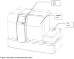
- a key driver is to keep the instrument simple.
- the instrument utilises an X-axis to move embryo pods (pods) from the loading area to the various positions within the instrument such as the dispense position or sealing position.
- the other functions move toward a gantry carriage in the Z-direction.
- embodiments of the invention provide a controlled volume channel which comprises a divot for retaining and/or positioning the embryo for processing.
- the divot is provided with a controlled divot volume, preferably in the range of about 0.04 ⁇ l to about 0.30 ⁇ l, which will be sufficient to accommodate at least a modicum or limited amount of solution in the embryo can be disposed. This serves to prevent embryos from drying. It also controls the carryover of previous solutions throughout processing.
- the divot assists with initial positioning of the embryo and provides for retention of the embryo during fluid exchange.
- the channel comprises walls of a thickness in the range of about 0.01mm to about 0.90mm and preferably of about 0.08mm for enabling rapid heat transfer to occur within the pod.
- a central function of the instrument is to complete the vitrification preparation process, and potentially also to facilitate the vitrification of the embryo.
- the instrument may also complete other functions such as maintaining the pod and solution temperatures throughout the process.
- the instrument in preferred embodiments, will perform accurate fluid exchange with the pod. Nominally this would be via standard OEM pipette tips.
- the instrument also seals the pod so that the system becomes a 'closed' system in regard to possible LN 2 contamination.
- a typical instrument preparation process involves a user performing the following steps:
- the typical Instrument unloading process involves the steps of:
- Logged data can be accessed via a SD card, or its equivalent, that may capture relevant information to assess correct processing at a later date when investigating possible causes of embryo warm and viability results. It is envisaged that service personnel will be able to connect to the instrument via an external connection and PC. This will most likely be via RS232 or RS485 interfaces and there may be limited debug functionality made available via a GUI as would be appreciated by the person skilled in the art.
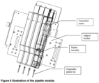
- the automated instrument employs a single X-axis to move an Operating Tray accommodating the embryos between a Solution Exchange Robot, a Lid Transfer Robot and Heat Sealers.
- the X-axis moves the Operating Tray to the location required for each of the functions to be performed with independent Z-direction movement only.
- Solution exchange is an important consideration and has been contemplated as follows. To equilibrate the embryos, the instrument needs to dispense accurately into the pod and also remove solution.
- the Solution Exchange system is provided to allow dispense tips to be positioned correctly in each of up to four pod consumables and to perform the fluid exchanges necessary for the equilibration of the embryos prior to vitrification.
- Fluid dispense velocities are considered an important factor in the present invention and preferred embodiments provide an instrument with the ability to have variable dispense and aspiration velocities to accommodate oocytes and a range of embryo types. This functionality of variable dispense velocities correlates with variable equilibration protocols to provide for controllable equilibration sequences.
- the system may use features on the pods to guide the tip to correct placement.
- An anticipated typical workflow for the automated vitrification is
- the software can control the fluid exchange to gradually increase the concentration of the vitrification media, which in turn will decrease the osmotic shock to the embryo and increase cryopreservation quality as seen by the graph below
- the comparative graph below contrasting the automated and manual means indicates the concentration increase of the cryoprotectants.
- the instrument To perform the solution exchange steps, the instrument has been adapted to pick up tips and after the last solution exchange is performed, it will eject the tips.
- the automated system implements a bent stainless steel profile that engages the pipettes above the tip so that a vertically upwards move by the pipette axis would disengage the tips into a container below.
- This form of removal performs reliably.
- the usability of tip removal should be carefully considered to ensure it is user friendly and safe such that the system makes it not easy for a user to come into contact with the contaminated tips or solutions.
- a preferred embodiment provides transfer of a lid and heat sealing of the lid to a pod to prevent LN 2 contacting the embryo or vitrification fluid during vitrification and storage.
- Figure 7 shows a heat sealing system on a preferred form of instrument in accordance with the present invention comprising a single axis, for combined lid transfer and heat sealing
- Heat-sealing is commonly performed, both with existing foil materials and heat-sealing a polymer straw.
- suction cups for lid pickup were positioned inside a heated sealing head.
- the Instrument is adapted to transfer a lid from the position it is loaded in, onto the pod and this may be performed by individual suction cups and a vacuum source.
- the sealing of the Lid may be provided by applying pressure of about 5-8N at a temperature of nominally about 140-175°C for approximately 2-3 seconds. Testing has shown it can be beneficial for the purposes of maintaining a stable embryo temperature to apply and use a higher temperature for less time. Conversely, for surface treated and sterilised pods a lower temperature based on seal integrity testing may be required. The optimal temperature is in the range of about 140°C to about 155°C.
- a typical expected workflow for the Consumable Sealing is as follows:
- the embryo viability is sensitive to temperature, especially in VS4 solution. It is considered, the temperature of the embryo should not rise above 37.5°C. In certain embodiments the temperature of the embryos, preferably should not rise by more than about 5°C during the 10s period after sealing. These two limitations should be carefully considered as they may strongly affect design of the instrument and workflow.
- Alignment of the heat seal head to the pods has been seen in preferred embodiments to affect the seal consistency. This has been catered for in design so that a consistent and even seal is created, even in the event of slight misalignment in the loading of the pods or Cassette.
- the instrument should detect when a lid is not present at the instant before heat sealing and not contact that pod. This will ensure that the heat sealer does not get contaminated with melted polypropylene from the pod.
- a Peltier module or any other equivalent thermoelectric heat transfer device is employed in embodiments to maintain the embryos at the target protocol temperature during the equilibration steps on the Instrument.
- the Peltier may preferably serve to operatively associate the pod by way of one or a combination of locating, providing thermal contact and reliably connecting, wherein locating and releasing the cassette from the Peltier may be assisted by arrangement of magnets. These functions may be able to be applied to other consumables.
- the pods and media are maintained at a particular temperature throughout the protocol. As the ambient temperature in the labs may be above the minimum protocol temperature, cooling must be allowed for as well. The other motivation for cooling is to allow a shorter time between protocols of different temperatures, rather than relying on ambient thermal diffusion.
- the Transverse Carriage comprises an aluminium stage mounted to the X-Axis Robot, using a Peltier and a temperature sensor to maintain accurate temperature.
- the pods and Media Vials have good thermal contact with the Peltier Module's interface plate, or as good a thermal contact as can be practically achieved. Accordingly, the following is considered and provided:
- a transverse axis robot means is provided to move the Peltier Module to each X position as required in the protocol. This may be driven by the layout decision.
- the Instrument may therefore have one transverse axis that moves a carriage to each x-location as required, for example, to move the heat sealers in line with the lids, or place the end of the tip into the pod to dispense.
- the transverse axis means provides positional accuracy within about 0.1mm to cater for the tolerance stack between the built Instrument, a loaded tip with its 1.016mm runout, and any tolerance due to the fit between pods and the Carriage. This is estimated based on the above runout of tips and a reasonable tolerance stack-up due to build (in) accuracies.
- the means is capable of moving at estimated velocities up to approximately 100mm/s. Either step loss should reliably not occur or step loss detection should be implemented such that the loss of steps does not cause a possible failure of any instrument functions.
- the Transverse Axis and Carriage may have many interfaces, some of which are discussed in more detail below. A critical interface is between the Transverse Axis and the Z-Axis (or Gantry as it may be referred to).
- the core technology depends on positional accuracies that are driven by both the Transverse and Z axis. Accordingly, the Transverse Axis is mounted securely in the chassis of the instrument. The tolerance on this can be greater than to the Z-axis provided that the consumable detection system can handle it.
- components of the Transverse Axis are preferably designed to be replaceable either directly in the Instrument, or by swapping out a sub-assembly.
- a Z-axis robot means or gantry is provided in preferred embodiments to move the Solution Exchange and the Consumable Sealing systems in the Z-direction, to each height as required by the protocol. It is also utilised to push on the Pipette Tips to the Pipettes, and also remove the Tips from the Pipettes.
- the Z-axis utilises a stepper motor to drive a lead-screw/ball-screw mounted carriage. Additional support and constraint is provided to the carriage via two linear bearings mounted on the Solution Exchange side of the Gantry plate. This is because tolerances are more critical for the Tip to pod interaction compared to the heat sealing.
- tips were removed from Dispense Pumps using a tip removing feature attached to the Heated Carriage.
- the tips By moving the Dispense Pumps down and then the Transverse Carriage across, the tips can be held in place by a Tip Remover whilst driving a Dispense Axis robot up to pull the disposable tips off the Dispense Pump adaptors.
- the space around the Transverse Carriage and the user interaction may be simplified by adding a separate simple axis to move a 'tip stripper1 into place allowing tips to be stripped back into their original holder rather than requiring a separate bin.
- LN2 liquid nitrogen
- An example LN2 storage vessel for the Instrument is represented in figure 9 and it is noted that a handle may be added. Accommodation for LN2 is within the Instrument footprint so that for manual vitrification, the LN2 bath is conveniently located for quick immersion of the Cassette when the protocol finishes.
- the transfer of the Cassette to LN 2 for vitrification is automated.
- the LN 2 capabilities detect the presence and level of the LN 2 .
- the Instrument preferably also transfers the Cassette from the Transverse Carriage to the LN 2 bath. This transfer may include agitation as determined by testing.
- the Instrument is adapted to detect that there is enough LN 2 in the bath for the Cassette to be transferred into for embryo vitrification at the end of the automated equilibration steps. For manual vitrification, it will be up to the user to ultimately ensure that they have enough LN 2 in a container to vitrify but the instrument should be capable of providing feedback of empty/too low, enough, etc. For automated vitrification on board, the LN 2 level detection/check may be part of the critical performance as if there is not enough LN 2 when the instrument transfers the Cassette, the embryos will not survive. In either case, the Instrument is preferably adapted to perform the check at the beginning of the protocol, preferably when it checks the presence of consumables.
- the LN 2 bath is formed to be large enough and have controlled evaporation so that within the operating environment range of the Instrument (18°C to 27°C), the LN 2 will not evaporate below the minimum required level within about 30 minutes.
- the LN 2 should be isolated from the loading area such that an Operator does not pass their hand through LN 2 vapours and so that it is not easily possible to cause LN 2 vapours to either pass over any loaded consumables or to disturb the temperature control of the Transverse Carriage.
- Any removable container with LN 2 will preferably have a handle for OH&S reasons.
- the material chosen is preferably capable of withstanding the repeated thermal shock of being at ambient temperature and having LN 2 poured into it.
- a preferred product is manufactured from HDPE.
- All subsystem assemblies of the instrumentation mount to a chassis.
- the subsystems are preferably located precisely as any misalignments may add to create misalignment at the pod. This could have severe consequences such as incorrect positioning of the tip in the pod or failure to align the lids on the pods.
- a preferred embodiment has incorporated a sub-module that isolates all of the systems involved in operations of high accuracy. These critical operations involve interactions between items on the Transverse Carriage and either of the Solution Exchange or Consumable Sealing systems.
- a combined 'gantry' and transverse module are provided that can be assembled into the main chassis.
- the main chassis can then have 'standard' tolerances for general fit of components.
- the instrument dimensions and weight correspond to maximum dimensions of about 750mm wide x about 700mm deep x about 600mm high with a maximum weight of about 45kg.
- a colour touchscreen display is used for user control of the Instrument, for example, an LCD touchscreen.
- Figure 10 shows example screenshots of a GUI in a preferred embodiment. Whilst other display options may provide the functionality, it is considered that current market expectations demand a colour touchscreen to control an instrument of this level of technology and a GUI embodies such a user interface.
- the GUI comprises 5.7" display whereas other embodiments involve different screen sizes such as a 4.3" display.
- Resistive and capacitive touchscreens are considered suitable.
- a resistive touchscreen is provided in a preferred embodiment on the basis of its competitive and development time. Ordinarily, no alcohol or aromatics are allowed in clinical laboratories and only mild soap and water are typically allowed for cleaning so there is no specific requirement for a glass cover over the screen but this may be provided.
- Logging of data may occur in two forms. One level of logging is such that it will only be accessed by service personnel and will log detailed instrument data for each protocol run. The other level of logging will log data relevant for confirming details of the protocol used for an embryo warmed at a later date, included high-level instrument function confirmation (eg temperature of Carriage). These "logs" may be tracked by a unique identifier, and time and date stamp.
- the instrument in preferred embodiments is designed in accordance with an appropriate standard such as for example, 'ANSI/AAMI/IEC 62366:2007 Medical devices - Application of usability engineering to medical devices' using guidance from the standard, 'ANSI/AAMI HE75:2009 Human factors engineering - Design of medical devices'.
- an appropriate standard such as for example, 'ANSI/AAMI/IEC 62366:2007 Medical devices - Application of usability engineering to medical devices' using guidance from the standard, 'ANSI/AAMI HE75:2009 Human factors engineering - Design of medical devices'.
- the instrument will follow the international standard, I EC 61010 or the equivalent as dictated by regulatory requirements.
- a hazard analysis may be conducted to identify areas requiring attention to increase safety.
- Peltiers may fail or bearings or guides may wear, leading to potential failure. Where practical, these have been designed to be relatively easily replaced.
- the pod allows for automated fluid exchange and vitrification of an embryo. Embryos are typically approximately about 50pm-300um in diameter although during the process, they may collapse and re-expand so at times they are much smaller than this.
- the vitrification process requires that the embryo be exposed to several solutions for specific durations and at specific temperatures to replace water in and around the embryo cell(s) with cryoprotectants to eliminate or reduce the damage due to cryopreservation and, as noted above, typically damage is due to ice crystals.
- the pod device prevents the embryo being drawn up with aspirated fluid but allows fluid exchange to take place and allow for high heat transfer rates in a 'closed' system.
- a 'closed' system in this case refers to a vitrification system that prevents direct contact between LN2 and the embryo.
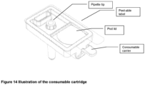
- Figures 15 to 18 illustrate a typical pod in accordance with preferred embodiments of the present invention. Essentially the pod in these embodiments comprises three components, namely, a carrier for support, a lid and a channel. The channel includes a divot for accommodating the specimen embryo, which is described in published PCT specification No. WO 2011/146998 .
- the preferred pod design has the following features:
- four pods are stored in a cassette, which serves also as the final storage container to be placed in LN2 tanks, without reducing current storage capacity in the LN2 or LN2 liquid or vapour storage tanks.
- the pods are also adapted to fit onto the Transverse Carriage well so that there is adequate heat transfer to maintain good temperature control during processing.
- the pod channel is preferably manufactured separately and it could be combined into a single unitary part.
- the pods are adapted to fit onto the Transverse Carriage well so that there is adequate heat transfer to maintain good temperature control during processing.
- the channel is wettable by way of surface treatment or other modifications. Many surface treatments were tested including but not limited to flame treatment, chemical, corona and plasma treatment.
- the pod is preferably treated by plasma treatment. Optical clarity of the Channel is relevant to its usability.
- the Channel is adapted to seal to the Carrier to be impermeable to LN2.
- the maximum volume of fluid that can be added to a pod is about 55
- the Carrier is the part of the pod that will carry the label and provide the means to handle the Channel. In this respect it provides space for LN2, proof labelling and an appropriate surface.
- the carrier attaches to the Cassette at room temperature down to about -196°C and may be removable in the same temperature range.
- the Lid will contain Aluminium/polypropylene laminated heat seal as abovementioned, and will be sealed to the pod Channel and Carrier.
- the Lid is designed such that it is easily removed upon warming for prompt addition of the re-equilibration solutions.
- a Cassette is the part that will hold any suitable number, preferably up to four, pods at a time and an example is shown in figure 12 . It is a replacement for the 'canes' used in current systems to store multiple vitrification devices such as hooks, Cryotop ® , straws etc from the same patient in the LN2 or vapour storage tanks.
- the cassette preferably includes a handle that allows a user to hold the Cassette to vitrify the embryos in the pods.
- the Cassette is also equipped to have adequate area for a barcode and other ID. In one form the cassette is adapted for some form of ID to be readable from above a Canister full of Cassettes, as shown in figure 12 .
- the cassette preferably has the following features:
- the pods are adapted for easy insertion into the Cassette at room temperature. When loaded onto the instrument, the pods are able to move to locate to the Carriage rather than being restricted by the Cassette. Pods are removable under LN2 or vapours and do not readily fall out of Cassette. To enable a consistent removal of the pod from the cassette, repeatable force is applied by magnets appropriately positioned which are adapted to exercise magnetic field strength of given magnitude upon the ferrous metal residing in the pod. To this end the magnets are preferably positioned in distributed locations within the cassettes.
- the cassette interfaces with the Instrument via the Carriage and interfaces with a Canister in storage. Further, the cassette is easily removable from the Canister whilst keeping all embryos within either LN2 or vapour.
- the pod may be designed with enough buoyancy to float in the case it was to be separated from the cassette in the LN2 tank.
- a consumable tray is provided for vials of vitrification solutions, waste, and pipette tips. It sits flat on a bench or hot plate and allows heat transfer through to the pod and solutions. It is also easily handled and easily and accurately loaded into position on the Heated Carriage.
- the pods are located in the Consumable Tray by the fit of the Cassette and also channel features on the Consumable Tray that aid heat transfer to the solutions within the pod.
- the vials are close-fitting into the Consumable Tray for both location and heat transfer reasons.
- the Consumable Tray is also adapted to allow the consumables to pass under the various stations at a low clearance height to reduce the Z-axis travels for each station.
- the tips however are preferably much higher than the other components. Given this requirement and the requirement to rest flat on a bench, the Tray has been designed with a floating tip holder so that it can rest high when on a bench or hot plate, and rest low within a cut-out when loaded on the instrument. Tips may be loaded by driving the Dispense Axis down into the tips against their holder in the Consumable Tray. The force to pick up tips is about 60-100N (6-10kg) vertically down.
- the tray is adapted to fit to pitch of about 28.5mm and is adapted to positively engage into the instrument with and overall maximum height of about 60mm.
- a media cartridge may be provided with features including the following. It is adapted to hold at least two fluid vials in a removable and sterile fashion.
- the media cartridge is adapted to fit to pitch of about 28.5mm. It can maximise heat exchange to the media vials and is adapted for positive engagement of the media vials.
- Media vials may be provided which contain a minimum of about 100 ⁇ L solution and are determined by what is suitable for media production and shelf-life.
- a tip cartridge is provided with the following features.
- the force required to pick up tips is about 60-100N (6-10kg) vertically down.
- the tip cartridge holds at least one clear waste vial for post protocol embryo checking and holds at least one sterile pipette tips. It holds at least one sterile heat sealable Lid and fits to a pitch of about 28.5mm. It minimises storage volume for dry components. It also provides for tip removal back into the consumable/disposable for disposal.
- a dispense tip is provided and an OEM tip is preferable.
- the 10 ⁇ L filtered Axygen TM TF300 tip has been used.
- the tip has a fine distal end such that it can fit inside the pod channel, allowing for tolerances of the pod, tip and instrument.
- the tip is adapted to hold a minimum of about 10 ⁇ L and it should be filtered. It is also preferable that the dispense tip is adapted for interaction with pipette tips.
- canisters are provided for use as containers to hold a number of Cassettes in storage tanks or dewars.
- Current systems use canisters to hold Canes, which then hold a number of straws, or other vitrification devices.
- the exemplary canisters are designed for the following systems: LN 2 storage tanks; LN 2 vapour phase storage tanks, dry shippers and Dewar storage systems.
- Dewar Storage there is capacity for 16 small canes @ 3 - 6 embryos each, or alternatively 4 large canes @ 7 embryos each.
- Canister capacity is equivalent to about 20 patients ie, 76 embryos which equates to total capacity.
- tank storage there is capacity for 16 small canes @ 3 embryos each, or alternatively 10 large canes @ 7 embryos each.
- Canister capacity is equivalent to about 26 patients ie, 118 embryos.
- 2-Canister stack there is capacity equivalent to about 52 patients ie, 236 embryos.
- a communication device is described that may be used in a communication system, unless the context otherwise requires, and should not be construed to limit the present invention to any particular communication device type.
- a communication device may include, without limitation, a bridge, router, bridge-router (router), switch, node, or other communication device, which may or may not be secure.
- a processor e.g., a microprocessor, microcontroller, digital signal processor, or general purpose computer and for that matter, any commercial processor may be used to implement the embodiments of the disclosure either as a single processor, serial or parallel set of processors in the system and, as such, examples of commercial processors include, but are not limited to Merced TM , Pentium TM , Pentium II TM , Xeon TM , Celeron TM , Pentium Pro TM , Efficeon TM , Athlon TM , AMD TM and the like), programmable logic for use with a programmable logic device (e.g., a Field Programmable Gate Array (FPGA) or other PLD), discrete components, integrated circuitry (e.g., an Application Specific Integrated Circuit (ASIC)), or any other means including any combination thereof.
- a programmable logic device e.g., a Field Programmable Gate Array (FPGA) or other PLD
- FPGA
- predominantly all of the communication between users and the server is implemented as a set of computer program instructions that is converted into a computer executable form, stored as such in a computer readable medium, and executed by a microprocessor under the control of an operating system.
- Computer program logic implementing all or part of the functionality where described herein may be embodied in various forms, including a source code form, a computer executable form, and various intermediate forms (e.g., forms generated by an assembler, compiler, linker, or locator).
- Source code may include a series of computer program instructions implemented in any of various programming languages (e.g., an object code, an assembly language, or a high-level language such as Fortran, C, C++, JAVA, or HTML.
- the source code may define and use various data structures and communication messages.
- the source code may be in a computer executable form (e.g., via an interpreter), or the source code may be converted (e.g., via a translator, assembler, or compiler) into a computer executable form.
- the computer program may be fixed in any form (e.g., source code form, computer executable form, or an intermediate form) either permanently or transitorily in a tangible storage medium, such as a semiconductor memory device (e.g, a RAM, ROM, PROM, EEPROM, or Flash-Programmable RAM), a magnetic memory device (e.g., a diskette or fixed disk), an optical memory device (e.g., a CD-ROM or DVD-ROM), a PC card (e.g., PCMCIA card), or other memory device.
- a semiconductor memory device e.g, a RAM, ROM, PROM, EEPROM, or Flash-Programmable RAM
- a magnetic memory device e.g., a diskette or fixed disk
- an optical memory device e.g., a CD-ROM or DVD-ROM
- PC card e.g., PCMCIA card
- the computer program may be fixed in any form in a signal that is transmittable to a computer using any of various communication technologies, including, but in no way limited to, analog technologies, digital technologies, optical technologies, wireless technologies (e.g., Bluetooth), networking technologies, and inter-networking technologies.
- the computer program may be distributed in any form as a removable storage medium with accompanying printed or electronic documentation (e.g., shrink wrapped software), preloaded with a computer system (e.g., on system ROM or fixed disk), or distributed from a server or electronic bulletin board over the communication system (e.g., the Internet or World Wide Web).
- Hardware logic including programmable logic for use with a programmable logic device
- implementing all or part of the functionality where described herein may be designed using traditional manual methods, or may be designed, captured, simulated, or documented electronically using various tools, such as Computer Aided Design (CAD), a hardware description language (e.g., VHDL or AHDL), or a PLD programming language (e.g., PALASM, ABEL, or CUPL).
- Hardware logic may also be incorporated into display screens for implementing embodiments of the invention and which may be segmented display screens, analogue display screens, digital display screens, CRTs, LED screens, Plasma screens, liquid crystal diode screen, and the like.
- Programmable logic may be fixed either permanently or transitorily in a tangible storage medium, such as a semiconductor memory device (e.g., a RAM, ROM, PROM, EEPROM, or Flash-Programmable RAM), a magnetic memory device (e.g., a diskette or fixed disk), an optical memory device (e.g., a CD-ROM or DVD-ROM), or other memory device.
- a semiconductor memory device e.g., a RAM, ROM, PROM, EEPROM, or Flash-Programmable RAM
- a magnetic memory device e.g., a diskette or fixed disk
- an optical memory device e.g., a CD-ROM or DVD-ROM
- the programmable logic may be fixed in a signal that is transmittable to a computer using any of various communication technologies, including, but in no way limited to, analog technologies, digital technologies, optical technologies, wireless technologies (e.g., Bluetooth), networking technologies, and internetworking technologies.
- the programmable logic may be distributed as a removable storage medium with accompanying printed or electronic documentation (e.g., shrink wrapped software), preloaded with a computer system (e.g., on system ROM or fixed disk), or distributed from a server or electronic bulletin board over the communication system (e.g., the Internet or World Wide Web).
- printed or electronic documentation e.g., shrink wrapped software
- a computer system e.g., on system ROM or fixed disk
- server or electronic bulletin board e.g., the Internet or World Wide Web
Claims (15)
- Vorrichtung zur Mikromanipulation und Kryokonservierung von biologischem Material, wobei das biologische Material einen Embryo oder eine Eizelle umfasst und die Vorrichtung ein Gefäß mit einem Reservoir umfasst, wobei das Gefäß einen Kanal aufweist, der in einem Abschnitt des Reservoirs gebildet ist, wobei der Kanal eine Zwischenverengung umfasst, die so dimensioniert ist, dass sie dem Durchgang des biologischen Materials widersteht, aber den Durchgang von flüssigen Behandlungslösungen ermöglicht, wobei der Kanal Wände mit einer Stärke im Bereich von etwa 0,01 mm bis etwa 0,90 mm aufweist, wobei die Vorrichtung eine zweiteilige Konstruktion umfasst, die Polymermaterial umfasst, wobei zwei Abschnitte der Vorrichtung dafür ausgelegt sind, mit einem sekundären Material zwischen den beiden Abschnitten vor einem Verglasungsprozessschritt heißversiegelt zu werden, und wobei das Sekundärmaterial eine Ablösung der zweiteiligen Konstruktion ermöglicht.
- Vorrichtung nach Anspruch 1, wobei die beiden Abschnitte aus Polypropylen bestehen und das Sekundärmaterial ein Laminat ist, das dafür ausgelegt ist, das Eindringen von LN2 in die Vorrichtung zu verhindern.
- Vorrichtung nach Anspruch 1 oder 2, wobei der Kanal ein Kanal mit kontrolliertem Volumen ist, der eine Vertiefung zum Halten und/oder Positionieren eines Embryos für die Bearbeitung umfasst.
- Vorrichtung nach Anspruch 1 oder 2, wobei der Kanal ferner eine Vertiefung mit einem Volumen von etwa 0,04 µl bis etwa 0,30 µl umfasst, die zum Zurückhalten und/oder Positionieren eines Embryos darin in zumindest einem geringen Teil der Lösung ausgelegt ist.
- Vorrichtung nach einem der Ansprüche 1 bis 4, wobei die Oberfläche des Kanals, die dem biologischen Material und den flüssigen Behandlungslösungen ausgesetzt ist, oberflächenbehandelt ist, damit die Flüssigkeit die Oberfläche des Kanals benetzen und sich darauf ausbreiten kann.
- Vorrichtung nach einem der Ansprüche 1 bis 5, wobei die Wandstärke im Bereich von etwa 0,01 mm bis etwa 0,12 mm liegt.
- Vorrichtung nach einem der Ansprüche 1 bis 5, wobei die Wandstärke im Bereich von etwa 0,08 mm bis etwa 0,12 mm liegt.
- System, das Folgendes umfasst:die Vorrichtung nach einem der Ansprüche 1 bis 7; undeine Kombination von unabhängigen einachsigen Roboterarmen, wobei jeder einachsige Roboterarm an einer statischen Anordnung befestigt ist, und wobei die Kombination von Roboterarmen ein globales Koordinatensystem für die Bewegung der Vorrichtung in mindestens zwei Freiheitsgraden bereitstellt,wobei das System dafür ausgelegt ist, die Vorrichtung durch mindestens zwei der folgenden Prozessschritte zu führen:Laden des Embryos;Äquilibrierung;Heißsiegelung;Verglasung.
- System nach Anspruch 8, wobei das System dafür konfiguriert ist, eine einzige Achse zu verwenden, um ein Arbeitstablett, das die Vorrichtung aufnimmt, zwischen einem Lösungsaustauschroboter, einem Deckeltransferroboter und Heißsiegelvorrichtungen zu bewegen.
- Verfahren zur Mikromanipulation und Kryokonservierung eines Embryos, der in In-vitro-Fertilisationsverfahren verwendet werden soll, unter Verwendung einer Vorrichtung nach einem der Ansprüche 1 bis 7, wobei das Verfahren folgende Schritte umfasst::Laden des Embryos in die Vorrichtung in einer Pufferlösung;Ersetzen der Pufferlösung durch eine Äquilibrierungslösung mit einer vorbestimmten Fließgeschwindigkeit;Äquilibrieren des geladenen Embryos in der Äquilibrierungslösung für eine vorbestimmte Äquilibrierungszeitspanne;Ersetzen der Äquilibrierungslösung durch eine Verglasungslösung mit einer vorbestimmten Fließgeschwindigkeit;Heißsiegeln der Vorrichtung;Eintauchen der Vorrichtung in ein flüssiges Kühlbad.
- Verfahren nach Anspruch 10, wobei der Schritt des Heißversiegelns mit einer Vorbedingung des optischen Nachweises des Vorhandenseins eines Verbrauchsmaterials zur Aufnahme des biologischen Materials, das in die Vorrichtung geladen wird, durchgeführt wird.
- Verfahren nach Anspruch 10 oder 11, wobei eine Flüssigkeitsabgabe- und Ansauggeschwindigkeit zum Ersetzen der Lösungen in einem Bereich von etwa 0,01 µl/s bis etwa 5 µl/s gesteuert wird.
- System, das zur Mikromanipulation von biologischem Material unter Verwendung einer Vorrichtung nach einem der Ansprüche 1 bis 7 ausgelegt ist, wobei das Mikromanipulationssystem Folgendes umfasst:ein Prozessormittel, das dafür ausgelegt ist, gemäß einem vorbestimmten Befehlssatz zu arbeiten,wobei das Mikromanipulationssystem in Verbindung mit dem Befehlssatz dafür ausgelegt ist, den Zeitablauf, die Temperatur, die Abgabemengen und die Fließgeschwindigkeit zu steuern, die bei der Durchführung der Verfahrensschritte nach einem der Ansprüche 10 bis 12 beteiligt sind.
- Mikromanipulationssystem nach Anspruch 13, wobei der vorbestimmte Befehlssatz eine Computersoftware umfasst, die dafür ausgelegt ist, einen Flüssigkeitsaustausch zu steuern, um eine allmähliche Erhöhung der Konzentration der Verglasungslösung zu ermöglichen, um einen osmotischen Schock für den Embryo zu verringern und die Qualität der Kryokonservierung zu erhöhen.
- Computerprogrammprodukt, das Anweisungen umfasst, die: wenn sie auf einem Computerprozessor ausgeführt werden, der zum Betreiben des Mikromanipulationssystems nach Anspruch 13 oder 14 konfiguriert ist, das Mikromanipulationssystem veranlassen, die Verfahrensschritte nach einem der Ansprüche 10 bis 12 auszuführen, wobei die Anweisungen dafür ausgelegt sind, den Flüssigkeitsaustausch in der Vorrichtung zu steuern, um eine allmähliche Erhöhung der Konzentration der Verglasungslösung zu ermöglichen, um einen osmotischen Schock für den Embryo zu verringern und die Qualität der Kryokonservierung zu erhöhen.
Applications Claiming Priority (2)
| Application Number | Priority Date | Filing Date | Title |
|---|---|---|---|
| AU2013900039A AU2013900039A0 (en) | 2013-01-07 | Method, System and Apparatus for Improved Micromanipulation and Storage | |
| PCT/AU2014/000005 WO2014106286A1 (en) | 2013-01-07 | 2014-01-07 | Method, system and apparatus for improved micromanipulation and storage |
Publications (4)
| Publication Number | Publication Date |
|---|---|
| EP2941124A1 EP2941124A1 (de) | 2015-11-11 |
| EP2941124A4 EP2941124A4 (de) | 2016-08-10 |
| EP2941124B1 true EP2941124B1 (de) | 2023-06-07 |
| EP2941124C0 EP2941124C0 (de) | 2023-06-07 |
Family
ID=51062103
Family Applications (1)
| Application Number | Title | Priority Date | Filing Date |
|---|---|---|---|
| EP14735286.8A Active EP2941124B1 (de) | 2013-01-07 | 2014-01-07 | Verfahren, system und vorrichtung für verbesserte mikromanipulation und lagerung |
Country Status (12)
| Country | Link |
|---|---|
| US (1) | US9826733B2 (de) |
| EP (1) | EP2941124B1 (de) |
| JP (1) | JP6535284B2 (de) |
| CN (1) | CN105101790B (de) |
| AU (1) | AU2014204411B2 (de) |
| CA (1) | CA2897219C (de) |
| ES (1) | ES2953310T3 (de) |
| HK (1) | HK1217876A1 (de) |
| HU (1) | HUE063344T2 (de) |
| IL (1) | IL239808A (de) |
| PL (1) | PL2941124T3 (de) |
| WO (1) | WO2014106286A1 (de) |
Families Citing this family (10)
| Publication number | Priority date | Publication date | Assignee | Title |
|---|---|---|---|---|
| WO2017122210A1 (en) * | 2016-01-13 | 2017-07-20 | Fertilesafe Ltd. | Automatic devices configured to perform a cryoprocedure on at least one biological sample carried by one or more carriers |
| US11617365B2 (en) | 2015-10-13 | 2023-04-04 | Fertilesafe Ltd. | Devices and methods for preparation of a biological sample for a cryoprocedure |
| EP3416483A4 (de) | 2016-02-19 | 2019-09-11 | Regents of the University of Minnesota | Kryoprotektionszusammensetzungen und -verfahren |
| WO2017184721A1 (en) | 2016-04-19 | 2017-10-26 | Regents Of The University Of Minnesota | Cryopreservation compositions and methods involving nanowarming |
| DK179163B9 (en) * | 2016-07-01 | 2018-04-03 | Esco Medical Uab | An apparatus for the combined incubation and vitrification of a biological material |
| CN108913532B (zh) * | 2018-07-16 | 2021-10-29 | 东北大学 | 面向工业恶臭污泥的生物降解细菌分离培养仪及使用方法 |
| WO2020023222A1 (en) * | 2018-07-23 | 2020-01-30 | Regents Of The University Of Minnesota | Systems and methods for cryopreservation of biomaterials |
| US11116206B2 (en) | 2018-10-01 | 2021-09-14 | Cook Medical Technologies Llc | Cryocontainer |
| JP2022515526A (ja) | 2018-12-28 | 2022-02-18 | オーバーチュア ライフ,インコーポレイテッド | 凍結保存中の卵母細胞および胚のための凍結保存装置 |
| WO2022032094A1 (en) | 2020-08-07 | 2022-02-10 | Overture Life, Inc. | Microfluidic devices and methods for delivering solutions to biological material |
Family Cites Families (32)
| Publication number | Priority date | Publication date | Assignee | Title |
|---|---|---|---|---|
| US6000603A (en) | 1997-05-23 | 1999-12-14 | 3M Innovative Properties Company | Patterned array of metal balls and methods of making |
| US8709153B2 (en) | 1999-06-28 | 2014-04-29 | California Institute Of Technology | Microfludic protein crystallography techniques |
| US7459022B2 (en) | 2001-04-06 | 2008-12-02 | California Institute Of Technology | Microfluidic protein crystallography |
| US6929030B2 (en) | 1999-06-28 | 2005-08-16 | California Institute Of Technology | Microfabricated elastomeric valve and pump systems |
| US8052792B2 (en) | 2001-04-06 | 2011-11-08 | California Institute Of Technology | Microfluidic protein crystallography techniques |
| US7217321B2 (en) | 2001-04-06 | 2007-05-15 | California Institute Of Technology | Microfluidic protein crystallography techniques |
| US7306672B2 (en) | 2001-04-06 | 2007-12-11 | California Institute Of Technology | Microfluidic free interface diffusion techniques |
| US7144616B1 (en) | 1999-06-28 | 2006-12-05 | California Institute Of Technology | Microfabricated elastomeric valve and pump systems |
| US20080277007A1 (en) | 1999-06-28 | 2008-11-13 | California Institute Of Technology | Microfabricated elastomeric valve and pump systems |
| US6899137B2 (en) | 1999-06-28 | 2005-05-31 | California Institute Of Technology | Microfabricated elastomeric valve and pump systems |
| US7195670B2 (en) | 2000-06-27 | 2007-03-27 | California Institute Of Technology | High throughput screening of crystallization of materials |
| EP1065378B1 (de) | 1999-06-28 | 2002-04-03 | California Institute of Technology | Elastomerische mikropumpen- und mikroventilsysteme |
| US7501245B2 (en) | 1999-06-28 | 2009-03-10 | Helicos Biosciences Corp. | Methods and apparatuses for analyzing polynucleotide sequences |
| US8550119B2 (en) | 1999-06-28 | 2013-10-08 | California Institute Of Technology | Microfabricated elastomeric valve and pump systems |
| US7052545B2 (en) | 2001-04-06 | 2006-05-30 | California Institute Of Technology | High throughput screening of crystallization of materials |
| US6818395B1 (en) | 1999-06-28 | 2004-11-16 | California Institute Of Technology | Methods and apparatus for analyzing polynucleotide sequences |
| US7244402B2 (en) | 2001-04-06 | 2007-07-17 | California Institute Of Technology | Microfluidic protein crystallography |
| US7670429B2 (en) | 2001-04-05 | 2010-03-02 | The California Institute Of Technology | High throughput screening of crystallization of materials |
| AU2003901871A0 (en) * | 2003-03-31 | 2003-05-08 | Vision Biosystems Limited | A method and apparatus for fluid dispensation, preparation and dilation |
| CA2492064C (en) * | 2002-06-20 | 2016-03-15 | Vision Biosystems Limited | Biological reaction apparatus with draining mechanism |
| JP4355186B2 (ja) * | 2003-04-15 | 2009-10-28 | 株式会社北里サプライ | 卵凍結保存用具 |
| US20060172408A1 (en) | 2003-12-01 | 2006-08-03 | Quake Steven R | Device for immobilizing chemical and biochemical species and methods of using same |
| JP4710468B2 (ja) | 2005-07-28 | 2011-06-29 | セイコーエプソン株式会社 | 印刷要求装置、印刷システムおよび印刷要求方法 |
| US20070249038A1 (en) * | 2006-04-21 | 2007-10-25 | Andrea Adamo | Microfluidic device for single cell targeted operations |
| US20090123992A1 (en) * | 2007-11-12 | 2009-05-14 | Milton Chin | Shape-Shifting Vitrification Device |
| AU2009219096A1 (en) | 2008-02-25 | 2009-09-03 | Genea Limited | Cryopreservation of biological cells and tissues |
| WO2010011766A1 (en) | 2008-07-23 | 2010-01-28 | Mariposa Biotechnology, Inc. | Automated system for cryopreservation of oocytes, embryos, or blastocysts |
| US8656985B2 (en) | 2008-09-30 | 2014-02-25 | International Business Machines Corporation | Rackmount rear door heat exchanger |
| WO2011146998A1 (en) | 2010-05-28 | 2011-12-01 | Sydney Ivf Limited | Improved micromanipulation and storage apparatus and methods |
| CN101947124B (zh) | 2010-06-25 | 2012-07-04 | 博奥生物有限公司 | 一种集成式微流控芯片装置及其使用方法 |
| JP2012232370A (ja) * | 2011-04-28 | 2012-11-29 | Seiko Epson Corp | ロボットコントローラー、簡易設置型ロボット、及び簡易設置型ロボットの制御方法 |
| CN102835389B (zh) * | 2012-09-11 | 2014-11-05 | 苏州大学 | 玻璃化冷冻自动化操作系统及操作方法 |
-
2014
- 2014-01-07 WO PCT/AU2014/000005 patent/WO2014106286A1/en active Application Filing
- 2014-01-07 HU HUE14735286A patent/HUE063344T2/hu unknown
- 2014-01-07 EP EP14735286.8A patent/EP2941124B1/de active Active
- 2014-01-07 PL PL14735286.8T patent/PL2941124T3/pl unknown
- 2014-01-07 AU AU2014204411A patent/AU2014204411B2/en active Active
- 2014-01-07 US US14/759,419 patent/US9826733B2/en active Active
- 2014-01-07 CA CA2897219A patent/CA2897219C/en active Active
- 2014-01-07 JP JP2015551089A patent/JP6535284B2/ja active Active
- 2014-01-07 ES ES14735286T patent/ES2953310T3/es active Active
- 2014-01-07 CN CN201480011612.9A patent/CN105101790B/zh active Active
-
2015
- 2015-07-06 IL IL239808A patent/IL239808A/en active IP Right Grant
-
2016
- 2016-05-25 HK HK16105953.6A patent/HK1217876A1/zh unknown
Also Published As
| Publication number | Publication date |
|---|---|
| IL239808A0 (en) | 2015-08-31 |
| CN105101790A (zh) | 2015-11-25 |
| EP2941124A1 (de) | 2015-11-11 |
| CA2897219A1 (en) | 2014-07-10 |
| AU2014204411A1 (en) | 2015-08-20 |
| IL239808A (en) | 2017-12-31 |
| PL2941124T3 (pl) | 2023-12-27 |
| EP2941124A4 (de) | 2016-08-10 |
| EP2941124C0 (de) | 2023-06-07 |
| CN105101790B (zh) | 2018-09-21 |
| CA2897219C (en) | 2021-10-19 |
| AU2014204411B2 (en) | 2017-11-02 |
| JP6535284B2 (ja) | 2019-06-26 |
| JP2016508714A (ja) | 2016-03-24 |
| US9826733B2 (en) | 2017-11-28 |
| HUE063344T2 (hu) | 2024-01-28 |
| HK1217876A1 (zh) | 2017-01-27 |
| WO2014106286A1 (en) | 2014-07-10 |
| US20150351381A1 (en) | 2015-12-10 |
| ES2953310T3 (es) | 2023-11-10 |
Similar Documents
| Publication | Publication Date | Title |
|---|---|---|
| EP2941124B1 (de) | Verfahren, system und vorrichtung für verbesserte mikromanipulation und lagerung | |
| JP6114185B2 (ja) | 改良された顕微操作ならびに保管装置および方法 | |
| EP2257155B1 (de) | Kryokonservierung von biologischen zellen und geweben | |
| Liu et al. | Automated vitrification of embryos: A robotics approach | |
| WO2010056755A2 (en) | Microfluidic embryo and gamete culture systems | |
| CN112384809A (zh) | 流体自动采样器和培育器 | |
| US20140335555A1 (en) | Automated vitrification device | |
| AU2018214954B2 (en) | Devices for tissue cryopreservation and recovery | |
| JP2016508714A5 (de) | ||
| ES2783830T3 (es) | Automatización de incubación, procesamiento, recolección y análisis de muestras en una placa multicelda con soporte de muestra de película delgada | |
| EP3263694A1 (de) | Vorrichtung zur kombinierten inkubation und vitrifizierung eines biologischen materials | |
| BRPI0717275A2 (pt) | Método e dispositivo para carregamento de amostra de teste | |
| US20190225923A1 (en) | Apparatus for embryo biopsy | |
| Roy et al. | Chapter 20 gavi-automated vitrification instrument | |
| US20200102528A1 (en) | In vitro fertilization system and components associated therewith | |
| CN110088630B (zh) | 自动运输单元和系统 | |
| US11653644B2 (en) | System for rapid cooling and warming of cells and other biological material | |
| US20220346371A1 (en) | Cryostorage device | |
| WO2023150378A1 (en) | Automated needle-based sample collector for bioreactors | |
| Bolton | “Lost” Embryo in the Laboratory |
Legal Events
| Date | Code | Title | Description |
|---|---|---|---|
| PUAI | Public reference made under article 153(3) epc to a published international application that has entered the european phase |
Free format text: ORIGINAL CODE: 0009012 |
|
| 17P | Request for examination filed |
Effective date: 20150804 |
|
| AK | Designated contracting states |
Kind code of ref document: A1 Designated state(s): AL AT BE BG CH CY CZ DE DK EE ES FI FR GB GR HR HU IE IS IT LI LT LU LV MC MK MT NL NO PL PT RO RS SE SI SK SM TR |
|
| AX | Request for extension of the european patent |
Extension state: BA ME |
|
| RIN1 | Information on inventor provided before grant (corrected) |
Inventor name: ROY, TAMMIE KIM Inventor name: VOM, EDUARDO Inventor name: HOBBS, BENJAMIN RAWLINGSON Inventor name: LEWIS, CRAIG MATTHEWS Inventor name: HOBBS, SIMON JAMES |
|
| DAX | Request for extension of the european patent (deleted) | ||
| A4 | Supplementary search report drawn up and despatched |
Effective date: 20160712 |
|
| RIC1 | Information provided on ipc code assigned before grant |
Ipc: A01N 1/02 20060101AFI20160706BHEP |
|
| RAP1 | Party data changed (applicant data changed or rights of an application transferred) |
Owner name: GENEA IP HOLDINGS PTY LIMITED |
|
| RIN1 | Information on inventor provided before grant (corrected) |
Inventor name: VOM, EDUARDO Inventor name: LEWIS, CRAIG MATTHEWS Inventor name: ROY, TAMMIE KIM Inventor name: HOBBS, SIMON JAMES Inventor name: HOBBS, BENJAMIN RAWLINGSON |
|
| STAA | Information on the status of an ep patent application or granted ep patent |
Free format text: STATUS: EXAMINATION IS IN PROGRESS |
|
| 17Q | First examination report despatched |
Effective date: 20190705 |
|
| STAA | Information on the status of an ep patent application or granted ep patent |
Free format text: STATUS: EXAMINATION IS IN PROGRESS |
|
| GRAP | Despatch of communication of intention to grant a patent |
Free format text: ORIGINAL CODE: EPIDOSNIGR1 |
|
| STAA | Information on the status of an ep patent application or granted ep patent |
Free format text: STATUS: GRANT OF PATENT IS INTENDED |
|
| INTG | Intention to grant announced |
Effective date: 20220822 |
|
| GRAS | Grant fee paid |
Free format text: ORIGINAL CODE: EPIDOSNIGR3 |
|
| GRAA | (expected) grant |
Free format text: ORIGINAL CODE: 0009210 |
|
| STAA | Information on the status of an ep patent application or granted ep patent |
Free format text: STATUS: THE PATENT HAS BEEN GRANTED |
|
| AK | Designated contracting states |
Kind code of ref document: B1 Designated state(s): AL AT BE BG CH CY CZ DE DK EE ES FI FR GB GR HR HU IE IS IT LI LT LU LV MC MK MT NL NO PL PT RO RS SE SI SK SM TR |
|
| REG | Reference to a national code |
Ref country code: GB Ref legal event code: FG4D |
|
| REG | Reference to a national code |
Ref country code: CH Ref legal event code: EP Ref country code: AT Ref legal event code: REF Ref document number: 1571916 Country of ref document: AT Kind code of ref document: T Effective date: 20230615 |
|
| REG | Reference to a national code |
Ref country code: DE Ref legal event code: R096 Ref document number: 602014087153 Country of ref document: DE |
|
| U01 | Request for unitary effect filed |
Effective date: 20230707 |
|
| U07 | Unitary effect registered |
Designated state(s): AT BE BG DE DK EE FI FR IT LT LU LV MT NL PT SE SI Effective date: 20230713 |
|
| REG | Reference to a national code |
Ref country code: NO Ref legal event code: T2 Effective date: 20230607 |
|
| REG | Reference to a national code |
Ref country code: LT Ref legal event code: MG9D |
|
| REG | Reference to a national code |
Ref country code: GR Ref legal event code: EP Ref document number: 20230401423 Country of ref document: GR Effective date: 20231010 |
|
| REG | Reference to a national code |
Ref country code: ES Ref legal event code: FG2A Ref document number: 2953310 Country of ref document: ES Kind code of ref document: T3 Effective date: 20231110 |
|
| REG | Reference to a national code |
Ref country code: SK Ref legal event code: T3 Ref document number: E 42240 Country of ref document: SK |
|
| PG25 | Lapsed in a contracting state [announced via postgrant information from national office to epo] |
Ref country code: RS Free format text: LAPSE BECAUSE OF FAILURE TO SUBMIT A TRANSLATION OF THE DESCRIPTION OR TO PAY THE FEE WITHIN THE PRESCRIBED TIME-LIMIT Effective date: 20230607 Ref country code: HR Free format text: LAPSE BECAUSE OF FAILURE TO SUBMIT A TRANSLATION OF THE DESCRIPTION OR TO PAY THE FEE WITHIN THE PRESCRIBED TIME-LIMIT Effective date: 20230607 |
|
| U20 | Renewal fee paid [unitary effect] |
Year of fee payment: 11 Effective date: 20231204 |
|
| PGFP | Annual fee paid to national office [announced via postgrant information from national office to epo] |
Ref country code: SK Payment date: 20231213 Year of fee payment: 11 |
|
| PGFP | Annual fee paid to national office [announced via postgrant information from national office to epo] |
Ref country code: GR Payment date: 20231205 Year of fee payment: 11 Ref country code: GB Payment date: 20231204 Year of fee payment: 11 |
|
| PG25 | Lapsed in a contracting state [announced via postgrant information from national office to epo] |
Ref country code: IS Free format text: LAPSE BECAUSE OF FAILURE TO SUBMIT A TRANSLATION OF THE DESCRIPTION OR TO PAY THE FEE WITHIN THE PRESCRIBED TIME-LIMIT Effective date: 20231007 |
|
| REG | Reference to a national code |
Ref country code: HU Ref legal event code: AG4A Ref document number: E063344 Country of ref document: HU |
|
| PG25 | Lapsed in a contracting state [announced via postgrant information from national office to epo] |
Ref country code: SM Free format text: LAPSE BECAUSE OF FAILURE TO SUBMIT A TRANSLATION OF THE DESCRIPTION OR TO PAY THE FEE WITHIN THE PRESCRIBED TIME-LIMIT Effective date: 20230607 Ref country code: RO Free format text: LAPSE BECAUSE OF FAILURE TO SUBMIT A TRANSLATION OF THE DESCRIPTION OR TO PAY THE FEE WITHIN THE PRESCRIBED TIME-LIMIT Effective date: 20230607 Ref country code: IS Free format text: LAPSE BECAUSE OF FAILURE TO SUBMIT A TRANSLATION OF THE DESCRIPTION OR TO PAY THE FEE WITHIN THE PRESCRIBED TIME-LIMIT Effective date: 20231007 |
|
| PGFP | Annual fee paid to national office [announced via postgrant information from national office to epo] |
Ref country code: NO Payment date: 20231205 Year of fee payment: 11 Ref country code: IE Payment date: 20231204 Year of fee payment: 11 |
|
| PGFP | Annual fee paid to national office [announced via postgrant information from national office to epo] |
Ref country code: PL Payment date: 20231212 Year of fee payment: 11 |
|
| REG | Reference to a national code |
Ref country code: DE Ref legal event code: R097 Ref document number: 602014087153 Country of ref document: DE |
|
| PLBE | No opposition filed within time limit |
Free format text: ORIGINAL CODE: 0009261 |
|
| STAA | Information on the status of an ep patent application or granted ep patent |
Free format text: STATUS: NO OPPOSITION FILED WITHIN TIME LIMIT |
|
| PGFP | Annual fee paid to national office [announced via postgrant information from national office to epo] |
Ref country code: ES Payment date: 20240201 Year of fee payment: 11 |
|
| PGFP | Annual fee paid to national office [announced via postgrant information from national office to epo] |
Ref country code: HU Payment date: 20231207 Year of fee payment: 11 Ref country code: CZ Payment date: 20240104 Year of fee payment: 11 Ref country code: CH Payment date: 20240201 Year of fee payment: 11 |