EP2940260A1 - Variable valve device - Google Patents
Variable valve device Download PDFInfo
- Publication number
- EP2940260A1 EP2940260A1 EP12890887.8A EP12890887A EP2940260A1 EP 2940260 A1 EP2940260 A1 EP 2940260A1 EP 12890887 A EP12890887 A EP 12890887A EP 2940260 A1 EP2940260 A1 EP 2940260A1
- Authority
- EP
- European Patent Office
- Prior art keywords
- drive
- shaft member
- angle
- drive shaft
- disk
- Prior art date
- Legal status (The legal status is an assumption and is not a legal conclusion. Google has not performed a legal analysis and makes no representation as to the accuracy of the status listed.)
- Granted
Links
Images












Classifications
-
- F—MECHANICAL ENGINEERING; LIGHTING; HEATING; WEAPONS; BLASTING
- F01—MACHINES OR ENGINES IN GENERAL; ENGINE PLANTS IN GENERAL; STEAM ENGINES
- F01L—CYCLICALLY OPERATING VALVES FOR MACHINES OR ENGINES
- F01L1/00—Valve-gear or valve arrangements, e.g. lift-valve gear
- F01L1/34—Valve-gear or valve arrangements, e.g. lift-valve gear characterised by the provision of means for changing the timing of the valves without changing the duration of opening and without affecting the magnitude of the valve lift
- F01L1/344—Valve-gear or valve arrangements, e.g. lift-valve gear characterised by the provision of means for changing the timing of the valves without changing the duration of opening and without affecting the magnitude of the valve lift changing the angular relationship between crankshaft and camshaft, e.g. using helicoidal gear
-
- F—MECHANICAL ENGINEERING; LIGHTING; HEATING; WEAPONS; BLASTING
- F01—MACHINES OR ENGINES IN GENERAL; ENGINE PLANTS IN GENERAL; STEAM ENGINES
- F01L—CYCLICALLY OPERATING VALVES FOR MACHINES OR ENGINES
- F01L1/00—Valve-gear or valve arrangements, e.g. lift-valve gear
- F01L1/02—Valve drive
- F01L1/04—Valve drive by means of cams, camshafts, cam discs, eccentrics or the like
- F01L1/047—Camshafts
-
- F—MECHANICAL ENGINEERING; LIGHTING; HEATING; WEAPONS; BLASTING
- F01—MACHINES OR ENGINES IN GENERAL; ENGINE PLANTS IN GENERAL; STEAM ENGINES
- F01L—CYCLICALLY OPERATING VALVES FOR MACHINES OR ENGINES
- F01L1/00—Valve-gear or valve arrangements, e.g. lift-valve gear
- F01L1/02—Valve drive
- F01L1/04—Valve drive by means of cams, camshafts, cam discs, eccentrics or the like
- F01L1/08—Shape of cams
-
- F—MECHANICAL ENGINEERING; LIGHTING; HEATING; WEAPONS; BLASTING
- F01—MACHINES OR ENGINES IN GENERAL; ENGINE PLANTS IN GENERAL; STEAM ENGINES
- F01L—CYCLICALLY OPERATING VALVES FOR MACHINES OR ENGINES
- F01L1/00—Valve-gear or valve arrangements, e.g. lift-valve gear
- F01L1/34—Valve-gear or valve arrangements, e.g. lift-valve gear characterised by the provision of means for changing the timing of the valves without changing the duration of opening and without affecting the magnitude of the valve lift
- F01L1/344—Valve-gear or valve arrangements, e.g. lift-valve gear characterised by the provision of means for changing the timing of the valves without changing the duration of opening and without affecting the magnitude of the valve lift changing the angular relationship between crankshaft and camshaft, e.g. using helicoidal gear
- F01L1/34413—Valve-gear or valve arrangements, e.g. lift-valve gear characterised by the provision of means for changing the timing of the valves without changing the duration of opening and without affecting the magnitude of the valve lift changing the angular relationship between crankshaft and camshaft, e.g. using helicoidal gear using composite camshafts, e.g. with cams being able to move relative to the camshaft
-
- F—MECHANICAL ENGINEERING; LIGHTING; HEATING; WEAPONS; BLASTING
- F01—MACHINES OR ENGINES IN GENERAL; ENGINE PLANTS IN GENERAL; STEAM ENGINES
- F01L—CYCLICALLY OPERATING VALVES FOR MACHINES OR ENGINES
- F01L1/00—Valve-gear or valve arrangements, e.g. lift-valve gear
- F01L1/34—Valve-gear or valve arrangements, e.g. lift-valve gear characterised by the provision of means for changing the timing of the valves without changing the duration of opening and without affecting the magnitude of the valve lift
- F01L1/344—Valve-gear or valve arrangements, e.g. lift-valve gear characterised by the provision of means for changing the timing of the valves without changing the duration of opening and without affecting the magnitude of the valve lift changing the angular relationship between crankshaft and camshaft, e.g. using helicoidal gear
- F01L1/356—Valve-gear or valve arrangements, e.g. lift-valve gear characterised by the provision of means for changing the timing of the valves without changing the duration of opening and without affecting the magnitude of the valve lift changing the angular relationship between crankshaft and camshaft, e.g. using helicoidal gear making the angular relationship oscillate, e.g. non-homokinetic drive
-
- F—MECHANICAL ENGINEERING; LIGHTING; HEATING; WEAPONS; BLASTING
- F01—MACHINES OR ENGINES IN GENERAL; ENGINE PLANTS IN GENERAL; STEAM ENGINES
- F01L—CYCLICALLY OPERATING VALVES FOR MACHINES OR ENGINES
- F01L13/00—Modifications of valve-gear to facilitate reversing, braking, starting, changing compression ratio, or other specific operations
- F01L13/0015—Modifications of valve-gear to facilitate reversing, braking, starting, changing compression ratio, or other specific operations for optimising engine performances by modifying valve lift according to various working parameters, e.g. rotational speed, load, torque
- F01L13/0021—Modifications of valve-gear to facilitate reversing, braking, starting, changing compression ratio, or other specific operations for optimising engine performances by modifying valve lift according to various working parameters, e.g. rotational speed, load, torque by modification of rocker arm ratio
- F01L13/0026—Modifications of valve-gear to facilitate reversing, braking, starting, changing compression ratio, or other specific operations for optimising engine performances by modifying valve lift according to various working parameters, e.g. rotational speed, load, torque by modification of rocker arm ratio by means of an eccentric
-
- F—MECHANICAL ENGINEERING; LIGHTING; HEATING; WEAPONS; BLASTING
- F01—MACHINES OR ENGINES IN GENERAL; ENGINE PLANTS IN GENERAL; STEAM ENGINES
- F01L—CYCLICALLY OPERATING VALVES FOR MACHINES OR ENGINES
- F01L1/00—Valve-gear or valve arrangements, e.g. lift-valve gear
- F01L1/02—Valve drive
- F01L1/04—Valve drive by means of cams, camshafts, cam discs, eccentrics or the like
- F01L1/047—Camshafts
- F01L2001/0471—Assembled camshafts
-
- F—MECHANICAL ENGINEERING; LIGHTING; HEATING; WEAPONS; BLASTING
- F01—MACHINES OR ENGINES IN GENERAL; ENGINE PLANTS IN GENERAL; STEAM ENGINES
- F01L—CYCLICALLY OPERATING VALVES FOR MACHINES OR ENGINES
- F01L1/00—Valve-gear or valve arrangements, e.g. lift-valve gear
- F01L1/02—Valve drive
- F01L1/04—Valve drive by means of cams, camshafts, cam discs, eccentrics or the like
- F01L1/047—Camshafts
- F01L2001/0471—Assembled camshafts
- F01L2001/0473—Composite camshafts, e.g. with cams or cam sleeve being able to move relative to the inner camshaft or a cam adjusting rod
Definitions
- the present invention is related to a variable valve device.
- Patent Document 1 describes a variable valve device for varying the working angle by using a non-constant velocity universal joint.
- the present invention is a variable valve device including: a drive shaft member rotating synchronously with a crankshaft provided in an internal combustion engine; a cam shaft member including a cam lobe and rotatably provided about the drive shaft member; a drive arm portion provided in the drive shaft member and rotating together with the drive shaft member; a control sleeve provided with an eccentric hole into which the drive shaft member is inserted, and arranged to vary a position of a central axis of the eccentric hole; and a first rotary member including a first member connected to the drive arm portion and a second member connected to the cam shaft member, and rotating along an inner circumferential wall surface of the eccentric hole, wherein the first rotary member rotates in a state where the first member and the second member are secured to each other, a relative position between the first member and the second member about a central axis line of the drive shaft member is variable.
- a first link member connected to the rotary arm portion and the first member; and a second link member connected to the cam shaft member and the second member, wherein an angle about the central axis line between a connection point of the first member and the first link member and a connection point of the second member and the second link member may be variable.
- the cam shaft member, the drive arm portion, and the control sleeve may be provided for every cylinder of an internal combustion engine
- a second rotary member may be provided to correspond to at least one of the cylinders, may rotate along the inner circumferential wall surface of the eccentric hole, and may be an integrated member
- the first rotary member may be provided to correspond to the cylinder other than the at least one of the cylinders among the cylinders.
- the control sleeve may include a first gear portion in an outer circumferential surface, there may be provide: a control shaft facing in a direction same as a direction in which the drive shaft faces; a second gear portion corresponding to at least one of the cylinders, provided in an outer circumference of the control shaft, engageable with the first gear portion, and secured to the control shaft; and a third gear portion corresponding to the cylinder other than the at least one of the cylinders among the cylinders, provided in an outer circumference of the control shaft, engageable with the first gear portion, and rotatable about a central axis line of the control shaft independently of the second gear portion.
- variable valve device capable of suppressing a change in valve opening/closing timing.
- FIG. 1 is a perspective view illustrating a variable valve device 1 according to the first embodiment.
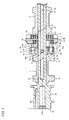
- FIG. 2 is an explanatory view illustrating a partial cross section of the variable valve device 1.
- FIG. 3 is a perspective view illustrating a partially enlarged cross section of the variable valve device 1.
- the variable valve device 1 is installed in an inline four-cylinder internal combustion engine.
- the variable valve device 1 is used for driving intake valves 53 of the internal combustion engine, but also can be used for driving exhaust valves.
- a #1 cylinder, a #2 cylinder, a #3 cylinder, and a #4 cylinder are arranged in this order from the front side. Each cylinder is provided with the two intake valves 53.
- the variable valve device 1 is provided with a drive shaft member 2 that rotates in synchronism with a crankshaft of the internal combustion engine.
- the variable valve device 1 is provided with a cam shaft member 3 that is rotatably provided in the circumference of the drive shaft member 2.
- the cam shaft member 3 includes cam lobes 3a.
- the variable valve device 1 is provided with drive arm portions 4 which are provided in the drive shaft member 2 and which rotate together with the drive shaft member 2.
- the variable valve device 1 is provided with drive disks 5-1 and 5-2 (hereinafter, collectively referred to as drive disk), and control sleeves 8.
- the drive disk rotates along an inner circumferential wall surface 8a1 of an eccentric hole 8a provided in the control sleeve 8.
- One of drive disks corresponding to the cylinder #1 is represented by the drive disk 5-1 (second rotary member).
- the others corresponding to the cylinders #2 to #4 are represented by the drive disks 5-2 (first rotary member).
- FIG. 4 is a plan view of the drive shaft member 2.
- the drive shaft member 2 is provided at its front end portion with a VVT (Variable Valve Timing) mounting portion 2a and a bearing portion 2b.
- the drive shaft member 2 is a hollow rod-shaped member, and is provided with: oil supply holes 2c for supplying lubricating oil; and a pin hole 2d for securing the drive arm portion 4 to the drive shaft member 2 by using a connection pin 13 (see FIG. 1 ).
- the pin hole 2d penetrates through the drive shaft member 2.
- the pin hole 2d is provided so as to correspond to each of the cylinders #1 to #4.
- a central axis line of the drive shaft member 2 is AX.
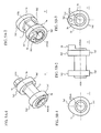
- FIG. 5A-1 is a perspective view of the cam shaft member 3.
- FIG. 5A-2 is a perspective view of the cam shaft member 3 when viewed in the direction different from FIG. 5A-1.
- FIG. 5B-1 is a left side view of the cam shaft member3.
- FIG. 5B-2 is a front view of the cam shaft member3.
- FIG.5B-3 is a right side view of the cam shaft member 3.
- the cam shaft member 3 is a tube-shaped member, and is provided with the two cam lobes 3a corresponding to the number of the intake valves 53 provided in each cylinder.
- a rotational central axis line of the cam shaft member 3 is AXcm.
- the cam shaft member 3 is rotatably provided in the circumference of the drive shaft member 2 such that the rotational central axis line AXcm coincides with the central axis line AX of the drive shaft member 2.
- the cam lobe 3a is provided with a nose portion 3a1 and a base circle portion 3a2.
- One of the two cam lobes 3a is provided at its side surface with a pin joint portion 3b. This pin joint portion 3b is connected with an end of a second link member 6b as will be detailed later.
- the cam shaft member 3 is provided for each of the cylinders #1 to #4, and is rotatably provided in the circumference of the drive shaft member 2 as illustrated in FIG. 1 to FIG. 3 .
- the cam lobe 3a comes into contact with a rocker roller 52 provided in a rocker arm 51, and causes the intake valve 53 to lift.
- FIG. 6A-1 is a perspective view of the drive arm portion 4.
- FIG. 6A-2 is a perspective view of the drive arm portion 4 when viewed in the direction different from FIG. 6A-1.
- FIG. 6B-1 is a left side view of the drive arm portion 4.
- FIG. 6B-2 is a front side view of the drive arm portion 4.
- FIG. 6B-3 is a right side view of the drive arm portion 4.
- the drive arm portion 4 is a cylindrical-shaped member, and is provided with a cylindrical-shaped portion 4a and a plate-shaped portion 4b serving as an arm.
- a rotational central axis of the drive arm portion 4, that is, the central axis line of the cylindrical-shaped portion 4a is AXd.
- the drive arm portion 4 is secured to the drive shaft member 2 such that this central axis line AXd coincides with the central axis line AX of the drive shaft member 2.
- the cylindrical-shaped portion 4a is provided with a pin hole 4a1 into which the connection pin 13 is inserted (see FIG. 1 ) in order that the drive arm portion 4 is secured to and integrated with the drive shaft member 2.
- the plate-shaped portion 4b is provided with a pin insertion hole 4b 1 for connecting an end of a first link member 6a as will be described later.
- the drive arm portion 4 is provided for each of the cylinders #1 to #4, and is secured to the drive shaft member 2 by the connection pin 13 illustrated in FIG. 1 .
- the drive arm portion 4 is provided integrally with the drive shaft member 2 and rotates together with the drive shaft member 2. Referring to FIG. 1 to FIG. 3 , the drive arm portion 4 is arranged adjacent to the cam shaft member 3. At this time, the drive arm portion 4 is attached to the drive shaft member 2 so as not to interfere with the pin joint portion 3b provided in the cam shaft member 3.
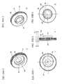
- FIG. 7 is a perspective view exemplary illustrating the drive disk 5-1.
- the drive disk 5-1 is provided with pins 5c and 5e, and a cylindrical-shaped portion 5g.
- the pins 5c and 5e project in the direction toward a surface of the drive disk 5-1, and the cylindrical-shaped portion 5g projects in the opposite direction.
- the drive disk 5-1 rotates along an inner circumferential wall surface 8a1 of the eccentric hole 8a provided in the control sleeve 8 which will be described later. Referring to FIG. 1 to FIG. 3 , the cylindrical-shaped portion 5g is inserted into the eccentric hole 8a.
- the rotational axis line of the drive disk 5-1 that is, the central axis line of the cylindrical-shaped portion 5g is AXdd, and coincides with the central axis line AX2 of the eccentric hole 8a provided in the control sleeve 8 which will be described later.
- a first bearing 9 is interposed between the inner circumferential wall surface 8a1 of the eccentric hole 8a and the cylindrical-shaped portion 5g.
- the angle A between the pin 5e and the pin 5c is, for example, 180 degrees.
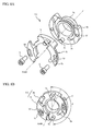
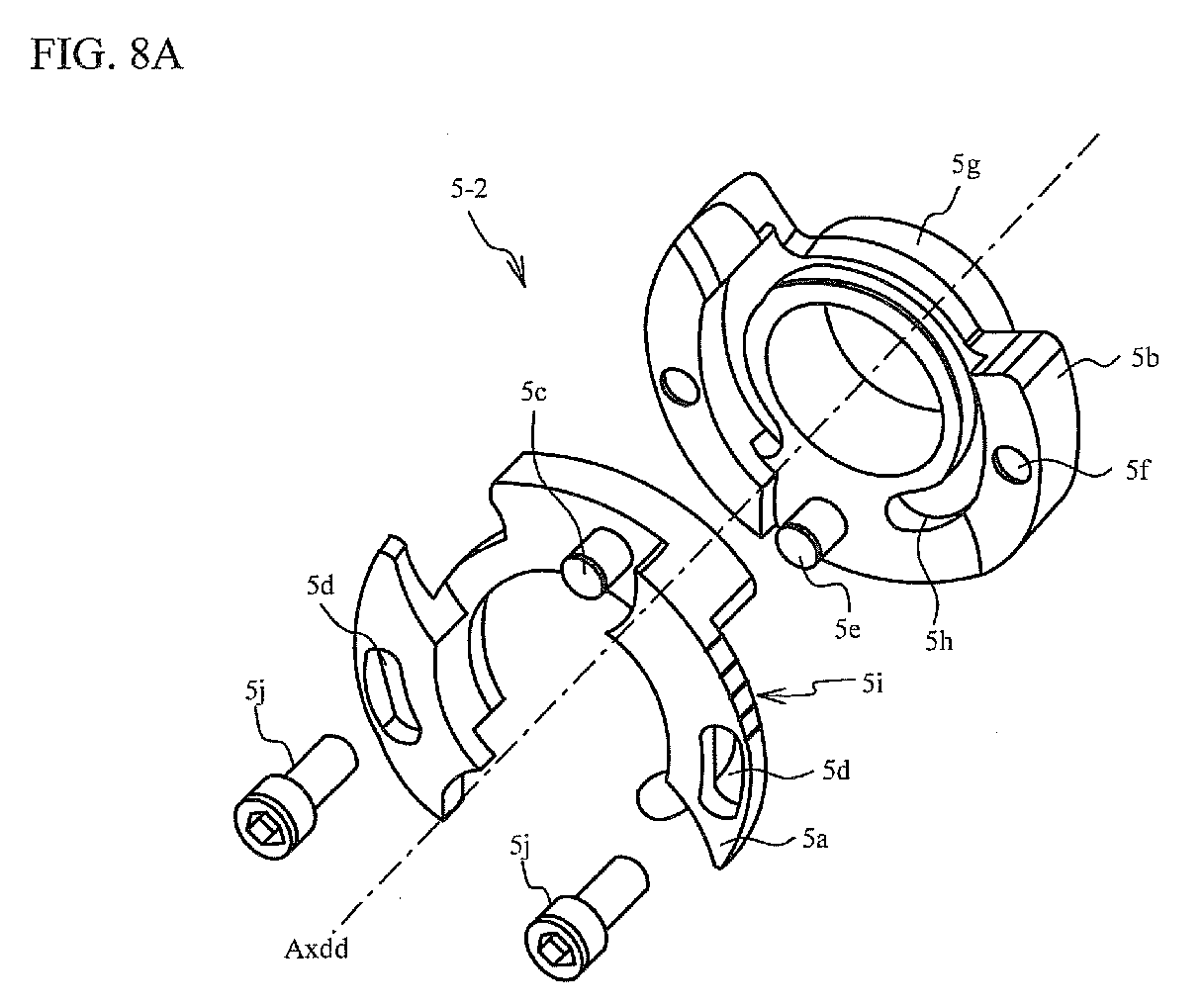
- FIG. 8A is an exploded perspective view illustrating the drive disk 5-2.
- FIG. 8B is a perspective view exemplary illustrating the drive disk 5-2.
- the drive disk 5-2 includes a drive side disk 5a (first member) and a driven side disk 5b (second member).
- the drive side disk 5a has a pin 5c and grooves 5d.
- the driven side disk 5b has a pin 5e, holes 5f, the cylindrical-shaped portion 5g, and a recess portion 5h.
- the drive side disk 5a is attached to the driven side disk 5b such that the grooves 5d overlap the holes 5f. A part of the drive disk side 5a is fitted into the recess portion 5h.
- the drive side disk 5a is secured to the driven side disk 5b by bolts 5j inserted into the grooves 5d and the holes 5f. Accordingly, the drive disk 5-2 is formed. Like the drive disk 5-1, the drive disk 5-2 rotates along the inner circumferential wall surface 8a1 of the eccentric hole 8a.
- A is 180 degrees.
- a relative position between the drive side disk 5a and the driven side disk 5b about the central axis line AX of the drive shaft member 2 is varied by loosening the bolts 5j. That is, the angle A between the pins is variable.
- a scale 5i is provided on the outer circumferential surface of the drive side disk 5a. The scale 5i can be used as a measure of the angle A between the pins. Since the drive disk 5-1 is an integral member, the angle A between the pins in the drive disk 5-1 is constant, for example, 180 degrees.
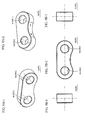
- FIG. 9A-1 is a perspective view of a first link member (second link member).
- FIG. 9A-2 is a perspective view of the first link member (second link member) when viewed in the direction different from FIG. 9A-1.
- FIG. 9B-1 is a left side view of the first link member (second link member).
- FIG. 9B-2 is a front view of the first link member (second link member).
- FIG. 9B-3 is a right side view of the first link member (second link member).
- the first link member 6a is provided with two pin insertion holes 6a1.
- the second link member 6b is provided with two pin insertion holes 6b1.
- the first link member 6a and the second link member 6b have the same shape.
- the first link member 6a and the second link member 6b are a link member for transmitting the rotation of the drive arm portion 4 to the cam shaft member 3 via the drive disk.
- An end side of the first link member 6a is connected to the drive arm portion 4 by a pin 7a, and the other end is connected to the drive disk by the pin 5c.
- the pin 7a is inserted into the pin insertion hole 4b1 provided in the drive arm portion 4 and the pin insertion hole 6a1 provided at the end side of the first link member 6a, so the drive arm portion 4 and the first link member 6a are connected by the pin connection.
- the pin 5c is inserted into the pin insertion hole 6a1 provided at the other end of the first link member 6a, so the first link member 6a and the drive disk are connected by the pin connection. Accordingly, the rotation of the drive arm portion 4 is transmitted to the drive disk.
- An end of the second link member 6b is connected to the drive disk by using the pin 5e, and the other end is connected to the cam shaft member 3 by using a pin 7b.
- the pin 5e is inserted into the pin insertion hole 6b1 provided at the end of the second link member 6b, whereby the second link member 6b and the drive disk are connected by the pin connection.
- the pin 7b is inserted into the pin insertion hole 6b1 provided at the other end of the second link member 6b and into a pin insertion hole 3b1 of the cam shaft member 3, whereby the second link member 6b and the cam shaft member 3 are connected by the pin connection. Accordingly, the rotation of the drive disk is transmitted to the cam shaft member 3.
- first link member 6a and the second link member 6b transmit the rotation of the drive arm portion 4 to the cam shaft member 3 via the drive disk.
- first link member 6a is connected to the drive side disk 5a
- second link member 6b is connected to the driven side disk 5b.
- Both the first link member 6a and the second link member 6b are disposed in the pins 5e and 5c side of the drive disk.
- the control sleeve 8, a second bearing 10, a third bearing 11, a cap 12 are disposed in the cylindrical-shaped portion 5g side.
- FIG. 10A-1 is a perspective view of the control sleeve 8
- FIG. 10A-2 is a perspective view of the control sleeve 8 when viewed in the direction different from FIG. 10A-1.
- FIG. 10B-1 is a left side view of the control sleeve 8
- FIG. 10B-2 is a front view of the control sleeve 8
- FIG. 10B-3 is a right side view of the control sleeve 8.
- the control sleeve 8 is provided with the eccentric hole 8a, with a gear portion 8b (first gear portion) at its outer circumferential surface, and with a cylindrical-shaped portion 8c.
- the rotational central axis line AX1 of the control sleeve 8 coincides with a central axis line about an inner circumference of the cylindrical-shaped portion 8c. This rotational central axis line AX1 is different from the central axis line AX2 of the eccentric hole 8a.
- the drive shaft member 2 is inserted into the eccentric hole 8a and the cylindrical-shaped portion 8c.
- the central axis line AX of the drive shaft member 2 inserted into the eccentric hole 8a and the cylindrical-shaped portion 8c coincides with the rotation central axis line AX1 of the control sleeve 8, that is, the central axis line of the cylindrical-shaped portion 8c.
- the cylindrical-shaped portion 5g of the drive disk 5 is rotatably mounted to the eccentric hole 8a via the first bearing 9.
- the interposition of the second bearing 10 between the drive shaft member 2 and the cylindrical-shaped portion 8c causes the drive shaft member 2 to be supported within the cylindrical-shaped portion 8c via the second bearing 10.
- the third bearing 11 is mounted on the outside of the cylindrical-shaped portion 8c, and the cap 12 is disposed in the outer side of the third bearing 11.
- both the control sleeve 8 and the drive shaft member 2 are mounted together on the internal combustion engine.
- the gear portion 8b is meshed with a gear portion 15a provided in an outer circumferential surface of a control shaft 14, as illustrated in FIG. 10B-2 , and causes the control sleeve 8 to rotate in response to the rotation of the control shaft 14.
- the rotation of the control sleeve 8 varies the position of the central axis line AX2 of the eccentric hole 8a. This will be described in detail later.
- a position of the central axis line AX2 which has been adjusted to the height of an end surface of a cam cap 55 to be described later serves as a reference position.
- the working angle in the reference position serves as a reference working angle.
- the control sleeve 8 is rotated to one side from this state, so the rotational speed of the cam shaft member 3 increases during the time the intake valve 53 is opened, and the rotational speed of the cam shaft member 3 decreases during the time the intake valve 53 is closed.
- the drive shaft member 2 is rotated in this state, so that the valve opening timing of the intake valve 53 is advanced and the valve closing timing is retarded, which increases the working angle.
- the control sleeve 8 is rotated from the reference position to the other side, the working angle is reduced. This will be described in detail later.
- the cam shaft member 3, the drive arm portion 4, the drive disk, and the control sleeve 8 are provided for each of the cylinders #1 to #4.
- the cam shaft member 3 and the drive arm portion 4 are mounted on the drive shaft member 2 inserted thereinto.
- the drive arm portion 4 is secured to the drive shaft member 2 by using the connection pin 13.
- the drive disk attached with the first link member 6a and the second link member 6b in the side from which the pins 5c and 5e protrude, and the control sleeve 8 are mounted.
- the first bearing 9 and the second bearing 10 are mounted on the cylindrical-shaped portion 8c positioned in the rear end side of the control sleeve 8.
- the cap 12 is disposed around the second bearing 10 when the variable valve device 1 is mounted on the internal combustion engine.
- the combination of the first bearing 9, the second bearing 10, and the cap 12 is provided for each cylinder. That is, the variable valve device 1 is supported by four points of the internal combustion engine.
- the drive shaft member 2 and the control sleeve 8 can be supported by the internal combustion engine without separating the space for supporting the drive shaft member 2 by the internal combustion engine from the space for supporting the control sleeve 8 by the internal combustion engine. That is, the variable valve device 1 has a good mounting property to the internal combustion engine.
- the combination of the first bearing 9, the second bearing 10, and the cap 12 is provided for every cylinder. That is, the variable valve device 1 is supported by four points of the internal combustion engine. This can ensure the rigidity of the valve system.
- the target valve lift can be achieved without swinging the rotational axis line of the cam lobe 3a, which enables a good valve lift waveform.
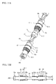
- FIG. 11A is an enlarged perspective view of the control shaft 14.
- FIG. 11B is a sectional view illustrating the control shaft 14. As illustrated in FIG. 11A , the control shaft 14 is provided close to the drive shaft member 2.
- the central axis line AXC of the control shaft 14 faces in the direction same as the direction in which the central axis line AX of the drive shaft member 2 faces.
- the control shaft 14 is provided at its outer circumference with pinions corresponding to respective cylinders.
- One of the pinions corresponding to the cylinder #1 is a pinion 15-1.
- the pinions corresponding to the cylinders #2 to #4 are pinions 15-2.
- the gear portions 15a are formed on the outer circumferential surfaces of the pinions 15-1 and 15-2.
- the gear portion 15a engages the gear portion 8b of the control sleeve 8.
- the pinion 15-1 is secured to the control shaft 14 by a pin 16b penetrating through the pinion 15-1 and the control shaft 14.
- the gear portion 15a of the pinion 15-1 (second gear portion) is secured to the control shaft 14.
- the pinion 15-1 is inserted into a needle bearing 17, a washer 20, and a bush 19-1, and the bush 19-1 is secured to the control shaft 14 by the pin 16b.
- the pinion 15-2 is secured to the control shaft 14 by the needle bearing 17, a nut 18, and a bush nut 19-2.
- the pinion 15-2 is inserted into the needle bearing 17 and the washer 20.
- the bush nut 19-2 is secured to the control shaft 14 by the pin 16b.
- the nut 18 tightens a screw portion 15b of the pinion 15-2.
- the pinion 15-2 is rotatable by loosening the nut 18. That is, the gear portion 15a of the pinion 15-2 (third gear portion) is rotatable about the central axis line AXC.
- FIG. 12 is a perspective view illustrating a state where the variable valve device 1 is mounted on a cam housing 54.
- the drive shaft member 2 and the control shaft 14 are mounted to the cam housing 54.
- the drive shaft member 2 is secured to the cam housing 54 by the cam cap 55
- the control shaft 14 is secured to the cam housing 54 by a control shaft cap 56.
- a drive shaft member 57 is mounted to the cam housing 54.
- a cam piece 58 provided on the drive shaft member 57 opens and closes an exhaust valve not illustrated.
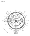
- FIG. 13 is a sectional view exemplary illustrating the variable valve device 1, and illustrates a portion corresponding to the cylinder #1. This corresponds to a cross section taken long line E-E of FIG. 3 . As indicated by an arrow R in FIG. 13 , the drive shaft member 2 rotates clockwise.
- the eccentric hole 8a is offset to the left relative to the central axis line AX of the drive shaft member 2.
- the straight line L1 is a straight line connecting the central axis line AX of the drive shaft member 2 and the central axis of the eccentric hole 8a of the control sleeve 8.
- the angle ⁇ is a rotational angle of the cam lobe 3a relative to the drive shaft member 2.
- the rotational angle ⁇ is a rotational angle of the drive shaft member 2 on the basis of the direction perpendicular to the end surface of the cam cap 55 (vertical direction in FIG. 13 ).
- central axis line AX coincides with the rotational central axis line AX1 of the control sleeve 8.
- varying the direction of the eccentricity of the eccentric holes 8a that is, varying the eccentric angle ⁇ varies the angle ⁇ .
- the variation in the angle ⁇ varies the rotational speed of the cam lobe 3a.
- a circle S2 indicated by a dotted line in FIG. 13 represents the locus of the center of the eccentric hole 8a.
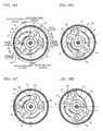
- FIG. 14A to FIG. 14D are sectional views exemplary illustrating the operation of the variable valve device 1, and illustrate a cross section taken along line F-F of FIG. 3 .
- FIG. 14A and FIG. 14B when the drive arm portion 4 is positioned within the deceleration range, the rotational speed of the cam lobe 3a is lower than that of the drive shaft member 2.
- FIG. 14C and FIG. 14D when the drive arm portion 4 is positioned in the acceleration range, the rotational speed of the cam lobe 3a is higher than that of the drive shaft member 2. Broad ranges and narrow ranges will be described.
- FIG. 14A and FIG. 14D when the drive arm portion 4 is positioned within the wide range, the angle ⁇ is greater than 180 degrees. As illustrated in FIG. 14B and FIG.
- the angle ⁇ is smaller than 180 degrees.
- the cam lobe 3a in a position to be advanced relative to the drive arm portion 4.
- the cam lobe 3a is in a position to be retarded relative to the drive arm portion 4.
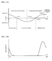
- FIG. 15A is a schematic view exemplary illustrating a relationship between the rotational angle ⁇ and the angle ⁇ .
- a vertical axis represents the rotational angle ⁇
- a horizontal axis represents the angle ⁇ .
- FIG. 15B is a schematic view exemplary illustrating a lift amount.
- a horizontal axis represents the rotational angle ⁇
- a horizontal axis represents the lift amount of the intake valve 53.
- the speed of the cam lobe 3a is the same as that of the drive arm portion 4.
- the cam lobe 3a is advanced from the drive arm portion 4.
- ⁇ -180° ⁇ 0 that is, in case of ⁇ ⁇ 180°
- the cam lobe 3a is retarded from the drive arm portion 4.
- the drive arm portion 4 is positioned in the wide range and the deceleration range. That is, the angle ⁇ is greater than 180 degrees, and the cam lobe 3a is decelerating.
- ⁇ becomes smaller as the rotational angle ⁇ becomes greater.
- the drive arm portion 4 enters the narrow range.
- the angle ⁇ is smaller than 180 degrees.
- the drive arm portion 4 enters the deceleration range, and the cam lobe 3a is shifted from the deceleration to the acceleration.
- the drive arm portion 4 enters the wide range, and the angle ⁇ is greater than 180 degrees.
- the drive arm portion 4 enters the deceleration range, and the cam lobe 3a starts decelerating.
- the control sleeve 8 is rotated counterclockwise by 65 degrees from the state illustrated in FIG. 16A .
- ⁇ varies, whereby the valve opening/closing timing and the working angle vary.
- FIG. 17A is a schematic view exemplary illustrating a relationship between the rotational angle ⁇ and the angle ⁇ .
- FIG. 17B is a schematic view exemplary illustrating the lift amount.
- the eccentric angle ⁇ can vary the valve opening/closing timing and the working angle.
- the internal combustion engine is provided with the cylinders #1 to #4.
- component tolerances might change the valve opening/closing timing (working angle) in each of the cylinders #1 to #4. This might cause a change in an intake air amount and in a residual gas amount in the cylinder. This might result in making it difficult to ensure appropriate combustion, which might cause deterioration in fuel consumption and exhaust, a reduction in output, deterioration in drivability, damage to components of the internal combustion engine, or the like.
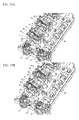
- FIG. 18A to FIG. 18C are perspective views exemplary illustrating adjustment of an angle A between pins in the drive disk 5-2.
- the drive side disk 5a or the driven side disk 5b is rotated by loosening the bolts 5j, so that the angle A between the pins is varied.
- FIG. 19 is a perspective view illustrating the adjustment of the eccentric angle ⁇ . As indicated by an arrow in illustrated FIG. 19 , loosening the nut 18 allows the pinion 15-2 to rotate. Rotating the pinion 15-2 varies the meshing of the gear portion 15a with the gear portion 8b of the control sleeve 8. This varies the eccentric angle ⁇ of the eccentric hole 8a.
- FIG. 20A is a graph exemplary illustrating a relationship among the angle A between the pins, the valve opening timing, and the working angle.
- the horizontal axis indicates the angle A between the pins, and the vertical axis in the right side and the dashed line indicate the working angle.
- the vertical axis in the left side and the solid line indicate the valve opening timing.
- the working angle slightly varies, but the valve opening timing drastically varies.
- the working angle is about two degrees or minus two degrees CA, and the valve opening timing is about ten degrees to minus ten degrees CA.
- the valve opening/closing timing varies with the valve opening timing.
- FIG. 20B is a graph exemplary illustrating a relationship among the rotational angle of the control sleeve 8, the valve opening timing, and the working angle.
- the horizontal axis represents the rotational angle of the control sleeve 8.
- Rotating the control sleeve 8 varies the eccentric angle ⁇ .
- the rotational angle is negative when the control sleeve 8 is rotated counterclockwise, and the rotational angle is positive, when it is rotated clockwise.
- the rotational angle decreases and the valve opening timing is retarded.
- valve opening timing When the rotational angel is positive, the working angle increases and the valve opening timing is advanced.
- the valve opening timing slightly varies, but the working angle drastically varies.
- the valve opening timing is about two degrees to minus one degree CA, and the working angle is about minus nine degrees to nine degrees CA.
- the valve opening/closing timing varies with the working angle.
- varying the angle A between the pins in the drive disk 5-2 can adjust the valve opening timing.
- Rotating the pinion 15-2 can vary the position of the eccentric holes 8a and adjust the working angle.
- the adjustment of the working angle can adjust the valve closing timing. This suppresses a change in the valve opening timing amoung the cylinders.
- a description will be given of the adjustment of the valve opening timing and the working angle.
- the drive disk 5-1 corresponding to the cylinder #1 is used as a reference of the valve opening/closing timing. Since the drive disk 5-1 is an integral member, the variation in the angle A between the pins illustrated in FIG. 18A to FIG. 18C is not performed.
- the pinion 15-1 corresponding to the cylinder #1 is used as a reference of the working angle (valve closing timing). Since the pinion 15-1 is secured to the control shaft 14, its rotation is not performed by the method as illustrated in FIG. 19A .
- the valve opening/closing timing and the working angle (valve closing timing) in the cylinders #2 to #4 are approached to the valve opening/closing timing and the working angle in the cylinder #1.
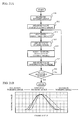
- FIG. 21A is a flowchart exemplary illustrating a process of the adjustment.
- the working angles of all intake valves 53 are set to the maximum working angles (step S10).
- the valve opening/closing timing in the cylinders #1 to #4 are measured (step S 11). This is because the valve opening/closing timing is drastically changed in the maximum working angle.
- a valve opening timing adjustment amount and a working angle (valve closing timing) adjustment amount are determined (step S12).
- the valve opening timing adjustment amount is an adjustment amount of the valve opening timing to set the valve opening timing in the cylinders #2 to #4 to an allowable value as compared with the valve opening timing in the cylinder #1 serving as a reference.
- the working angle adjustment amount is an adjustment amount of the working angle to set the working angles (valve closing timings) in the cylinders #2 to #4 to allowable values as compared to the working angle (valve closing timing) in the cylinder #1 serving as a reference.
- the valve opening timing is adjusted (step S 13).
- the working angle (valve closing timing) is adjusted (step S 14).
- the valve opening/closing timing is measured (step S15), and it is determined whether or not the valve opening/closing timing is within the allowable range (step S16). When No is determined, steps S12 to S 15 are performed again. If Yes is determined, the work is finished.
- FIG. 21B is a schematic view exemplary illustrating the working angle.
- the horizontal axis represents the crank angle, and the vertical axis represents the working angle.
- the working angles are set to the maximum working angles within these angles (step S10 in FIG. 21A ).
- FIG. 22A and FIG. 22B are sectional views exemplary illustrating measurement of the valve opening timing.
- a mark 55a is provided in the cam cap 55.
- the control sleeve 8 is rotated such that a mark 8d provided in the control sleeve 8 faces the mark 55a. Therefore, the working angle is maximized.
- the drive shaft member 2 is rotated, so the intake valve 53 is opened and closed. This enables to measure the valve opening/closing timing (step S 11 in FIG. 21(a) ).
- a lifter 59 for inspection may be used for measuring the valve opening/closing timing.
- FIG. 23A and FIG. 23B are perspective views exemplary illustrating the adjustment of the angle A between the pins.
- the drive shaft member 2 and the control shaft 14 illustrated in FIG. 23A are secured by, for example, a jig. Accordingly, the drive arm portion 4, the first link member 6a, and the control sleeve 8 are secured. Therefore, the drive side disk 5a connected to the drive arm portion 4 does not move.
- One of the bolts 5j is loosened, the securement of the drive shaft member 2 is temporarily released and rotated, and the drive shaft member 2 is secured again. Then, the other bolt 5j is loosened to bring the driven side disk 5b into the movable state. As indicated by arrows in FIG.
- the driven side disk 5b is rotated by hand or a jig. This adjusts the angle A between the pins to adjust the valve opening/closing timing within a desired range.
- the scale 5i is provided in the outer circumferential surface of the drive side disk 5a. The scale 5i can be used as a reference of the adjustment of the angle A between the pins.
- the driven side disk 5b may be rotated by rotating the cam shaft member 3. A shim or the like may be sandwiched between the drive side disk 5a and the driven side disk 5b.
- FIG. 24 is a sectional view exemplary illustrating the adjustment of the position of the gear.
- a scale 55b is provided in the cam cap 55.
- One division of the scale 55b corresponds to, for example, the working angle one degree CA.
- the control sleeve 8 is rotated by rotating the pinion 15-2.
- the working angle (the valve closing timing) is set to a desired magnitude by use of the scale 55b.
- the drive side disk 5a and the driven side disk 5b are rotatable independently of each other. Therefore, the valve opening timing can be set to a desired magnitude by adjusting the angle A between the pins.
- the angle A between the pins in the drive disk 5-2 can be adjusted based on the drive disk 5-1 of the integrated member. It is thus possible to suppress a change in the valve opening timing among the cylinders.
- the rotation of the gear portion 15a of the pinion 15-2 can adjust the working angle (valve closing timing).
- the pinion 15-1 is rotated based on the pinion 15-1 secured to the control shaft 14. It is thus possible to suppress a change in the working angle (valve closing timing) among the cylinders.
- the adjustment of the valve opening timing and the working angle (valve closing timing) can suppress a change in the valve opening/closing timing.
- the drive disk 5-2 and the pinion 15-2 may be provided for every cylinder.
- One of the drive disks 5-2 can be used as a reference of the valve opening timing, and one of the pinions 15-2 can be used as a reference of the working angle (valve closing timing).
- the drive disk 5-1 and the pinion 15-1 may be provided for the cylinders other than the cylinder #1.
- the drive disk 5-1 and the pinion 15-1 may be provided to correspond to two or more cylinders. That is, the drive disk 5-1 and the pinion 15-1 have only to be provided to correspond to at least one of the cylinders.
- the four-cylinder internal combustion engine has been described as an example, but the first embodiment is applicable to other internal combustion engines such as an eight-cylinder internal combustion engine other than the four-cylinder internal combustion engine.
- the cylinder #1 serving as a reference has the following values.
- valve opening timing is advanced, the working angle is large, and the valve closing timing is retarded, as compared with the references.
- the references are the same as the above.
- the cylinder to be adjusted has the following values.
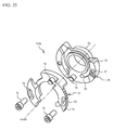
- FIG. 25 is an exploded perspective view exemplary illustrating the drive disk 5-2a of the variable valve device according to the first variation of the first embodiment.
- a surface, of the driven side disk 5b, facing the drive side disk 5a is provided on projections 5k.
- the interval between the adjacent projections 5k is equivalent to, for example, from 0.5 degrees to 1 degree. Using the projections 5k enables the adjustment of the angle A between the pins.
- FIG. 26A is a perspective view exemplary illustrating a cross section of a drive disk 5-2b of a variable valve device according to a second variation of the first embodiment. As illustrated in FIG. 26A , a tapered portion 51 of the drive side disk 5a engages the recess portion 5h. Thus, the drive side disk 5a is firmly secured to the driven side disk 5b.
- FIG. 26B is a perspective view exemplary illustrating a drive disk 5-2c of a variable valve device according to the third variation of the first embodiment.
- a screw 5m is inserted into the outer circumferential surface of the driven side disk 5b.
- the screw 5m secures the drive side disk 5a engaging the recess portion 5h of the driven side disk 5b.
- the securement between the disks may use, for example, an adhesive or the like.
- the outer circumferential surface of the drive side disk 5a is provided with a hole 5n
- the outer circumferential surface of the driven side disk 5b is provided with a hole 5o. The holes 5n and 5o will be described later.
- FIG. 27A and FIG. 27B are perspective views exemplary illustrating adjustment of an angle A between pins in the third variation.
- the driven side disk 5b is rotated by using a jig inserted into the hole 5o. It is thus possible to adjust the angle A between the pin.
- the drive disk side 5a is secured by inserting the jig into the hole 5n. Afterward, the driven side disk 5b may be rotated.
- FIG. 28A is a perspective view exemplary illustrating a drive disk 5-2d of a variable valve device according to the fourth variation.
- FIG. 28B is an exploded perspective view exemplary illustrating the drive disk 5-2d.
- a side, of the drive side disk 5a, facing the driven side disk 5b is provided with a gear portion 5p.
- the drive side disk 5a and the driven side disk 5b are assembled such that the gear portion 5p can be seen through the hole 5o.
- FIG. 29 is a top view exemplary illustrating adjustment of an angle A between the pins.
- the jig (not illustrated) is inserted into the hole 5o illustrated in FIG. 29, thereby connecting the jig and the gear portion 5p.
- rotating the driven side disk 5b can adjust the angle A between the pins.
- the jig is provided with a gear engageable with the gear portion 5p or the like. This is because the rotation of the drive side disk 5a is facilitated.
- the number of the bolts 5j is variable, and may be three or four.
- a nut for reinforcing the bolts 5j may be used.
- the adhesive may be combined.
- the drive side disk 5a and the driven side disk 5b sandwiching a wear agent may be secured to each other. Also, the variation example may be combined.
- FIG. 30A to FIG. 30D are schematic views exemplary illustrating an example of the arrangement of the parts.
- the pin 5c which is a connection point of the drive disk and the first link member 6a, the pin 5e which is a connection point of the drive disk and the second link member 6b, the pin 7a which is a connection point of the first link member 6a and the drive arm portion 4, and the pin 7b which is a connection point of the second link member 6b and the cam shaft member 3 are each depicted by a black dot.
- the first link member 6a is depicted by a line between 5c and 7a
- the second link member 6b is depicted by a line between 5e and 7b.
- a dotted circle represents the rocker roller 52.
- the rotational direction is clockwise in the drawings.
- FIG. 30A is a schematic view illustrating an example of the arrangement and illustrating the same arrangement as the first embodiment.
- the pin 7b is positioned in the rotational direction side relative to the pin 5c between 5e and 5c.
- the pin 7a is positioned in the rotational direction side relative to the pin 5e between 5c and 5e.
- the compressive force is generated such the drive arm portion 4 pushes the first link member 6a in the rotational direction against the spring force of the intake valve 53.
- the tensile force is generated such that the second link member 6b pulls the cam shaft member 3 in the rotational direction.
- the tensile force is generated by the spring force such that the first link member 6a pulls the drive arm portion 4, and the compressive force is generated such that the cam shaft member 3 pushes the second link member 6b.
- the pin 7b is positioned in the rotational direction side relative to the pin 5e between 5c and 5e.
- the pin 7a is positioned in the rotational direction side relative to 5c between 5e and 5c.
- the tensile force is generated in the first link member 6a, and the compressive force is generated in the second link member 6b.
- the compressive force is generated in the first link member 6a, and the tensile force is generated in the second link member 6b.
- the pins 7a and 7b are positioned in the rotational direction side relative to the pin 5e between 5c and 5e.
- the pins 7a and 7b are arranged in the order of being close to the pin 5c.
- the compressive force is generated in the first link member 6a and the second link member 6b.
- the tensile force is generated in the first link member 6a and the second link member 6b.
- the pins 7a and 7b are positioned in the rotational direction side relative to the pin 5c between 5c and 5e.
- the pins 7a and 7b are arranged in the order of being close to the pin 5c.
- the tensile force is generated in the first link member 6a and the second link member 6b.
- the compressive force is generated in the first link member 6a and the second link member 6b.
- the first embodiment is applicable to a variable valve device for opening and closing the exhaust valves.
Landscapes
- Engineering & Computer Science (AREA)
- Mechanical Engineering (AREA)
- General Engineering & Computer Science (AREA)
- Valve Device For Special Equipments (AREA)
Abstract
Description
- The present invention is related to a variable valve device.
- Conventionally, there is known a variable valve device for variably controlling an working angle of a cam driving an intake valve or an exhaust valve installed in an internal combustion engine. For example,
Patent Document 1 describes a variable valve device for varying the working angle by using a non-constant velocity universal joint. - [Patent Docuemnt 1] Japanese Unexamined Patent Application Publication No.
11-62531 - In the conventional art, there is a possibility to cause a change in the valve opening/closing timing for every cylinder. In view of the above circumstances, it is an object of the present invention to provide a variable valve device capable of suppressing a change in the valve opening/closing timing.
- The present invention is a variable valve device including: a drive shaft member rotating synchronously with a crankshaft provided in an internal combustion engine; a cam shaft member including a cam lobe and rotatably provided about the drive shaft member; a drive arm portion provided in the drive shaft member and rotating together with the drive shaft member; a control sleeve provided with an eccentric hole into which the drive shaft member is inserted, and arranged to vary a position of a central axis of the eccentric hole; and a first rotary member including a first member connected to the drive arm portion and a second member connected to the cam shaft member, and rotating along an inner circumferential wall surface of the eccentric hole, wherein the first rotary member rotates in a state where the first member and the second member are secured to each other, a relative position between the first member and the second member about a central axis line of the drive shaft member is variable.
- In the above configuration, there may be provided: a first link member connected to the rotary arm portion and the first member; and a second link member connected to the cam shaft member and the second member, wherein an angle about the central axis line between a connection point of the first member and the first link member and a connection point of the second member and the second link member may be variable.
- In the above configuration, the cam shaft member, the drive arm portion, and the control sleeve may be provided for every cylinder of an internal combustion engine, a second rotary member may be provided to correspond to at least one of the cylinders, may rotate along the inner circumferential wall surface of the eccentric hole, and may be an integrated member, and the first rotary member may be provided to correspond to the cylinder other than the at least one of the cylinders among the cylinders.
- In the above configuration, the control sleeve may include a first gear portion in an outer circumferential surface, there may be provide: a control shaft facing in a direction same as a direction in which the drive shaft faces; a second gear portion corresponding to at least one of the cylinders, provided in an outer circumference of the control shaft, engageable with the first gear portion, and secured to the control shaft; and a third gear portion corresponding to the cylinder other than the at least one of the cylinders among the cylinders, provided in an outer circumference of the control shaft, engageable with the first gear portion, and rotatable about a central axis line of the control shaft independently of the second gear portion.
- According to the present invention, it is possible to provide a variable valve device capable of suppressing a change in valve opening/closing timing.
-
-
FIG. 1 is a perspective view illustrating a variable valve device according to the first embodiment; -
FIG. 2 is an explanatory view illustrating a partial cross section of the variable valve device; -
FIG. 3 is a perspective view illustrating a partially enlarged cross section of thevariable valve device 1; -
FIG. 4 is a plan view of a drive shaft member; -
FIG. 5A-1 is a perspective view of a cam shaft member,FIG. 5A-2 is a perspective view of the cam shaft member when viewed in the direction different fromFIG. 5A-1, FIG. 5B-1 is a left side view of the cam shaft member,FIG. 5B-2 is a front view of the cam shaft member, andFIG. 5B-3 is a right side view of the cam shaft member; -
FIG. 6A-1 is a perspective view of a drive arm portion,FIG. 6A-2 is a perspective view of the drive arm portion when viewed in the direction different fromFIG. 6A-1, FIG. 6B-1 is a left side view of the drive arm portion,FIG. 6B-2 is a front side view of the drive arm portion, andFIG. 6B-3 is a right side view of the drive arm portion; -
FIG. 7 is a perspective view exemplary illustrating a drive disk; -
FIG. 8A is an exploded perspective view illustrating the drive disk, andFIG. 8B is a perspective view exemplary illustrating the drive disk; -
FIG. 9A-1 is a perspective view of a first link member (second link member),FIG. 9A-2 is a perspective view of the first link member (second link member) when viewed in the direction different fromFIG. 9A-1, FIG. 9B-1 is a left side view of the first link member (second link member),FIG. 9B-2 is a front view of the first link member (second link member), andFIG. 9B-3 is a right side view of the first link member (second link member); -
FIG. 10A-1 is a perspective view of a control sleeve,FIG. 10A-2 is a perspective view of the control sleeve when viewed in the direction different fromFIG. 10A-1, FIG. 10B-1 is a left side view of the control sleeve,FIG. 10B-2 is a front view of the control sleeve, andFIG. 10B-3 is a right side view of the control sleeve, -
FIG. 11A is an enlarged perspective view of a control shaft, andFIG. 11B is a sectional view illustrating the control shaft; -
FIG. 12 is a perspective view exemplary illustrating a state where the variable valve device is mounted on a cam housing; -
FIG. 13 is a sectional view exemplary illustrating the variable valve device; -
FIG. 14A to FIG. 14D are sectional views exemplary illustrating an operation of the variable valve device; -
FIG. 15A is a schematic view exemplary illustrating a relationship between a rotational angle δ and an angle θ, andFIG. 15B is a schematic view exemplary illustrating a lift amount; -
FIG. 16A is a schematic view exemplary illustrating the operation of the variable valve device in case of φ=180°,FIG. 16B is a schematic view exemplary illustrating the operation of the variable valve device in case of φ=150°, andFIG. 16C is a schematic view exemplary illustrating the operation of the variable valve device in case of φ=245°; -
FIG. 17A is a schematic view exemplary illustrating a relationship between the rotational angle δ and the angle θ, andFIG. 17B is a schematic view exemplary illustrating the lift amount; -
FIG. 18A to FIG. 18C are perspective views exemplary illustrating adjustment of an angle A between pins in the drive disk; -
FIG. 19 is a perspective view exemplary illustrating adjustment of an eccentric angle φ; -
FIG. 20A is a graph exemplary illustrating a relationship among the angle A between the pins, a valve opening timing, and a working angle, andFIG. 20B is a graph exemplary illustrating a relationship among the rotational angle, the valve opening timing, and the working angle; -
FIG. 21A is a flowchart exemplary illustrating a process of the adjustment, andFIG. 21B is a schematic view exemplary illustrating the working angle; -
FIG. 22A and FIG. 22B are sectional views exemplary illustrating measurement of the valve opening timing; -
FIG. 23A and FIG. 23B are perspective views exemplary illustrating the adjustment of the angle A between the pins; -
FIG. 24 is a sectional view exemplary illustrating adjustment of a position of a gear; -
FIG. 25 is an exploded perspective view exemplary illustrating the drive disk of the variable valve device according to the first variation of the first embodiment; -
FIG. 26A is a perspective view exemplary illustrating a cross section of a drive disk of a variable valve device according to the second variation of the first embodiment, andFIG. 26B is a perspective view exemplary illustrating a drive disk of a variable valve device according to the third variation of the first embodiment; -
FIG. 27A and FIG. 27B are perspective views exemplary illustrating adjustment of an angle A between pins in the third variation; - FIG. 28A is a perspective view exemplary illustrating a drive disk of a variable valve device according to the fourth variation, and FIG. 28B is an exploded perspective view exemplary illustrating the drive disk;
- FIG. 29 is a top view exemplary illustrating adjustment of an angle A between the pins; and
-
FIG. 30A to FIG. 30D are schematic views exemplary illustrating an example of the arrangement of parts. - An embodiment according to the present invention will be described with reference to the accompanying drawings. However, a dimension and a ratio of each component illustrated in the drawings may not correspond to the reality.
- The first embodiment is an example of adjustment of an working angle and valve opening timing.
FIG. 1 is a perspective view illustrating avariable valve device 1 according to the first embodiment.FIG. 2 is an explanatory view illustrating a partial cross section of thevariable valve device 1.FIG. 3 is a perspective view illustrating a partially enlarged cross section of thevariable valve device 1. Thevariable valve device 1 is installed in an inline four-cylinder internal combustion engine. Thevariable valve device 1 is used for drivingintake valves 53 of the internal combustion engine, but also can be used for driving exhaust valves. In the internal combustion engine, a #1 cylinder, a #2 cylinder, a #3 cylinder, and a #4 cylinder are arranged in this order from the front side. Each cylinder is provided with the twointake valves 53. - As illustrated in
FIG. 1 to FIG. 3 , thevariable valve device 1 is provided with adrive shaft member 2 that rotates in synchronism with a crankshaft of the internal combustion engine. Thevariable valve device 1 is provided with acam shaft member 3 that is rotatably provided in the circumference of thedrive shaft member 2. Thecam shaft member 3 includescam lobes 3a. Thevariable valve device 1 is provided withdrive arm portions 4 which are provided in thedrive shaft member 2 and which rotate together with thedrive shaft member 2. Thevariable valve device 1 is provided with drive disks 5-1 and 5-2 (hereinafter, collectively referred to as drive disk), and controlsleeves 8. The drive disk rotates along an inner circumferential wall surface 8a1 of aneccentric hole 8a provided in thecontrol sleeve 8. One of drive disks corresponding to thecylinder # 1 is represented by the drive disk 5-1 (second rotary member). The others corresponding to thecylinders # 2 to #4 are represented by the drive disks 5-2 (first rotary member). -
FIG. 4 is a plan view of thedrive shaft member 2. As illustrated inFIG. 4 , thedrive shaft member 2 is provided at its front end portion with a VVT (Variable Valve Timing) mountingportion 2a and a bearingportion 2b. Thedrive shaft member 2 is a hollow rod-shaped member, and is provided with: oil supply holes 2c for supplying lubricating oil; and apin hole 2d for securing thedrive arm portion 4 to thedrive shaft member 2 by using a connection pin 13 (seeFIG. 1 ). Thepin hole 2d penetrates through thedrive shaft member 2. Thepin hole 2d is provided so as to correspond to each of thecylinders # 1 to #4. A central axis line of thedrive shaft member 2 is AX. -
FIG. 5A-1 is a perspective view of thecam shaft member 3.FIG. 5A-2 is a perspective view of thecam shaft member 3 when viewed in the direction different fromFIG. 5A-1. FIG. 5B-1 is a left side view of the cam shaft member3.FIG. 5B-2 is a front view of the cam shaft member3.FIG.5B-3 is a right side view of thecam shaft member 3. As illustrated inFIG. 5A-1 to FIG. 5B-3 , thecam shaft member 3 is a tube-shaped member, and is provided with the twocam lobes 3a corresponding to the number of theintake valves 53 provided in each cylinder. A rotational central axis line of thecam shaft member 3 is AXcm. Thecam shaft member 3 is rotatably provided in the circumference of thedrive shaft member 2 such that the rotational central axis line AXcm coincides with the central axis line AX of thedrive shaft member 2. Thecam lobe 3a is provided with a nose portion 3a1 and a base circle portion 3a2. One of the twocam lobes 3a is provided at its side surface with a pinjoint portion 3b. This pinjoint portion 3b is connected with an end of asecond link member 6b as will be detailed later. Thecam shaft member 3 is provided for each of thecylinders # 1 to #4, and is rotatably provided in the circumference of thedrive shaft member 2 as illustrated inFIG. 1 to FIG. 3 . Thecam lobe 3a comes into contact with arocker roller 52 provided in arocker arm 51, and causes theintake valve 53 to lift. -
FIG. 6A-1 is a perspective view of thedrive arm portion 4.FIG. 6A-2 is a perspective view of thedrive arm portion 4 when viewed in the direction different fromFIG. 6A-1. FIG. 6B-1 is a left side view of thedrive arm portion 4.FIG. 6B-2 is a front side view of thedrive arm portion 4.FIG. 6B-3 is a right side view of thedrive arm portion 4. As illustrated inFIG. 6A-1 to FIG. 6B-3 , thedrive arm portion 4 is a cylindrical-shaped member, and is provided with a cylindrical-shapedportion 4a and a plate-shapedportion 4b serving as an arm. A rotational central axis of thedrive arm portion 4, that is, the central axis line of the cylindrical-shapedportion 4a is AXd. Thedrive arm portion 4 is secured to thedrive shaft member 2 such that this central axis line AXd coincides with the central axis line AX of thedrive shaft member 2. The cylindrical-shapedportion 4a is provided with a pin hole 4a1 into which theconnection pin 13 is inserted (seeFIG. 1 ) in order that thedrive arm portion 4 is secured to and integrated with thedrive shaft member 2. The plate-shapedportion 4b is provided with apin 1 for connecting an end of ainsertion hole 4bfirst link member 6a as will be described later. Thedrive arm portion 4 is provided for each of thecylinders # 1 to #4, and is secured to thedrive shaft member 2 by theconnection pin 13 illustrated inFIG. 1 . That is, thedrive arm portion 4 is provided integrally with thedrive shaft member 2 and rotates together with thedrive shaft member 2. Referring toFIG. 1 to FIG. 3 , thedrive arm portion 4 is arranged adjacent to thecam shaft member 3. At this time, thedrive arm portion 4 is attached to thedrive shaft member 2 so as not to interfere with the pinjoint portion 3b provided in thecam shaft member 3. -
FIG. 7 is a perspective view exemplary illustrating the drive disk 5-1. As illustrated inFIG. 7 , the drive disk 5-1 is provided withpins portion 5g. Thepins portion 5g projects in the opposite direction. The drive disk 5-1 rotates along an inner circumferential wall surface 8a1 of theeccentric hole 8a provided in thecontrol sleeve 8 which will be described later. Referring toFIG. 1 to FIG. 3 , the cylindrical-shapedportion 5g is inserted into theeccentric hole 8a. The rotational axis line of the drive disk 5-1, that is, the central axis line of the cylindrical-shapedportion 5g is AXdd, and coincides with the central axis line AX2 of theeccentric hole 8a provided in thecontrol sleeve 8 which will be described later. Afirst bearing 9 is interposed between the inner circumferential wall surface 8a1 of theeccentric hole 8a and the cylindrical-shapedportion 5g. The angle A between thepin 5e and thepin 5c (angle between pins) is, for example, 180 degrees. -
FIG. 8A is an exploded perspective view illustrating the drive disk 5-2.FIG. 8B is a perspective view exemplary illustrating the drive disk 5-2. As illustrated inFIG. 8A and FIG. 8B , the drive disk 5-2 includes adrive side disk 5a (first member) and a drivenside disk 5b (second member). Thedrive side disk 5a has apin 5c andgrooves 5d. The drivenside disk 5b has apin 5e, holes 5f, the cylindrical-shapedportion 5g, and arecess portion 5h. Thedrive side disk 5a is attached to the drivenside disk 5b such that thegrooves 5d overlap theholes 5f. A part of thedrive disk side 5a is fitted into therecess portion 5h. Thedrive side disk 5a is secured to the drivenside disk 5b bybolts 5j inserted into thegrooves 5d and theholes 5f. Accordingly, the drive disk 5-2 is formed. Like the drive disk 5-1, the drive disk 5-2 rotates along the inner circumferential wall surface 8a1 of theeccentric hole 8a. - In the example illustrated in
FIG. 8B , A is 180 degrees. As described later, a relative position between thedrive side disk 5a and the drivenside disk 5b about the central axis line AX of thedrive shaft member 2 is varied by loosening thebolts 5j. That is, the angle A between the pins is variable. Ascale 5i is provided on the outer circumferential surface of thedrive side disk 5a. Thescale 5i can be used as a measure of the angle A between the pins. Since the drive disk 5-1 is an integral member, the angle A between the pins in the drive disk 5-1 is constant, for example, 180 degrees. -
FIG. 9A-1 is a perspective view of a first link member (second link member).FIG. 9A-2 is a perspective view of the first link member (second link member) when viewed in the direction different fromFIG. 9A-1. FIG. 9B-1 is a left side view of the first link member (second link member).FIG. 9B-2 is a front view of the first link member (second link member).FIG. 9B-3 is a right side view of the first link member (second link member). - As illustrated in
FIG. 9A-1 to FIG. 9B-3 , thefirst link member 6a is provided with two pin insertion holes 6a1. Likewise, thesecond link member 6b is provided with two pin insertion holes 6b1. Thefirst link member 6a and thesecond link member 6b have the same shape. Thefirst link member 6a and thesecond link member 6b are a link member for transmitting the rotation of thedrive arm portion 4 to thecam shaft member 3 via the drive disk. An end side of thefirst link member 6a is connected to thedrive arm portion 4 by apin 7a, and the other end is connected to the drive disk by thepin 5c. Specifically, thepin 7a is inserted into the pin insertion hole 4b1 provided in thedrive arm portion 4 and the pin insertion hole 6a1 provided at the end side of thefirst link member 6a, so thedrive arm portion 4 and thefirst link member 6a are connected by the pin connection. Thepin 5c is inserted into the pin insertion hole 6a1 provided at the other end of thefirst link member 6a, so thefirst link member 6a and the drive disk are connected by the pin connection. Accordingly, the rotation of thedrive arm portion 4 is transmitted to the drive disk. - An end of the
second link member 6b is connected to the drive disk by using thepin 5e, and the other end is connected to thecam shaft member 3 by using apin 7b. Specifically, thepin 5e is inserted into the pin insertion hole 6b1 provided at the end of thesecond link member 6b, whereby thesecond link member 6b and the drive disk are connected by the pin connection. Thepin 7b is inserted into the pin insertion hole 6b1 provided at the other end of thesecond link member 6b and into a pin insertion hole 3b1 of thecam shaft member 3, whereby thesecond link member 6b and thecam shaft member 3 are connected by the pin connection. Accordingly, the rotation of the drive disk is transmitted to thecam shaft member 3. In this way, thefirst link member 6a and thesecond link member 6b transmit the rotation of thedrive arm portion 4 to thecam shaft member 3 via the drive disk. In thecylinders # 2 to #4, thefirst link member 6a is connected to thedrive side disk 5a, and thesecond link member 6b is connected to the drivenside disk 5b. - Both the
first link member 6a and thesecond link member 6b are disposed in thepins control sleeve 8, asecond bearing 10, athird bearing 11, acap 12 are disposed in the cylindrical-shapedportion 5g side. -
FIG. 10A-1 is a perspective view of thecontrol sleeve 8, andFIG. 10A-2 is a perspective view of thecontrol sleeve 8 when viewed in the direction different fromFIG. 10A-1. FIG. 10B-1 is a left side view of thecontrol sleeve 8,FIG. 10B-2 is a front view of thecontrol sleeve 8, andFIG. 10B-3 is a right side view of thecontrol sleeve 8. - As illustrated in
FIG. 10A-1 to FIG. 10B-3 , thecontrol sleeve 8 is provided with theeccentric hole 8a, with agear portion 8b (first gear portion) at its outer circumferential surface, and with a cylindrical-shapedportion 8c. The rotational central axis line AX1 of thecontrol sleeve 8 coincides with a central axis line about an inner circumference of the cylindrical-shapedportion 8c. This rotational central axis line AX1 is different from the central axis line AX2 of theeccentric hole 8a. Thedrive shaft member 2 is inserted into theeccentric hole 8a and the cylindrical-shapedportion 8c. The central axis line AX of thedrive shaft member 2 inserted into theeccentric hole 8a and the cylindrical-shapedportion 8c coincides with the rotation central axis line AX1 of thecontrol sleeve 8, that is, the central axis line of the cylindrical-shapedportion 8c. As illustrated inFIG. 2 andFIG. 3 , the cylindrical-shapedportion 5g of thedrive disk 5 is rotatably mounted to theeccentric hole 8a via thefirst bearing 9. The interposition of thesecond bearing 10 between thedrive shaft member 2 and the cylindrical-shapedportion 8c causes thedrive shaft member 2 to be supported within the cylindrical-shapedportion 8c via thesecond bearing 10. Thethird bearing 11 is mounted on the outside of the cylindrical-shapedportion 8c, and thecap 12 is disposed in the outer side of thethird bearing 11. Thus, both thecontrol sleeve 8 and thedrive shaft member 2 are mounted together on the internal combustion engine. Thegear portion 8b is meshed with agear portion 15a provided in an outer circumferential surface of acontrol shaft 14, as illustrated inFIG. 10B-2 , and causes thecontrol sleeve 8 to rotate in response to the rotation of thecontrol shaft 14. The rotation of thecontrol sleeve 8 varies the position of the central axis line AX2 of theeccentric hole 8a. This will be described in detail later. - In the first embodiment, a position of the central axis line AX2 which has been adjusted to the height of an end surface of a
cam cap 55 to be described later serves as a reference position. The working angle in the reference position serves as a reference working angle. Thecontrol sleeve 8 is rotated to one side from this state, so the rotational speed of thecam shaft member 3 increases during the time theintake valve 53 is opened, and the rotational speed of thecam shaft member 3 decreases during the time theintake valve 53 is closed. Thedrive shaft member 2 is rotated in this state, so that the valve opening timing of theintake valve 53 is advanced and the valve closing timing is retarded, which increases the working angle. When thecontrol sleeve 8 is rotated from the reference position to the other side, the working angle is reduced. This will be described in detail later. - As illustrated in
FIG. 1 to FIG. 3 , thecam shaft member 3, thedrive arm portion 4, the drive disk, and thecontrol sleeve 8 are provided for each of thecylinders # 1 to #4. Thecam shaft member 3 and thedrive arm portion 4 are mounted on thedrive shaft member 2 inserted thereinto. Thedrive arm portion 4 is secured to thedrive shaft member 2 by using theconnection pin 13. The drive disk attached with thefirst link member 6a and thesecond link member 6b in the side from which thepins control sleeve 8 are mounted. Thefirst bearing 9 and thesecond bearing 10 are mounted on the cylindrical-shapedportion 8c positioned in the rear end side of thecontrol sleeve 8. Thecap 12 is disposed around thesecond bearing 10 when thevariable valve device 1 is mounted on the internal combustion engine. The combination of thefirst bearing 9, thesecond bearing 10, and thecap 12 is provided for each cylinder. That is, thevariable valve device 1 is supported by four points of the internal combustion engine. - Thus, in the
variable valve device 1 according to the first embodiment, thedrive shaft member 2 and thecontrol sleeve 8 can be supported by the internal combustion engine without separating the space for supporting thedrive shaft member 2 by the internal combustion engine from the space for supporting thecontrol sleeve 8 by the internal combustion engine. That is, thevariable valve device 1 has a good mounting property to the internal combustion engine. The combination of thefirst bearing 9, thesecond bearing 10, and thecap 12 is provided for every cylinder. That is, thevariable valve device 1 is supported by four points of the internal combustion engine. This can ensure the rigidity of the valve system. Further, since thecam shaft member 3 is not supported, the target valve lift can be achieved without swinging the rotational axis line of thecam lobe 3a, which enables a good valve lift waveform. -
FIG. 11A is an enlarged perspective view of thecontrol shaft 14.FIG. 11B is a sectional view illustrating thecontrol shaft 14. As illustrated inFIG. 11A , thecontrol shaft 14 is provided close to thedrive shaft member 2. The central axis line AXC of thecontrol shaft 14 faces in the direction same as the direction in which the central axis line AX of thedrive shaft member 2 faces. - As illustrated in
FIG. 11A and FIG. 11B , thecontrol shaft 14 is provided at its outer circumference with pinions corresponding to respective cylinders. One of the pinions corresponding to thecylinder # 1 is a pinion 15-1. The pinions corresponding to thecylinders # 2 to #4 are pinions 15-2. Thegear portions 15a are formed on the outer circumferential surfaces of the pinions 15-1 and 15-2. Thegear portion 15a engages thegear portion 8b of thecontrol sleeve 8. The pinion 15-1 is secured to thecontrol shaft 14 by apin 16b penetrating through the pinion 15-1 and thecontrol shaft 14. Thegear portion 15a of the pinion 15-1 (second gear portion) is secured to thecontrol shaft 14. The pinion 15-1 is inserted into aneedle bearing 17, awasher 20, and a bush 19-1, and the bush 19-1 is secured to thecontrol shaft 14 by thepin 16b. The pinion 15-2 is secured to thecontrol shaft 14 by theneedle bearing 17, anut 18, and a bush nut 19-2. The pinion 15-2 is inserted into theneedle bearing 17 and thewasher 20. The bush nut 19-2 is secured to thecontrol shaft 14 by thepin 16b. Thenut 18 tightens a screw portion 15b of the pinion 15-2. The pinion 15-2 is rotatable by loosening thenut 18. That is, thegear portion 15a of the pinion 15-2 (third gear portion) is rotatable about the central axis line AXC. -
FIG. 12 is a perspective view illustrating a state where thevariable valve device 1 is mounted on acam housing 54. As illustrated inFIG. 12 , thedrive shaft member 2 and thecontrol shaft 14 are mounted to thecam housing 54. Thedrive shaft member 2 is secured to thecam housing 54 by thecam cap 55, and thecontrol shaft 14 is secured to thecam housing 54 by acontrol shaft cap 56. Also, adrive shaft member 57 is mounted to thecam housing 54. Acam piece 58 provided on thedrive shaft member 57 opens and closes an exhaust valve not illustrated. - Next, the operation of the
variable valve device 1 will be described.FIG. 13 is a sectional view exemplary illustrating thevariable valve device 1, and illustrates a portion corresponding to thecylinder # 1. This corresponds to a cross section taken long line E-E ofFIG. 3 . As indicated by an arrow R inFIG. 13 , thedrive shaft member 2 rotates clockwise. - In
FIG. 13 , theeccentric hole 8a is offset to the left relative to the central axis line AX of thedrive shaft member 2. The eccentric angle φ is an angle between an end surface S of thecam cap 55 and a straight line L1, and θ=180° is satisfied inFIG. 12 . The straight line L1 is a straight line connecting the central axis line AX of thedrive shaft member 2 and the central axis of theeccentric hole 8a of thecontrol sleeve 8. The angle θ is a rotational angle of thecam lobe 3a relative to thedrive shaft member 2. The rotational angle δ is a rotational angle of thedrive shaft member 2 on the basis of the direction perpendicular to the end surface of the cam cap 55 (vertical direction inFIG. 13 ). Additionally, the central axis line AX coincides with the rotational central axis line AX1 of thecontrol sleeve 8. As will be described later, varying the direction of the eccentricity of theeccentric holes 8a, that is, varying the eccentric angle φ varies the angle θ. The variation in the angle θ varies the rotational speed of thecam lobe 3a. A circle S2 indicated by a dotted line inFIG. 13 represents the locus of the center of theeccentric hole 8a. - A description will be given of the operation in case of φ=180°.
FIG. 14A to FIG. 14D are sectional views exemplary illustrating the operation of thevariable valve device 1, and illustrate a cross section taken along line F-F ofFIG. 3 . - A description will be given of acceleration ranges and deceleration ranges illustrated in
FIG. 14A to FIG. 14D . As illustrated inFIG. 14A and FIG. 14B , when thedrive arm portion 4 is positioned within the deceleration range, the rotational speed of thecam lobe 3a is lower than that of thedrive shaft member 2. As illustrated inFIG. 14C and FIG. 14D , when thedrive arm portion 4 is positioned in the acceleration range, the rotational speed of thecam lobe 3a is higher than that of thedrive shaft member 2. Broad ranges and narrow ranges will be described. As illustrated inFIG. 14A and FIG. 14D , when thedrive arm portion 4 is positioned within the wide range, the angle θ is greater than 180 degrees. As illustrated inFIG. 14B and FIG. 14C , when thedrive arm portion 4 is positioned in the narrow range, the angle θ is smaller than 180 degrees. In other words, in the wide range, thecam lobe 3a is in a position to be advanced relative to thedrive arm portion 4. In the narrow range, thecam lobe 3a is in a position to be retarded relative to thedrive arm portion 4. -
FIG. 15A is a schematic view exemplary illustrating a relationship between the rotational angle δ and the angle θ. A vertical axis represents the rotational angle δ, and a horizontal axis represents the angle θ.FIG. 15B is a schematic view exemplary illustrating a lift amount. A horizontal axis represents the rotational angle δ, and a horizontal axis represents the lift amount of theintake valve 53. - When the value of the vertical axis illustrated in
FIG. 15A is zero, that is, when θ =180° is satisfied, the speed of thecam lobe 3a is the same as that of thedrive arm portion 4. In case of θ -180°, that is, in case of θ>180°, thecam lobe 3a is advanced from thedrive arm portion 4. In case of θ-180°<0, that is, in case of θ <180°, thecam lobe 3a is retarded from thedrive arm portion 4. In case of δ=0, thedrive arm portion 4 is positioned in the wide range and the deceleration range. That is, the angle θ is greater than 180 degrees, and thecam lobe 3a is decelerating. θ becomes smaller as the rotational angle δ becomes greater. In case of δ=δ1, thedrive arm portion 4 enters the narrow range. The angle θ is smaller than 180 degrees. In case of δ=δ2 thedrive arm portion 4 enters the deceleration range, and thecam lobe 3a is shifted from the deceleration to the acceleration. In case of δ=δ3, thedrive arm portion 4 enters the wide range, and the angle θ is greater than 180 degrees. In case of δ=δ4, thedrive arm portion 4 enters the deceleration range, and thecam lobe 3a starts decelerating. - When the
rocker roller 52 is positioned as illustrated inFIG. 13 , theintake valve 53 is lifted in case of the rotational angle δ=0°, as illustrated inFIG. 15B . The lift amount decreases and reaches zero as the rotational angle δ increases. Namely, theintake valve 53 is closed. At this time, thedrive arm portion 4 is positioned in the wide range and the deceleration range. Thedrive arm portion 4 enters the acceleration range in accordance with the increase in the rotational angle δ, and the lift amount starts increasing just after thedrive arm portion 4 also enters the wide range. Namely, theintake valve 53 is opened. While theintake valve 53 is opened, thedrive arm portion 4 enters the deceleration range. - Next, an example of varying the angle φ will be described.
FIG. 16A is a schematic view exemplary illustrating the operation of thevariable valve device 1 in case of φ=180°.FIG. 16B is a schematic view exemplary illustrating the operation of thevariable valve device 1 in case of φ=150°.FIG. 16C is a schematic view exemplary illustrating the operation of thevariable valve device 1 in case of φ=245°. - The
control sleeve 8 is rotated clockwise by 30 degrees from the state of φ=180° illustrated inFIG. 16A . Thus, the state is brought into the state of φ=150° illustrated inFIG. 16B . Thecontrol sleeve 8 is rotated counterclockwise by 65 degrees from the state illustrated inFIG. 16A . The state is brought into the state of φ=245° illustrated inFIG. 16C . As will be described below, φ varies, whereby the valve opening/closing timing and the working angle vary. -
FIG. 17A is a schematic view exemplary illustrating a relationship between the rotational angle δ and the angle θ.FIG. 17B is a schematic view exemplary illustrating the lift amount. InFIG. 17A and FIG. 17B , a solid line, a dashed line, and a dotted line indicate examples of φ=180°, φ=245°, and φ=150°, respectively. - As illustrated in
FIG. 17A and FIG. 17B , in the example of φ=245°, in the acceleration range and the wide range, theintake valve 53 starts being opened, when θ is greater than θ in a case of φ=180°. In the deceleration range and the narrow range, theintake valve 53 is closed, when θ is smaller than θ in case of φ=180°. That is, in the example of φ=245°, as compared with the example of φ=180°, theintake valve 53 is opened early and closed late. For this reason, the working angle increases. In the example of φ=150°, in the acceleration range and the narrow range, theintake valve 53 starts being opened, when θ is smaller than θ in case of φ=180°. In the deceleration range and the wide range, it is closed when θ is greater than θ in case of φ=180°. That is, in the example of φ=150°, as compared with the example of φ=180°, theintake valve 53 is opened late and closed early. For this reason, the working angle decreases. Accordingly, the eccentric angle φ can vary the valve opening/closing timing and the working angle. - As illustrated in
FIG. 1 andFIG. 12 , the internal combustion engine is provided with thecylinders # 1 to #4. For example, component tolerances might change the valve opening/closing timing (working angle) in each of thecylinders # 1 to #4. This might cause a change in an intake air amount and in a residual gas amount in the cylinder. This might result in making it difficult to ensure appropriate combustion, which might cause deterioration in fuel consumption and exhaust, a reduction in output, deterioration in drivability, damage to components of the internal combustion engine, or the like. -
FIG. 18A to FIG. 18C are perspective views exemplary illustrating adjustment of an angle A between pins in the drive disk 5-2. In the example ofFIG. 18A , the angle between pins: A=180° is satisfied. Thedrive side disk 5a or the drivenside disk 5b is rotated by loosening thebolts 5j, so that the angle A between the pins is varied. In the example ofFIG. 18B , A=175° is satisfied. In the example ofFIG. 18C , A=185° is satisfied. -
FIG. 19 is a perspective view illustrating the adjustment of the eccentric angle φ. As indicated by an arrow in illustratedFIG. 19 , loosening thenut 18 allows the pinion 15-2 to rotate. Rotating the pinion 15-2 varies the meshing of thegear portion 15a with thegear portion 8b of thecontrol sleeve 8. This varies the eccentric angle φ of theeccentric hole 8a. -
FIG. 20A is a graph exemplary illustrating a relationship among the angle A between the pins, the valve opening timing, and the working angle. The horizontal axis indicates the angle A between the pins, and the vertical axis in the right side and the dashed line indicate the working angle. The vertical axis in the left side and the solid line indicate the valve opening timing. When A=180° is satisfied, the working angle and the valve opening time serve as references (=0). As illustrated inFIG. 20A , when the angle A between the pins is less than 180 degrees, the valve opening time is shifted to the retard side (decelerated) and the working angle increases. The valve opening timing is shifted to the advance side (accelerated) and the working angle decreases as the angle A between the pins increases. However, the working angle slightly varies, but the valve opening timing drastically varies. For example, in case of A=175° to 185°, the working angle is about two degrees or minus two degrees CA, and the valve opening timing is about ten degrees to minus ten degrees CA. The valve opening/closing timing varies with the valve opening timing. -
FIG. 20B is a graph exemplary illustrating a relationship among the rotational angle of thecontrol sleeve 8, the valve opening timing, and the working angle. The horizontal axis represents the rotational angle of thecontrol sleeve 8. Rotating thecontrol sleeve 8 varies the eccentric angle φ. When thecontrol sleeve 8 is not rotated (rotational angle=0°), the valve opening timing and working angle serves references (=0). The rotational angle is negative when thecontrol sleeve 8 is rotated counterclockwise, and the rotational angle is positive, when it is rotated clockwise. As illustrated inFIG. 20B , when the rotational angle is negative, the working angle decreases and the valve opening timing is retarded. When the rotational angel is positive, the working angle increases and the valve opening timing is advanced. The valve opening timing slightly varies, but the working angle drastically varies. The valve opening timing is about two degrees to minus one degree CA, and the working angle is about minus nine degrees to nine degrees CA. The valve opening/closing timing varies with the working angle. - As described above, varying the angle A between the pins in the drive disk 5-2 can adjust the valve opening timing. Rotating the pinion 15-2 can vary the position of the
eccentric holes 8a and adjust the working angle. The adjustment of the working angle can adjust the valve closing timing. This suppresses a change in the valve opening timing amoung the cylinders. In the following, a description will be given of the adjustment of the valve opening timing and the working angle. - The drive disk 5-1 corresponding to the
cylinder # 1 is used as a reference of the valve opening/closing timing. Since the drive disk 5-1 is an integral member, the variation in the angle A between the pins illustrated inFIG. 18A to FIG. 18C is not performed. The pinion 15-1 corresponding to thecylinder # 1 is used as a reference of the working angle (valve closing timing). Since the pinion 15-1 is secured to thecontrol shaft 14, its rotation is not performed by the method as illustrated inFIG. 19A . The valve opening/closing timing and the working angle (valve closing timing) in thecylinders # 2 to #4 are approached to the valve opening/closing timing and the working angle in thecylinder # 1. -
FIG. 21A is a flowchart exemplary illustrating a process of the adjustment. First, the working angles of allintake valves 53 are set to the maximum working angles (step S10). The valve opening/closing timing in thecylinders # 1 to #4 are measured (step S 11). This is because the valve opening/closing timing is drastically changed in the maximum working angle. A valve opening timing adjustment amount and a working angle (valve closing timing) adjustment amount are determined (step S12). The valve opening timing adjustment amount is an adjustment amount of the valve opening timing to set the valve opening timing in thecylinders # 2 to #4 to an allowable value as compared with the valve opening timing in thecylinder # 1 serving as a reference. The working angle adjustment amount is an adjustment amount of the working angle to set the working angles (valve closing timings) in thecylinders # 2 to #4 to allowable values as compared to the working angle (valve closing timing) in thecylinder # 1 serving as a reference. - The valve opening timing is adjusted (step S 13). The working angle (valve closing timing) is adjusted (step S 14). The valve opening/closing timing is measured (step S15), and it is determined whether or not the valve opening/closing timing is within the allowable range (step S16). When No is determined, steps S12 to
S 15 are performed again. If Yes is determined, the work is finished. -
FIG. 21B is a schematic view exemplary illustrating the working angle. The horizontal axis represents the crank angle, and the vertical axis represents the working angle. A solid line represents the reference working angle (for example φ=180°), a dashed line represents the maximum working angle (for example φ=245°), a dotted line represents the minimum working angle (for example φ=150°). There is a change in the valve opening/closing timing among thecylinders # 2 to #4 between the maximum working angle and the minimum working angle. First, the working angles are set to the maximum working angles within these angles (step S10 inFIG. 21A ). -
FIG. 22A and FIG. 22B are sectional views exemplary illustrating measurement of the valve opening timing. As illustrated inFIG. 22A , amark 55a is provided in thecam cap 55. Themark 55a indicates the position of the control sleeve 8 (for example φ=245°) to achieve the maximum working angle. Thecontrol sleeve 8 is rotated such that amark 8d provided in thecontrol sleeve 8 faces themark 55a. Therefore, the working angle is maximized. Thereafter, thedrive shaft member 2 is rotated, so theintake valve 53 is opened and closed. This enables to measure the valve opening/closing timing (step S 11 inFIG. 21(a) ). As illustrated inFIG. 22B , instead of theintake valve 53, alifter 59 for inspection may be used for measuring the valve opening/closing timing. -
FIG. 23A and FIG. 23B are perspective views exemplary illustrating the adjustment of the angle A between the pins. Thedrive shaft member 2 and thecontrol shaft 14 illustrated inFIG. 23A are secured by, for example, a jig. Accordingly, thedrive arm portion 4, thefirst link member 6a, and thecontrol sleeve 8 are secured. Therefore, thedrive side disk 5a connected to thedrive arm portion 4 does not move. One of thebolts 5j is loosened, the securement of thedrive shaft member 2 is temporarily released and rotated, and thedrive shaft member 2 is secured again. Then, theother bolt 5j is loosened to bring the drivenside disk 5b into the movable state. As indicated by arrows inFIG. 23B , for example, the drivenside disk 5b is rotated by hand or a jig. This adjusts the angle A between the pins to adjust the valve opening/closing timing within a desired range. In addition, thescale 5i is provided in the outer circumferential surface of thedrive side disk 5a. Thescale 5i can be used as a reference of the adjustment of the angle A between the pins. The drivenside disk 5b may be rotated by rotating thecam shaft member 3. A shim or the like may be sandwiched between thedrive side disk 5a and the drivenside disk 5b. -
FIG. 24 is a sectional view exemplary illustrating the adjustment of the position of the gear. As illustrated inFIG. 24 , ascale 55b is provided in thecam cap 55. One division of thescale 55b corresponds to, for example, the working angle one degree CA. Thecontrol sleeve 8 is rotated by rotating the pinion 15-2. The working angle (the valve closing timing) is set to a desired magnitude by use of thescale 55b. - According to the first embodiment, the
drive side disk 5a and the drivenside disk 5b are rotatable independently of each other. Therefore, the valve opening timing can be set to a desired magnitude by adjusting the angle A between the pins. The angle A between the pins in the drive disk 5-2 can be adjusted based on the drive disk 5-1 of the integrated member. It is thus possible to suppress a change in the valve opening timing among the cylinders. The rotation of thegear portion 15a of the pinion 15-2 can adjust the working angle (valve closing timing). The pinion 15-1 is rotated based on the pinion 15-1 secured to thecontrol shaft 14. It is thus possible to suppress a change in the working angle (valve closing timing) among the cylinders. The adjustment of the valve opening timing and the working angle (valve closing timing) can suppress a change in the valve opening/closing timing. - The drive disk 5-2 and the pinion 15-2 may be provided for every cylinder. One of the drive disks 5-2 can be used as a reference of the valve opening timing, and one of the pinions 15-2 can be used as a reference of the working angle (valve closing timing). The drive disk 5-1 and the pinion 15-1 may be provided for the cylinders other than the
cylinder # 1. The drive disk 5-1 and the pinion 15-1 may be provided to correspond to two or more cylinders. That is, the drive disk 5-1 and the pinion 15-1 have only to be provided to correspond to at least one of the cylinders. The four-cylinder internal combustion engine has been described as an example, but the first embodiment is applicable to other internal combustion engines such as an eight-cylinder internal combustion engine other than the four-cylinder internal combustion engine. - In any cases where the working angle is large or small or where the valve opening/closing timing is advanced or retarded, the adjustment is possible. First, a description will be given of an example in which the valve opening timing is retarded, the working angle is small, and the valve closing timing is advanced, as compared with the references.
- For example, the
cylinder # 1 serving as a reference has the following values. - valve opening timing: BTDC (Before Top Dead Center: before top dead center) 5° CA
- working angle: 325° CA
- valve closing timing: ABDC (After Bottom Dead Center: after bottom dead center) 140° CA
- valve opening timing:
BTDC 1° CA - working angle: 317° CA
- valve closing timing: ABDC 136° CA
- Next, a description will be given of an example in which the valve opening timing is advanced, the working angle is large, and the valve closing timing is retarded, as compared with the references. The references are the same as the above. The cylinder to be adjusted has the following values.
- valve opening timing:
BTDC 9° CA - working angle: 333° CA
- valve closing timing: ABDC 144° CA
-
FIG. 25 is an exploded perspective view exemplary illustrating the drive disk 5-2a of the variable valve device according to the first variation of the first embodiment. As illustrated inFIG. 25 , a surface, of the drivenside disk 5b, facing thedrive side disk 5a is provided onprojections 5k. The interval between theadjacent projections 5k is equivalent to, for example, from 0.5 degrees to 1 degree. Using theprojections 5k enables the adjustment of the angle A between the pins. -
FIG. 26A is a perspective view exemplary illustrating a cross section of a drive disk 5-2b of a variable valve device according to a second variation of the first embodiment. As illustrated inFIG. 26A , a taperedportion 51 of thedrive side disk 5a engages therecess portion 5h. Thus, thedrive side disk 5a is firmly secured to the drivenside disk 5b. -
FIG. 26B is a perspective view exemplary illustrating a drive disk 5-2c of a variable valve device according to the third variation of the first embodiment. As illustrated inFIG. 26B , ascrew 5m is inserted into the outer circumferential surface of the drivenside disk 5b. Thescrew 5m secures thedrive side disk 5a engaging therecess portion 5h of the drivenside disk 5b. The securement between the disks may use, for example, an adhesive or the like. The outer circumferential surface of thedrive side disk 5a is provided with ahole 5n, and the outer circumferential surface of the drivenside disk 5b is provided with a hole 5o. Theholes 5n and 5o will be described later. -
FIG. 27A and FIG. 27B are perspective views exemplary illustrating adjustment of an angle A between pins in the third variation. As illustrated inFIG. 27A , the drivenside disk 5b is rotated by using a jig inserted into the hole 5o. It is thus possible to adjust the angle A between the pin. Further, as illustrated inFIG. 27B , thedrive disk side 5a is secured by inserting the jig into thehole 5n. Afterward, the drivenside disk 5b may be rotated. - FIG. 28A is a perspective view exemplary illustrating a drive disk 5-2d of a variable valve device according to the fourth variation. FIG. 28B is an exploded perspective view exemplary illustrating the drive disk 5-2d. As illustrated in FIG. 28A and FIG. 28B, a side, of the
drive side disk 5a, facing the drivenside disk 5b is provided with a gear portion 5p. Thedrive side disk 5a and the drivenside disk 5b are assembled such that the gear portion 5p can be seen through the hole 5o. - FIG. 29 is a top view exemplary illustrating adjustment of an angle A between the pins. The jig (not illustrated) is inserted into the hole 5o illustrated in FIG. 29, thereby connecting the jig and the gear portion 5p. Thus, rotating the driven
side disk 5b can adjust the angle A between the pins. Preferably, the jig is provided with a gear engageable with the gear portion 5p or the like. This is because the rotation of thedrive side disk 5a is facilitated. - The number of the
bolts 5j is variable, and may be three or four. A nut for reinforcing thebolts 5j may be used. Also, the adhesive may be combined. Thedrive side disk 5a and the drivenside disk 5b sandwiching a wear agent may be secured to each other. Also, the variation example may be combined. - The arrangement of parts of the
variable valve device 1 may be varied.FIG. 30A to FIG. 30D are schematic views exemplary illustrating an example of the arrangement of the parts. Thepin 5c which is a connection point of the drive disk and thefirst link member 6a, thepin 5e which is a connection point of the drive disk and thesecond link member 6b, thepin 7a which is a connection point of thefirst link member 6a and thedrive arm portion 4, and thepin 7b which is a connection point of thesecond link member 6b and thecam shaft member 3 are each depicted by a black dot. Thefirst link member 6a is depicted by a line between 5c and 7a, and thesecond link member 6b is depicted by a line between 5e and 7b. A dotted circle represents therocker roller 52. As indicated by arrows R, the rotational direction is clockwise in the drawings. -
FIG. 30A is a schematic view illustrating an example of the arrangement and illustrating the same arrangement as the first embodiment. InFIG. 30A , thepin 7b is positioned in the rotational direction side relative to thepin 5c between 5e and 5c. Thepin 7a is positioned in the rotational direction side relative to thepin 5e between 5c and 5e. In opening the valve, the compressive force is generated such thedrive arm portion 4 pushes thefirst link member 6a in the rotational direction against the spring force of theintake valve 53. Further, the tensile force is generated such that thesecond link member 6b pulls thecam shaft member 3 in the rotational direction. In closing the valve, the tensile force is generated by the spring force such that thefirst link member 6a pulls thedrive arm portion 4, and the compressive force is generated such that thecam shaft member 3 pushes thesecond link member 6b. - In the example in
FIG. 30B , thepin 7b is positioned in the rotational direction side relative to thepin 5e between 5c and 5e. Thepin 7a is positioned in the rotational direction side relative to 5c between 5e and 5c. In opening the valve, the tensile force is generated in thefirst link member 6a, and the compressive force is generated in thesecond link member 6b. In closing the valve, the compressive force is generated in thefirst link member 6a, and the tensile force is generated in thesecond link member 6b. - In the example in
FIG. 30C , thepins pin 5e between 5c and 5e. Thepins pin 5c. In opening the valve, the compressive force is generated in thefirst link member 6a and thesecond link member 6b. In closing the valve, the tensile force is generated in thefirst link member 6a and thesecond link member 6b. - In the example in
FIG. 30D , thepins pin 5c between 5c and 5e. Thepins pin 5c. In opening the valve, the tensile force is generated in thefirst link member 6a and thesecond link member 6b. In closing the valve, the compressive force is generated in thefirst link member 6a and thesecond link member 6b. - Depending on the arrangement of the
intake valve 53, the lift property, the wear degree of parts, or the assemblability of parts, any one of the arrangements illustrated inFIG. 30A to FIG. 30D . In addition, the first embodiment is applicable to a variable valve device for opening and closing the exhaust valves. - While the exemplary embodiments of the present invention have been illustrated in detail, the present invention is not limited to the above-mentioned embodiments, and other embodiments, variations and variations may be made without departing from the scope of the present invention.
-
- 2
- drive shaft member
- 3
- cam shaft member
- 3a
- cam lobe
- 4
- drive arm portion
- 5-1,5-2
- drive disk
- 5a
- drive side disk
- 5b
- driven side disk
- 5c, 5e
- pin
- 6a
- first link member
- 6b
- second link member
- 8
- control sleeve
- 8a
- eccentric hole
- 8b, 15a
- gear portion
- 14
- control shaft
- 15-1, 15-2
- pinion
The working angle and the valve opening/closing timing within the allowable ranges have only to be obtained by the above adjustment.
Claims (4)
- A variable valve device characterized by comprising:a drive shaft member rotating synchronously with a crankshaft provided in an internal combustion engine;a cam shaft member including a cam lobe and rotatably provided about the drive shaft member;a drive arm portion provided in the drive shaft member and rotating together with the drive shaft member;a control sleeve provided with an eccentric hole into which the drive shaft member is inserted, and arranged to vary a position of a central axis of the eccentric hole; anda first rotary member including a first member connected to the drive arm portion and a second member connected to the cam shaft member, and rotating along an inner circumferential wall surface of the eccentric hole,wherein the first rotary member rotates in a state where the first member and the second member are secured to each other,a relative position between the first member and the second member about a central axis line of the drive shaft member is variable.
- The variable valve device of claim 1, characterized by comprising:a first link member connected to the rotary arm portion and the first member; anda second link member connected to the cam shaft member and the second member,wherein an angle about the central axis line between a connection point of the first member and the first link member and a connection point of the second member and the second link member is variable.
- The variable valve device of claim 1 or 2, characterized in that
the cam shaft member, the drive arm portion, and the control sleeve are provided for every cylinder of an internal combustion engine,
a second rotary member is provided to correspond to at least one of the cylinders, rotates along the inner circumferential wall surface of the eccentric hole, and is an integrated member,
the first rotary member is provided to correspond to the cylinder other than the at least one of the cylinders. - The variable valve device of claim 3, wherein the control sleeve includes a first gear portion in an outer circumferential surface,
characterized by comprising:a control shaft facing in a direction same as a direction in which the drive shaft faces;a second gear portion corresponding to at least one of the cylinders, provided in an outer circumference of the control shaft, engageable with the first gear portion, and secured to the control shaft; anda third gear portion corresponding to the cylinder other than the at least one of the cylinders among the cylinders, provided in an outer circumference of the control shaft, engageable with the first gear portion, and rotatable about a central axis line of the control shaft independently of the second gear portion.
Applications Claiming Priority (1)
| Application Number | Priority Date | Filing Date | Title |
|---|---|---|---|
| PCT/JP2012/083414 WO2014102893A1 (en) | 2012-12-25 | 2012-12-25 | Variable valve device |
Publications (3)
| Publication Number | Publication Date |
|---|---|
| EP2940260A1 true EP2940260A1 (en) | 2015-11-04 |
| EP2940260A4 EP2940260A4 (en) | 2016-03-23 |
| EP2940260B1 EP2940260B1 (en) | 2017-03-29 |
Family
ID=51020054
Family Applications (1)
| Application Number | Title | Priority Date | Filing Date |
|---|---|---|---|
| EP12890887.8A Not-in-force EP2940260B1 (en) | 2012-12-25 | 2012-12-25 | Variable valve device |
Country Status (6)
| Country | Link |
|---|---|
| US (1) | US9581052B2 (en) |
| EP (1) | EP2940260B1 (en) |
| JP (1) | JP6004009B2 (en) |
| CN (1) | CN104870761B (en) |
| ES (1) | ES2630312T3 (en) |
| WO (1) | WO2014102893A1 (en) |
Families Citing this family (1)
| Publication number | Priority date | Publication date | Assignee | Title |
|---|---|---|---|---|
| JP6252528B2 (en) * | 2015-03-19 | 2017-12-27 | トヨタ自動車株式会社 | Variable valve operating device for internal combustion engine |
Family Cites Families (9)
| Publication number | Priority date | Publication date | Assignee | Title |
|---|---|---|---|---|
| JP3899576B2 (en) * | 1997-02-07 | 2007-03-28 | 三菱自動車工業株式会社 | Variable valve mechanism and internal combustion engine with variable valve mechanism |
| JPH1162531A (en) | 1997-08-26 | 1999-03-05 | Mitsubishi Motors Corp | Variable valve train for internal combustion engine |
| JP4220922B2 (en) * | 2004-03-10 | 2009-02-04 | 株式会社オティックス | Variable valve mechanism |
| JP4348564B2 (en) * | 2008-03-28 | 2009-10-21 | 三菱自動車工業株式会社 | Variable valve operating device for internal combustion engine |
| JP2011122546A (en) * | 2009-12-14 | 2011-06-23 | Hitachi Automotive Systems Ltd | Variable valve system of internal combustion engine |
| WO2012063536A1 (en) * | 2010-11-08 | 2012-05-18 | トヨタ自動車株式会社 | Variable valve device |
| JP5516437B2 (en) * | 2011-01-21 | 2014-06-11 | トヨタ自動車株式会社 | Variable valve gear |
| JP2013194555A (en) | 2012-03-16 | 2013-09-30 | Toyota Motor Corp | Variable valve gear |
| JP5811057B2 (en) | 2012-07-17 | 2015-11-11 | トヨタ自動車株式会社 | Variable valve gear |
-
2012
- 2012-12-25 ES ES12890887.8T patent/ES2630312T3/en active Active
- 2012-12-25 EP EP12890887.8A patent/EP2940260B1/en not_active Not-in-force
- 2012-12-25 JP JP2014553907A patent/JP6004009B2/en not_active Expired - Fee Related
- 2012-12-25 US US14/654,878 patent/US9581052B2/en not_active Expired - Fee Related
- 2012-12-25 WO PCT/JP2012/083414 patent/WO2014102893A1/en not_active Ceased
- 2012-12-25 CN CN201280077927.4A patent/CN104870761B/en not_active Expired - Fee Related
Also Published As
| Publication number | Publication date |
|---|---|
| JPWO2014102893A1 (en) | 2017-01-12 |
| US20150330266A1 (en) | 2015-11-19 |
| JP6004009B2 (en) | 2016-10-05 |
| ES2630312T3 (en) | 2017-08-21 |
| US9581052B2 (en) | 2017-02-28 |
| EP2940260B1 (en) | 2017-03-29 |
| EP2940260A4 (en) | 2016-03-23 |
| CN104870761B (en) | 2017-05-10 |
| WO2014102893A1 (en) | 2014-07-03 |
| CN104870761A (en) | 2015-08-26 |
Similar Documents
| Publication | Publication Date | Title |
|---|---|---|
| US7739987B2 (en) | Variable valve gear for an internal combustion engine | |
| EP2357325B1 (en) | Internal combustion engine with variable valve device | |
| JPS6124533B2 (en) | ||
| EP2426367B1 (en) | Reduced mass crankshaft | |
| US20120042854A1 (en) | Variable compression ratio apparatus | |
| US6843214B1 (en) | Method for balancing engine cylinder bank output using crankshaft sensing and intake cam phasing | |
| US8783222B2 (en) | Apparatus and method of control of balance shafts in an engine | |
| EP2940260B1 (en) | Variable valve device | |
| US20110061614A1 (en) | Camshaft having a tuned mass damper | |
| US5850764A (en) | Crankshaft drive for an internal combustion engine | |
| US8181612B2 (en) | Variable valve timing apparatus and control method therefor | |
| US20100170461A1 (en) | Variable valve timing apparatus | |
| US7444969B2 (en) | Variable valve timing apparatus | |
| JP2010196488A (en) | Engine with variable valve system | |
| JP2004132339A (en) | Valve mechanism of internal combustion engine and method of assembling camshaft in the mechanism | |
| US8165785B2 (en) | Variable valve timing apparatus and control method therefor | |
| US20210140838A1 (en) | Camshaft torque measurement arrangement | |
| US20080087242A1 (en) | Valve mechanism for multi-cylinder internal combustion engine and assembling method of valve mechanism therefor | |
| JPH09242520A (en) | Intake and exhaust valve drive control device for internal combustion engine | |
| Satyanarayana et al. | Development of a Cam Phaser System to Improve the Performance of a Small Engine | |
| JPH1181942A (en) | Intake and exhaust valve drive control device for internal combustion engine | |
| WO2017146002A1 (en) | Variable cam phase mechanism in valve operating device for internal combustion engine | |
| JPS59113229A (en) | Valve driving apparatus in engine | |
| JPS62214205A (en) | Cam shaft of helical gear driven two overhead cam shaft type internal combustion engine and manufacture thereof | |
| JPH02176105A (en) | Valve system for multi-valve engine |
Legal Events
| Date | Code | Title | Description |
|---|---|---|---|
| PUAI | Public reference made under article 153(3) epc to a published international application that has entered the european phase |
Free format text: ORIGINAL CODE: 0009012 |
|
| 17P | Request for examination filed |
Effective date: 20150611 |
|
| AK | Designated contracting states |
Kind code of ref document: A1 Designated state(s): AL AT BE BG CH CY CZ DE DK EE ES FI FR GB GR HR HU IE IS IT LI LT LU LV MC MK MT NL NO PL PT RO RS SE SI SK SM TR |
|
| AX | Request for extension of the european patent |
Extension state: BA ME |
|
| A4 | Supplementary search report drawn up and despatched |
Effective date: 20160224 |
|
| RIC1 | Information provided on ipc code assigned before grant |
Ipc: F01L 13/00 20060101AFI20160218BHEP Ipc: F01L 1/344 20060101ALI20160218BHEP Ipc: F01L 1/053 20060101ALI20160218BHEP |
|
| DAX | Request for extension of the european patent (deleted) | ||
| GRAP | Despatch of communication of intention to grant a patent |
Free format text: ORIGINAL CODE: EPIDOSNIGR1 |
|
| INTG | Intention to grant announced |
Effective date: 20161107 |
|
| GRAS | Grant fee paid |
Free format text: ORIGINAL CODE: EPIDOSNIGR3 |
|
| GRAA | (expected) grant |
Free format text: ORIGINAL CODE: 0009210 |
|
| AK | Designated contracting states |
Kind code of ref document: B1 Designated state(s): AL AT BE BG CH CY CZ DE DK EE ES FI FR GB GR HR HU IE IS IT LI LT LU LV MC MK MT NL NO PL PT RO RS SE SI SK SM TR |
|
| REG | Reference to a national code |
Ref country code: GB Ref legal event code: FG4D |
|
| REG | Reference to a national code |
Ref country code: CH Ref legal event code: EP |
|
| REG | Reference to a national code |
Ref country code: AT Ref legal event code: REF Ref document number: 879988 Country of ref document: AT Kind code of ref document: T Effective date: 20170415 |
|
| REG | Reference to a national code |
Ref country code: IE Ref legal event code: FG4D |
|
| REG | Reference to a national code |
Ref country code: DE Ref legal event code: R096 Ref document number: 602012030634 Country of ref document: DE |
|
| PG25 | Lapsed in a contracting state [announced via postgrant information from national office to epo] |
Ref country code: HR Free format text: LAPSE BECAUSE OF FAILURE TO SUBMIT A TRANSLATION OF THE DESCRIPTION OR TO PAY THE FEE WITHIN THE PRESCRIBED TIME-LIMIT Effective date: 20170329 Ref country code: NO Free format text: LAPSE BECAUSE OF FAILURE TO SUBMIT A TRANSLATION OF THE DESCRIPTION OR TO PAY THE FEE WITHIN THE PRESCRIBED TIME-LIMIT Effective date: 20170629 Ref country code: GR Free format text: LAPSE BECAUSE OF FAILURE TO SUBMIT A TRANSLATION OF THE DESCRIPTION OR TO PAY THE FEE WITHIN THE PRESCRIBED TIME-LIMIT Effective date: 20170630 Ref country code: LT Free format text: LAPSE BECAUSE OF FAILURE TO SUBMIT A TRANSLATION OF THE DESCRIPTION OR TO PAY THE FEE WITHIN THE PRESCRIBED TIME-LIMIT Effective date: 20170329 Ref country code: FI Free format text: LAPSE BECAUSE OF FAILURE TO SUBMIT A TRANSLATION OF THE DESCRIPTION OR TO PAY THE FEE WITHIN THE PRESCRIBED TIME-LIMIT Effective date: 20170329 |
|
| REG | Reference to a national code |
Ref country code: NL Ref legal event code: MP Effective date: 20170329 |
|
| REG | Reference to a national code |
Ref country code: AT Ref legal event code: MK05 Ref document number: 879988 Country of ref document: AT Kind code of ref document: T Effective date: 20170329 |
|
| REG | Reference to a national code |
Ref country code: ES Ref legal event code: FG2A Ref document number: 2630312 Country of ref document: ES Kind code of ref document: T3 Effective date: 20170821 |
|
| PG25 | Lapsed in a contracting state [announced via postgrant information from national office to epo] |
Ref country code: BG Free format text: LAPSE BECAUSE OF FAILURE TO SUBMIT A TRANSLATION OF THE DESCRIPTION OR TO PAY THE FEE WITHIN THE PRESCRIBED TIME-LIMIT Effective date: 20170629 Ref country code: SE Free format text: LAPSE BECAUSE OF FAILURE TO SUBMIT A TRANSLATION OF THE DESCRIPTION OR TO PAY THE FEE WITHIN THE PRESCRIBED TIME-LIMIT Effective date: 20170329 Ref country code: LV Free format text: LAPSE BECAUSE OF FAILURE TO SUBMIT A TRANSLATION OF THE DESCRIPTION OR TO PAY THE FEE WITHIN THE PRESCRIBED TIME-LIMIT Effective date: 20170329 Ref country code: RS Free format text: LAPSE BECAUSE OF FAILURE TO SUBMIT A TRANSLATION OF THE DESCRIPTION OR TO PAY THE FEE WITHIN THE PRESCRIBED TIME-LIMIT Effective date: 20170329 |
|
| REG | Reference to a national code |
Ref country code: DE Ref legal event code: R084 Ref document number: 602012030634 Country of ref document: DE |
|
| PG25 | Lapsed in a contracting state [announced via postgrant information from national office to epo] |
Ref country code: NL Free format text: LAPSE BECAUSE OF FAILURE TO SUBMIT A TRANSLATION OF THE DESCRIPTION OR TO PAY THE FEE WITHIN THE PRESCRIBED TIME-LIMIT Effective date: 20170329 |
|
| REG | Reference to a national code |
Ref country code: GB Ref legal event code: 746 Effective date: 20170922 |
|
| PG25 | Lapsed in a contracting state [announced via postgrant information from national office to epo] |
Ref country code: EE Free format text: LAPSE BECAUSE OF FAILURE TO SUBMIT A TRANSLATION OF THE DESCRIPTION OR TO PAY THE FEE WITHIN THE PRESCRIBED TIME-LIMIT Effective date: 20170329 Ref country code: RO Free format text: LAPSE BECAUSE OF FAILURE TO SUBMIT A TRANSLATION OF THE DESCRIPTION OR TO PAY THE FEE WITHIN THE PRESCRIBED TIME-LIMIT Effective date: 20170329 Ref country code: SK Free format text: LAPSE BECAUSE OF FAILURE TO SUBMIT A TRANSLATION OF THE DESCRIPTION OR TO PAY THE FEE WITHIN THE PRESCRIBED TIME-LIMIT Effective date: 20170329 Ref country code: CZ Free format text: LAPSE BECAUSE OF FAILURE TO SUBMIT A TRANSLATION OF THE DESCRIPTION OR TO PAY THE FEE WITHIN THE PRESCRIBED TIME-LIMIT Effective date: 20170329 Ref country code: AT Free format text: LAPSE BECAUSE OF FAILURE TO SUBMIT A TRANSLATION OF THE DESCRIPTION OR TO PAY THE FEE WITHIN THE PRESCRIBED TIME-LIMIT Effective date: 20170329 |
|
| REG | Reference to a national code |
Ref country code: FR Ref legal event code: PLFP Year of fee payment: 6 |
|
| PG25 | Lapsed in a contracting state [announced via postgrant information from national office to epo] |
Ref country code: PL Free format text: LAPSE BECAUSE OF FAILURE TO SUBMIT A TRANSLATION OF THE DESCRIPTION OR TO PAY THE FEE WITHIN THE PRESCRIBED TIME-LIMIT Effective date: 20170329 Ref country code: IS Free format text: LAPSE BECAUSE OF FAILURE TO SUBMIT A TRANSLATION OF THE DESCRIPTION OR TO PAY THE FEE WITHIN THE PRESCRIBED TIME-LIMIT Effective date: 20170729 Ref country code: SM Free format text: LAPSE BECAUSE OF FAILURE TO SUBMIT A TRANSLATION OF THE DESCRIPTION OR TO PAY THE FEE WITHIN THE PRESCRIBED TIME-LIMIT Effective date: 20170329 |
|
| REG | Reference to a national code |
Ref country code: DE Ref legal event code: R097 Ref document number: 602012030634 Country of ref document: DE |
|
| PG25 | Lapsed in a contracting state [announced via postgrant information from national office to epo] |
Ref country code: DK Free format text: LAPSE BECAUSE OF FAILURE TO SUBMIT A TRANSLATION OF THE DESCRIPTION OR TO PAY THE FEE WITHIN THE PRESCRIBED TIME-LIMIT Effective date: 20170329 |
|
| PLBE | No opposition filed within time limit |
Free format text: ORIGINAL CODE: 0009261 |
|
| STAA | Information on the status of an ep patent application or granted ep patent |
Free format text: STATUS: NO OPPOSITION FILED WITHIN TIME LIMIT |
|
| 26N | No opposition filed |
Effective date: 20180103 |
|
| PG25 | Lapsed in a contracting state [announced via postgrant information from national office to epo] |
Ref country code: SI Free format text: LAPSE BECAUSE OF FAILURE TO SUBMIT A TRANSLATION OF THE DESCRIPTION OR TO PAY THE FEE WITHIN THE PRESCRIBED TIME-LIMIT Effective date: 20170329 |
|
| REG | Reference to a national code |
Ref country code: CH Ref legal event code: PL |
|
| REG | Reference to a national code |
Ref country code: IE Ref legal event code: MM4A |
|
| PG25 | Lapsed in a contracting state [announced via postgrant information from national office to epo] |
Ref country code: LU Free format text: LAPSE BECAUSE OF NON-PAYMENT OF DUE FEES Effective date: 20171225 Ref country code: MT Free format text: LAPSE BECAUSE OF NON-PAYMENT OF DUE FEES Effective date: 20171225 |
|
| REG | Reference to a national code |
Ref country code: BE Ref legal event code: MM Effective date: 20171231 |
|
| PG25 | Lapsed in a contracting state [announced via postgrant information from national office to epo] |
Ref country code: IE Free format text: LAPSE BECAUSE OF NON-PAYMENT OF DUE FEES Effective date: 20171225 |
|
| PG25 | Lapsed in a contracting state [announced via postgrant information from national office to epo] |
Ref country code: BE Free format text: LAPSE BECAUSE OF NON-PAYMENT OF DUE FEES Effective date: 20171231 Ref country code: CH Free format text: LAPSE BECAUSE OF NON-PAYMENT OF DUE FEES Effective date: 20171231 Ref country code: LI Free format text: LAPSE BECAUSE OF NON-PAYMENT OF DUE FEES Effective date: 20171231 |
|
| PG25 | Lapsed in a contracting state [announced via postgrant information from national office to epo] |
Ref country code: MC Free format text: LAPSE BECAUSE OF FAILURE TO SUBMIT A TRANSLATION OF THE DESCRIPTION OR TO PAY THE FEE WITHIN THE PRESCRIBED TIME-LIMIT Effective date: 20170329 Ref country code: HU Free format text: LAPSE BECAUSE OF FAILURE TO SUBMIT A TRANSLATION OF THE DESCRIPTION OR TO PAY THE FEE WITHIN THE PRESCRIBED TIME-LIMIT; INVALID AB INITIO Effective date: 20121225 |
|
| PG25 | Lapsed in a contracting state [announced via postgrant information from national office to epo] |
Ref country code: CY Free format text: LAPSE BECAUSE OF FAILURE TO SUBMIT A TRANSLATION OF THE DESCRIPTION OR TO PAY THE FEE WITHIN THE PRESCRIBED TIME-LIMIT Effective date: 20170329 |
|
| PG25 | Lapsed in a contracting state [announced via postgrant information from national office to epo] |
Ref country code: MK Free format text: LAPSE BECAUSE OF FAILURE TO SUBMIT A TRANSLATION OF THE DESCRIPTION OR TO PAY THE FEE WITHIN THE PRESCRIBED TIME-LIMIT Effective date: 20170329 |
|
| PG25 | Lapsed in a contracting state [announced via postgrant information from national office to epo] |
Ref country code: TR Free format text: LAPSE BECAUSE OF FAILURE TO SUBMIT A TRANSLATION OF THE DESCRIPTION OR TO PAY THE FEE WITHIN THE PRESCRIBED TIME-LIMIT Effective date: 20170329 |
|
| PG25 | Lapsed in a contracting state [announced via postgrant information from national office to epo] |
Ref country code: PT Free format text: LAPSE BECAUSE OF FAILURE TO SUBMIT A TRANSLATION OF THE DESCRIPTION OR TO PAY THE FEE WITHIN THE PRESCRIBED TIME-LIMIT Effective date: 20170329 |
|
| PG25 | Lapsed in a contracting state [announced via postgrant information from national office to epo] |
Ref country code: AL Free format text: LAPSE BECAUSE OF FAILURE TO SUBMIT A TRANSLATION OF THE DESCRIPTION OR TO PAY THE FEE WITHIN THE PRESCRIBED TIME-LIMIT Effective date: 20170329 |
|
| PGFP | Annual fee paid to national office [announced via postgrant information from national office to epo] |
Ref country code: GB Payment date: 20211104 Year of fee payment: 10 Ref country code: FR Payment date: 20211115 Year of fee payment: 10 |
|
| PGFP | Annual fee paid to national office [announced via postgrant information from national office to epo] |
Ref country code: IT Payment date: 20211110 Year of fee payment: 10 |
|
| PGFP | Annual fee paid to national office [announced via postgrant information from national office to epo] |
Ref country code: ES Payment date: 20220104 Year of fee payment: 10 |
|
| PGFP | Annual fee paid to national office [announced via postgrant information from national office to epo] |
Ref country code: DE Payment date: 20221102 Year of fee payment: 11 |
|
| P01 | Opt-out of the competence of the unified patent court (upc) registered |
Effective date: 20230427 |
|
| GBPC | Gb: european patent ceased through non-payment of renewal fee |
Effective date: 20221225 |
|
| PG25 | Lapsed in a contracting state [announced via postgrant information from national office to epo] |
Ref country code: GB Free format text: LAPSE BECAUSE OF NON-PAYMENT OF DUE FEES Effective date: 20221225 |
|
| PG25 | Lapsed in a contracting state [announced via postgrant information from national office to epo] |
Ref country code: FR Free format text: LAPSE BECAUSE OF NON-PAYMENT OF DUE FEES Effective date: 20221231 |
|
| PG25 | Lapsed in a contracting state [announced via postgrant information from national office to epo] |
Ref country code: IT Free format text: LAPSE BECAUSE OF NON-PAYMENT OF DUE FEES Effective date: 20221225 |
|
| REG | Reference to a national code |
Ref country code: ES Ref legal event code: FD2A Effective date: 20240206 |
|
| PG25 | Lapsed in a contracting state [announced via postgrant information from national office to epo] |
Ref country code: ES Free format text: LAPSE BECAUSE OF NON-PAYMENT OF DUE FEES Effective date: 20221226 |
|
| PG25 | Lapsed in a contracting state [announced via postgrant information from national office to epo] |
Ref country code: ES Free format text: LAPSE BECAUSE OF NON-PAYMENT OF DUE FEES Effective date: 20221226 |
|
| REG | Reference to a national code |
Ref country code: DE Ref legal event code: R119 Ref document number: 602012030634 Country of ref document: DE |
|
| PG25 | Lapsed in a contracting state [announced via postgrant information from national office to epo] |
Ref country code: DE Free format text: LAPSE BECAUSE OF NON-PAYMENT OF DUE FEES Effective date: 20240702 |
|
| PG25 | Lapsed in a contracting state [announced via postgrant information from national office to epo] |
Ref country code: DE Free format text: LAPSE BECAUSE OF NON-PAYMENT OF DUE FEES Effective date: 20240702 |