EP2940258A1 - Turbine device, and waste heat recovery power generation system including same - Google Patents
Turbine device, and waste heat recovery power generation system including same Download PDFInfo
- Publication number
- EP2940258A1 EP2940258A1 EP13868327.1A EP13868327A EP2940258A1 EP 2940258 A1 EP2940258 A1 EP 2940258A1 EP 13868327 A EP13868327 A EP 13868327A EP 2940258 A1 EP2940258 A1 EP 2940258A1
- Authority
- EP
- European Patent Office
- Prior art keywords
- rotary shaft
- turbine device
- electromagnetic bearing
- unit
- bearing unit
- Prior art date
- Legal status (The legal status is an assumption and is not a legal conclusion. Google has not performed a legal analysis and makes no representation as to the accuracy of the status listed.)
- Granted
Links
Images


Classifications
-
- F—MECHANICAL ENGINEERING; LIGHTING; HEATING; WEAPONS; BLASTING
- F01—MACHINES OR ENGINES IN GENERAL; ENGINE PLANTS IN GENERAL; STEAM ENGINES
- F01K—STEAM ENGINE PLANTS; STEAM ACCUMULATORS; ENGINE PLANTS NOT OTHERWISE PROVIDED FOR; ENGINES USING SPECIAL WORKING FLUIDS OR CYCLES
- F01K7/00—Steam engine plants characterised by the use of specific types of engine; Plants or engines characterised by their use of special steam systems, cycles or processes; Control means specially adapted for such systems, cycles or processes; Use of withdrawn or exhaust steam for feed-water heating
- F01K7/16—Steam engine plants characterised by the use of specific types of engine; Plants or engines characterised by their use of special steam systems, cycles or processes; Control means specially adapted for such systems, cycles or processes; Use of withdrawn or exhaust steam for feed-water heating the engines being only of turbine type
-
- F—MECHANICAL ENGINEERING; LIGHTING; HEATING; WEAPONS; BLASTING
- F01—MACHINES OR ENGINES IN GENERAL; ENGINE PLANTS IN GENERAL; STEAM ENGINES
- F01K—STEAM ENGINE PLANTS; STEAM ACCUMULATORS; ENGINE PLANTS NOT OTHERWISE PROVIDED FOR; ENGINES USING SPECIAL WORKING FLUIDS OR CYCLES
- F01K25/00—Plants or engines characterised by use of special working fluids, not otherwise provided for; Plants operating in closed cycles and not otherwise provided for
- F01K25/08—Plants or engines characterised by use of special working fluids, not otherwise provided for; Plants operating in closed cycles and not otherwise provided for using special vapours
- F01K25/10—Plants or engines characterised by use of special working fluids, not otherwise provided for; Plants operating in closed cycles and not otherwise provided for using special vapours the vapours being cold, e.g. ammonia, carbon dioxide, ether
-
- F—MECHANICAL ENGINEERING; LIGHTING; HEATING; WEAPONS; BLASTING
- F01—MACHINES OR ENGINES IN GENERAL; ENGINE PLANTS IN GENERAL; STEAM ENGINES
- F01D—NON-POSITIVE DISPLACEMENT MACHINES OR ENGINES, e.g. STEAM TURBINES
- F01D25/00—Component parts, details, or accessories, not provided for in, or of interest apart from, other groups
- F01D25/16—Arrangement of bearings; Supporting or mounting bearings in casings
-
- F—MECHANICAL ENGINEERING; LIGHTING; HEATING; WEAPONS; BLASTING
- F01—MACHINES OR ENGINES IN GENERAL; ENGINE PLANTS IN GENERAL; STEAM ENGINES
- F01K—STEAM ENGINE PLANTS; STEAM ACCUMULATORS; ENGINE PLANTS NOT OTHERWISE PROVIDED FOR; ENGINES USING SPECIAL WORKING FLUIDS OR CYCLES
- F01K13/00—General layout or general methods of operation of complete plants
-
- F—MECHANICAL ENGINEERING; LIGHTING; HEATING; WEAPONS; BLASTING
- F16—ENGINEERING ELEMENTS AND UNITS; GENERAL MEASURES FOR PRODUCING AND MAINTAINING EFFECTIVE FUNCTIONING OF MACHINES OR INSTALLATIONS; THERMAL INSULATION IN GENERAL
- F16C—SHAFTS; FLEXIBLE SHAFTS; ELEMENTS OR CRANKSHAFT MECHANISMS; ROTARY BODIES OTHER THAN GEARING ELEMENTS; BEARINGS
- F16C32/00—Bearings not otherwise provided for
- F16C32/04—Bearings not otherwise provided for using magnetic or electric supporting means
-
- F—MECHANICAL ENGINEERING; LIGHTING; HEATING; WEAPONS; BLASTING
- F22—STEAM GENERATION
- F22B—METHODS OF STEAM GENERATION; STEAM BOILERS
- F22B1/00—Methods of steam generation characterised by form of heating method
- F22B1/02—Methods of steam generation characterised by form of heating method by exploitation of the heat content of hot heat carriers
- F22B1/18—Methods of steam generation characterised by form of heating method by exploitation of the heat content of hot heat carriers the heat carrier being a hot gas, e.g. waste gas such as exhaust gas of internal-combustion engines
-
- F—MECHANICAL ENGINEERING; LIGHTING; HEATING; WEAPONS; BLASTING
- F01—MACHINES OR ENGINES IN GENERAL; ENGINE PLANTS IN GENERAL; STEAM ENGINES
- F01D—NON-POSITIVE DISPLACEMENT MACHINES OR ENGINES, e.g. STEAM TURBINES
- F01D15/00—Adaptations of machines or engines for special use; Combinations of engines with devices driven thereby
- F01D15/10—Adaptations for driving, or combinations with, electric generators
-
- F—MECHANICAL ENGINEERING; LIGHTING; HEATING; WEAPONS; BLASTING
- F05—INDEXING SCHEMES RELATING TO ENGINES OR PUMPS IN VARIOUS SUBCLASSES OF CLASSES F01-F04
- F05D—INDEXING SCHEME FOR ASPECTS RELATING TO NON-POSITIVE-DISPLACEMENT MACHINES OR ENGINES, GAS-TURBINES OR JET-PROPULSION PLANTS
- F05D2220/00—Application
- F05D2220/60—Application making use of surplus or waste energy
- F05D2220/62—Application making use of surplus or waste energy with energy recovery turbines
-
- F—MECHANICAL ENGINEERING; LIGHTING; HEATING; WEAPONS; BLASTING
- F05—INDEXING SCHEMES RELATING TO ENGINES OR PUMPS IN VARIOUS SUBCLASSES OF CLASSES F01-F04
- F05D—INDEXING SCHEME FOR ASPECTS RELATING TO NON-POSITIVE-DISPLACEMENT MACHINES OR ENGINES, GAS-TURBINES OR JET-PROPULSION PLANTS
- F05D2220/00—Application
- F05D2220/60—Application making use of surplus or waste energy
- F05D2220/64—Application making use of surplus or waste energy for domestic central heating or production of electricity
-
- F—MECHANICAL ENGINEERING; LIGHTING; HEATING; WEAPONS; BLASTING
- F05—INDEXING SCHEMES RELATING TO ENGINES OR PUMPS IN VARIOUS SUBCLASSES OF CLASSES F01-F04
- F05D—INDEXING SCHEME FOR ASPECTS RELATING TO NON-POSITIVE-DISPLACEMENT MACHINES OR ENGINES, GAS-TURBINES OR JET-PROPULSION PLANTS
- F05D2240/00—Components
- F05D2240/50—Bearings
- F05D2240/51—Magnetic
- F05D2240/515—Electromagnetic
-
- F—MECHANICAL ENGINEERING; LIGHTING; HEATING; WEAPONS; BLASTING
- F16—ENGINEERING ELEMENTS AND UNITS; GENERAL MEASURES FOR PRODUCING AND MAINTAINING EFFECTIVE FUNCTIONING OF MACHINES OR INSTALLATIONS; THERMAL INSULATION IN GENERAL
- F16C—SHAFTS; FLEXIBLE SHAFTS; ELEMENTS OR CRANKSHAFT MECHANISMS; ROTARY BODIES OTHER THAN GEARING ELEMENTS; BEARINGS
- F16C2360/00—Engines or pumps
Definitions
- the present disclosure relates to a turbine device, and more particularly, to a turbine device having increased electricity generation efficiency in addition to an increased turbine lifespan which facilitates the use of waste heat by replacing a mechanical (contact) bearing structure with a non-contact-type electronic bearing structure, and further, operating in a stable manner through structural improvements of a disk part and appropriate disposition of a mechanical bearing part, and a waste heat recovery power generation system including the same.
- power plants are classified as hydroelectric power plants, thermoelectric power plants, nuclear power plants, combined cycle power plants, and the like, according to an energy source utilized thereby and an electricity generation method based thereon.
- waste heat temperatures range from about 150°C to about 300°C.
- Korean Patent Laid-Open Publication No. 2012-0058582 proposes a technology relevant to power generation practically using waste heat by collecting energy discarded by an engine to generate electrical power, but discloses a bearing supporting a principle axis (47) of a turbine as a thrust bearing.
- Korean Patent Laid-Open Publication No. 2006-0010427 discloses a gas turbine device, in particular, using a thrust bearing and a journal bearing.
- Japanese Patent Laid-Open Publication No. 2011-083150 discloses an accelerating power generator and a technology using mechanical contact bearings (ball bearings) provided at both ends thereof.
- An aspect of the present disclosure may provide a turbine device having an increased lifespan and improved electricity generation efficiency, and able to easily use waste heat by replacing a mechanical (contact) bearing with a noncontact electromagnetic bearing, and stabilizing operations of an apparatus through appropriate disposition of a mechanical bearing with structural improvement of a disk unit, and a waste heat recovery power generation system having the same.
- a turbine device may include: a rotary shaft connected to an impeller to which rotational force is applied by a working fluid; an electricity generation unit connected to the rotary shaft to generate electricity; a radial electromagnetic bearing unit provided on at least one of a front side and a rear side of the electricity generation unit to support the rotary shaft in a noncontact manner while allowing a gap to be formed between the rotary shaft and the radial electromagnetic bearing unit; and an axial electromagnetic bearing unit provided on at least one point of the rotary shaft to control displacement of the rotary shaft in an axial direction thereof.
- a waste heat recovery power generation system including a turbine device may include: the turbine device described above; a working fluid supply unit provided to supply a working fluid to the turbine device and using waste heat; and a working fluid processing unit processing the working fluid extracted by the turbine device.
- a turbine lifespan may be increased and electricity generation efficiency of the turbine may be significantly improved.
- axial and radial displacement of a rotary shaft of a turbine device according to an exemplary embodiment in the present disclosure in a radial direction and an axial direction may be precisely controlled through a disk unit linked to the axial electromagnetic bearing unit by a bi-directional structure.
- a turbine device may provide a mechanical bearing unit operating during a pause in operations of an electromagnetic bearing, of which operations may be stably maintained through adjustment of a width of a gap between an electromagnetic bearing unit and a mechanical bearing unit.
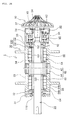
- FIGS. 1 and FIGS. 2 to 6 illustrate a detailed configuration of a waste heat recovery power generation system including a turbine device according to an exemplary embodiment in the present disclosure, and a turbine device 1 according to an exemplary embodiment in the present disclosure.
- the turbine device 1 according to the exemplary embodiment in the present disclosure will first be described with reference to FIGS. 2 to 6 , and the waste heat recovery power generation system 200 including the turbine device of the present disclosure will then be described.
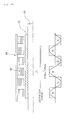
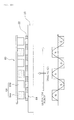
- FIGS. 2A and 2B separately illustrate an electromagnetic bearing 60 provided in a radial direction of a rotary shaft as an apparatus using an electromagnet 62 and an electromagnetic bearing 60 provided in a radial direction of a rotary shaft as an apparatus using a permanent magnet 64, and other constituent elements thereof are the same as one another.
- FIG. 2A will be principally described with respect to constituent elements thereof, and a difference therefrom will be described with reference to constituent elements of FIG. 2B .
- the turbine device 1 may basically include a rotary shaft 20 connected to an impeller 10 to which rotational force is applied from an working fluid, an electricity generation unit 40 connected to the rotary shaft 20 to generate electricity, and a plurality of electromagnetic bearing units arranged in a first direction of the rotary shaft and a second direction of the rotary shaft, different from each other.
- the first direction and the second direction of the rotary shaft which are directions different from each other, may be understood as being a radial direction of the rotary shaft and an axial direction of the rotary shaft.
- the rotary shaft 20 or a roll structure 22 coupled to an outer surface thereof may be used.
- the roll structure 22 described as above may be used only by replacing a roll structure at the time of coupling or maintenance of components relevant thereto, and with respect to an electromagnetic bearing element, in the case of using a magnetic substance, it may be desirable that a roll structure be formed of a magnetic substance other than the magnetic substance of which an overall rotary shaft is formed.
- the roll structure may have a ring shaped structure as viewed from a front side thereof.
- the first direction will be described as a direction limited to a radial direction.
- the electromagnetic bearing unit 60 provided in a radial direction of the rotary shaft to be described in detail below will be described as being 'a radial electromagnetic bearing unit 60', and an electromagnetic bearing unit 80 provided in an axial direction of the rotary shaft will be described as being 'an axial electromagnetic bearing unit 80'.
- the turbine device 1 may employ radial and axial electromagnetic bearing units 60 and 80 therein so as to provide a bearing element supporting a rotary shaft as a non-contact bearing element.
- the turbine device 1 has a characteristic that two radial electromagnetic bearing units 60 and at least one axial electromagnetic bearing unit 80 are arranged therein.
- FIGS. 2A and 2B illustrate the case in which the axial electromagnetic bearing unit 80 is disposed between the radial electromagnetic bearing unit 60 and the impeller 10, the number of installations thereof or the position thereof is not limited to the illustration of FIG. 2 .
- the axial electromagnetic bearing unit 80 may be disposed between the radial electromagnetic bearing units 60.
- the turbine device 1 in the case of the turbine device 1 according to an exemplary embodiment in the present disclosure, at the time of a high speed rotation of the impeller 10 to which the rotational force is applied due to collision of an working fluid therewith, the rotary shaft 20 rotates at a high speed, and when the rotary shaft 20 rotates at a high speed as described above, electricity may be generated by the electricity generation unit 40.
- the radial bearing unit 60 according to an exemplary embodiment in the present disclosure to be described in detail below may stably support the rotation of the rotary shaft in a frictionless manner, and the axial electromagnetic bearing unit 80 may control a change in axial displacement thereof electromagnetically.
- the turbine device of the present disclosure replaces a mechanical contact element such as an existing ball bearing or thrust bearing, stable electricity generation may be obtained even in the case of using a low pressure and low temperature working fluid by reducing limitations of electricity generation commercialization due to friction between existing bearing elements.
- the working fluid used in the turbine device 1 according to the exemplary embodiment in the present disclosure may be a low temperature working fluid in a range of 150 - 300°C, and for example, as the working fluid used in the turbine device 1 of the present disclosure, H 2 , R134a, R245a, n-pentane, general biogas, or the like, having relatively great expansion force even at a low temperature may be used instead of using existing water (liquid).
- the apparatus according to the exemplary embodiment in the present disclosure may use exhaust gas generated by a heating furnace, a sintering furnace, a blast furnace, or the like, which is difficult to be used thorough an existing apparatus, as is, without an additional increase in temperature, or the like. Utilization of energy through the recovery of waste heat may be facilitated.
- Such a low-temperature (low-pressure) working fluid may be used according to the exemplary embodiment in the present disclosure because the radial and axial electromagnetic bearing units 60 and 80 according to the exemplary embodiment in the present disclosure are used, instead of using a mechanical contact bearing element having severe friction according to the related art. Further, friction may not occur. Thus, the low temperature working fluid may be used without the occurrence of an existing temperature differential of 250°C.
- the electricity generation unit 40 in the turbine device 1 of the present disclosure may include a permanent magnet 42 provided on the rotary shaft 20, in detail, a rotator, and a coil 44 provided on an outer side thereof in a housing unit 30, in detail, a stator.
- the permanent magnet 42 may rotate to apply magnetic force to a coil, such that electricity is generated in a commonly known manner.
- the turbine device 1 of the present disclosure may be provided such that the permanent magnets 42 of the electricity generation unit 40 may have a specific structure, and in the electricity generation unit 40 of the present disclosure, a plurality of the permanent magnets 42 may be arranged in a circumferential direction of the rotary shaft 20.
- the permanent magnets 42 of the electricity generation unit 40 may be arranged in a structure in which magnets having different polarities are stacked in at least one of a circumferential direction and a radial direction of the rotary shaft.
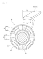
- the permanent magnets 42 may be provided in a manner in which magnets 42a and 42b having different polarities (S-pole, N-pole) are alternately stacked and arranged.
- the permanent magnets may be provided such that appropriate magnet units are continuously provided in a length direction of rotation.
- S-pole magnets 42a and N-pole magnets 42b which are magnet units having an appropriate length in a circumferential direction of the rotary shaft 20, are alternately stacked horizontally (an axial radial direction) and vertically (an axial circumferential direction), and thus, may generate a relatively further increased amount of magnetic force so that electricity generation capability of the coil 44 may be increased as compared to a case in which magnets are simply arranged.
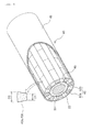
- the permanent magnets 42a and 42b having the same polarity may be alternately arranged in the circumferential direction of the rotary shaft 20, and in this case, although schematically illustrated in the drawing, the magnets may be provided such that magnet units may be mounted on a mounting portion of a drum element 46.
- FIG. 4 illustrates the structure in which the magnet units are continuously provided, a relatively sufficient amount of magnetic force may be generated as compared to a case in which an existing single elongated magnet is used, so that electricity generation capability through a coil may be further increased.
- the permanent magnets of the electricity generation unit 40 may have a quadrilateral structure in which cross sections thereof are increased outwardly in the radial direction of the rotary shaft.
- a magnet unit when a magnet unit has a quadrilateral structure in which an upper width D2 thereof is greater than a bottom width D1 thereof, since an area in which magnetic force is generated is extended in the radial direction, a relatively sufficient amount of magnetic force may be generated.
- the quadrilateral structure of the permanent magnet of FIGS. 3 and 4 may suppress loss of eddy current at the time of rotation of the rotary shaft to increase electricity generation capability.
- FIGS. 5A and 5B illustrate graphs illustrating a degree of generated magnetic force based on the arrangement of the permanent magnets.
- the arrangement of the permanent magnets as illustrated in FIGS. 2A and 4 may be most desirable, but the arrangement of the permanent magnets as illustrated in FIG. 3 may provide sufficient electricity generation capability.
- the permanent magnet 42 when the impeller is rotated by rotational force applied thereto as a working fluid (refrigerant) collides with the impeller 10 and expands, the permanent magnet 42, a stator, may also be rotated integrally, and thus, a time-varying magnetic field generated by the stator may generate an induction current in a steel plate from the coil, a fixed stator, to generate electricity.
- an electromagnetic bearing unit according to an exemplary embodiment in the present disclosure, which supports high-speed rotation of the rotary shaft 20, based on a noncontact and frictionless manner by substantially using (electro)magnetic force in the turbine device 1 of the present disclosure, is illustrated.
- the electromagnetic bearing unit of the turbine device 1 may include a radial electromagnetic bearing unit 60 provided on at least one of a front side and a rear side of the electricity generation unit 40 and supporting the rotary shaft 20 in a noncontact and friction less manner while allowing a gap G1 to be formed between the rotary shaft and the radial electromagnetic bearing unit 60, and an axial electromagnetic bearing unit 80 provided on at least one point of the rotary axis to control displacement of the rotary shaft in an axial direction thereof.
- the axial electromagnetic bearing unit 80 may be provided between disk units 90 provided on the rotary shaft 20, so as to control (prevent) axial displacement of the rotary shaft while allowing a gap G2 to be formed between a bearing unit and a disk unit, through electromagnetic drag force as described below in detail with reference to FIG. 6 .
- the turbine device 1 of the present disclosure may further include the radial electromagnetic bearing unit 60 on the rotary shaft 20, and a roll structure 22, an integral hollow structure, on which the permanent magnet 42 of the electricity generation unit 40 described above is mounted.
- the rotary shaft 20 may be coupled to a connection axis 24 coupled to and combined with the impeller 10, the roll structure 22 having a hollow pipe shape may be coupled outwardly of the rotary shaft 20, and the roll structure 24 described above may be formed using a (ferro)magnetic substance to generate electromagnetic drag force.
- a rotary shaft may be used without using the roll structure 22 described above, and thus, the rotary shaft 20 or the roll structure 22 may be formed using a (ferro)magnetic substance.
- the radial electromagnetic bearing unit 60 of the present disclosure which allows the rotary shaft 20 to be supported in a noncontact and frictionless manner in the turbine device 1 of the present disclosure and allows a low temperature working fluid to be used by replacing an existing mechanical contact bearing element, will be described in detail.
- the radial electromagnetic bearing unit 60 may include an electromagnet 62 generating electromagnetic drag force to form a gap 'G1' between the rotary shaft 20 or the roll structure 22 provided on the rotary shaft, respectively formed using a (ferro)magnetic substance, and the radial electromagnetic bearing unit 60.
- the electromagnet 62 as described above may be arranged on and fixed to an outer side of the rotary shaft through a housing unit 30 described below in detail.
- the electromagnet when a single phase or three phase alternating current is applied to the electromagnet 62 through a pulse width modulator not shown in the drawing, the electromagnet may generate a time-varying magnetic field, and electromagnetic drag force between the electromagnet and the rotary shaft 20 or the roll structure 22 provided on the rotary shaft may be generated. As a result, a predetermined gap 'G1' may be formed between the rotary shaft or the roll structure 22 and the electromagnet, thereby allowing the rotary shaft to be supported in a noncontact frictionless manner, based on magnetic levitation.
- the electromagnets may be provided by stacking appropriate electromagnet units.
- an electromagnet 62 provided on the housing unit 30 side may be provided by stacking ring-shaped electromagnets or electromagnets having a short circuit ring structure (a ring structure) in a circumferential direction of the rotary shaft, as viewed from a front side of the rotary shaft.
- the radial electromagnetic bearing unit 60 may be provided using a permanent magnet.
- the radial electromagnetic bearing unit 60 having another form may be configured of a permanent magnet 64 provided on the rotary shaft 20 or the roll structure 22 provided on the rotary shaft, and an adjacent permanent magnet 64 in which an S pole permanent magnet 64a and an N pole permanent 64b provided on the housing unit 30 side and adjacent to each other are alternately arranged.
- a gap G3 between the permanent magnet 64 on the rotary shaft side and the permanent 64 on the housing unit side may be formed due to magnetic levitation at the time of rotation of the rotary shaft 20, and may support the rotary shaft 20 in a noncontact, frictionless state.
- FIGS. 6A and 6B illustrate the principle of allowing the rotary shaft to be supported in the magnetic levitation manner by the radial electromagnetic bearing unit 60 according to the exemplary embodiment in the present disclosure.
- an induction current may be generated by a time-varying magnetic field in which a magnetic field is changed according to time, and drag force and levitation force may be formed between the electromagnet and the roll structure.
- the drag force for example, the magnetic levitation force, rather than the levitation force, may be formed before reaching a critical rotation speed.
- the permanent magnets 64 may be arranged on the rotary shaft or the roll structure 22, and on surfaces opposed to the rotary shaft or the roll structure, the S pole electromagnet 64a and the N pole electromagnet 64b may be alternately arranged on the housing unit 30 side.
- an induction current may be generated by a time-varying magnetic field in which a magnetic field is changed according to time, and drag force and levitation force may be formed between the permanent magnets.
- the magnetic levitation force may allow for a non-contact frictionless bearing to be formed.
- the axial electromagnetic bearing unit 80 may also include an electromagnet 82.
- a disk unit 90 provided horizontally in a radial direction of a rotary shaft provided on the rotary shaft 20 or a connection shaft 24 via welding or the like may be provided, for example, a first disk 92 provided on the connection shaft 24, and a second disk 94, formed to be perpendicular to the first disk, may be provided.
- the first and second disks may be formed using a magnetic substance.
- the magnetic levitation force may be formed between the first and second disks 92 and 94 to thus form the gap 'G2' therebetween.
- the disk rotates inside the electromagnet, but to maintain the gap in a noncontact scheme, such that with respect to an occurrence of minute displacement in the axial direction of the rotary shaft, displacement in the axial electromagnetic bearing unit may be limited, to control axial displacement.
- FIG. 2 illustrates the housing unit 30 of an apparatus, linked to the rotary shaft 20, or the roll structure 22 provided on the rotary shaft, and the connection shaft 24 connected to the impeller 10 and p rovided to support the radial electromagnetic bearing unit 60 and the axial electromagnetic bearing unit 80 while encompassing the radial electromagnetic bearing unit 60 and the axial electromagnetic bearing unit 80.
- the electromagnet 62 or the permanent magnet 64 of the radial electromagnetic bearing unit 60 provided in a central portion thereof may be fixedly mounted, and a rear-side third housing 32 and a front-side fourth housing 35 may be coupled to both sides of the central first and second housings 33 and 34, with the coil 44 of the stator therebetween, and a rear-side first cap member 31 and a front-side second cap member 34 may be coupled to an outer side thereof, respectively, via bolting, in a sequential manner.
- the electromagnets of the axial electromagnetic bearing unit 80 may be coupled via a bolt or the like, outside the disk unit, in a space between the front-side fourth housing 35 and the second cap member 34.
- fixing rings 38 fixing an electromagnet or a permanent magnet to be coupled thereto may be provided in the housings so as to prevent the separation of the electromagnet or the permanent magnet therefrom.
- the turbine device 1 may further include a sensor unit 130 sensing rotation of the rotary shaft 20.
- the sensor unit 130 may include a first sensor 132 (or sensor unit) provided on the rotary shaft or the roll structure 22 coupled to the rotary shaft, and at an outer side thereof, a sensor unit 134 or a second sensor coupled to inner side surfaces of the third housing 32 and the fourth housing 35.
- the senor when the rotary shaft, or the roll structure 22 formed integrally with the rotary shaft, is rotated, the sensor may also rotate together therewith, and thus, whether or not the rotary shaft is rotated, or a rotation speed thereof, may be sensed in real time, by the sensor unit 130.
- a mechanical contact bearing 110 may be further included so as to support the rotary shaft during a pause in operations of the electromagnetic bearing between the rotary shaft 20 and an apparatus casing 110.
- the mechanical contact bearing 110 may replace rotation of the rotary shaft to perform the support thereby.
- the rotation of the rotary shaft should be supported through the radial electromagnetic bearing unit 60, and thus, the gap 'G1' between the radial electromagnetic bearing unit 60 and the rotary shaft or the roller structure provided on the rotary shaft, or the gap 'G3' between the permanent magnets 64 of the radial electromagnetic bearing unit may be greater than a gap between the mechanical bearing 110, the rotary shaft (a coupling member) and the connection shaft 24.
- the gaps G1 and G3 of the electromagnetic bearing unit side may be in a range of 80 - 200 ⁇ m, and the gap of the mechanical contact bearing 110 side may be in a range of 40 - 70 ⁇ m, so that only during a pause in operations of the electromagnetic bearing, the support of the rotary shaft through the mechanical contact bearing 110 may be implemented.
- the mechanical contact bearing 110 may be provided between a fixing ring (a reference numeral thereof not shown) provided on an end of the roller structure 22 of the rotary shaft 20 and the first cap member 31 of the housing unit 30.
- the gap 'G3' between the permanent magnets 64 of the radial electromagnetic bearing unit 60, based on a permanent magnet, may be within a range of 5 - 200 ⁇ m
- the gap 'G2' between the electromagnet 82 of the axial electromagnetic bearing unit 80 and the first and second disks 92 and 94 of the disk unit 90 may be within a range of about 100 ⁇ 500 ⁇ m.
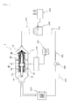
- FIG. 1 illustrates a waste heat recovery power generation system 200 including the turbine device 1 according to an exemplary embodiment in the present disclosure described above.
- electrical power generated by the electricity generation unit 40 of the turbine device 1 may be supplied to sources of demand such as homes 120, industrial facilities, and the like, after dropping a voltage through a power transmitting unit 110, for example, transmission lines and high-voltage substations, voltage substations and pole transformers.
- the turbine device 1 may be provided inside a casing 2 sealed from the external environment, and in the casing 2, an extraction line extracting an expanded working fluid extracted and heated after the generation of electricity with a working fluid supply line may be provided to be linked thereto.
- the waste heat recovery power generation system 200 may be configured to include the turbine device 1 described above, a working fluid supply unit 230 provided to supply a working fluid to the turbine device and using waste heat, and a working fluid processing unit 210 processing the working fluid extracted by the turbine device.
- the working fluid supply unit 230 may be a heater linked to a waste heat supply source 240, for example, a sintering furnace of a steel factory generating high-temperature exhaust gas (waste heat), a blast furnace thereof, or the like
- the working fluid processing unit 210 may be a condenser condensing a low-pressure, low-temperature working fluid extracted by the turbine device 1 of the present disclosure to be heated and expanded, and generating condensed working fluid (refrigerant).
- the waste heat recovery power generation system 200 may be a system recovering a heat source within an approximately low temperature range (60 - 300°C) to thus produce electrical power by a medium of a (low-pressure) low-temperature working fluid.
- the condenser 210 may change a phase of the low temperature working fluid extracted by the turbine device 1 of the present disclosure into a liquid, and the condensed working fluid, condensed through the condenser 210, that is, a refrigerant, may be supplied to the heating furnace 230 through a pump 250.
- a condensation tank 250 and a preheater 260 may be disposed upstream and downstream of the pump, respectively, and a superheater 270 may be disposed between the heater and the turbine device.
- the turbine device may increase electricity generation efficiency while extending the lifespan of a turbine and may facilitate the use of waste heat by replacing a mechanical (contact) bearing structure with a noncontact electromagnetic bearing.
- an apparatus may be stably operated through appropriate disposition of a mechanical bearing unit with structural improvement of a disk unit.
Landscapes
- Engineering & Computer Science (AREA)
- General Engineering & Computer Science (AREA)
- Mechanical Engineering (AREA)
- Chemical & Material Sciences (AREA)
- Combustion & Propulsion (AREA)
- Life Sciences & Earth Sciences (AREA)
- Sustainable Development (AREA)
- Sustainable Energy (AREA)
- Physics & Mathematics (AREA)
- Thermal Sciences (AREA)
- Magnetic Bearings And Hydrostatic Bearings (AREA)
Abstract
Description
- The present disclosure relates to a turbine device, and more particularly, to a turbine device having increased electricity generation efficiency in addition to an increased turbine lifespan which facilitates the use of waste heat by replacing a mechanical (contact) bearing structure with a non-contact-type electronic bearing structure, and further, operating in a stable manner through structural improvements of a disk part and appropriate disposition of a mechanical bearing part, and a waste heat recovery power generation system including the same.
- In general, power plants are classified as hydroelectric power plants, thermoelectric power plants, nuclear power plants, combined cycle power plants, and the like, according to an energy source utilized thereby and an electricity generation method based thereon.
- Recently, research into technology for recovering and reusing waste heat generated in industrial processes by applying such waste heat to power generation systems has been actively undertaken.
- That is, the research into a technology by which waste heat is recovered from high temperature exhaust gas generated in slaked lime processing procedures or from steel plants discharging high temperature exhaust gas and the like from a variety of furnaces, sintering apparatuses, and the like, aimed at applying the technology to electric power generating systems, has been mainly carried out.
- For example, in steel plants, a considerable amount of waste heat is generated in a coke producing process, blast furnace operations, or the like, and in this case, waste heat temperatures range from about 150°C to about 300°C. Here, it may be difficult to apply such a low temperature range to commercialization.
- Meanwhile, although research into a power generation system using a temperature difference of sea water or using waste heat from industrial settings has been conducted, in a case in which water is used as a working fluid for the generation of electricity, a difference in temperature thereof should be equal to or higher than 250°C. Therefore, commercialization thereof may be difficult.
- However, such a temperature differential in working fluid is required because rotary mechanical contact ball bearings or journal bearings are used in the majority of power transfer devices in electricity generation turbine equipment, and further, power is transferred through a screw having a relatively great amount of friction in an axial direction. Thus, power generation efficiency may be deteriorated due to such friction, such that it may be difficult to generate electricity using low temperature waste heat. Therefore, commercialization of such a process using waste heat may be difficult.
- Currently, high temperature exhaust gas generated in steel plants or cement plants is not recycled as waste heat, but mostly discarded.
- For example, Korean Patent Laid-Open Publication No.
2012-0058582 - Further, Korean Patent Laid-Open Publication No.
2006-0010427 - In addition, Japanese Patent Laid-Open Publication No.
2011-083150 - Therefore, in the turbine devices of general power generation equipment, since mechanical contact bearings may be applied to rotors (rotary shafts), a substantial problem as described above is present therein.
- In particular, since such mechanical contact bearings generally use oil (lubricating oil), a problem occurring due to the leakage of oil may occur. Furthermore, since existing systems use steam or high temperature gas, a water hammer phenomenon may occur in the turbine.
- An aspect of the present disclosure may provide a turbine device having an increased lifespan and improved electricity generation efficiency, and able to easily use waste heat by replacing a mechanical (contact) bearing with a noncontact electromagnetic bearing, and stabilizing operations of an apparatus through appropriate disposition of a mechanical bearing with structural improvement of a disk unit, and a waste heat recovery power generation system having the same.
- According to an aspect of the present disclosure, a turbine device may include: a rotary shaft connected to an impeller to which rotational force is applied by a working fluid; an electricity generation unit connected to the rotary shaft to generate electricity; a radial electromagnetic bearing unit provided on at least one of a front side and a rear side of the electricity generation unit to support the rotary shaft in a noncontact manner while allowing a gap to be formed between the rotary shaft and the radial electromagnetic bearing unit; and an axial electromagnetic bearing unit provided on at least one point of the rotary shaft to control displacement of the rotary shaft in an axial direction thereof.
- According to another aspect of the present disclosure, a waste heat recovery power generation system including a turbine device may include: the turbine device described above; a working fluid supply unit provided to supply a working fluid to the turbine device and using waste heat; and a working fluid processing unit processing the working fluid extracted by the turbine device.
- According to an aspect of the present disclosure, by replacing a mechanical contact power transfer device (a bearing, a screw, or the like) in an existing turbine device with a noncontact electromagnetic bearing to remove friction therefrom so as to use a low-pressure, low-temperature working fluid (refrigerant) instead of using a liquid (water), a turbine lifespan may be increased and electricity generation efficiency of the turbine may be significantly improved.
- In detail, axial and radial displacement of a rotary shaft of a turbine device according to an exemplary embodiment in the present disclosure in a radial direction and an axial direction may be precisely controlled through a disk unit linked to the axial electromagnetic bearing unit by a bi-directional structure.
- Further, a turbine device according to an exemplary embodiment in the present disclosure may provide a mechanical bearing unit operating during a pause in operations of an electromagnetic bearing, of which operations may be stably maintained through adjustment of a width of a gap between an electromagnetic bearing unit and a mechanical bearing unit.
- Accordingly, in the case of a power generation system including the turbine device of the present disclosure, a sufficient amount of electricity may be obtained even in the case of using a low-temperature working fluid. Thus, commercialization of existing industrially-generated waste heat is facilitated so that a waste heat recovery rate may be significantly increased.
-
-
FIG. 1 is a configuration diagram illustrating an overall configuration of an power generation system according to an exemplary embodiment in the present disclosure. -
FIGS. 2A and2B are configuration diagrams illustrating a turbine device according to first and second exemplary embodiments of the present disclosure. -
FIGS. 3 and4 are a front view and a partially cutaway perspective view illustrating arrangement of permanent magnets of an electricity generation unit provided in a turbine device according to an exemplary embodiment in the present disclosure. -
FIGS. 5A and 5B are graphs illustrating magnetic force according to an arrangement of permanent magnets of an electricity generation unit illustrated inFIGS. 3 and4 . -
FIGS. 6A and6B are views illustrating the principle of magnetic levitation of an electromagnetic bearing means, based on an electromagnet and a permanent magnet, provided in a turbine device according to an exemplary embodiment in the present disclosure. - Hereinafter, exemplary embodiments of the present disclosure will be described in detail with reference to the accompanying drawings. The disclosure may, however, be exemplified in many different forms and should not be construed as being limited to the specific embodiments set forth herein, and those skilled in the art and understanding the present disclosure can easily accomplish retrogressive inventions or other embodiments included in the scope of the present disclosure by the addition, modification, and removal of components within the same scope, but those are construed as being included in the scope of the present disclosure. Like reference numerals will be used to designate like components having similar functions throughout the drawings within the scope of the present disclosure.
- First,
FIGS. 1 andFIGS. 2 to 6 illustrate a detailed configuration of a waste heat recovery power generation system including a turbine device according to an exemplary embodiment in the present disclosure, and aturbine device 1 according to an exemplary embodiment in the present disclosure. - Thus, the
turbine device 1 according to the exemplary embodiment in the present disclosure will first be described with reference toFIGS. 2 to 6 , and the waste heat recoverypower generation system 200 including the turbine device of the present disclosure will then be described. - Although illustrated in detail below,
FIGS. 2A and2B separately illustrate anelectromagnetic bearing 60 provided in a radial direction of a rotary shaft as an apparatus using anelectromagnet 62 and anelectromagnetic bearing 60 provided in a radial direction of a rotary shaft as an apparatus using apermanent magnet 64, and other constituent elements thereof are the same as one another. - Thus,
FIG. 2A will be principally described with respect to constituent elements thereof, and a difference therefrom will be described with reference to constituent elements ofFIG. 2B . - As illustrated in
FIG. 2A , theturbine device 1 according to the exemplary embodiment in the present disclosure may basically include arotary shaft 20 connected to animpeller 10 to which rotational force is applied from an working fluid, anelectricity generation unit 40 connected to therotary shaft 20 to generate electricity, and a plurality of electromagnetic bearing units arranged in a first direction of the rotary shaft and a second direction of the rotary shaft, different from each other. - Here, according to the exemplary embodiment in the present disclosure, the first direction and the second direction of the rotary shaft, which are directions different from each other, may be understood as being a radial direction of the rotary shaft and an axial direction of the rotary shaft.
- In addition, according to an exemplary embodiment in the present disclosure, the
rotary shaft 20 or aroll structure 22 coupled to an outer surface thereof may be used. Theroll structure 22 described as above may be used only by replacing a roll structure at the time of coupling or maintenance of components relevant thereto, and with respect to an electromagnetic bearing element, in the case of using a magnetic substance, it may be desirable that a roll structure be formed of a magnetic substance other than the magnetic substance of which an overall rotary shaft is formed. - In this case, the roll structure may have a ring shaped structure as viewed from a front side thereof.
- In addition, in the exemplary embodiment of the present disclosure described below, the first direction will be described as a direction limited to a radial direction. The electromagnetic bearing
unit 60 provided in a radial direction of the rotary shaft to be described in detail below will be described as being 'a radial electromagnetic bearing unit 60', and an electromagnetic bearingunit 80 provided in an axial direction of the rotary shaft will be described as being 'an axial electromagnetic bearing unit 80'. - Thus, most existing turbine devices employ mechanical contact-type bearing components to be used in supporting a rotary shaft. Meanwhile, as illustrated in
FIG. 2A , theturbine device 1 according to an exemplary embodiment in the present disclosure may employ radial and axialelectromagnetic bearing units - In detail, the
turbine device 1 according to an exemplary embodiment in the present disclosure has a characteristic that two radialelectromagnetic bearing units 60 and at least one axial electromagnetic bearingunit 80 are arranged therein. - On the other hand, although
FIGS. 2A and2B illustrate the case in which the axialelectromagnetic bearing unit 80 is disposed between the radialelectromagnetic bearing unit 60 and theimpeller 10, the number of installations thereof or the position thereof is not limited to the illustration ofFIG. 2 . For example, the axialelectromagnetic bearing unit 80 may be disposed between the radialelectromagnetic bearing units 60. - However, in a case in which it is desirable to arrange two radial electromagnetic bearing
units 60 and one axialelectromagnetic bearing unit 80, the arrangement ofFIG. 2 may be desirable. - Thus, in the case of the
turbine device 1 according to an exemplary embodiment in the present disclosure, at the time of a high speed rotation of theimpeller 10 to which the rotational force is applied due to collision of an working fluid therewith, therotary shaft 20 rotates at a high speed, and when therotary shaft 20 rotates at a high speed as described above, electricity may be generated by theelectricity generation unit 40. In addition, theradial bearing unit 60 according to an exemplary embodiment in the present disclosure to be described in detail below may stably support the rotation of the rotary shaft in a frictionless manner, and the axialelectromagnetic bearing unit 80 may control a change in axial displacement thereof electromagnetically. - Thus, since the turbine device of the present disclosure replaces a mechanical contact element such as an existing ball bearing or thrust bearing, stable electricity generation may be obtained even in the case of using a low pressure and low temperature working fluid by reducing limitations of electricity generation commercialization due to friction between existing bearing elements.
- In this case, the working fluid used in the
turbine device 1 according to the exemplary embodiment in the present disclosure may be a low temperature working fluid in a range of 150 - 300°C, and for example, as the working fluid used in theturbine device 1 of the present disclosure, H2, R134a, R245a, n-pentane, general biogas, or the like, having relatively great expansion force even at a low temperature may be used instead of using existing water (liquid). - Thus, since the
turbine device 1 according to the exemplary embodiment in the present disclosure is provided to use a low temperature working fluid, considering that 60 % or more of industrial waste heat may be within the temperature range described above, the apparatus according to the exemplary embodiment in the present disclosure may use exhaust gas generated by a heating furnace, a sintering furnace, a blast furnace, or the like, which is difficult to be used thorough an existing apparatus, as is, without an additional increase in temperature, or the like. Utilization of energy through the recovery of waste heat may be facilitated. - Such a low-temperature (low-pressure) working fluid may be used according to the exemplary embodiment in the present disclosure because the radial and axial
electromagnetic bearing units - As a result, extensively generated existing industrial exhaust gas may be used as a heat source as is, and thus, a waste heat recovery rate may be relatively high.
- Next, as illustrated in
FIGS. 2A andFIGS. 3 and4 , theelectricity generation unit 40 in theturbine device 1 of the present disclosure may include apermanent magnet 42 provided on therotary shaft 20, in detail, a rotator, and acoil 44 provided on an outer side thereof in ahousing unit 30, in detail, a stator. - Thus, when the working fluid collides with the
impeller 10 and rotational force is thereby applied to therotary shaft 20 to rotate at a high speed, thepermanent magnet 42 may rotate to apply magnetic force to a coil, such that electricity is generated in a commonly known manner. - In this case, the
turbine device 1 of the present disclosure may be provided such that thepermanent magnets 42 of theelectricity generation unit 40 may have a specific structure, and in theelectricity generation unit 40 of the present disclosure, a plurality of thepermanent magnets 42 may be arranged in a circumferential direction of therotary shaft 20. - In detail, as illustrated in
FIGS. 2A and3 , thepermanent magnets 42 of theelectricity generation unit 40 according to the exemplary embodiment in the present disclosure may be arranged in a structure in which magnets having different polarities are stacked in at least one of a circumferential direction and a radial direction of the rotary shaft. - In further detail, the
permanent magnets 42 may be provided in a manner in whichmagnets - In this case, the permanent magnets may be provided such that appropriate magnet units are continuously provided in a length direction of rotation.
- Thus, as illustrated in
FIG. 3 , in the case of thepermanent magnets 42 of theelectricity generation unit 40 according to the exemplary embodiment in the present disclosure, S-pole magnets 42a and N-pole magnets 42b, which are magnet units having an appropriate length in a circumferential direction of therotary shaft 20, are alternately stacked horizontally (an axial radial direction) and vertically (an axial circumferential direction), and thus, may generate a relatively further increased amount of magnetic force so that electricity generation capability of thecoil 44 may be increased as compared to a case in which magnets are simply arranged. - Alternatively, as illustrated in
FIG. 4 , thepermanent magnets rotary shaft 20, and in this case, although schematically illustrated in the drawing, the magnets may be provided such that magnet units may be mounted on a mounting portion of adrum element 46. - Accordingly, since
FIG. 4 illustrates the structure in which the magnet units are continuously provided, a relatively sufficient amount of magnetic force may be generated as compared to a case in which an existing single elongated magnet is used, so that electricity generation capability through a coil may be further increased. - In further detail, as illustrated in
FIGS. 3 and4 , the permanent magnets of theelectricity generation unit 40 according to the exemplary embodiment in the present disclosure may have a quadrilateral structure in which cross sections thereof are increased outwardly in the radial direction of the rotary shaft. - For example, in the case of a magnet unit, when a magnet unit has a quadrilateral structure in which an upper width D2 thereof is greater than a bottom width D1 thereof, since an area in which magnetic force is generated is extended in the radial direction, a relatively sufficient amount of magnetic force may be generated.
- For example, the quadrilateral structure of the permanent magnet of
FIGS. 3 and4 may suppress loss of eddy current at the time of rotation of the rotary shaft to increase electricity generation capability. - On the other hand, in further detail, the permanent magnets may be formed on the
rotary shaft 20 in the arrangement illustrated inFIG. 4 , and in connection therewith,FIGS. 5A and 5B illustrate graphs illustrating a degree of generated magnetic force based on the arrangement of the permanent magnets. - In detail, as compared to the case of alternately arranging the
permanent magnets FIG. 5A , when thepermanent magnets FIG. 5B , magnetic force generation capability may be significantly increased. Thus, although schematically illustrated inFIG. 2A , in theelectricity generation unit 40 according to the exemplary embodiment in the present disclosure, even in a case in which thepermanent magnet 42 on the rotary shaft (rotator) side and a stator of thecoil 44 are disposed at a greater interval of about 2.5 times an interval of 10mm according to the related art, a sufficient amount of electricity may be generated. - Thus, the arrangement of the permanent magnets as illustrated in
FIGS. 2A and4 may be most desirable, but the arrangement of the permanent magnets as illustrated inFIG. 3 may provide sufficient electricity generation capability. - In further detail, in the case of the
turbine device 1 of the present disclosure, when the impeller is rotated by rotational force applied thereto as a working fluid (refrigerant) collides with theimpeller 10 and expands, thepermanent magnet 42, a stator, may also be rotated integrally, and thus, a time-varying magnetic field generated by the stator may generate an induction current in a steel plate from the coil, a fixed stator, to generate electricity. - In further detail, at the time of rotation of the rotary shaft of a turbine device in the case of the related art, a screw is forcedly rotated in an axial direction to generate line contact and point contact in a radial direction by a ball, a thrust or a roller bearing element. Thus, in the case of the related art, a considerable amount of starting torque is required at an initial stage of electricity generation, and in detail, oil (lubricant) leakage or a water hammer phenomenon occurs in a bearing element to deteriorate maintenance efficiency, and there is also limitation in electricity generation efficiency. However, in the turbine device of the present disclosure, medium, low temperature waste heat reaching 60% of industrial waste heat may be recovered, and thus, a fluid application range may be extended and electricity generation efficiency may be increased.
- As illustrated in
FIGS. 2A ,2B , andFIG. 6 , an electromagnetic bearing unit according to an exemplary embodiment in the present disclosure, which supports high-speed rotation of therotary shaft 20, based on a noncontact and frictionless manner by substantially using (electro)magnetic force in theturbine device 1 of the present disclosure, is illustrated. - In detail, as illustrated in
FIGS. 2A and2B , the electromagnetic bearing unit of theturbine device 1 according to an exemplary embodiment in the present disclosure may include a radialelectromagnetic bearing unit 60 provided on at least one of a front side and a rear side of theelectricity generation unit 40 and supporting therotary shaft 20 in a noncontact and friction less manner while allowing a gap G1 to be formed between the rotary shaft and the radialelectromagnetic bearing unit 60, and an axialelectromagnetic bearing unit 80 provided on at least one point of the rotary axis to control displacement of the rotary shaft in an axial direction thereof. - In detail, the axial
electromagnetic bearing unit 80 according to the exemplary embodiment in the present disclosure may be provided betweendisk units 90 provided on therotary shaft 20, so as to control (prevent) axial displacement of the rotary shaft while allowing a gap G2 to be formed between a bearing unit and a disk unit, through electromagnetic drag force as described below in detail with reference toFIG. 6 . - On the other hand, in more detail, the
turbine device 1 of the present disclosure may further include the radialelectromagnetic bearing unit 60 on therotary shaft 20, and aroll structure 22, an integral hollow structure, on which thepermanent magnet 42 of theelectricity generation unit 40 described above is mounted. - Thus, as illustrated in
FIGS. 2A and2B , in the apparatus of the present disclosure, therotary shaft 20 may be coupled to aconnection axis 24 coupled to and combined with theimpeller 10, theroll structure 22 having a hollow pipe shape may be coupled outwardly of therotary shaft 20, and theroll structure 24 described above may be formed using a (ferro)magnetic substance to generate electromagnetic drag force. - Also, only a rotary shaft may be used without using the
roll structure 22 described above, and thus, therotary shaft 20 or theroll structure 22 may be formed using a (ferro)magnetic substance. - Subsequently, the radial
electromagnetic bearing unit 60 of the present disclosure, which allows therotary shaft 20 to be supported in a noncontact and frictionless manner in theturbine device 1 of the present disclosure and allows a low temperature working fluid to be used by replacing an existing mechanical contact bearing element, will be described in detail. - For example, as illustrated in
FIG. 2A , the radialelectromagnetic bearing unit 60 according to the exemplary embodiment in the present disclosure may include anelectromagnet 62 generating electromagnetic drag force to form a gap 'G1' between therotary shaft 20 or theroll structure 22 provided on the rotary shaft, respectively formed using a (ferro)magnetic substance, and the radialelectromagnetic bearing unit 60. - The
electromagnet 62 as described above may be arranged on and fixed to an outer side of the rotary shaft through ahousing unit 30 described below in detail. - Thus, as illustrated in
FIG. 2A , when a single phase or three phase alternating current is applied to theelectromagnet 62 through a pulse width modulator not shown in the drawing, the electromagnet may generate a time-varying magnetic field, and electromagnetic drag force between the electromagnet and therotary shaft 20 or theroll structure 22 provided on the rotary shaft may be generated. As a result, a predetermined gap 'G1' may be formed between the rotary shaft or theroll structure 22 and the electromagnet, thereby allowing the rotary shaft to be supported in a noncontact frictionless manner, based on magnetic levitation. - On the other hand, the electromagnets may be provided by stacking appropriate electromagnet units.
- Here, although schematically illustrated in
FIG. 2A , anelectromagnet 62 provided on thehousing unit 30 side may be provided by stacking ring-shaped electromagnets or electromagnets having a short circuit ring structure (a ring structure) in a circumferential direction of the rotary shaft, as viewed from a front side of the rotary shaft. - Alternatively, as illustrated in
FIG. 2B , in theturbine device 1 according to the exemplary embodiment in the present disclosure, the radialelectromagnetic bearing unit 60 may be provided using a permanent magnet. - For example, the radial
electromagnetic bearing unit 60 having another form may be configured of apermanent magnet 64 provided on therotary shaft 20 or theroll structure 22 provided on the rotary shaft, and an adjacentpermanent magnet 64 in which an S polepermanent magnet 64a and an N pole permanent 64b provided on thehousing unit 30 side and adjacent to each other are alternately arranged. - Thus, a gap G3 between the
permanent magnet 64 on the rotary shaft side and the permanent 64 on the housing unit side may be formed due to magnetic levitation at the time of rotation of therotary shaft 20, and may support therotary shaft 20 in a noncontact, frictionless state. - On the other hand,
FIGS. 6A and6B illustrate the principle of allowing the rotary shaft to be supported in the magnetic levitation manner by the radialelectromagnetic bearing unit 60 according to the exemplary embodiment in the present disclosure. - In detail, in
FIG. 6A , when a single phase or three phase alternating current is applied to the S pole electromagnet 62a and the N pole electromagnet 62b disposed to have a gap between the electromagnetic bearing unit and theroll structure 22 formed of the (ferro)magnetic substance and coupled to an outer circumferential surface of therotary shaft 20 as described above, an induction current may be generated by a time-varying magnetic field in which a magnetic field is changed according to time, and drag force and levitation force may be formed between the electromagnet and the roll structure. In this case, the drag force, for example, the magnetic levitation force, rather than the levitation force, may be formed before reaching a critical rotation speed. - In addition, as illustrated in
FIG. 6B , thepermanent magnets 64 may be arranged on the rotary shaft or theroll structure 22, and on surfaces opposed to the rotary shaft or the roll structure, theS pole electromagnet 64a and theN pole electromagnet 64b may be alternately arranged on thehousing unit 30 side. In this case, at the time of rotation of the rotary shaft, an induction current may be generated by a time-varying magnetic field in which a magnetic field is changed according to time, and drag force and levitation force may be formed between the permanent magnets. Thus, the magnetic levitation force may allow for a non-contact frictionless bearing to be formed. - Subsequently, as illustrated in
FIGS. 2A and2B , although schematically illustrated in the drawings, in a manner similar to that of the radialelectromagnetic bearing unit 60, the axialelectromagnetic bearing unit 80 according to the exemplary embodiment in the present disclosure may also include anelectromagnet 82. On an inner side of the axialelectromagnetic bearing unit 80 of the electromagnet described above, adisk unit 90 provided horizontally in a radial direction of a rotary shaft provided on therotary shaft 20 or aconnection shaft 24 via welding or the like may be provided, for example, afirst disk 92 provided on theconnection shaft 24, and asecond disk 94, formed to be perpendicular to the first disk, may be provided. - Here, the first and second disks may be formed using a magnetic substance.
- Thus, as illustrated in
FIGS. 2A and2B , when a single phase or three phase alternating current is applied to theelectromagnet 82 configuring the axialelectromagnetic bearing unit 80 from a pulse width modulator, as the radialelectromagnetic bearing unit 60 has been sufficiently described above, the magnetic levitation force may be formed between the first andsecond disks - Next, as described above with respect to the
turbine device 1 according to the exemplary embodiment in the present disclosure,FIG. 2 illustrates thehousing unit 30 of an apparatus, linked to therotary shaft 20, or theroll structure 22 provided on the rotary shaft, and theconnection shaft 24 connected to theimpeller 10 and p rovided to support the radialelectromagnetic bearing unit 60 and the axialelectromagnetic bearing unit 80 while encompassing the radialelectromagnetic bearing unit 60 and the axialelectromagnetic bearing unit 80. - In detail, as illustrated in
FIG. 2 , in thehousing unit 30 of the present disclosure, theelectromagnet 62 or thepermanent magnet 64 of the radialelectromagnetic bearing unit 60 provided in a central portion thereof may be fixedly mounted, and a rear-sidethird housing 32 and a front-sidefourth housing 35 may be coupled to both sides of the central first andsecond housings coil 44 of the stator therebetween, and a rear-sidefirst cap member 31 and a front-sidesecond cap member 34 may be coupled to an outer side thereof, respectively, via bolting, in a sequential manner. - In addition, the electromagnets of the axial
electromagnetic bearing unit 80 may be coupled via a bolt or the like, outside the disk unit, in a space between the front-sidefourth housing 35 and thesecond cap member 34. - In addition, fixing rings 38 fixing an electromagnet or a permanent magnet to be coupled thereto may be provided in the housings so as to prevent the separation of the electromagnet or the permanent magnet therefrom.
- Then, the
turbine device 1 according to the exemplary embodiment in the present disclosure may further include asensor unit 130 sensing rotation of therotary shaft 20. For example, thesensor unit 130 may include a first sensor 132 (or sensor unit) provided on the rotary shaft or theroll structure 22 coupled to the rotary shaft, and at an outer side thereof, asensor unit 134 or a second sensor coupled to inner side surfaces of thethird housing 32 and thefourth housing 35. - Thus, when the rotary shaft, or the
roll structure 22 formed integrally with the rotary shaft, is rotated, the sensor may also rotate together therewith, and thus, whether or not the rotary shaft is rotated, or a rotation speed thereof, may be sensed in real time, by thesensor unit 130. - Subsequently, as illustrated in
FIGS. 2A and2B , a mechanical contact bearing 110 may be further included so as to support the rotary shaft during a pause in operations of the electromagnetic bearing between therotary shaft 20 and anapparatus casing 110. - In the
electromagnetic bearing units - However, in the case of normal electricity generation, for example, when an alternating current is normally applied, the rotation of the rotary shaft should be supported through the radial
electromagnetic bearing unit 60, and thus, the gap 'G1' between the radialelectromagnetic bearing unit 60 and the rotary shaft or the roller structure provided on the rotary shaft, or the gap 'G3' between thepermanent magnets 64 of the radial electromagnetic bearing unit may be greater than a gap between themechanical bearing 110, the rotary shaft (a coupling member) and theconnection shaft 24. - For example, the gaps G1 and G3 of the electromagnetic bearing unit side may be in a range of 80 - 200µm, and the gap of the mechanical contact bearing 110 side may be in a range of 40 - 70µm, so that only during a pause in operations of the electromagnetic bearing, the support of the rotary shaft through the mechanical contact bearing 110 may be implemented.
- Here, although not shown as a separate reference numeral in
FIGS. 2A and2B , the mechanical contact bearing 110 may be provided between a fixing ring (a reference numeral thereof not shown) provided on an end of theroller structure 22 of therotary shaft 20 and thefirst cap member 31 of thehousing unit 30. - For example, as illustrated in
FIG. 2B , the gap 'G3' between thepermanent magnets 64 of the radialelectromagnetic bearing unit 60, based on a permanent magnet, may be within a range of 5 - 200µm, and the gap 'G2' between theelectromagnet 82 of the axialelectromagnetic bearing unit 80 and the first andsecond disks disk unit 90 may be within a range of about 100~ 500µm. - Next,
FIG. 1 illustrates a waste heat recoverypower generation system 200 including theturbine device 1 according to an exemplary embodiment in the present disclosure described above. - First, electrical power generated by the
electricity generation unit 40 of theturbine device 1 according to the exemplary embodiment in the present disclosure may be supplied to sources of demand such ashomes 120, industrial facilities, and the like, after dropping a voltage through apower transmitting unit 110, for example, transmission lines and high-voltage substations, voltage substations and pole transformers. - In addition, as illustrated in
FIG. 1 , theturbine device 1 according to the exemplary embodiment in the present disclosure may be provided inside acasing 2 sealed from the external environment, and in thecasing 2, an extraction line extracting an expanded working fluid extracted and heated after the generation of electricity with a working fluid supply line may be provided to be linked thereto. - Thus, the waste heat recovery
power generation system 200 according to an exemplary embodiment in the present disclosure may be configured to include theturbine device 1 described above, a workingfluid supply unit 230 provided to supply a working fluid to the turbine device and using waste heat, and a workingfluid processing unit 210 processing the working fluid extracted by the turbine device. - Here, in detail, the working
fluid supply unit 230 according to the exemplary embodiment in the present disclosure may be a heater linked to a wasteheat supply source 240, for example, a sintering furnace of a steel factory generating high-temperature exhaust gas (waste heat), a blast furnace thereof, or the like, and the workingfluid processing unit 210 may be a condenser condensing a low-pressure, low-temperature working fluid extracted by theturbine device 1 of the present disclosure to be heated and expanded, and generating condensed working fluid (refrigerant). - Thus, as described above, the waste heat recovery
power generation system 200 may be a system recovering a heat source within an approximately low temperature range (60 - 300°C) to thus produce electrical power by a medium of a (low-pressure) low-temperature working fluid. - Further, the
condenser 210 may change a phase of the low temperature working fluid extracted by theturbine device 1 of the present disclosure into a liquid, and the condensed working fluid, condensed through thecondenser 210, that is, a refrigerant, may be supplied to theheating furnace 230 through apump 250. Here, acondensation tank 250 and apreheater 260 may be disposed upstream and downstream of the pump, respectively, and asuperheater 270 may be disposed between the heater and the turbine device. - Accordingly, the turbine device according to an exemplary embodiment in the present disclosure and an power generation system including the same described above may increase electricity generation efficiency while extending the lifespan of a turbine and may facilitate the use of waste heat by replacing a mechanical (contact) bearing structure with a noncontact electromagnetic bearing. In addition, an apparatus may be stably operated through appropriate disposition of a mechanical bearing unit with structural improvement of a disk unit.
- While exemplary embodiments have been shown and described above, it will be apparent to those skilled in the art that modifications and variations could be made without departing from the scope of the present invention as defined by the appended claims.
Claims (12)
- A turbine device comprising:a rotary shaft connected to an impeller to which rotational force is applied by a working fluid;an electricity generation unit connected to the rotary shaft to generate electricity;a radial electromagnetic bearing unit provided on at least one of a front side and a rear side of the electricity generation unit to support the rotary shaft in a noncontact manner while allowing a gap to be formed between the rotary shaft and the radial electromagnetic bearing unit; andan axial electromagnetic bearing unit provided on at least one point of the rotary shaft to control displacement of the rotary shaft in an axial direction.
- The turbine device of claim 1, wherein the axial electromagnetic bearing unit is provided to control the axial displacement while allowing a gap to be formed between disk units provided on the rotary shaft.
- The turbine device of claim 2, wherein the disk unit comprises a first disk provided on the rotary shaft or a connection shaft connected to a rotary body together with the impeller to be coupled to each other in a radial direction of the rotary shaft, and a second disk provided with the first disk in the axial direction of the rotary shaft.
- The turbine device of claim 1, wherein the electricity generation unit comprises a rotator including a permanent magnet provided on the rotary shaft, and a stator including a coil arranged on an outer side thereof, and the permanent magnet of the electricity generation unit is characterized in that magnets having different polarities are alternately arranged along the rotary shaft while being stacked in a circumferential direction and a radial direction of the rotary shaft, or the magnets having different polarities are disposed at an interval.
- The turbine device of claim 4, wherein the permanent magnet provided as the rotator of the electricity generation unit has a quadrilateral structure in which cross sections thereof are increased outwardly in the radial direction of the rotary shaft.
- The turbine device of claim 1, wherein the radial electromagnetic bearing unit comprises an electromagnet provided to allow magnetic levitation to occur, to form a gap between the radial electromagnetic bearing unit and the rotary shaft formed using a magnetic substance or a roll structure provided on the rotary shaft, and
the axial electromagnetic bearing unit comprises an electromagnet provided to allow magnetic levitation to occur to form a gap between disk units provided on the rotary shaft formed using a magnetic substance. - The turbine device of claim 1, wherein the radial electromagnetic bearing unit comprises a permanent magnet provided on the radial shaft or a roll structure provided on the rotary shaft, and adjacent permanent magnets provided to form a gap between the permanent magnet and the adjacent permanent magnets.
- The turbine device of claim 1, further comprising an apparatus housing unit linked to the roll structure provided on the rotary shaft to support electromagnetic bearing units while encompassing the electromagnetic bearing units.
- The turbine device of claim 8, further comprising a mechanical contact bearing disposed between the rotary shaft and the apparatus housing unit to support the rotary shaft during a pause in operations of the electromagnetic bearing unit.
- The turbine device of claim 9, wherein a gap between the radial electromagnetic bearing unit and the rotary shaft or the roll structure provided on the rotary shaft, or a gap between permanent magnets provided on the radial electromagnetic bearing unit is greater than a gap with the mechanical contact bearing, to operate the mechanical contact bearing during a pause in operations of the electromagnetic bearing unit.
- The turbine device of claim 1, further comprising a sensor unit provided to sense rotation of the rotary shaft.
- A waste heat recovery power generation system including a turbine device, comprising:the turbine device of any one of claims 1 to 11;a working fluid supply unit provided to supply a working fluid to the turbine device and using waste heat; anda working fluid processing unit processing the working fluid extracted by the turbine device.
Applications Claiming Priority (2)
| Application Number | Priority Date | Filing Date | Title |
|---|---|---|---|
| KR1020120154351A KR101403195B1 (en) | 2012-12-27 | 2012-12-27 | Turbine apparatus and waste heat recovery generation system having the same |
| PCT/KR2013/011941 WO2014104659A1 (en) | 2012-12-27 | 2013-12-20 | Turbine device, and waste heat recovery power generation system including same |
Publications (3)
| Publication Number | Publication Date |
|---|---|
| EP2940258A1 true EP2940258A1 (en) | 2015-11-04 |
| EP2940258A4 EP2940258A4 (en) | 2016-01-13 |
| EP2940258B1 EP2940258B1 (en) | 2018-11-28 |
Family
ID=51021640
Family Applications (1)
| Application Number | Title | Priority Date | Filing Date |
|---|---|---|---|
| EP13868327.1A Active EP2940258B1 (en) | 2012-12-27 | 2013-12-20 | Turbine device, and waste heat recovery power generation system including same |
Country Status (4)
| Country | Link |
|---|---|
| EP (1) | EP2940258B1 (en) |
| KR (1) | KR101403195B1 (en) |
| CN (1) | CN104884748B (en) |
| WO (1) | WO2014104659A1 (en) |
Families Citing this family (10)
| Publication number | Priority date | Publication date | Assignee | Title |
|---|---|---|---|---|
| DE102014224285A1 (en) * | 2014-11-27 | 2016-06-02 | Robert Bosch Gmbh | Compressor with a sealing channel |
| KR101672695B1 (en) * | 2015-12-24 | 2016-11-04 | 주식회사 포스코 | Furnace power generator turbine comprising rotatible inner casing |
| DE102016200628A1 (en) * | 2016-01-19 | 2017-07-20 | Robert Bosch Gmbh | Shaft-hub-connection |
| CN105756760B (en) * | 2016-04-21 | 2018-03-09 | 士林电机(苏州)电力设备有限公司 | A kind of generator to be generated electricity using waste gas |
| WO2018111422A1 (en) | 2016-12-15 | 2018-06-21 | Ge Aviation Systems Llc | Air turbine starter with decoupler |
| CN106870032A (en) * | 2017-04-10 | 2017-06-20 | 安徽誉特双节能技术有限公司 | Heat accumulating type steam turbine |
| KR101963534B1 (en) * | 2018-07-06 | 2019-07-31 | 진정홍 | Power generation system for ORC |
| CN110671165B (en) * | 2019-11-13 | 2024-08-20 | 重庆江增船舶重工有限公司 | Expansion power generation integrated high-speed expander |
| CN113830489A (en) * | 2021-09-07 | 2021-12-24 | 曹昌海 | Slay pipeline is with preventing connecting device that splits |
| KR102711293B1 (en) * | 2022-04-12 | 2024-09-30 | 한국가스공사 | Eddy current heater apparatus |
Family Cites Families (17)
| Publication number | Priority date | Publication date | Assignee | Title |
|---|---|---|---|---|
| FR2463444A1 (en) * | 1979-08-06 | 1981-02-20 | Aerospatiale | ALTERNATIVE STATOR PIVOTING DEVICE AND ROTOR FOR SATELLITE |
| JPH01268446A (en) * | 1988-04-19 | 1989-10-26 | Toshiba Corp | Claw-pawl type synchronous generator |
| JPH08218816A (en) * | 1995-02-16 | 1996-08-27 | Mitsubishi Heavy Ind Ltd | Low temperature power generation device |
| US6608418B2 (en) * | 2001-08-24 | 2003-08-19 | Smiths Aerospace, Inc. | Permanent magnet turbo-generator having magnetic bearings |
| KR101091894B1 (en) | 2004-07-28 | 2011-12-12 | 삼성테크윈 주식회사 | Gas turbine apparatus improved cooling performance |
| ES2397526T3 (en) * | 2006-09-12 | 2013-03-07 | Cryostar Sas | Energy recovery machine |
| JP2008175293A (en) * | 2007-01-18 | 2008-07-31 | Jtekt Corp | Magnetic bearing device |
| DE102007028905B3 (en) * | 2007-06-22 | 2008-12-11 | Siemens Ag | Bearing device for non-contact mounting of a rotor against a stator |
| DE102007032933B4 (en) * | 2007-07-14 | 2015-02-19 | Atlas Copco Energas Gmbh | turbomachinery |
| EP2290241A1 (en) * | 2009-07-13 | 2011-03-02 | Siemens Aktiengesellschaft | Turbocompressor assembly with a cooling system |
| JP4926225B2 (en) | 2009-10-09 | 2012-05-09 | 株式会社群商 | Accelerator generator |
| JP2011085223A (en) * | 2009-10-16 | 2011-04-28 | Hokkaido Univ | Triaxial active control type magnetic bearing and rotary machine using the same |
| DE102009053102B4 (en) * | 2009-11-13 | 2013-03-28 | Continental Automotive Gmbh | Turbocharger having a thrust bearing arrangement for a shaft of the turbocharger |
| JP2011106302A (en) | 2009-11-13 | 2011-06-02 | Mitsubishi Heavy Ind Ltd | Engine waste heat recovery power-generating turbo system and reciprocating engine system including the same |
| CN102305242B (en) * | 2011-08-15 | 2013-03-13 | 江苏大学 | Radial-axial three-degree-of-freedom alternating current-direct current hybrid magnetic bearing |
| CN202326729U (en) * | 2011-11-16 | 2012-07-11 | 比普络株式会社 | Magnetic bearing with permanent magnets |
| CN102562800A (en) * | 2012-02-28 | 2012-07-11 | 南京化工职业技术学院 | Permanent-magnet-biased axial magnetic bearing |
-
2012
- 2012-12-27 KR KR1020120154351A patent/KR101403195B1/en active Active
-
2013
- 2013-12-20 CN CN201380068789.8A patent/CN104884748B/en active Active
- 2013-12-20 EP EP13868327.1A patent/EP2940258B1/en active Active
- 2013-12-20 WO PCT/KR2013/011941 patent/WO2014104659A1/en not_active Ceased
Also Published As
| Publication number | Publication date |
|---|---|
| EP2940258B1 (en) | 2018-11-28 |
| CN104884748A (en) | 2015-09-02 |
| KR101403195B1 (en) | 2014-06-02 |
| WO2014104659A1 (en) | 2014-07-03 |
| EP2940258A4 (en) | 2016-01-13 |
| CN104884748B (en) | 2016-08-17 |
Similar Documents
| Publication | Publication Date | Title |
|---|---|---|
| EP2940258B1 (en) | Turbine device, and waste heat recovery power generation system including same | |
| US10340768B2 (en) | Flywheel energy storage device with induction torque transfer | |
| EP3217521B1 (en) | Eddy current type heating device | |
| US10701768B2 (en) | Eddy current heat generating apparatus | |
| EP2695282B1 (en) | A mechanical assembly for maintaining an air gap between a stator and rotor in an electro-mechanical energy converter | |
| CN106300851A (en) | air gap control system and method | |
| KR20160139674A (en) | Power generation apparatus using turbo expander of NG supply pipeline | |
| EP3264576A1 (en) | Eddy-current heater | |
| CN203071793U (en) | Non-contact coupling | |
| NO20130127A1 (en) | Method and apparatus for hybrid suspension system | |
| CN101976991A (en) | Rotor system of electromagnetic high-temperature superconductivity magnetic bearing | |
| JP2011129433A (en) | Induction heating device and power generation system equipped with the same | |
| CN102570926A (en) | Five-degree-of-freedom suspended electric power generation system | |
| JP2021527775A (en) | Compact Rankin turbo generator for thermoelectric distributed cogeneration | |
| EP2477311B1 (en) | Generator, in particular for a wind turbine | |
| JP5293626B2 (en) | Induction heating apparatus and power generation system including the same | |
| KR101776435B1 (en) | Eddy Current Heater for Natural gas | |
| JP2017010698A (en) | Induction heating apparatus and power generation system | |
| JP6468126B2 (en) | Eddy current heating device | |
| EP4064790B1 (en) | Heating system, use of a heating system, turbine, and method for heating | |
| KR20210038115A (en) | Magnetic bearing for turbo machine using a high density fluid | |
| CN121906890A (en) | A flywheel energy storage system and its working method | |
| CN103291748A (en) | Magnetic bearing structure | |
| JP2011216421A (en) | Induction heating device and power generation system including the same | |
| CN116667583A (en) | Universal shaded pole type magnetic bearing and implementation method thereof |
Legal Events
| Date | Code | Title | Description |
|---|---|---|---|
| PUAI | Public reference made under article 153(3) epc to a published international application that has entered the european phase |
Free format text: ORIGINAL CODE: 0009012 |
|
| 17P | Request for examination filed |
Effective date: 20150724 |
|
| AK | Designated contracting states |
Kind code of ref document: A1 Designated state(s): AL AT BE BG CH CY CZ DE DK EE ES FI FR GB GR HR HU IE IS IT LI LT LU LV MC MK MT NL NO PL PT RO RS SE SI SK SM TR |
|
| AX | Request for extension of the european patent |
Extension state: BA ME |
|
| A4 | Supplementary search report drawn up and despatched |
Effective date: 20151210 |
|
| RIC1 | Information provided on ipc code assigned before grant |
Ipc: F01D 15/10 20060101ALI20151204BHEP Ipc: F01K 25/10 20060101AFI20151204BHEP Ipc: F16C 32/04 20060101ALI20151204BHEP Ipc: F01D 25/16 20060101ALI20151204BHEP Ipc: F01K 7/16 20060101ALI20151204BHEP Ipc: F01K 13/00 20060101ALI20151204BHEP |
|
| DAX | Request for extension of the european patent (deleted) | ||
| GRAP | Despatch of communication of intention to grant a patent |
Free format text: ORIGINAL CODE: EPIDOSNIGR1 |
|
| STAA | Information on the status of an ep patent application or granted ep patent |
Free format text: STATUS: GRANT OF PATENT IS INTENDED |
|
| RIC1 | Information provided on ipc code assigned before grant |
Ipc: F22B 1/18 20060101ALI20180525BHEP Ipc: F01D 25/16 20060101ALI20180525BHEP Ipc: F01K 13/00 20060101ALI20180525BHEP Ipc: F01K 25/10 20060101AFI20180525BHEP Ipc: F01D 15/10 20060101ALI20180525BHEP Ipc: F16C 32/04 20060101ALI20180525BHEP Ipc: F01K 7/16 20060101ALI20180525BHEP |
|
| INTG | Intention to grant announced |
Effective date: 20180626 |
|
| GRAS | Grant fee paid |
Free format text: ORIGINAL CODE: EPIDOSNIGR3 |
|
| GRAA | (expected) grant |
Free format text: ORIGINAL CODE: 0009210 |
|
| STAA | Information on the status of an ep patent application or granted ep patent |
Free format text: STATUS: THE PATENT HAS BEEN GRANTED |
|
| AK | Designated contracting states |
Kind code of ref document: B1 Designated state(s): AL AT BE BG CH CY CZ DE DK EE ES FI FR GB GR HR HU IE IS IT LI LT LU LV MC MK MT NL NO PL PT RO RS SE SI SK SM TR |
|
| RAP1 | Party data changed (applicant data changed or rights of an application transferred) |
Owner name: POSCO |
|
| REG | Reference to a national code |
Ref country code: CH Ref legal event code: EP |
|
| REG | Reference to a national code |
Ref country code: AT Ref legal event code: REF Ref document number: 1070498 Country of ref document: AT Kind code of ref document: T Effective date: 20181215 |
|
| REG | Reference to a national code |
Ref country code: DE Ref legal event code: R096 Ref document number: 602013047617 Country of ref document: DE |
|
| REG | Reference to a national code |
Ref country code: IE Ref legal event code: FG4D |
|
| REG | Reference to a national code |
Ref country code: NL Ref legal event code: MP Effective date: 20181128 |
|
| REG | Reference to a national code |
Ref country code: LT Ref legal event code: MG4D |
|
| REG | Reference to a national code |
Ref country code: AT Ref legal event code: MK05 Ref document number: 1070498 Country of ref document: AT Kind code of ref document: T Effective date: 20181128 |
|
| PG25 | Lapsed in a contracting state [announced via postgrant information from national office to epo] |
Ref country code: ES Free format text: LAPSE BECAUSE OF FAILURE TO SUBMIT A TRANSLATION OF THE DESCRIPTION OR TO PAY THE FEE WITHIN THE PRESCRIBED TIME-LIMIT Effective date: 20181128 Ref country code: LV Free format text: LAPSE BECAUSE OF FAILURE TO SUBMIT A TRANSLATION OF THE DESCRIPTION OR TO PAY THE FEE WITHIN THE PRESCRIBED TIME-LIMIT Effective date: 20181128 Ref country code: HR Free format text: LAPSE BECAUSE OF FAILURE TO SUBMIT A TRANSLATION OF THE DESCRIPTION OR TO PAY THE FEE WITHIN THE PRESCRIBED TIME-LIMIT Effective date: 20181128 Ref country code: LT Free format text: LAPSE BECAUSE OF FAILURE TO SUBMIT A TRANSLATION OF THE DESCRIPTION OR TO PAY THE FEE WITHIN THE PRESCRIBED TIME-LIMIT Effective date: 20181128 Ref country code: BG Free format text: LAPSE BECAUSE OF FAILURE TO SUBMIT A TRANSLATION OF THE DESCRIPTION OR TO PAY THE FEE WITHIN THE PRESCRIBED TIME-LIMIT Effective date: 20190228 Ref country code: FI Free format text: LAPSE BECAUSE OF FAILURE TO SUBMIT A TRANSLATION OF THE DESCRIPTION OR TO PAY THE FEE WITHIN THE PRESCRIBED TIME-LIMIT Effective date: 20181128 Ref country code: IS Free format text: LAPSE BECAUSE OF FAILURE TO SUBMIT A TRANSLATION OF THE DESCRIPTION OR TO PAY THE FEE WITHIN THE PRESCRIBED TIME-LIMIT Effective date: 20190328 Ref country code: NO Free format text: LAPSE BECAUSE OF FAILURE TO SUBMIT A TRANSLATION OF THE DESCRIPTION OR TO PAY THE FEE WITHIN THE PRESCRIBED TIME-LIMIT Effective date: 20190228 Ref country code: AT Free format text: LAPSE BECAUSE OF FAILURE TO SUBMIT A TRANSLATION OF THE DESCRIPTION OR TO PAY THE FEE WITHIN THE PRESCRIBED TIME-LIMIT Effective date: 20181128 |
|
| PG25 | Lapsed in a contracting state [announced via postgrant information from national office to epo] |
Ref country code: RS Free format text: LAPSE BECAUSE OF FAILURE TO SUBMIT A TRANSLATION OF THE DESCRIPTION OR TO PAY THE FEE WITHIN THE PRESCRIBED TIME-LIMIT Effective date: 20181128 Ref country code: SE Free format text: LAPSE BECAUSE OF FAILURE TO SUBMIT A TRANSLATION OF THE DESCRIPTION OR TO PAY THE FEE WITHIN THE PRESCRIBED TIME-LIMIT Effective date: 20181128 Ref country code: AL Free format text: LAPSE BECAUSE OF FAILURE TO SUBMIT A TRANSLATION OF THE DESCRIPTION OR TO PAY THE FEE WITHIN THE PRESCRIBED TIME-LIMIT Effective date: 20181128 Ref country code: GR Free format text: LAPSE BECAUSE OF FAILURE TO SUBMIT A TRANSLATION OF THE DESCRIPTION OR TO PAY THE FEE WITHIN THE PRESCRIBED TIME-LIMIT Effective date: 20190301 Ref country code: PT Free format text: LAPSE BECAUSE OF FAILURE TO SUBMIT A TRANSLATION OF THE DESCRIPTION OR TO PAY THE FEE WITHIN THE PRESCRIBED TIME-LIMIT Effective date: 20190328 |
|
| PG25 | Lapsed in a contracting state [announced via postgrant information from national office to epo] |
Ref country code: NL Free format text: LAPSE BECAUSE OF FAILURE TO SUBMIT A TRANSLATION OF THE DESCRIPTION OR TO PAY THE FEE WITHIN THE PRESCRIBED TIME-LIMIT Effective date: 20181128 |
|
| PG25 | Lapsed in a contracting state [announced via postgrant information from national office to epo] |
Ref country code: IT Free format text: LAPSE BECAUSE OF FAILURE TO SUBMIT A TRANSLATION OF THE DESCRIPTION OR TO PAY THE FEE WITHIN THE PRESCRIBED TIME-LIMIT Effective date: 20181128 Ref country code: DK Free format text: LAPSE BECAUSE OF FAILURE TO SUBMIT A TRANSLATION OF THE DESCRIPTION OR TO PAY THE FEE WITHIN THE PRESCRIBED TIME-LIMIT Effective date: 20181128 Ref country code: PL Free format text: LAPSE BECAUSE OF FAILURE TO SUBMIT A TRANSLATION OF THE DESCRIPTION OR TO PAY THE FEE WITHIN THE PRESCRIBED TIME-LIMIT Effective date: 20181128 Ref country code: CZ Free format text: LAPSE BECAUSE OF FAILURE TO SUBMIT A TRANSLATION OF THE DESCRIPTION OR TO PAY THE FEE WITHIN THE PRESCRIBED TIME-LIMIT Effective date: 20181128 |
|
| REG | Reference to a national code |
Ref country code: CH Ref legal event code: PL |
|
| REG | Reference to a national code |
Ref country code: DE Ref legal event code: R097 Ref document number: 602013047617 Country of ref document: DE |
|
| PG25 | Lapsed in a contracting state [announced via postgrant information from national office to epo] |
Ref country code: LU Free format text: LAPSE BECAUSE OF NON-PAYMENT OF DUE FEES Effective date: 20181220 Ref country code: SK Free format text: LAPSE BECAUSE OF FAILURE TO SUBMIT A TRANSLATION OF THE DESCRIPTION OR TO PAY THE FEE WITHIN THE PRESCRIBED TIME-LIMIT Effective date: 20181128 Ref country code: RO Free format text: LAPSE BECAUSE OF FAILURE TO SUBMIT A TRANSLATION OF THE DESCRIPTION OR TO PAY THE FEE WITHIN THE PRESCRIBED TIME-LIMIT Effective date: 20181128 Ref country code: MC Free format text: LAPSE BECAUSE OF FAILURE TO SUBMIT A TRANSLATION OF THE DESCRIPTION OR TO PAY THE FEE WITHIN THE PRESCRIBED TIME-LIMIT Effective date: 20181128 Ref country code: EE Free format text: LAPSE BECAUSE OF FAILURE TO SUBMIT A TRANSLATION OF THE DESCRIPTION OR TO PAY THE FEE WITHIN THE PRESCRIBED TIME-LIMIT Effective date: 20181128 Ref country code: SM Free format text: LAPSE BECAUSE OF FAILURE TO SUBMIT A TRANSLATION OF THE DESCRIPTION OR TO PAY THE FEE WITHIN THE PRESCRIBED TIME-LIMIT Effective date: 20181128 |
|
| REG | Reference to a national code |
Ref country code: IE Ref legal event code: MM4A |
|
| REG | Reference to a national code |
Ref country code: BE Ref legal event code: MM Effective date: 20181231 |
|
| PLBE | No opposition filed within time limit |
Free format text: ORIGINAL CODE: 0009261 |
|
| STAA | Information on the status of an ep patent application or granted ep patent |
Free format text: STATUS: NO OPPOSITION FILED WITHIN TIME LIMIT |
|
| PG25 | Lapsed in a contracting state [announced via postgrant information from national office to epo] |
Ref country code: SI Free format text: LAPSE BECAUSE OF FAILURE TO SUBMIT A TRANSLATION OF THE DESCRIPTION OR TO PAY THE FEE WITHIN THE PRESCRIBED TIME-LIMIT Effective date: 20181128 Ref country code: IE Free format text: LAPSE BECAUSE OF NON-PAYMENT OF DUE FEES Effective date: 20181220 |
|
| 26N | No opposition filed |
Effective date: 20190829 |
|
| PG25 | Lapsed in a contracting state [announced via postgrant information from national office to epo] |
Ref country code: BE Free format text: LAPSE BECAUSE OF NON-PAYMENT OF DUE FEES Effective date: 20181231 |
|
| PG25 | Lapsed in a contracting state [announced via postgrant information from national office to epo] |
Ref country code: LI Free format text: LAPSE BECAUSE OF NON-PAYMENT OF DUE FEES Effective date: 20181231 Ref country code: CH Free format text: LAPSE BECAUSE OF NON-PAYMENT OF DUE FEES Effective date: 20181231 |
|
| PG25 | Lapsed in a contracting state [announced via postgrant information from national office to epo] |
Ref country code: MT Free format text: LAPSE BECAUSE OF NON-PAYMENT OF DUE FEES Effective date: 20181220 |
|
| PG25 | Lapsed in a contracting state [announced via postgrant information from national office to epo] |
Ref country code: TR Free format text: LAPSE BECAUSE OF FAILURE TO SUBMIT A TRANSLATION OF THE DESCRIPTION OR TO PAY THE FEE WITHIN THE PRESCRIBED TIME-LIMIT Effective date: 20181128 |
|
| PG25 | Lapsed in a contracting state [announced via postgrant information from national office to epo] |
Ref country code: HU Free format text: LAPSE BECAUSE OF FAILURE TO SUBMIT A TRANSLATION OF THE DESCRIPTION OR TO PAY THE FEE WITHIN THE PRESCRIBED TIME-LIMIT; INVALID AB INITIO Effective date: 20131220 Ref country code: CY Free format text: LAPSE BECAUSE OF FAILURE TO SUBMIT A TRANSLATION OF THE DESCRIPTION OR TO PAY THE FEE WITHIN THE PRESCRIBED TIME-LIMIT Effective date: 20181128 Ref country code: MK Free format text: LAPSE BECAUSE OF NON-PAYMENT OF DUE FEES Effective date: 20181128 |
|
| REG | Reference to a national code |
Ref country code: DE Ref legal event code: R081 Ref document number: 602013047617 Country of ref document: DE Owner name: POSCO CO., LTD, POHANG-SI, KR Free format text: FORMER OWNER: POSCO, POHANG-SI, GYEONGSANGBUK-DO, KR Ref country code: DE Ref legal event code: R081 Ref document number: 602013047617 Country of ref document: DE Owner name: POSCO CO., LTD, POHANG- SI, KR Free format text: FORMER OWNER: POSCO, POHANG-SI, GYEONGSANGBUK-DO, KR Ref country code: DE Ref legal event code: R081 Ref document number: 602013047617 Country of ref document: DE Owner name: POSCO HOLDINGS INC., KR Free format text: FORMER OWNER: POSCO, POHANG-SI, GYEONGSANGBUK-DO, KR |
|
| REG | Reference to a national code |
Ref country code: GB Ref legal event code: 732E Free format text: REGISTERED BETWEEN 20221027 AND 20221102 |
|
| REG | Reference to a national code |
Ref country code: DE Ref legal event code: R081 Ref document number: 602013047617 Country of ref document: DE Owner name: POSCO CO., LTD, POHANG-SI, KR Free format text: FORMER OWNER: POSCO HOLDINGS INC., SEOUL, KR Ref country code: DE Ref legal event code: R081 Ref document number: 602013047617 Country of ref document: DE Owner name: POSCO CO., LTD, POHANG- SI, KR Free format text: FORMER OWNER: POSCO HOLDINGS INC., SEOUL, KR |
|
| PGFP | Annual fee paid to national office [announced via postgrant information from national office to epo] |
Ref country code: FR Payment date: 20250925 Year of fee payment: 13 |
|
| PGFP | Annual fee paid to national office [announced via postgrant information from national office to epo] |
Ref country code: DE Payment date: 20250922 Year of fee payment: 13 |
|
| PGFP | Annual fee paid to national office [announced via postgrant information from national office to epo] |
Ref country code: GB Payment date: 20251001 Year of fee payment: 13 |