EP2939825B1 - Device for bonding rubber strip - Google Patents
Device for bonding rubber strip Download PDFInfo
- Publication number
- EP2939825B1 EP2939825B1 EP13868811.4A EP13868811A EP2939825B1 EP 2939825 B1 EP2939825 B1 EP 2939825B1 EP 13868811 A EP13868811 A EP 13868811A EP 2939825 B1 EP2939825 B1 EP 2939825B1
- Authority
- EP
- European Patent Office
- Prior art keywords
- transporting
- rubber strip
- guiding rollers
- surface portion
- transporting surface
- Prior art date
- Legal status (The legal status is an assumption and is not a legal conclusion. Google has not performed a legal analysis and makes no representation as to the accuracy of the status listed.)
- Active
Links
- 230000032258 transport Effects 0.000 claims description 6
- 238000004804 winding Methods 0.000 description 10
- 238000000034 method Methods 0.000 description 5
- 238000001125 extrusion Methods 0.000 description 3
- 238000010586 diagram Methods 0.000 description 2
- 230000037303 wrinkles Effects 0.000 description 2
- XDXHAEQXIBQUEZ-UHFFFAOYSA-N Ropinirole hydrochloride Chemical compound Cl.CCCN(CCC)CCC1=CC=CC2=C1CC(=O)N2 XDXHAEQXIBQUEZ-UHFFFAOYSA-N 0.000 description 1
- 238000007599 discharging Methods 0.000 description 1
- 230000000694 effects Effects 0.000 description 1
- 238000010070 extrusion (rubber) Methods 0.000 description 1
- 238000003780 insertion Methods 0.000 description 1
- 230000037431 insertion Effects 0.000 description 1
- KRTSDMXIXPKRQR-AATRIKPKSA-N monocrotophos Chemical compound CNC(=O)\C=C(/C)OP(=O)(OC)OC KRTSDMXIXPKRQR-AATRIKPKSA-N 0.000 description 1
- 230000000630 rising effect Effects 0.000 description 1
- 239000011435 rock Substances 0.000 description 1
Images


Classifications
-
- B—PERFORMING OPERATIONS; TRANSPORTING
- B29—WORKING OF PLASTICS; WORKING OF SUBSTANCES IN A PLASTIC STATE IN GENERAL
- B29D—PRODUCING PARTICULAR ARTICLES FROM PLASTICS OR FROM SUBSTANCES IN A PLASTIC STATE
- B29D30/00—Producing pneumatic or solid tyres or parts thereof
- B29D30/06—Pneumatic tyres or parts thereof (e.g. produced by casting, moulding, compression moulding, injection moulding, centrifugal casting)
- B29D30/52—Unvulcanised treads, e.g. on used tyres; Retreading
- B29D30/58—Applying bands of rubber treads, i.e. applying camel backs
- B29D30/60—Applying bands of rubber treads, i.e. applying camel backs by winding narrow strips
-
- B—PERFORMING OPERATIONS; TRANSPORTING
- B29—WORKING OF PLASTICS; WORKING OF SUBSTANCES IN A PLASTIC STATE IN GENERAL
- B29D—PRODUCING PARTICULAR ARTICLES FROM PLASTICS OR FROM SUBSTANCES IN A PLASTIC STATE
- B29D30/00—Producing pneumatic or solid tyres or parts thereof
- B29D30/06—Pneumatic tyres or parts thereof (e.g. produced by casting, moulding, compression moulding, injection moulding, centrifugal casting)
- B29D30/08—Building tyres
- B29D30/10—Building tyres on round cores, i.e. the shape of the core is approximately identical with the shape of the completed tyre
- B29D30/16—Applying the layers; Guiding or stretching the layers during application
-
- B—PERFORMING OPERATIONS; TRANSPORTING
- B29—WORKING OF PLASTICS; WORKING OF SUBSTANCES IN A PLASTIC STATE IN GENERAL
- B29D—PRODUCING PARTICULAR ARTICLES FROM PLASTICS OR FROM SUBSTANCES IN A PLASTIC STATE
- B29D30/00—Producing pneumatic or solid tyres or parts thereof
- B29D30/06—Pneumatic tyres or parts thereof (e.g. produced by casting, moulding, compression moulding, injection moulding, centrifugal casting)
- B29D30/08—Building tyres
- B29D30/10—Building tyres on round cores, i.e. the shape of the core is approximately identical with the shape of the completed tyre
- B29D30/16—Applying the layers; Guiding or stretching the layers during application
- B29D30/1621—Applying the layers; Guiding or stretching the layers during application by feeding a continuous band and winding it spirally, i.e. the band is fed without relative movement along the core axis, to form an annular element
-
- B—PERFORMING OPERATIONS; TRANSPORTING
- B29—WORKING OF PLASTICS; WORKING OF SUBSTANCES IN A PLASTIC STATE IN GENERAL
- B29D—PRODUCING PARTICULAR ARTICLES FROM PLASTICS OR FROM SUBSTANCES IN A PLASTIC STATE
- B29D30/00—Producing pneumatic or solid tyres or parts thereof
- B29D30/06—Pneumatic tyres or parts thereof (e.g. produced by casting, moulding, compression moulding, injection moulding, centrifugal casting)
- B29D30/08—Building tyres
- B29D30/10—Building tyres on round cores, i.e. the shape of the core is approximately identical with the shape of the completed tyre
- B29D30/16—Applying the layers; Guiding or stretching the layers during application
- B29D30/1628—Applying the layers; Guiding or stretching the layers during application by feeding a continuous band and winding it helically, i.e. the band is fed while being advanced along the core axis, to form an annular element
-
- B—PERFORMING OPERATIONS; TRANSPORTING
- B29—WORKING OF PLASTICS; WORKING OF SUBSTANCES IN A PLASTIC STATE IN GENERAL
- B29D—PRODUCING PARTICULAR ARTICLES FROM PLASTICS OR FROM SUBSTANCES IN A PLASTIC STATE
- B29D30/00—Producing pneumatic or solid tyres or parts thereof
- B29D30/06—Pneumatic tyres or parts thereof (e.g. produced by casting, moulding, compression moulding, injection moulding, centrifugal casting)
- B29D30/08—Building tyres
- B29D30/20—Building tyres by the flat-tyre method, i.e. building on cylindrical drums
- B29D30/30—Applying the layers; Guiding or stretching the layers during application
-
- B—PERFORMING OPERATIONS; TRANSPORTING
- B29—WORKING OF PLASTICS; WORKING OF SUBSTANCES IN A PLASTIC STATE IN GENERAL
- B29D—PRODUCING PARTICULAR ARTICLES FROM PLASTICS OR FROM SUBSTANCES IN A PLASTIC STATE
- B29D30/00—Producing pneumatic or solid tyres or parts thereof
- B29D30/06—Pneumatic tyres or parts thereof (e.g. produced by casting, moulding, compression moulding, injection moulding, centrifugal casting)
- B29D30/08—Building tyres
- B29D30/20—Building tyres by the flat-tyre method, i.e. building on cylindrical drums
- B29D30/30—Applying the layers; Guiding or stretching the layers during application
- B29D30/3021—Applying the layers; Guiding or stretching the layers during application by feeding a continuous band and winding it spirally, i.e. the band is fed without relative movement along the drum axis, to form an annular element
-
- B—PERFORMING OPERATIONS; TRANSPORTING
- B29—WORKING OF PLASTICS; WORKING OF SUBSTANCES IN A PLASTIC STATE IN GENERAL
- B29D—PRODUCING PARTICULAR ARTICLES FROM PLASTICS OR FROM SUBSTANCES IN A PLASTIC STATE
- B29D30/00—Producing pneumatic or solid tyres or parts thereof
- B29D30/06—Pneumatic tyres or parts thereof (e.g. produced by casting, moulding, compression moulding, injection moulding, centrifugal casting)
- B29D30/08—Building tyres
- B29D30/20—Building tyres by the flat-tyre method, i.e. building on cylindrical drums
- B29D30/30—Applying the layers; Guiding or stretching the layers during application
- B29D30/3028—Applying the layers; Guiding or stretching the layers during application by feeding a continuous band and winding it helically, i.e. the band is fed while being advanced along the drum axis, to form an annular element
Definitions
- the present invention relates to a device for bonding rubber strip to bond a rubber strip with high accuracy around a non-linear cylinder-like wound body.
- US 2006/0081325 A1 discloses a device in accordance with the preamble of claim 1.
- US 5,395,475 describes a strip winding apparatus that includes a support base, and a reciprocative motion device configured to move the support base along a drum axis to maintain a constant distance between the support base and the drum.
- a rocking device rocks a rocking base and an attaching roller during strip winding, which causes the rotating axis of the attaching roller to orthogonally intersect a straight line parallel to the winding direction.
- a method for forming rubber members of a pneumatictire well-known is a strip winding method by use of an unvulcanized rubber strip.
- the rubber strip is continuously wound in the ti re circumferential di rection on a surface of a wound body such as a former for forming a tire; thereby forming annular rubber members (tread rubber, sidewall rubber and the like, for example).
- the strip winding method different kinds of cross-sectional shapes of the rubber members can be obtained by varying a winding pitch and the winding number of the rubber strip.
- Patent Document 1 discloses, as shown in Fig. 9 , a device for bonding a rubber strip (a) for the strip winding method.
- the bonding device (a) bonds a rubber strip T with high accuracy on a surface of a non-linear cylinder-like wound body (b) such as a drum-like body for example and comprises a transporting conveyor (c) for transporting the rubber strip.
- the bonding device (a) comprises:
- a foremost-side guiding roller (e) in the transporting direction of the transporting conveyor (c) can be freely inclined in concert with the profile. Therefore, it is possible to accurately apply the rubber strip (T) without incurring a large deformation such as a wrinkle and non-uniform growth.
- Patent Document 1 JP 2006-110856
- the present invention aims to provide a device for bonding rubber strip capable of bonding a device for bonding rubber strip with high accuracy on a surface of a non-linear cylinder-like wound body while reducing space occupied by the device, making parallel setting possible with another bonding device, and expanding the working space of the worker.
- the present invention relates to a device for bonding a rubber strip
- a device for bonding a rubber strip comprising an applicator to transport unvulcanized rubber strip to a non-linear cylinder-like wound body rotationally actuated and to bond the rubber strip around a the wound body
- the applicator comprises a transporting conveyor having a transporting belt which is rotatably guided by a plurality of guiding rollers and transports the rubber strip on a transporting surface
- the transporting surface comprises a transporting surface width centerline extending in a straight line over the entire length of the transporting surface
- the guiding rollers are distributed into forward-side guiding rollers including a foremost-side guiding roller disposed on the foremost side in the transporting direction and backward-side
- guiding rollers including a backmost-side guiding roller disposed on a backmost side in the transporting direction, and the forward-side guiding rollers are held tiltibly around the transporting surface width centerline, so that the transporting surface forms a twistable twisting transporting surface portion between a forward-side transporting surface portion supported by the forward-side guiding rollers and a backward-side transporting surface portion supported by the backward-side guiding rollers.
- the backward-side guiding rollers be supported by a first frame, and the forward-side guiding rollers be supported by a second frame held tiltibly by the first frame around the transporting surface width centerline.
- the applicator comprises a pressing conveyor having a pressing belt which is rotatably guided by a plurality of upper guiding rollers and presses the rubber strip to the transporting belt.
- the pressing belt comprises a pressing surface comprising a frontward-side pressing surface portion to press the rubber strip against the forward-side transporting surface portion, a backward-side pressing surface portion to press the rubber strip against the backward-side transporting surface portion, and a twisting pressing surface portion to press the rubber strip against the twisting transporting surface portion.
- the bonding device comprises a transporting conveyor having a transporting belt to transport a rubber strip as mentioned above, and a transporting surface of the transporting belt has a transporting surface width centerline extending in a straight line over the entire length thereof.
- the forward-side guiding rollers are held tiltibly around the transporting surface width centerline.
- the transporting surface can form the twistable transporting surface portion between the forward-side transporting surface portion supported by the forward-side guiding rollers and the backward-side transporting surface portion supported by the backward-side guiding rollers.
- Such a transporting conveyor can freely incline the foremost-side guiding roller in the transporting direction in concert with the profile of the wound body by the tilt around the transporting surface width centerline, thereby accurately applying the rubber strip without incurring a large deformation such as a wrinkle and non-uniform growth.
- the transporting surface has a transporting surface width centerline extending in a straight line over the entire length thereof, in conformity with the tilt of the foremost-side guiding roller in the transporting direction, it can accurately and stably transport without changing the length of the rubber strip.
- the transporting conveyor does not gyrate around the perpendicular shaft center but tilts around the transporting surface width centerline. Thus, it makes a large space for gyrating unnecessary and can diminish in space occupied by the device. This makes parallel setting possible with another bonding device. This makes it possible to expand the working space of the worker while assuring security for the worker, thereby improving working efficiency of bonding.
- a device for bonding a rubber strip 1 of the present embodiment (hereinafter, may be simply called “ bonding device 1") comprises an applicator 4 for transporting an unvulcanized rubber strip T, which is supplied from a rubber strip supplier 2, to a wound body 3 rotational ly actuated and for applying the rubber strip T around the wound body 3.
- the wound body 3 is a former for forming a tire.
- rubber members such as a tread rubber, for example.
- the wound body 3 comprises a non-linear cylinder-like profile such as a drum-like profile, for example, in concert with a shape of the tire.
- a cord can also be buried inside, in this instance, a band layer of the tire is formed.
- the rubber strip supplier 2 supplies the rubber strip T to the bonding device 1.
- the rubber strip supplier 2 is a so-called roll stand, which supplies from a wound-up (roll) TR of the rubber strip T previously wound in whorl, winds off the rubber strip T to supply the bonding device 1.
- the sign J in drawings shows a peeling tape, which is disposed alternately with the rubber strip T so as to prevent from adherence between the rubber strips T on the wound-up TR. The peeling tape J is recovered at the time of winding off of the rubber strip T.
- the rubber strip supplier 2 may be a rubber extrusion device for forming the rubber strip T by extrusion.
- a gear pump extrusion device provided on a forward end side with a calender roll may be preferably employed.
- the bonding device 1 comprises a basal table 5, a lift table 9 supported movably up and down by the basal table 5, and a lateral moving table 6 supported movably in the lateral direction by the lift table 9.
- the lift table 9 is supported movably up and down via a lift means 12.
- the lift means 12 of the present embodiment comprises a pair of perpendicular guiding shafts 12a and a perpendicular ball screw shaft 12b. In the guiding shaft 12a, an upper end is fixed to the lift table 9, and a lower end is fixed to a lower panel 12c.
- the ball screw shaft 12b is rotatably supported by the lift table 9 and the lower panel 12c, and the lower end portion is connected with a lift motor M1 attached to the lower panel 12c.
- the basal table 5 comprises a support panel portion 5a comprising a guide hole for insertion of the guiding shaft 12a and a screw hole screwed together with the ball screw shaft 12b.
- the lateral moving table 6 is movably supported in a X-axis direction parallel to a shaft center 3i of the wound body 3 via a lateral moving means 13.
- the lateral moving means 13 of the present embodiment comprises a ball screw shaft 13b and a guide rail 13a in the X-axis direction disposed in the lift table 9, and an end of the ball screw shaft 13b is connected with a lateral move motor (not shown) attached to the lift table 9.
- the lateral moving table 6 comprises a guide portion guided by the guide rail 13a and a nut portion screwed together with the ball screw shaft 13b. Therefore, the applicator 4 can freely change portions in the up-and-down direction (Z-axis direction) and the lateral direction (X-axis direction) by the actuations of the lift motor M1 and the lateral move motor.
- the applicator 4 comprises at least a transporting conveyor 7 mounted on the lateral moving table 6 integrally movably.
- the present embodiment shows a case that the applicator 4 comprises the transporting conveyor 7 and a pressing conveyor 8 disposed thereabove.
- the transporting conveyor 7 comprises a plurality of guiding rollers 10 and a transporting belt 11 guided rotatably by the guiding rollers 10.
- the transporting belt 11 is provided in a top surface with a transporting surface 11s, and the rubber strip T is transported on the transporting surface 11S from a receiving position P1 from the rubber strip supplier 2 to a discharging position P2 to the wound body 3.
- a width center line of the transporting surface 11S extends in a straight line over the entire length of the transporting surface 11S. That is to say, the transporting surface 11S comprises the transporting surface width centerline 11j extending in a straight line over the entire length thereof.
- a plurality of guiding rollers 10 are distributed into forward-side guiding rollers 10A including a foremost-side guiding roller 10a disposed on the foremost side in the transporting direction, and backward-side guiding rollers 10B including a backmost-side guiding roller 10b disposed on the backmost side in the transporting direction.
- the forward-side guiding rollers 10A are held tiltibly around the transporting surface width centerline 11j.
- the transporting surface 11S comprises, as shown in Fig.
- the applicator 4 comprises a first frame 15 fixed to the lateral moving table 6 integrally movably, and a second frame 16 held tiltibly by the first frame 15 around the transporting surface width centerline 11j.
- the first frame 15 comprises a side-panel-like basal portion 15A rising at one edge of the lateral moving table 6.
- the basal portion 15A extends rearward over a back end of the lateral moving table 6, and the basal portion 15A is provided on the back end side with a mounting panel portion 15B for mounting the second frame flatly for example.
- the backward-side guiding roller 10B is pivoted.
- the second frame 16 comprises a support shaft 17 being concentric with the transporting surface width centerline 11j.
- the support shaft 17 is rotatably pivoted around the transporting surface width centerline 11j by the bearing holder 18 attached to the mounting panel portion 15B.
- the second frame 16 of the present embodiment comprises a rear panel portion 16A attached to the support shaft 17, and a front panel portion 16B extending toward the forward side replicated from an upper end of the rear panel portion 16A, for example.
- the front panel portion 16B is provided on the forward end side with a side-panel-like side panel portion 16B1 parallel to the basal portion 15A. To the side panel portion 16B1, the forward-side guiding rollers 10A are pivoted.
- the support shaft 17 is connected with an actuation motor (not shown) controllable in angle of rotation such as a step motor.
- the backmost-side guiding roller 10b is connected with an actuation motor M2, thereby rotatably actuating the transporting belt 11.
- the second frame 16 comprises a cutting means 19 for cutting the rubber strip T on the forward-side transporting surface portion 11SA.
- the cutting means 19 according to the present invention comprises a rotary shaft 19A rotatably actuated, and a cutter blade 19B extending radially outward from the periphery thereof.
- the cutter blade 19B goes into a 360-degree roll at the same speed as the rubber strip T, thereby the rubber strip T can be cut while transporting.
- the cutter blade 19B is provided on its lower side with a guiding roller 10A1 having a comparatively large diameter, which supports the transporting belt 11 from underneath at the time of cutting.
- the pressing belt 21 pushes the rubber strip T against the transporting belt 11, thereby preventing peeling, shifting, slipping and the like of the rubber strip T from the transporting belt 11.
- a pressing surface 21S of the pressing belt 21 comprises a frontward-side pressing surface portion 21SA pressing the rubber strip T against the forward-side transporting surface portion 11SA, a backward-side pressing surface portion 21SB pressing against the backward-side transporting surface portion 11SB, and a twisting pressing surface portion 21SM pushing against the twisting transporting surface portion 11SM.
- the upper guiding rollers 20 are distributed into forward-side upper guide rollers 20A including a foremost-side upper guide roller 20a disposed on the foremost side in the transporting direction, and backward-side upper guide rollers 20B including a backmost-side upper guide roller 20b disposed on the backmost side in the transporting direction.
- the backward-side upper guide rollers 20B are pivoted by the basal portion 15A of the fi rst frame 15 as the same way as backward-side guiding rollers 10B.
- the forward-side upper guide rollers 20A are pivoted by the side panel portion 16B1 of the second frame 16 as the same way as the forward-side guiding rollers 10A.
- the pressing belt 21 according to the present embodiment comprises a rear pressing belt 21B disposed on the backward side of the cutting means 19, and a front pressing belt 21A disposed on the frontward side of the cutting means 19.
- the bonding device 1 is provided on the frontward side of the transporting conveyor 7 with a pressure bonding means 22.
- the pressure bonding means 22 bonds the rubber strip T applied on the wound body 3 by pressing against the wound body 3.
- the pressure bonding means 22 is provided at a rod lower end of the cylinder 22A with a pressure roller 22B pivoted via a holder.
- the cylinder 22A is supported by the side panel portion 16B1 of the second frame 16, and the pressure roller 22B is pivoted parallel to the forward-side guiding rollers 10A. Therefore, the pressure roller 22B is tiltible around the transporting surface width centerline 11j and can to bond the rubber strip T with an inclination in concert with the profile of the wound body.
- the transporting belt 11 of the transporting conveyor 7 has preferably a wider width than the rubber strip T, and the pressing belt 21 of the pressing conveyor 8 is preferably narrower than the rubber strip T.
- an gyrating angle theta ( ⁇ ) gyratable around the transporting surface width centerline 11j while fastening the rubber strip Twith the narrow pressing belt 21 without changing the lengths of the belts 11, 21 is about +/- 80 degrees. Therefore, the gyrating angle theta ( ⁇ ) of the present embodiment is set to in a range of from - 80 to + 80 degrees.
- the lift table 9 and the lateral moving table 6 support the applicator 4 variably in the up-and-down direction (Z-axis direction) and in the lateral direction (X-axis direction). Therefore, the rubber strip T can be accurately bonded in concert with the profile around the non-linear cylinder-like wound body 3 in cooperation with the gyrating motion around the transporting surface width centerline 11j as shown in Fig. 8 . Meanwhile, as substitute for the lift table 9 and the lateral moving table 6, the wound body 3 also can removably support in the up-and-down di rection (Z-axis direction) and in the lateral direction (X-axis direction) with respect to the applicator 4.
Landscapes
- Engineering & Computer Science (AREA)
- Mechanical Engineering (AREA)
- Tyre Moulding (AREA)
Description
- The present invention relates to a device for bonding rubber strip to bond a rubber strip with high accuracy around a non-linear cylinder-like wound body.
US 2006/0081325 A1 discloses a device in accordance with the preamble of claim 1.
US 5,395,475 describes a strip winding apparatus that includes a support base, and a reciprocative motion device configured to move the support base along a drum axis to maintain a constant distance between the support base and the drum. A rocking device rocks a rocking base and an attaching roller during strip winding, which causes the rotating axis of the attaching roller to orthogonally intersect a straight line parallel to the winding direction. - As a method for forming rubber members of a pneumatictire, well-known is a strip winding method by use of an unvulcanized rubber strip. In this method, the rubber strip is continuously wound in the ti re circumferential di rection on a surface of a wound body such as a former for forming a tire; thereby forming annular rubber members (tread rubber, sidewall rubber and the like, for example). In the strip winding method, different kinds of cross-sectional shapes of the rubber members can be obtained by varying a winding pitch and the winding number of the rubber strip.
- And the following Patent Document 1 discloses, as shown in
Fig. 9 , a device for bonding a rubber strip (a) for the strip winding method. The bonding device (a) bonds a rubber strip T with high accuracy on a surface of a non-linear cylinder-like wound body (b) such as a drum-like body for example and comprises a transporting conveyor (c) for transporting the rubber strip. - In particular, the bonding device (a) comprises:
- (1) a lateral moving means (gx) to laterally move the transporting conveyor (c) in an X-axis direction, which is parallel to a shaft center (bi) of the wound body (b),
- (2) an up-and-down move means (gy) to move forward and backward the transporting conveyor (c) toward the wound body (b) in a Y-axis direction, and
- (3) a gyrating means (gz) to gyrate the transporting conveyor (c) around a shaft center (Zi) in a perpendicular Z-axis direction.
- Thus, even when the wound body (b) has a non-linear cylinder-like profile, a foremost-side guiding roller (e) in the transporting direction of the transporting conveyor (c) can be freely inclined in concert with the profile. Therefore, it is possible to accurately apply the rubber strip (T) without incurring a large deformation such as a wrinkle and non-uniform growth.
- However, in the above-mentioned structure itself, the entire of the elongated transporting conveyor (c) gyrating around the shaft center (Zi) in the perpendicular Z-axis direction. Therefore, the gyration needs a large space, and it makes difficult to set parallel with another bonding device. Moreover, in the area inside the gyration, there is a possibility of collision with the transporting conveyor (c); therefore, it requi res a large limitation of a working space of a worker, and it leads to a drawback in working efficiency.
- Patent Document 1:
JP 2006-110856 - Therefore, the present invention aims to provide a device for bonding rubber strip capable of bonding a device for bonding rubber strip with high accuracy on a surface of a non-linear cylinder-like wound body while reducing space occupied by the device, making parallel setting possible with another bonding device, and expanding the working space of the worker.
- The present invention relates to a device for bonding a rubber strip comprising an applicator to transport unvulcanized rubber strip to a non-linear cylinder-like wound body rotationally actuated and to bond the rubber strip around a the wound body, wherein
the applicator comprises a transporting conveyor having a transporting belt which is rotatably guided by a plurality of guiding rollers and transports the rubber strip on a transporting surface;
the transporting surface comprises a transporting surface width centerline extending in a straight line over the entire length of the transporting surface; and
the guiding rollers are distributed into forward-side guiding rollers including a foremost-side guiding roller disposed on the foremost side in the transporting direction and backward-side - guiding rollers including a backmost-side guiding roller disposed on a backmost side in the transporting direction, and the forward-side guiding rollers are held tiltibly around the transporting surface width centerline, so that the transporting surface forms a twistable twisting transporting surface portion between a forward-side transporting surface portion supported by the forward-side guiding rollers and a backward-side transporting surface portion supported by the backward-side guiding rollers.
- In the bonding device according to the present invention, it is preferable that the backward-side guiding rollers be supported by a first frame, and the forward-side guiding rollers be supported by a second frame held tiltibly by the first frame around the transporting surface width centerline.
- In the bonding device according to the present invention, it is preferable that the applicator comprises a pressing conveyor having a pressing belt which is rotatably guided by a plurality of upper guiding rollers and presses the rubber strip to the transporting belt. It is also preferable that the pressing belt comprises a pressing surface comprising a frontward-side pressing surface portion to press the rubber strip against the forward-side transporting surface portion, a backward-side pressing surface portion to press the rubber strip against the backward-side transporting surface portion, and a twisting pressing surface portion to press the rubber strip against the twisting transporting surface portion.
- The bonding device according to the present invention comprises a transporting conveyor having a transporting belt to transport a rubber strip as mentioned above, and a transporting surface of the transporting belt has a transporting surface width centerline extending in a straight line over the entire length thereof.
- And, when guiding rollers supporting rotatably the transporting belt are distributed into the forward-side guiding rollers in the transporting di rection and the backward-side guiding rollers in the transporting direction, the forward-side guiding rollers are held tiltibly around the transporting surface width centerline. Thus, the transporting surface can form the twistable transporting surface portion between the forward-side transporting surface portion supported by the forward-side guiding rollers and the backward-side transporting surface portion supported by the backward-side guiding rollers.
- Such a transporting conveyor can freely incline the foremost-side guiding roller in the transporting direction in concert with the profile of the wound body by the tilt around the transporting surface width centerline, thereby accurately applying the rubber strip without incurring a large deformation such as a wrinkle and non-uniform growth. Moreover, the transporting surface has a transporting surface width centerline extending in a straight line over the entire length thereof, in conformity with the tilt of the foremost-side guiding roller in the transporting direction, it can accurately and stably transport without changing the length of the rubber strip.
- The transporting conveyor does not gyrate around the perpendicular shaft center but tilts around the transporting surface width centerline. Thus, it makes a large space for gyrating unnecessary and can diminish in space occupied by the device. This makes parallel setting possible with another bonding device. This makes it possible to expand the working space of the worker while assuring security for the worker, thereby improving working efficiency of bonding.
-
- [
Fig. 1 ] is a side view showing an embodiment of a device for bonding a rubber strip according to the present invention. - [
Fig. 2 ] is an enlarged side view of an applicator. - [
Fig. 3 ] is a side view of a transporting conveyor. - [
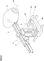
Fig. 4 ] is an exploded perspective view of the transporting conveyor. - [
Fig. 5 ] is a conceptual diagram showing a transporting surface. - [
Fig. 6 ] is a side view of a pressing conveyor. - [
Figs. 7 ] (A) to (C) are explanatory views showing a gyration around a transporting surface width centerline of the transporting conveyor. - [
Fig. 8 ] is an explanatory diagram showing an operation of the bonding devi ce. - [
Fig. 9 ] is a perspective view showing a conventional device for bonding the rubber strip. - Hereinafter, an embodiment of the present invention will be described in detail.
- As shown in
Figs. 1 and2 , a device for bonding a rubber strip 1 of the present embodiment (hereinafter, may be simply called " bonding device 1") comprises anapplicator 4 for transporting an unvulcanized rubber strip T, which is supplied from arubber strip supplier 2, to awound body 3 rotational ly actuated and for applying the rubber strip T around thewound body 3. - In the present embodiment, the
wound body 3 is a former for forming a tire. By winding the rubber strip T around it, rubber members such as a tread rubber, for example, are formed. Thewound body 3 comprises a non-linear cylinder-like profile such as a drum-like profile, for example, in concert with a shape of the tire. For the rubber strip T, a cord can also be buried inside, in this instance, a band layer of the tire is formed. - The
rubber strip supplier 2 supplies the rubber strip T to the bonding device 1. In the present embodiment, therubber strip supplier 2 is a so-called roll stand, which supplies from a wound-up (roll) TR of the rubber strip T previously wound in whorl, winds off the rubber strip T to supply the bonding device 1. The sign J in drawings shows a peeling tape, which is disposed alternately with the rubber strip T so as to prevent from adherence between the rubber strips T on the wound-up TR. The peeling tape J is recovered at the time of winding off of the rubber strip T. - The
rubber strip supplier 2 may be a rubber extrusion device for forming the rubber strip T by extrusion. In this instance, for the extrusion device, a gear pump extrusion device provided on a forward end side with a calender roll may be preferably employed. - The bonding device 1 according to the present embodiment comprises a basal table 5, a lift table 9 supported movably up and down by the basal table 5, and a lateral moving table 6 supported movably in the lateral direction by the lift table 9. To the lateral moving table 6, the
applicator 4 is attached. The lift table 9 is supported movably up and down via a lift means 12. The lift means 12 of the present embodiment comprises a pair ofperpendicular guiding shafts 12a and a perpendicularball screw shaft 12b. In the guidingshaft 12a, an upper end is fixed to the lift table 9, and a lower end is fixed to alower panel 12c. Theball screw shaft 12b is rotatably supported by the lift table 9 and thelower panel 12c, and the lower end portion is connected with a lift motor M1 attached to thelower panel 12c. The basal table 5 comprises asupport panel portion 5a comprising a guide hole for insertion of the guidingshaft 12a and a screw hole screwed together with theball screw shaft 12b. - The lateral moving table 6 according to the present embodiment is movably supported in a X-axis direction parallel to a
shaft center 3i of thewound body 3 via a lateral moving means 13. As shown inFig. 2 , the lateral moving means 13 of the present embodiment comprises aball screw shaft 13b and aguide rail 13a in the X-axis direction disposed in the lift table 9, and an end of theball screw shaft 13b is connected with a lateral move motor (not shown) attached to the lift table 9. The lateral moving table 6 comprises a guide portion guided by theguide rail 13a and a nut portion screwed together with theball screw shaft 13b. Therefore, theapplicator 4 can freely change portions in the up-and-down direction (Z-axis direction) and the lateral direction (X-axis direction) by the actuations of the lift motor M1 and the lateral move motor. - The
applicator 4 comprises at least a transportingconveyor 7 mounted on the lateral moving table 6 integrally movably. The present embodiment shows a case that theapplicator 4 comprises the transportingconveyor 7 and apressing conveyor 8 disposed thereabove. - The transporting
conveyor 7 comprises a plurality of guidingrollers 10 and a transportingbelt 11 guided rotatably by the guidingrollers 10. As shown inFigs. 3 and4 , the transportingbelt 11 is provided in a top surface with a transporting surface 11s, and the rubber strip T is transported on the transportingsurface 11S from a receiving position P1 from therubber strip supplier 2 to a discharging position P2 to thewound body 3. As conceptually shown inFig. 5 , a width center line of the transportingsurface 11S extends in a straight line over the entire length of the transportingsurface 11S. That is to say, the transportingsurface 11S comprises the transportingsurface width centerline 11j extending in a straight line over the entire length thereof. - A plurality of guiding
rollers 10 are distributed into forward-side guiding rollers 10A including a foremost-side guiding roller 10a disposed on the foremost side in the transporting direction, and backward-side guiding rollers 10B including a backmost-side guiding roller 10b disposed on the backmost side in the transporting direction. The forward-side guiding rollers 10A are held tiltibly around the transportingsurface width centerline 11j. Thus, the transportingsurface 11S comprises, as shown inFig. 5 , a twistable twisting transporting surface portion 11SM around the transportingsurface width centerline 11j between a forward-side transporting surface portion 11SA supported by the forward-side guiding rollers 10A and a backward-side transporting surface portion 11SB supported by the backward-side guiding rollers 10B. - In particular, the
applicator 4 comprises afirst frame 15 fixed to the lateral moving table 6 integrally movably, and asecond frame 16 held tiltibly by thefirst frame 15 around the transportingsurface width centerline 11j. - The
first frame 15 comprises a side-panel-likebasal portion 15A rising at one edge of the lateral moving table 6. Thebasal portion 15A extends rearward over a back end of the lateral moving table 6, and thebasal portion 15A is provided on the back end side with a mountingpanel portion 15B for mounting the second frame flatly for example. And to thebasal portion 15A, the backward-side guiding roller 10B is pivoted. - The
second frame 16 comprises asupport shaft 17 being concentric with the transportingsurface width centerline 11j. Thesupport shaft 17 is rotatably pivoted around the transportingsurface width centerline 11j by the bearingholder 18 attached to the mountingpanel portion 15B. Thesecond frame 16 of the present embodiment comprises arear panel portion 16A attached to thesupport shaft 17, and afront panel portion 16B extending toward the forward side replicated from an upper end of therear panel portion 16A, for example. Thefront panel portion 16B is provided on the forward end side with a side-panel-like side panel portion 16B1 parallel to thebasal portion 15A. To the side panel portion 16B1, the forward-side guiding rollers 10A are pivoted. - The
support shaft 17 is connected with an actuation motor (not shown) controllable in angle of rotation such as a step motor. And the backmost-side guiding roller 10b is connected with an actuation motor M2, thereby rotatably actuating the transportingbelt 11. - The
second frame 16 comprises a cutting means 19 for cutting the rubber strip T on the forward-side transporting surface portion 11SA. The cutting means 19 according to the present invention comprises arotary shaft 19A rotatably actuated, and acutter blade 19B extending radially outward from the periphery thereof. In the cutting means 19, thecutter blade 19B goes into a 360-degree roll at the same speed as the rubber strip T, thereby the rubber strip T can be cut while transporting. Thecutter blade 19B is provided on its lower side with a guiding roller 10A1 having a comparatively large diameter, which supports the transportingbelt 11 from underneath at the time of cutting. - The
pressing conveyor 8, as shown inFig. 6 , a plurality ofupper guiding rollers 20 and apressing belt 21 rotatably guided by theupper guiding rollers 20. Thepressing belt 21 pushes the rubber strip T against the transportingbelt 11, thereby preventing peeling, shifting, slipping and the like of the rubber strip T from the transportingbelt 11. A pressing surface 21S of thepressing belt 21 comprises a frontward-side pressing surface portion 21SA pressing the rubber strip T against the forward-side transporting surface portion 11SA, a backward-side pressing surface portion 21SB pressing against the backward-side transporting surface portion 11SB, and a twisting pressing surface portion 21SM pushing against the twisting transporting surface portion 11SM. - In particular, the
upper guiding rollers 20 are distributed into forward-sideupper guide rollers 20A including a foremost-sideupper guide roller 20a disposed on the foremost side in the transporting direction, and backward-sideupper guide rollers 20B including a backmost-sideupper guide roller 20b disposed on the backmost side in the transporting direction. And the backward-sideupper guide rollers 20B are pivoted by thebasal portion 15A of thefi rst frame 15 as the same way as backward-side guiding rollers 10B. The forward-sideupper guide rollers 20A are pivoted by the side panel portion 16B1 of thesecond frame 16 as the same way as the forward-side guiding rollers 10A. - The
pressing belt 21 according to the present embodiment comprises a rearpressing belt 21B disposed on the backward side of the cutting means 19, and a frontpressing belt 21A disposed on the frontward side of the cutting means 19. - The bonding device 1 according to the present embodiment is provided on the frontward side of the transporting
conveyor 7 with a pressure bonding means 22. The pressure bonding means 22 bonds the rubber strip T applied on thewound body 3 by pressing against thewound body 3. The pressure bonding means 22 is provided at a rod lower end of thecylinder 22A with apressure roller 22B pivoted via a holder. Thecylinder 22A is supported by the side panel portion 16B1 of thesecond frame 16, and thepressure roller 22B is pivoted parallel to the forward-side guiding rollers 10A. Therefore, thepressure roller 22B is tiltible around the transportingsurface width centerline 11j and can to bond the rubber strip T with an inclination in concert with the profile of the wound body. - As shown in
Fig. 7 (A) , the transportingbelt 11 of the transportingconveyor 7 has preferably a wider width than the rubber strip T, and thepressing belt 21 of thepressing conveyor 8 is preferably narrower than the rubber strip T. As shown inFigs. 7 (B) and 7 (C) , an gyrating angle theta (θ) gyratable around the transportingsurface width centerline 11j while fastening the rubber strip Twith the narrowpressing belt 21 without changing the lengths of thebelts - In the bonding device 1 according to the present embodiment, as described above, the lift table 9 and the lateral moving table 6 support the
applicator 4 variably in the up-and-down direction (Z-axis direction) and in the lateral direction (X-axis direction). Therefore, the rubber strip T can be accurately bonded in concert with the profile around the non-linear cylinder-like wound body 3 in cooperation with the gyrating motion around the transportingsurface width centerline 11j as shown inFig. 8 . Meanwhile, as substitute for the lift table 9 and the lateral moving table 6, thewound body 3 also can removably support in the up-and-down di rection (Z-axis direction) and in the lateral direction (X-axis direction) with respect to theapplicator 4. - The above has described in detail a particularly preferred embodiment of the present invention, the invention is not limited to the embodiments shown, can be implemented by modifying to various aspects.
-
- 1
- Bonding device
- 3
- wound body
- 4
- Applicator
- 7
- Transporting conveyor
- 8
- Pressing conveyor
- 10
- Guiding roller
- 10a
- Foremost-side guiding roller
- 10A
- Forward-side guiding roller
- 10b
- Backmost-side guiding roller
- 10B
- Backward-side guiding roller
- 11
- Transporting belt
- 11S
- Transporting surface
- 11j
- Transporting surface width centerline
- 11SA
- Forward-side transporting surface portion
- 11SB
- Backward-side transporting surface portion
- 11SM
- Twisting transporting surface portion
- 15
- Fi rst frame
- 16
- Second frame
- 20
- Upper guiding roller
- 21
- Pressing belt
- 21S
- Pressing surface
- 21SA
- Frontward-side pressing surface portion
- 21SB
- Backward-side pressing surface portion
- 21SM
- Twisting pressing surface portion
- T
- Rubber strip
Claims (3)
- A device (1) for bonding a rubber strip comprising an applicator (4) to transport an unvulcanized rubber strip (T) to a non-linear cylinder-like wound body (3) rotationally actuated and to bond the rubber strip (T) around the wound body (3), wherein
the applicator (4) comprises a transporting conveyor (7) having a transporting belt (11) which is rotatably guided by a plurality of guiding rollers (10) and transports the rubber strip (11) on a transporting surface (11S);
the transporting surface (11S) comprises a transporting surface width centerline (11j) extending in a straight line over the entire length of the transporting surface (11S); and
the guiding rollers (10) are distributed into forward-side guiding rollers (10A) including a foremost-side guiding roller (10a) disposed on the foremost side in the transporting direction and backward-side guiding rollers (10B) including a backmost-side guiding roller (10b) disposed on a backmost side in the transporting direction,
characterized in that
the forward-side guiding rollers (10A) are held tiltibly around the transporting surface width centerline (11j), so that the transporting surface (11S) forms a twistable twisting transporting surface portion (11SM) between a forward-side transporting surface portion (11SA) supported by the forward-side guiding rollers (10A) and a backward-side transporting surface portion (11SB) supported by the backward-side guiding rollers (10B). - The device (1) for bonding a rubber strip according to claim 1, wherein the backward-side guiding rollers (10B) are supported by a first frame (15), and the forward-side guiding rollers (10A) are supported by a second frame (16) held tiltibly by the fi rst frame (15) around the transporting surface width centerline (11j).
- The device (1) for bonding a rubber strip according to claim lor 2, wherein the applicator (7) comprises a pressing conveyor (8) having a pressing belt (21) which is rotatably guided by a plurality of upper guiding rollers (20) and presses the rubber strip (T) to the transporting belt (11); and
the pressing belt (21) comprises a pressing surface (21S) comprising
a frontward-side pressing surface portion (21SA) to press the rubber strip (T) against the forward-side transporting surface portion (11SA),
a backward-side pressing surface portion (21SB) to press the rubber strip (T) against the backward-side transporting surface portion (11SB), and
a twisting pressing surface portion (21SM) to press the rubber strip (T) against the twisting transporting surface portion (11SM) .
Applications Claiming Priority (2)
| Application Number | Priority Date | Filing Date | Title |
|---|---|---|---|
| JP2012285675A JP5767623B2 (en) | 2012-12-27 | 2012-12-27 | Rubber strip sticking device |
| PCT/JP2013/082367 WO2014103621A1 (en) | 2012-12-27 | 2013-12-02 | Device for bonding rubber strip |
Publications (3)
| Publication Number | Publication Date |
|---|---|
| EP2939825A1 EP2939825A1 (en) | 2015-11-04 |
| EP2939825A4 EP2939825A4 (en) | 2016-09-21 |
| EP2939825B1 true EP2939825B1 (en) | 2019-02-20 |
Family
ID=51020715
Family Applications (1)
| Application Number | Title | Priority Date | Filing Date |
|---|---|---|---|
| EP13868811.4A Active EP2939825B1 (en) | 2012-12-27 | 2013-12-02 | Device for bonding rubber strip |
Country Status (5)
| Country | Link |
|---|---|
| US (1) | US10421242B2 (en) |
| EP (1) | EP2939825B1 (en) |
| JP (1) | JP5767623B2 (en) |
| CN (1) | CN104918778B (en) |
| WO (1) | WO2014103621A1 (en) |
Cited By (1)
| Publication number | Priority date | Publication date | Assignee | Title |
|---|---|---|---|---|
| EP3760424A1 (en) | 2019-07-04 | 2021-01-06 | Continental Reifen Deutschland GmbH | Method for the production of a pneumatic vehicle tyre, use of strip winding for winding one or more rubber components, device for carrying out the method and a pneumatic vehicle tyre which is produced or can be produced according to the method |
Families Citing this family (6)
| Publication number | Priority date | Publication date | Assignee | Title |
|---|---|---|---|---|
| JP5945290B2 (en) | 2014-02-24 | 2016-07-05 | 住友ゴム工業株式会社 | Tire member forming apparatus |
| JP6417209B2 (en) * | 2014-12-22 | 2018-10-31 | 東洋ゴム工業株式会社 | Groove forming apparatus and groove forming method for belt-shaped rubber member |
| JP6463211B2 (en) * | 2015-04-30 | 2019-01-30 | 住友ゴム工業株式会社 | Pneumatic tire manufacturing method |
| JP7275802B2 (en) * | 2019-04-19 | 2023-05-18 | 住友ゴム工業株式会社 | Applicator for rubber strip |
| CN110341220B (en) * | 2019-07-16 | 2021-02-26 | 山东凯旋橡胶有限公司 | A rubber guide device for tire shoulder pads of a molding machine |
| NL2029062B1 (en) * | 2021-08-26 | 2023-03-15 | Vmi Holland Bv | Strip applicator, strip-winding station and method for applying a strip to a strip-winding drum |
Family Cites Families (21)
| Publication number | Priority date | Publication date | Assignee | Title |
|---|---|---|---|---|
| US3924729A (en) * | 1974-10-08 | 1975-12-09 | Conscale Ab | Belt conveyor weighing system |
| US4330116A (en) * | 1980-10-20 | 1982-05-18 | Newsome John R | Bundling mechanism for signatures |
| JPS60228308A (en) * | 1984-04-25 | 1985-11-13 | Chuo Denki Seisakusho:Kk | Belt conveyor for aligning and conveying parts |
| US4889333A (en) * | 1987-03-09 | 1989-12-26 | Gaemmerler Hagen | Conveying apparatus for paper products, in particular in stream form |
| JP2783804B2 (en) * | 1988-02-10 | 1998-08-06 | 株式会社アマダ | Wire discharge device of wire cut electric discharge machine |
| JPH0818657B2 (en) * | 1988-05-23 | 1996-02-28 | 株式会社三井三池製作所 | Vertical belt conveyor device |
| US5335415A (en) * | 1991-10-30 | 1994-08-09 | Bridgestone Corporation | Apparatus for winding and pressure-fitting a small width strip to a rotating body |
| JP3194765B2 (en) | 1991-11-13 | 2001-08-06 | 株式会社ブリヂストン | Narrow band winding device |
| DE4208653C2 (en) * | 1992-03-18 | 1994-12-01 | Gutehoffnungshuette Man | Continuous bulk material conveyor for optional unloading or loading of ships |
| US7062079B2 (en) * | 2003-02-14 | 2006-06-13 | Ikonisys, Inc. | Method and system for image segmentation |
| JP5129428B2 (en) * | 2003-12-01 | 2013-01-30 | インベンテイオ・アクテイエンゲゼルシヤフト | Elevator system |
| JP2006110856A (en) * | 2004-10-14 | 2006-04-27 | Sumitomo Rubber Ind Ltd | Rubber strip sticking device |
| DE602005004581T2 (en) * | 2004-10-14 | 2009-01-29 | Sumitomo Rubber Industries Ltd., Kobe | Method and device for producing an article by winding a rubber strip on a support body |
| US20060082045A1 (en) * | 2004-10-19 | 2006-04-20 | Eastman Kodak Company | Apparatus and method for stacking media sheets |
| EP1815971B1 (en) * | 2004-10-21 | 2011-04-27 | Bridgestone Corporation | Method and apparatus for applying a band-like rubber member onto a rotational support. |
| DE102005046115A1 (en) * | 2005-09-27 | 2007-03-29 | Continental Aktiengesellschaft | Apparatus for supplying and pressing rubber tapes or strips onto tire layer construction drum, includes frame-mounted rubber profiling device and endless rotating carrier for transporting the shaped material |
| JP4398936B2 (en) | 2005-11-15 | 2010-01-13 | 住友ゴム工業株式会社 | Rubber strip sticking device |
| JP5121835B2 (en) * | 2007-09-05 | 2013-01-16 | 株式会社ブリヂストン | Method and apparatus for producing unvulcanized tire |
| US8691034B2 (en) * | 2008-12-05 | 2014-04-08 | Michelin Recherche Et Technique S.A. | Method and apparatus for forming a tire component upon an axially tapered surface |
| FR2946713B1 (en) * | 2009-06-12 | 2012-03-23 | Skf Aerospace France | MECHANICAL JOINT ASSEMBLY AND METHOD FOR ASSEMBLING SUCH ASSEMBLY. |
| JP4922425B2 (en) * | 2010-03-19 | 2012-04-25 | 住友ゴム工業株式会社 | Rubber strip pressing device |
-
2012
- 2012-12-27 JP JP2012285675A patent/JP5767623B2/en not_active Expired - Fee Related
-
2013
- 2013-12-02 CN CN201380064846.5A patent/CN104918778B/en active Active
- 2013-12-02 EP EP13868811.4A patent/EP2939825B1/en active Active
- 2013-12-02 WO PCT/JP2013/082367 patent/WO2014103621A1/en not_active Ceased
- 2013-12-02 US US14/650,174 patent/US10421242B2/en active Active
Non-Patent Citations (1)
| Title |
|---|
| None * |
Cited By (1)
| Publication number | Priority date | Publication date | Assignee | Title |
|---|---|---|---|---|
| EP3760424A1 (en) | 2019-07-04 | 2021-01-06 | Continental Reifen Deutschland GmbH | Method for the production of a pneumatic vehicle tyre, use of strip winding for winding one or more rubber components, device for carrying out the method and a pneumatic vehicle tyre which is produced or can be produced according to the method |
Also Published As
| Publication number | Publication date |
|---|---|
| CN104918778B (en) | 2017-08-29 |
| EP2939825A1 (en) | 2015-11-04 |
| US10421242B2 (en) | 2019-09-24 |
| JP5767623B2 (en) | 2015-08-19 |
| WO2014103621A1 (en) | 2014-07-03 |
| US20150298412A1 (en) | 2015-10-22 |
| JP2014124929A (en) | 2014-07-07 |
| CN104918778A (en) | 2015-09-16 |
| EP2939825A4 (en) | 2016-09-21 |
Similar Documents
| Publication | Publication Date | Title |
|---|---|---|
| EP2939825B1 (en) | Device for bonding rubber strip | |
| CN1966252A (en) | Device to apply rubber tape | |
| EP3106292B1 (en) | Tire member-forming apparatus | |
| KR102003672B1 (en) | Apparatus and method for attaching object members to the inner surface of a tire | |
| EP1595693B1 (en) | Method and apparatus for producing constituent member of tire | |
| CN216471235U (en) | Winding and discharging device of label paper winding and slitting machine | |
| US20210197500A1 (en) | Apparatus for controllably cutting fibers and related methods | |
| JP6082220B2 (en) | Rubber strip sticking device | |
| KR102081153B1 (en) | Cutting roller and cutting method of sheet using that | |
| CN104999685B (en) | The manufacturing method of pneumatic tire | |
| CN205381783U (en) | High -speed strip machine that divides | |
| KR102797132B1 (en) | Li foil side cladding apparatus and Li foil side cladding method using thereof | |
| JP2009113378A (en) | Cutting and unloading device for tire ply material | |
| KR101415617B1 (en) | Bead winding unit | |
| JP2007030300A (en) | Method and apparatus for producing tire component | |
| US20210178715A1 (en) | Forming device and forming method for green tire | |
| JP2024010735A (en) | strip cutting equipment | |
| JP6693261B2 (en) | Rubber strip recess forming device and rubber strip manufacturing method. | |
| JP2016150468A (en) | Device for production of rubber strip | |
| RU58071U1 (en) | TIRE CUTTING DEVICE | |
| JP2012157975A (en) | Method of forming belt ply | |
| JP2009045698A (en) | Sheet cutter | |
| JP2006123219A (en) | Method and device for peeling strip-like member from liner | |
| JP2006123218A (en) | Feed device of strip-like member | |
| JP2013014407A (en) | Method for manufacturing tape roll |
Legal Events
| Date | Code | Title | Description |
|---|---|---|---|
| PUAI | Public reference made under article 153(3) epc to a published international application that has entered the european phase |
Free format text: ORIGINAL CODE: 0009012 |
|
| 17P | Request for examination filed |
Effective date: 20150706 |
|
| AK | Designated contracting states |
Kind code of ref document: A1 Designated state(s): AL AT BE BG CH CY CZ DE DK EE ES FI FR GB GR HR HU IE IS IT LI LT LU LV MC MK MT NL NO PL PT RO RS SE SI SK SM TR |
|
| AX | Request for extension of the european patent |
Extension state: BA ME |
|
| DAX | Request for extension of the european patent (deleted) | ||
| A4 | Supplementary search report drawn up and despatched |
Effective date: 20160824 |
|
| RIC1 | Information provided on ipc code assigned before grant |
Ipc: B29D 30/16 20060101ALI20160818BHEP Ipc: B29D 30/60 20060101AFI20160818BHEP |
|
| GRAP | Despatch of communication of intention to grant a patent |
Free format text: ORIGINAL CODE: EPIDOSNIGR1 |
|
| STAA | Information on the status of an ep patent application or granted ep patent |
Free format text: STATUS: GRANT OF PATENT IS INTENDED |
|
| INTG | Intention to grant announced |
Effective date: 20180810 |
|
| GRAS | Grant fee paid |
Free format text: ORIGINAL CODE: EPIDOSNIGR3 |
|
| GRAA | (expected) grant |
Free format text: ORIGINAL CODE: 0009210 |
|
| STAA | Information on the status of an ep patent application or granted ep patent |
Free format text: STATUS: THE PATENT HAS BEEN GRANTED |
|
| AK | Designated contracting states |
Kind code of ref document: B1 Designated state(s): AL AT BE BG CH CY CZ DE DK EE ES FI FR GB GR HR HU IE IS IT LI LT LU LV MC MK MT NL NO PL PT RO RS SE SI SK SM TR |
|
| REG | Reference to a national code |
Ref country code: GB Ref legal event code: FG4D |
|
| REG | Reference to a national code |
Ref country code: CH Ref legal event code: EP |
|
| REG | Reference to a national code |
Ref country code: DE Ref legal event code: R096 Ref document number: 602013051222 Country of ref document: DE |
|
| REG | Reference to a national code |
Ref country code: AT Ref legal event code: REF Ref document number: 1097637 Country of ref document: AT Kind code of ref document: T Effective date: 20190315 |
|
| REG | Reference to a national code |
Ref country code: IE Ref legal event code: FG4D |
|
| REG | Reference to a national code |
Ref country code: NL Ref legal event code: MP Effective date: 20190220 |
|
| REG | Reference to a national code |
Ref country code: LT Ref legal event code: MG4D |
|
| PG25 | Lapsed in a contracting state [announced via postgrant information from national office to epo] |
Ref country code: FI Free format text: LAPSE BECAUSE OF FAILURE TO SUBMIT A TRANSLATION OF THE DESCRIPTION OR TO PAY THE FEE WITHIN THE PRESCRIBED TIME-LIMIT Effective date: 20190220 Ref country code: NL Free format text: LAPSE BECAUSE OF FAILURE TO SUBMIT A TRANSLATION OF THE DESCRIPTION OR TO PAY THE FEE WITHIN THE PRESCRIBED TIME-LIMIT Effective date: 20190220 Ref country code: SE Free format text: LAPSE BECAUSE OF FAILURE TO SUBMIT A TRANSLATION OF THE DESCRIPTION OR TO PAY THE FEE WITHIN THE PRESCRIBED TIME-LIMIT Effective date: 20190220 Ref country code: LT Free format text: LAPSE BECAUSE OF FAILURE TO SUBMIT A TRANSLATION OF THE DESCRIPTION OR TO PAY THE FEE WITHIN THE PRESCRIBED TIME-LIMIT Effective date: 20190220 Ref country code: PT Free format text: LAPSE BECAUSE OF FAILURE TO SUBMIT A TRANSLATION OF THE DESCRIPTION OR TO PAY THE FEE WITHIN THE PRESCRIBED TIME-LIMIT Effective date: 20190620 Ref country code: NO Free format text: LAPSE BECAUSE OF FAILURE TO SUBMIT A TRANSLATION OF THE DESCRIPTION OR TO PAY THE FEE WITHIN THE PRESCRIBED TIME-LIMIT Effective date: 20190520 |
|
| PG25 | Lapsed in a contracting state [announced via postgrant information from national office to epo] |
Ref country code: HR Free format text: LAPSE BECAUSE OF FAILURE TO SUBMIT A TRANSLATION OF THE DESCRIPTION OR TO PAY THE FEE WITHIN THE PRESCRIBED TIME-LIMIT Effective date: 20190220 Ref country code: RS Free format text: LAPSE BECAUSE OF FAILURE TO SUBMIT A TRANSLATION OF THE DESCRIPTION OR TO PAY THE FEE WITHIN THE PRESCRIBED TIME-LIMIT Effective date: 20190220 Ref country code: LV Free format text: LAPSE BECAUSE OF FAILURE TO SUBMIT A TRANSLATION OF THE DESCRIPTION OR TO PAY THE FEE WITHIN THE PRESCRIBED TIME-LIMIT Effective date: 20190220 Ref country code: GR Free format text: LAPSE BECAUSE OF FAILURE TO SUBMIT A TRANSLATION OF THE DESCRIPTION OR TO PAY THE FEE WITHIN THE PRESCRIBED TIME-LIMIT Effective date: 20190521 Ref country code: IS Free format text: LAPSE BECAUSE OF FAILURE TO SUBMIT A TRANSLATION OF THE DESCRIPTION OR TO PAY THE FEE WITHIN THE PRESCRIBED TIME-LIMIT Effective date: 20190620 Ref country code: BG Free format text: LAPSE BECAUSE OF FAILURE TO SUBMIT A TRANSLATION OF THE DESCRIPTION OR TO PAY THE FEE WITHIN THE PRESCRIBED TIME-LIMIT Effective date: 20190520 |
|
| REG | Reference to a national code |
Ref country code: AT Ref legal event code: MK05 Ref document number: 1097637 Country of ref document: AT Kind code of ref document: T Effective date: 20190220 |
|
| PG25 | Lapsed in a contracting state [announced via postgrant information from national office to epo] |
Ref country code: EE Free format text: LAPSE BECAUSE OF FAILURE TO SUBMIT A TRANSLATION OF THE DESCRIPTION OR TO PAY THE FEE WITHIN THE PRESCRIBED TIME-LIMIT Effective date: 20190220 Ref country code: RO Free format text: LAPSE BECAUSE OF FAILURE TO SUBMIT A TRANSLATION OF THE DESCRIPTION OR TO PAY THE FEE WITHIN THE PRESCRIBED TIME-LIMIT Effective date: 20190220 Ref country code: ES Free format text: LAPSE BECAUSE OF FAILURE TO SUBMIT A TRANSLATION OF THE DESCRIPTION OR TO PAY THE FEE WITHIN THE PRESCRIBED TIME-LIMIT Effective date: 20190220 Ref country code: CZ Free format text: LAPSE BECAUSE OF FAILURE TO SUBMIT A TRANSLATION OF THE DESCRIPTION OR TO PAY THE FEE WITHIN THE PRESCRIBED TIME-LIMIT Effective date: 20190220 Ref country code: AL Free format text: LAPSE BECAUSE OF FAILURE TO SUBMIT A TRANSLATION OF THE DESCRIPTION OR TO PAY THE FEE WITHIN THE PRESCRIBED TIME-LIMIT Effective date: 20190220 Ref country code: IT Free format text: LAPSE BECAUSE OF FAILURE TO SUBMIT A TRANSLATION OF THE DESCRIPTION OR TO PAY THE FEE WITHIN THE PRESCRIBED TIME-LIMIT Effective date: 20190220 Ref country code: DK Free format text: LAPSE BECAUSE OF FAILURE TO SUBMIT A TRANSLATION OF THE DESCRIPTION OR TO PAY THE FEE WITHIN THE PRESCRIBED TIME-LIMIT Effective date: 20190220 Ref country code: SK Free format text: LAPSE BECAUSE OF FAILURE TO SUBMIT A TRANSLATION OF THE DESCRIPTION OR TO PAY THE FEE WITHIN THE PRESCRIBED TIME-LIMIT Effective date: 20190220 |
|
| REG | Reference to a national code |
Ref country code: DE Ref legal event code: R097 Ref document number: 602013051222 Country of ref document: DE |
|
| PG25 | Lapsed in a contracting state [announced via postgrant information from national office to epo] |
Ref country code: PL Free format text: LAPSE BECAUSE OF FAILURE TO SUBMIT A TRANSLATION OF THE DESCRIPTION OR TO PAY THE FEE WITHIN THE PRESCRIBED TIME-LIMIT Effective date: 20190220 Ref country code: SM Free format text: LAPSE BECAUSE OF FAILURE TO SUBMIT A TRANSLATION OF THE DESCRIPTION OR TO PAY THE FEE WITHIN THE PRESCRIBED TIME-LIMIT Effective date: 20190220 |
|
| PLBE | No opposition filed within time limit |
Free format text: ORIGINAL CODE: 0009261 |
|
| STAA | Information on the status of an ep patent application or granted ep patent |
Free format text: STATUS: NO OPPOSITION FILED WITHIN TIME LIMIT |
|
| PG25 | Lapsed in a contracting state [announced via postgrant information from national office to epo] |
Ref country code: AT Free format text: LAPSE BECAUSE OF FAILURE TO SUBMIT A TRANSLATION OF THE DESCRIPTION OR TO PAY THE FEE WITHIN THE PRESCRIBED TIME-LIMIT Effective date: 20190220 |
|
| 26N | No opposition filed |
Effective date: 20191121 |
|
| PG25 | Lapsed in a contracting state [announced via postgrant information from national office to epo] |
Ref country code: SI Free format text: LAPSE BECAUSE OF FAILURE TO SUBMIT A TRANSLATION OF THE DESCRIPTION OR TO PAY THE FEE WITHIN THE PRESCRIBED TIME-LIMIT Effective date: 20190220 |
|
| PG25 | Lapsed in a contracting state [announced via postgrant information from national office to epo] |
Ref country code: TR Free format text: LAPSE BECAUSE OF FAILURE TO SUBMIT A TRANSLATION OF THE DESCRIPTION OR TO PAY THE FEE WITHIN THE PRESCRIBED TIME-LIMIT Effective date: 20190220 |
|
| REG | Reference to a national code |
Ref country code: CH Ref legal event code: PL |
|
| REG | Reference to a national code |
Ref country code: BE Ref legal event code: MM Effective date: 20191231 |
|
| PG25 | Lapsed in a contracting state [announced via postgrant information from national office to epo] |
Ref country code: MC Free format text: LAPSE BECAUSE OF FAILURE TO SUBMIT A TRANSLATION OF THE DESCRIPTION OR TO PAY THE FEE WITHIN THE PRESCRIBED TIME-LIMIT Effective date: 20190220 |
|
| GBPC | Gb: european patent ceased through non-payment of renewal fee |
Effective date: 20191202 |
|
| PG25 | Lapsed in a contracting state [announced via postgrant information from national office to epo] |
Ref country code: GB Free format text: LAPSE BECAUSE OF NON-PAYMENT OF DUE FEES Effective date: 20191202 Ref country code: IE Free format text: LAPSE BECAUSE OF NON-PAYMENT OF DUE FEES Effective date: 20191202 Ref country code: LU Free format text: LAPSE BECAUSE OF NON-PAYMENT OF DUE FEES Effective date: 20191202 |
|
| PG25 | Lapsed in a contracting state [announced via postgrant information from national office to epo] |
Ref country code: LI Free format text: LAPSE BECAUSE OF NON-PAYMENT OF DUE FEES Effective date: 20191231 Ref country code: BE Free format text: LAPSE BECAUSE OF NON-PAYMENT OF DUE FEES Effective date: 20191231 Ref country code: CH Free format text: LAPSE BECAUSE OF NON-PAYMENT OF DUE FEES Effective date: 20191231 |
|
| PG25 | Lapsed in a contracting state [announced via postgrant information from national office to epo] |
Ref country code: CY Free format text: LAPSE BECAUSE OF FAILURE TO SUBMIT A TRANSLATION OF THE DESCRIPTION OR TO PAY THE FEE WITHIN THE PRESCRIBED TIME-LIMIT Effective date: 20190220 |
|
| PG25 | Lapsed in a contracting state [announced via postgrant information from national office to epo] |
Ref country code: HU Free format text: LAPSE BECAUSE OF FAILURE TO SUBMIT A TRANSLATION OF THE DESCRIPTION OR TO PAY THE FEE WITHIN THE PRESCRIBED TIME-LIMIT; INVALID AB INITIO Effective date: 20131202 Ref country code: MT Free format text: LAPSE BECAUSE OF FAILURE TO SUBMIT A TRANSLATION OF THE DESCRIPTION OR TO PAY THE FEE WITHIN THE PRESCRIBED TIME-LIMIT Effective date: 20190220 |
|
| PG25 | Lapsed in a contracting state [announced via postgrant information from national office to epo] |
Ref country code: MK Free format text: LAPSE BECAUSE OF FAILURE TO SUBMIT A TRANSLATION OF THE DESCRIPTION OR TO PAY THE FEE WITHIN THE PRESCRIBED TIME-LIMIT Effective date: 20190220 |
|
| P01 | Opt-out of the competence of the unified patent court (upc) registered |
Effective date: 20230510 |
|
| PGFP | Annual fee paid to national office [announced via postgrant information from national office to epo] |
Ref country code: DE Payment date: 20241029 Year of fee payment: 12 |
|
| PGFP | Annual fee paid to national office [announced via postgrant information from national office to epo] |
Ref country code: FR Payment date: 20241111 Year of fee payment: 12 |