EP2939639A1 - Implant rachidien auto-pivotant et instrumentations associées - Google Patents
Implant rachidien auto-pivotant et instrumentations associées Download PDFInfo
- Publication number
- EP2939639A1 EP2939639A1 EP15170437.6A EP15170437A EP2939639A1 EP 2939639 A1 EP2939639 A1 EP 2939639A1 EP 15170437 A EP15170437 A EP 15170437A EP 2939639 A1 EP2939639 A1 EP 2939639A1
- Authority
- EP
- European Patent Office
- Prior art keywords
- post
- instrument
- anterior
- implant
- outer member
- Prior art date
- Legal status (The legal status is an assumption and is not a legal conclusion. Google has not performed a legal analysis and makes no representation as to the accuracy of the status listed.)
- Granted
Links
- 239000007943 implant Substances 0.000 title claims abstract description 201
- 238000003780 insertion Methods 0.000 claims abstract description 111
- 230000037431 insertion Effects 0.000 claims abstract description 111
- 230000007246 mechanism Effects 0.000 claims description 7
- 230000008878 coupling Effects 0.000 claims description 4
- 238000010168 coupling process Methods 0.000 claims description 4
- 238000005859 coupling reaction Methods 0.000 claims description 4
- 230000007704 transition Effects 0.000 claims 1
- 238000000034 method Methods 0.000 description 19
- 125000006850 spacer group Chemical group 0.000 description 9
- 239000000463 material Substances 0.000 description 8
- 210000000988 bone and bone Anatomy 0.000 description 6
- 238000013459 approach Methods 0.000 description 5
- 230000004927 fusion Effects 0.000 description 5
- 230000003993 interaction Effects 0.000 description 5
- 230000013011 mating Effects 0.000 description 5
- 230000002708 enhancing effect Effects 0.000 description 4
- 238000003384 imaging method Methods 0.000 description 4
- 239000003550 marker Substances 0.000 description 4
- RTAQQCXQSZGOHL-UHFFFAOYSA-N Titanium Chemical compound [Ti] RTAQQCXQSZGOHL-UHFFFAOYSA-N 0.000 description 3
- 230000008569 process Effects 0.000 description 3
- 229910001220 stainless steel Inorganic materials 0.000 description 3
- 239000010935 stainless steel Substances 0.000 description 3
- 238000001356 surgical procedure Methods 0.000 description 3
- 239000010936 titanium Substances 0.000 description 3
- 229910052719 titanium Inorganic materials 0.000 description 3
- 241000234295 Musa Species 0.000 description 2
- 235000018290 Musa x paradisiaca Nutrition 0.000 description 2
- 244000046052 Phaseolus vulgaris Species 0.000 description 2
- 230000015572 biosynthetic process Effects 0.000 description 2
- 238000012966 insertion method Methods 0.000 description 2
- 229920001652 poly(etherketoneketone) Polymers 0.000 description 2
- 238000012800 visualization Methods 0.000 description 2
- 241000196324 Embryophyta Species 0.000 description 1
- 230000009471 action Effects 0.000 description 1
- 239000011324 bead Substances 0.000 description 1
- 239000000560 biocompatible material Substances 0.000 description 1
- 230000008468 bone growth Effects 0.000 description 1
- 230000006835 compression Effects 0.000 description 1
- 238000007906 compression Methods 0.000 description 1
- 238000002594 fluoroscopy Methods 0.000 description 1
- 230000008676 import Effects 0.000 description 1
- 238000012986 modification Methods 0.000 description 1
- 230000004048 modification Effects 0.000 description 1
- 229920000642 polymer Polymers 0.000 description 1
- 230000001737 promoting effect Effects 0.000 description 1
- 230000008439 repair process Effects 0.000 description 1
- 229910052715 tantalum Inorganic materials 0.000 description 1
- GUVRBAGPIYLISA-UHFFFAOYSA-N tantalum atom Chemical compound [Ta] GUVRBAGPIYLISA-UHFFFAOYSA-N 0.000 description 1
- -1 titanium-aluminum-niobium Chemical compound 0.000 description 1
Images


Classifications
-
- A—HUMAN NECESSITIES
- A61—MEDICAL OR VETERINARY SCIENCE; HYGIENE
- A61F—FILTERS IMPLANTABLE INTO BLOOD VESSELS; PROSTHESES; DEVICES PROVIDING PATENCY TO, OR PREVENTING COLLAPSING OF, TUBULAR STRUCTURES OF THE BODY, e.g. STENTS; ORTHOPAEDIC, NURSING OR CONTRACEPTIVE DEVICES; FOMENTATION; TREATMENT OR PROTECTION OF EYES OR EARS; BANDAGES, DRESSINGS OR ABSORBENT PADS; FIRST-AID KITS
- A61F2/00—Filters implantable into blood vessels; Prostheses, i.e. artificial substitutes or replacements for parts of the body; Appliances for connecting them with the body; Devices providing patency to, or preventing collapsing of, tubular structures of the body, e.g. stents
- A61F2/02—Prostheses implantable into the body
- A61F2/30—Joints
- A61F2/46—Special tools or methods for implanting or extracting artificial joints, accessories, bone grafts or substitutes, or particular adaptations therefor
- A61F2/4603—Special tools or methods for implanting or extracting artificial joints, accessories, bone grafts or substitutes, or particular adaptations therefor for insertion or extraction of endoprosthetic joints or of accessories thereof
- A61F2/4611—Special tools or methods for implanting or extracting artificial joints, accessories, bone grafts or substitutes, or particular adaptations therefor for insertion or extraction of endoprosthetic joints or of accessories thereof of spinal prostheses
-
- A—HUMAN NECESSITIES
- A61—MEDICAL OR VETERINARY SCIENCE; HYGIENE
- A61F—FILTERS IMPLANTABLE INTO BLOOD VESSELS; PROSTHESES; DEVICES PROVIDING PATENCY TO, OR PREVENTING COLLAPSING OF, TUBULAR STRUCTURES OF THE BODY, e.g. STENTS; ORTHOPAEDIC, NURSING OR CONTRACEPTIVE DEVICES; FOMENTATION; TREATMENT OR PROTECTION OF EYES OR EARS; BANDAGES, DRESSINGS OR ABSORBENT PADS; FIRST-AID KITS
- A61F2/00—Filters implantable into blood vessels; Prostheses, i.e. artificial substitutes or replacements for parts of the body; Appliances for connecting them with the body; Devices providing patency to, or preventing collapsing of, tubular structures of the body, e.g. stents
- A61F2/02—Prostheses implantable into the body
- A61F2/30—Joints
- A61F2/44—Joints for the spine, e.g. vertebrae, spinal discs
- A61F2/4455—Joints for the spine, e.g. vertebrae, spinal discs for the fusion of spinal bodies, e.g. intervertebral fusion of adjacent spinal bodies, e.g. fusion cages
- A61F2/4465—Joints for the spine, e.g. vertebrae, spinal discs for the fusion of spinal bodies, e.g. intervertebral fusion of adjacent spinal bodies, e.g. fusion cages having a circular or kidney shaped cross-section substantially perpendicular to the axis of the spine
-
- A—HUMAN NECESSITIES
- A61—MEDICAL OR VETERINARY SCIENCE; HYGIENE
- A61F—FILTERS IMPLANTABLE INTO BLOOD VESSELS; PROSTHESES; DEVICES PROVIDING PATENCY TO, OR PREVENTING COLLAPSING OF, TUBULAR STRUCTURES OF THE BODY, e.g. STENTS; ORTHOPAEDIC, NURSING OR CONTRACEPTIVE DEVICES; FOMENTATION; TREATMENT OR PROTECTION OF EYES OR EARS; BANDAGES, DRESSINGS OR ABSORBENT PADS; FIRST-AID KITS
- A61F2/00—Filters implantable into blood vessels; Prostheses, i.e. artificial substitutes or replacements for parts of the body; Appliances for connecting them with the body; Devices providing patency to, or preventing collapsing of, tubular structures of the body, e.g. stents
- A61F2/02—Prostheses implantable into the body
- A61F2/30—Joints
- A61F2/46—Special tools or methods for implanting or extracting artificial joints, accessories, bone grafts or substitutes, or particular adaptations therefor
- A61F2/4684—Trial or dummy prostheses
-
- A—HUMAN NECESSITIES
- A61—MEDICAL OR VETERINARY SCIENCE; HYGIENE
- A61F—FILTERS IMPLANTABLE INTO BLOOD VESSELS; PROSTHESES; DEVICES PROVIDING PATENCY TO, OR PREVENTING COLLAPSING OF, TUBULAR STRUCTURES OF THE BODY, e.g. STENTS; ORTHOPAEDIC, NURSING OR CONTRACEPTIVE DEVICES; FOMENTATION; TREATMENT OR PROTECTION OF EYES OR EARS; BANDAGES, DRESSINGS OR ABSORBENT PADS; FIRST-AID KITS
- A61F2/00—Filters implantable into blood vessels; Prostheses, i.e. artificial substitutes or replacements for parts of the body; Appliances for connecting them with the body; Devices providing patency to, or preventing collapsing of, tubular structures of the body, e.g. stents
- A61F2/02—Prostheses implantable into the body
- A61F2/28—Bones
- A61F2002/2835—Bone graft implants for filling a bony defect or an endoprosthesis cavity, e.g. by synthetic material or biological material
-
- A—HUMAN NECESSITIES
- A61—MEDICAL OR VETERINARY SCIENCE; HYGIENE
- A61F—FILTERS IMPLANTABLE INTO BLOOD VESSELS; PROSTHESES; DEVICES PROVIDING PATENCY TO, OR PREVENTING COLLAPSING OF, TUBULAR STRUCTURES OF THE BODY, e.g. STENTS; ORTHOPAEDIC, NURSING OR CONTRACEPTIVE DEVICES; FOMENTATION; TREATMENT OR PROTECTION OF EYES OR EARS; BANDAGES, DRESSINGS OR ABSORBENT PADS; FIRST-AID KITS
- A61F2/00—Filters implantable into blood vessels; Prostheses, i.e. artificial substitutes or replacements for parts of the body; Appliances for connecting them with the body; Devices providing patency to, or preventing collapsing of, tubular structures of the body, e.g. stents
- A61F2/02—Prostheses implantable into the body
- A61F2/30—Joints
- A61F2002/30001—Additional features of subject-matter classified in A61F2/28, A61F2/30 and subgroups thereof
- A61F2002/30003—Material related properties of the prosthesis or of a coating on the prosthesis
- A61F2002/3006—Properties of materials and coating materials
- A61F2002/3008—Properties of materials and coating materials radio-opaque, e.g. radio-opaque markers
-
- A—HUMAN NECESSITIES
- A61—MEDICAL OR VETERINARY SCIENCE; HYGIENE
- A61F—FILTERS IMPLANTABLE INTO BLOOD VESSELS; PROSTHESES; DEVICES PROVIDING PATENCY TO, OR PREVENTING COLLAPSING OF, TUBULAR STRUCTURES OF THE BODY, e.g. STENTS; ORTHOPAEDIC, NURSING OR CONTRACEPTIVE DEVICES; FOMENTATION; TREATMENT OR PROTECTION OF EYES OR EARS; BANDAGES, DRESSINGS OR ABSORBENT PADS; FIRST-AID KITS
- A61F2/00—Filters implantable into blood vessels; Prostheses, i.e. artificial substitutes or replacements for parts of the body; Appliances for connecting them with the body; Devices providing patency to, or preventing collapsing of, tubular structures of the body, e.g. stents
- A61F2/02—Prostheses implantable into the body
- A61F2/30—Joints
- A61F2002/30001—Additional features of subject-matter classified in A61F2/28, A61F2/30 and subgroups thereof
- A61F2002/30108—Shapes
- A61F2002/3011—Cross-sections or two-dimensional shapes
- A61F2002/30112—Rounded shapes, e.g. with rounded corners
- A61F2002/30125—Rounded shapes, e.g. with rounded corners elliptical or oval
-
- A—HUMAN NECESSITIES
- A61—MEDICAL OR VETERINARY SCIENCE; HYGIENE
- A61F—FILTERS IMPLANTABLE INTO BLOOD VESSELS; PROSTHESES; DEVICES PROVIDING PATENCY TO, OR PREVENTING COLLAPSING OF, TUBULAR STRUCTURES OF THE BODY, e.g. STENTS; ORTHOPAEDIC, NURSING OR CONTRACEPTIVE DEVICES; FOMENTATION; TREATMENT OR PROTECTION OF EYES OR EARS; BANDAGES, DRESSINGS OR ABSORBENT PADS; FIRST-AID KITS
- A61F2/00—Filters implantable into blood vessels; Prostheses, i.e. artificial substitutes or replacements for parts of the body; Appliances for connecting them with the body; Devices providing patency to, or preventing collapsing of, tubular structures of the body, e.g. stents
- A61F2/02—Prostheses implantable into the body
- A61F2/30—Joints
- A61F2002/30001—Additional features of subject-matter classified in A61F2/28, A61F2/30 and subgroups thereof
- A61F2002/30108—Shapes
- A61F2002/3011—Cross-sections or two-dimensional shapes
- A61F2002/30112—Rounded shapes, e.g. with rounded corners
- A61F2002/30133—Rounded shapes, e.g. with rounded corners kidney-shaped or bean-shaped
-
- A—HUMAN NECESSITIES
- A61—MEDICAL OR VETERINARY SCIENCE; HYGIENE
- A61F—FILTERS IMPLANTABLE INTO BLOOD VESSELS; PROSTHESES; DEVICES PROVIDING PATENCY TO, OR PREVENTING COLLAPSING OF, TUBULAR STRUCTURES OF THE BODY, e.g. STENTS; ORTHOPAEDIC, NURSING OR CONTRACEPTIVE DEVICES; FOMENTATION; TREATMENT OR PROTECTION OF EYES OR EARS; BANDAGES, DRESSINGS OR ABSORBENT PADS; FIRST-AID KITS
- A61F2/00—Filters implantable into blood vessels; Prostheses, i.e. artificial substitutes or replacements for parts of the body; Appliances for connecting them with the body; Devices providing patency to, or preventing collapsing of, tubular structures of the body, e.g. stents
- A61F2/02—Prostheses implantable into the body
- A61F2/30—Joints
- A61F2002/30001—Additional features of subject-matter classified in A61F2/28, A61F2/30 and subgroups thereof
- A61F2002/30316—The prosthesis having different structural features at different locations within the same prosthesis; Connections between prosthetic parts; Special structural features of bone or joint prostheses not otherwise provided for
- A61F2002/30329—Connections or couplings between prosthetic parts, e.g. between modular parts; Connecting elements
- A61F2002/30383—Connections or couplings between prosthetic parts, e.g. between modular parts; Connecting elements made by laterally inserting a protrusion, e.g. a rib into a complementarily-shaped groove
-
- A—HUMAN NECESSITIES
- A61—MEDICAL OR VETERINARY SCIENCE; HYGIENE
- A61F—FILTERS IMPLANTABLE INTO BLOOD VESSELS; PROSTHESES; DEVICES PROVIDING PATENCY TO, OR PREVENTING COLLAPSING OF, TUBULAR STRUCTURES OF THE BODY, e.g. STENTS; ORTHOPAEDIC, NURSING OR CONTRACEPTIVE DEVICES; FOMENTATION; TREATMENT OR PROTECTION OF EYES OR EARS; BANDAGES, DRESSINGS OR ABSORBENT PADS; FIRST-AID KITS
- A61F2/00—Filters implantable into blood vessels; Prostheses, i.e. artificial substitutes or replacements for parts of the body; Appliances for connecting them with the body; Devices providing patency to, or preventing collapsing of, tubular structures of the body, e.g. stents
- A61F2/02—Prostheses implantable into the body
- A61F2/30—Joints
- A61F2002/30001—Additional features of subject-matter classified in A61F2/28, A61F2/30 and subgroups thereof
- A61F2002/30316—The prosthesis having different structural features at different locations within the same prosthesis; Connections between prosthetic parts; Special structural features of bone or joint prostheses not otherwise provided for
- A61F2002/30329—Connections or couplings between prosthetic parts, e.g. between modular parts; Connecting elements
- A61F2002/30471—Connections or couplings between prosthetic parts, e.g. between modular parts; Connecting elements connected by a hinged linkage mechanism, e.g. of the single-bar or multi-bar linkage type
-
- A—HUMAN NECESSITIES
- A61—MEDICAL OR VETERINARY SCIENCE; HYGIENE
- A61F—FILTERS IMPLANTABLE INTO BLOOD VESSELS; PROSTHESES; DEVICES PROVIDING PATENCY TO, OR PREVENTING COLLAPSING OF, TUBULAR STRUCTURES OF THE BODY, e.g. STENTS; ORTHOPAEDIC, NURSING OR CONTRACEPTIVE DEVICES; FOMENTATION; TREATMENT OR PROTECTION OF EYES OR EARS; BANDAGES, DRESSINGS OR ABSORBENT PADS; FIRST-AID KITS
- A61F2/00—Filters implantable into blood vessels; Prostheses, i.e. artificial substitutes or replacements for parts of the body; Appliances for connecting them with the body; Devices providing patency to, or preventing collapsing of, tubular structures of the body, e.g. stents
- A61F2/02—Prostheses implantable into the body
- A61F2/30—Joints
- A61F2002/30001—Additional features of subject-matter classified in A61F2/28, A61F2/30 and subgroups thereof
- A61F2002/30316—The prosthesis having different structural features at different locations within the same prosthesis; Connections between prosthetic parts; Special structural features of bone or joint prostheses not otherwise provided for
- A61F2002/30535—Special structural features of bone or joint prostheses not otherwise provided for
- A61F2002/30537—Special structural features of bone or joint prostheses not otherwise provided for adjustable
- A61F2002/30538—Special structural features of bone or joint prostheses not otherwise provided for adjustable for adjusting angular orientation
-
- A—HUMAN NECESSITIES
- A61—MEDICAL OR VETERINARY SCIENCE; HYGIENE
- A61F—FILTERS IMPLANTABLE INTO BLOOD VESSELS; PROSTHESES; DEVICES PROVIDING PATENCY TO, OR PREVENTING COLLAPSING OF, TUBULAR STRUCTURES OF THE BODY, e.g. STENTS; ORTHOPAEDIC, NURSING OR CONTRACEPTIVE DEVICES; FOMENTATION; TREATMENT OR PROTECTION OF EYES OR EARS; BANDAGES, DRESSINGS OR ABSORBENT PADS; FIRST-AID KITS
- A61F2/00—Filters implantable into blood vessels; Prostheses, i.e. artificial substitutes or replacements for parts of the body; Appliances for connecting them with the body; Devices providing patency to, or preventing collapsing of, tubular structures of the body, e.g. stents
- A61F2/02—Prostheses implantable into the body
- A61F2/30—Joints
- A61F2002/30001—Additional features of subject-matter classified in A61F2/28, A61F2/30 and subgroups thereof
- A61F2002/30316—The prosthesis having different structural features at different locations within the same prosthesis; Connections between prosthetic parts; Special structural features of bone or joint prostheses not otherwise provided for
- A61F2002/30535—Special structural features of bone or joint prostheses not otherwise provided for
- A61F2002/30593—Special structural features of bone or joint prostheses not otherwise provided for hollow
-
- A—HUMAN NECESSITIES
- A61—MEDICAL OR VETERINARY SCIENCE; HYGIENE
- A61F—FILTERS IMPLANTABLE INTO BLOOD VESSELS; PROSTHESES; DEVICES PROVIDING PATENCY TO, OR PREVENTING COLLAPSING OF, TUBULAR STRUCTURES OF THE BODY, e.g. STENTS; ORTHOPAEDIC, NURSING OR CONTRACEPTIVE DEVICES; FOMENTATION; TREATMENT OR PROTECTION OF EYES OR EARS; BANDAGES, DRESSINGS OR ABSORBENT PADS; FIRST-AID KITS
- A61F2/00—Filters implantable into blood vessels; Prostheses, i.e. artificial substitutes or replacements for parts of the body; Appliances for connecting them with the body; Devices providing patency to, or preventing collapsing of, tubular structures of the body, e.g. stents
- A61F2/02—Prostheses implantable into the body
- A61F2/30—Joints
- A61F2002/30001—Additional features of subject-matter classified in A61F2/28, A61F2/30 and subgroups thereof
- A61F2002/30316—The prosthesis having different structural features at different locations within the same prosthesis; Connections between prosthetic parts; Special structural features of bone or joint prostheses not otherwise provided for
- A61F2002/30535—Special structural features of bone or joint prostheses not otherwise provided for
- A61F2002/30594—Special structural features of bone or joint prostheses not otherwise provided for slotted, e.g. radial or meridian slot ending in a polar aperture, non-polar slots, horizontal or arcuate slots
-
- A—HUMAN NECESSITIES
- A61—MEDICAL OR VETERINARY SCIENCE; HYGIENE
- A61F—FILTERS IMPLANTABLE INTO BLOOD VESSELS; PROSTHESES; DEVICES PROVIDING PATENCY TO, OR PREVENTING COLLAPSING OF, TUBULAR STRUCTURES OF THE BODY, e.g. STENTS; ORTHOPAEDIC, NURSING OR CONTRACEPTIVE DEVICES; FOMENTATION; TREATMENT OR PROTECTION OF EYES OR EARS; BANDAGES, DRESSINGS OR ABSORBENT PADS; FIRST-AID KITS
- A61F2/00—Filters implantable into blood vessels; Prostheses, i.e. artificial substitutes or replacements for parts of the body; Appliances for connecting them with the body; Devices providing patency to, or preventing collapsing of, tubular structures of the body, e.g. stents
- A61F2/02—Prostheses implantable into the body
- A61F2/30—Joints
- A61F2002/30001—Additional features of subject-matter classified in A61F2/28, A61F2/30 and subgroups thereof
- A61F2002/30316—The prosthesis having different structural features at different locations within the same prosthesis; Connections between prosthetic parts; Special structural features of bone or joint prostheses not otherwise provided for
- A61F2002/30535—Special structural features of bone or joint prostheses not otherwise provided for
- A61F2002/30604—Special structural features of bone or joint prostheses not otherwise provided for modular
- A61F2002/30616—Sets comprising a plurality of prosthetic parts of different sizes or orientations
-
- A—HUMAN NECESSITIES
- A61—MEDICAL OR VETERINARY SCIENCE; HYGIENE
- A61F—FILTERS IMPLANTABLE INTO BLOOD VESSELS; PROSTHESES; DEVICES PROVIDING PATENCY TO, OR PREVENTING COLLAPSING OF, TUBULAR STRUCTURES OF THE BODY, e.g. STENTS; ORTHOPAEDIC, NURSING OR CONTRACEPTIVE DEVICES; FOMENTATION; TREATMENT OR PROTECTION OF EYES OR EARS; BANDAGES, DRESSINGS OR ABSORBENT PADS; FIRST-AID KITS
- A61F2/00—Filters implantable into blood vessels; Prostheses, i.e. artificial substitutes or replacements for parts of the body; Appliances for connecting them with the body; Devices providing patency to, or preventing collapsing of, tubular structures of the body, e.g. stents
- A61F2/02—Prostheses implantable into the body
- A61F2/30—Joints
- A61F2/30767—Special external or bone-contacting surface, e.g. coating for improving bone ingrowth
- A61F2/30771—Special external or bone-contacting surface, e.g. coating for improving bone ingrowth applied in original prostheses, e.g. holes or grooves
- A61F2002/30772—Apertures or holes, e.g. of circular cross section
-
- A—HUMAN NECESSITIES
- A61—MEDICAL OR VETERINARY SCIENCE; HYGIENE
- A61F—FILTERS IMPLANTABLE INTO BLOOD VESSELS; PROSTHESES; DEVICES PROVIDING PATENCY TO, OR PREVENTING COLLAPSING OF, TUBULAR STRUCTURES OF THE BODY, e.g. STENTS; ORTHOPAEDIC, NURSING OR CONTRACEPTIVE DEVICES; FOMENTATION; TREATMENT OR PROTECTION OF EYES OR EARS; BANDAGES, DRESSINGS OR ABSORBENT PADS; FIRST-AID KITS
- A61F2/00—Filters implantable into blood vessels; Prostheses, i.e. artificial substitutes or replacements for parts of the body; Appliances for connecting them with the body; Devices providing patency to, or preventing collapsing of, tubular structures of the body, e.g. stents
- A61F2/02—Prostheses implantable into the body
- A61F2/30—Joints
- A61F2/30767—Special external or bone-contacting surface, e.g. coating for improving bone ingrowth
- A61F2/30771—Special external or bone-contacting surface, e.g. coating for improving bone ingrowth applied in original prostheses, e.g. holes or grooves
- A61F2002/3082—Grooves
-
- A—HUMAN NECESSITIES
- A61—MEDICAL OR VETERINARY SCIENCE; HYGIENE
- A61F—FILTERS IMPLANTABLE INTO BLOOD VESSELS; PROSTHESES; DEVICES PROVIDING PATENCY TO, OR PREVENTING COLLAPSING OF, TUBULAR STRUCTURES OF THE BODY, e.g. STENTS; ORTHOPAEDIC, NURSING OR CONTRACEPTIVE DEVICES; FOMENTATION; TREATMENT OR PROTECTION OF EYES OR EARS; BANDAGES, DRESSINGS OR ABSORBENT PADS; FIRST-AID KITS
- A61F2/00—Filters implantable into blood vessels; Prostheses, i.e. artificial substitutes or replacements for parts of the body; Appliances for connecting them with the body; Devices providing patency to, or preventing collapsing of, tubular structures of the body, e.g. stents
- A61F2/02—Prostheses implantable into the body
- A61F2/30—Joints
- A61F2/30767—Special external or bone-contacting surface, e.g. coating for improving bone ingrowth
- A61F2/30771—Special external or bone-contacting surface, e.g. coating for improving bone ingrowth applied in original prostheses, e.g. holes or grooves
- A61F2002/30841—Sharp anchoring protrusions for impaction into the bone, e.g. sharp pins, spikes
- A61F2002/30843—Pyramidally-shaped
-
- A—HUMAN NECESSITIES
- A61—MEDICAL OR VETERINARY SCIENCE; HYGIENE
- A61F—FILTERS IMPLANTABLE INTO BLOOD VESSELS; PROSTHESES; DEVICES PROVIDING PATENCY TO, OR PREVENTING COLLAPSING OF, TUBULAR STRUCTURES OF THE BODY, e.g. STENTS; ORTHOPAEDIC, NURSING OR CONTRACEPTIVE DEVICES; FOMENTATION; TREATMENT OR PROTECTION OF EYES OR EARS; BANDAGES, DRESSINGS OR ABSORBENT PADS; FIRST-AID KITS
- A61F2/00—Filters implantable into blood vessels; Prostheses, i.e. artificial substitutes or replacements for parts of the body; Appliances for connecting them with the body; Devices providing patency to, or preventing collapsing of, tubular structures of the body, e.g. stents
- A61F2/02—Prostheses implantable into the body
- A61F2/30—Joints
- A61F2/30767—Special external or bone-contacting surface, e.g. coating for improving bone ingrowth
- A61F2/30771—Special external or bone-contacting surface, e.g. coating for improving bone ingrowth applied in original prostheses, e.g. holes or grooves
- A61F2002/30878—Special external or bone-contacting surface, e.g. coating for improving bone ingrowth applied in original prostheses, e.g. holes or grooves with non-sharp protrusions, for instance contacting the bone for anchoring, e.g. keels, pegs, pins, posts, shanks, stems, struts
- A61F2002/30879—Ribs
-
- A—HUMAN NECESSITIES
- A61—MEDICAL OR VETERINARY SCIENCE; HYGIENE
- A61F—FILTERS IMPLANTABLE INTO BLOOD VESSELS; PROSTHESES; DEVICES PROVIDING PATENCY TO, OR PREVENTING COLLAPSING OF, TUBULAR STRUCTURES OF THE BODY, e.g. STENTS; ORTHOPAEDIC, NURSING OR CONTRACEPTIVE DEVICES; FOMENTATION; TREATMENT OR PROTECTION OF EYES OR EARS; BANDAGES, DRESSINGS OR ABSORBENT PADS; FIRST-AID KITS
- A61F2/00—Filters implantable into blood vessels; Prostheses, i.e. artificial substitutes or replacements for parts of the body; Appliances for connecting them with the body; Devices providing patency to, or preventing collapsing of, tubular structures of the body, e.g. stents
- A61F2/02—Prostheses implantable into the body
- A61F2/30—Joints
- A61F2/30767—Special external or bone-contacting surface, e.g. coating for improving bone ingrowth
- A61F2/30771—Special external or bone-contacting surface, e.g. coating for improving bone ingrowth applied in original prostheses, e.g. holes or grooves
- A61F2002/30878—Special external or bone-contacting surface, e.g. coating for improving bone ingrowth applied in original prostheses, e.g. holes or grooves with non-sharp protrusions, for instance contacting the bone for anchoring, e.g. keels, pegs, pins, posts, shanks, stems, struts
- A61F2002/30891—Plurality of protrusions
- A61F2002/30892—Plurality of protrusions parallel
-
- A—HUMAN NECESSITIES
- A61—MEDICAL OR VETERINARY SCIENCE; HYGIENE
- A61F—FILTERS IMPLANTABLE INTO BLOOD VESSELS; PROSTHESES; DEVICES PROVIDING PATENCY TO, OR PREVENTING COLLAPSING OF, TUBULAR STRUCTURES OF THE BODY, e.g. STENTS; ORTHOPAEDIC, NURSING OR CONTRACEPTIVE DEVICES; FOMENTATION; TREATMENT OR PROTECTION OF EYES OR EARS; BANDAGES, DRESSINGS OR ABSORBENT PADS; FIRST-AID KITS
- A61F2/00—Filters implantable into blood vessels; Prostheses, i.e. artificial substitutes or replacements for parts of the body; Appliances for connecting them with the body; Devices providing patency to, or preventing collapsing of, tubular structures of the body, e.g. stents
- A61F2/02—Prostheses implantable into the body
- A61F2/30—Joints
- A61F2/46—Special tools or methods for implanting or extracting artificial joints, accessories, bone grafts or substitutes, or particular adaptations therefor
- A61F2/4603—Special tools or methods for implanting or extracting artificial joints, accessories, bone grafts or substitutes, or particular adaptations therefor for insertion or extraction of endoprosthetic joints or of accessories thereof
- A61F2002/4622—Special tools or methods for implanting or extracting artificial joints, accessories, bone grafts or substitutes, or particular adaptations therefor for insertion or extraction of endoprosthetic joints or of accessories thereof having the shape of a forceps or a clamp
-
- A—HUMAN NECESSITIES
- A61—MEDICAL OR VETERINARY SCIENCE; HYGIENE
- A61F—FILTERS IMPLANTABLE INTO BLOOD VESSELS; PROSTHESES; DEVICES PROVIDING PATENCY TO, OR PREVENTING COLLAPSING OF, TUBULAR STRUCTURES OF THE BODY, e.g. STENTS; ORTHOPAEDIC, NURSING OR CONTRACEPTIVE DEVICES; FOMENTATION; TREATMENT OR PROTECTION OF EYES OR EARS; BANDAGES, DRESSINGS OR ABSORBENT PADS; FIRST-AID KITS
- A61F2/00—Filters implantable into blood vessels; Prostheses, i.e. artificial substitutes or replacements for parts of the body; Appliances for connecting them with the body; Devices providing patency to, or preventing collapsing of, tubular structures of the body, e.g. stents
- A61F2/02—Prostheses implantable into the body
- A61F2/30—Joints
- A61F2/46—Special tools or methods for implanting or extracting artificial joints, accessories, bone grafts or substitutes, or particular adaptations therefor
- A61F2/4603—Special tools or methods for implanting or extracting artificial joints, accessories, bone grafts or substitutes, or particular adaptations therefor for insertion or extraction of endoprosthetic joints or of accessories thereof
- A61F2002/4625—Special tools or methods for implanting or extracting artificial joints, accessories, bone grafts or substitutes, or particular adaptations therefor for insertion or extraction of endoprosthetic joints or of accessories thereof with relative movement between parts of the instrument during use
- A61F2002/4627—Special tools or methods for implanting or extracting artificial joints, accessories, bone grafts or substitutes, or particular adaptations therefor for insertion or extraction of endoprosthetic joints or of accessories thereof with relative movement between parts of the instrument during use with linear motion along or rotating motion about the instrument axis or the implantation direction, e.g. telescopic, along a guiding rod, screwing inside the instrument
-
- A—HUMAN NECESSITIES
- A61—MEDICAL OR VETERINARY SCIENCE; HYGIENE
- A61F—FILTERS IMPLANTABLE INTO BLOOD VESSELS; PROSTHESES; DEVICES PROVIDING PATENCY TO, OR PREVENTING COLLAPSING OF, TUBULAR STRUCTURES OF THE BODY, e.g. STENTS; ORTHOPAEDIC, NURSING OR CONTRACEPTIVE DEVICES; FOMENTATION; TREATMENT OR PROTECTION OF EYES OR EARS; BANDAGES, DRESSINGS OR ABSORBENT PADS; FIRST-AID KITS
- A61F2/00—Filters implantable into blood vessels; Prostheses, i.e. artificial substitutes or replacements for parts of the body; Appliances for connecting them with the body; Devices providing patency to, or preventing collapsing of, tubular structures of the body, e.g. stents
- A61F2/02—Prostheses implantable into the body
- A61F2/30—Joints
- A61F2/46—Special tools or methods for implanting or extracting artificial joints, accessories, bone grafts or substitutes, or particular adaptations therefor
- A61F2/4603—Special tools or methods for implanting or extracting artificial joints, accessories, bone grafts or substitutes, or particular adaptations therefor for insertion or extraction of endoprosthetic joints or of accessories thereof
- A61F2002/4625—Special tools or methods for implanting or extracting artificial joints, accessories, bone grafts or substitutes, or particular adaptations therefor for insertion or extraction of endoprosthetic joints or of accessories thereof with relative movement between parts of the instrument during use
- A61F2002/4628—Special tools or methods for implanting or extracting artificial joints, accessories, bone grafts or substitutes, or particular adaptations therefor for insertion or extraction of endoprosthetic joints or of accessories thereof with relative movement between parts of the instrument during use with linear motion along or rotating motion about an axis transverse to the instrument axis or to the implantation direction, e.g. clamping
-
- A—HUMAN NECESSITIES
- A61—MEDICAL OR VETERINARY SCIENCE; HYGIENE
- A61F—FILTERS IMPLANTABLE INTO BLOOD VESSELS; PROSTHESES; DEVICES PROVIDING PATENCY TO, OR PREVENTING COLLAPSING OF, TUBULAR STRUCTURES OF THE BODY, e.g. STENTS; ORTHOPAEDIC, NURSING OR CONTRACEPTIVE DEVICES; FOMENTATION; TREATMENT OR PROTECTION OF EYES OR EARS; BANDAGES, DRESSINGS OR ABSORBENT PADS; FIRST-AID KITS
- A61F2220/00—Fixations or connections for prostheses classified in groups A61F2/00 - A61F2/26 or A61F2/82 or A61F9/00 or A61F11/00 or subgroups thereof
- A61F2220/0025—Connections or couplings between prosthetic parts, e.g. between modular parts; Connecting elements
- A61F2220/0091—Connections or couplings between prosthetic parts, e.g. between modular parts; Connecting elements connected by a hinged linkage mechanism, e.g. of the single-bar or multi-bar linkage type
-
- A—HUMAN NECESSITIES
- A61—MEDICAL OR VETERINARY SCIENCE; HYGIENE
- A61F—FILTERS IMPLANTABLE INTO BLOOD VESSELS; PROSTHESES; DEVICES PROVIDING PATENCY TO, OR PREVENTING COLLAPSING OF, TUBULAR STRUCTURES OF THE BODY, e.g. STENTS; ORTHOPAEDIC, NURSING OR CONTRACEPTIVE DEVICES; FOMENTATION; TREATMENT OR PROTECTION OF EYES OR EARS; BANDAGES, DRESSINGS OR ABSORBENT PADS; FIRST-AID KITS
- A61F2230/00—Geometry of prostheses classified in groups A61F2/00 - A61F2/26 or A61F2/82 or A61F9/00 or A61F11/00 or subgroups thereof
- A61F2230/0002—Two-dimensional shapes, e.g. cross-sections
- A61F2230/0004—Rounded shapes, e.g. with rounded corners
- A61F2230/0008—Rounded shapes, e.g. with rounded corners elliptical or oval
-
- A—HUMAN NECESSITIES
- A61—MEDICAL OR VETERINARY SCIENCE; HYGIENE
- A61F—FILTERS IMPLANTABLE INTO BLOOD VESSELS; PROSTHESES; DEVICES PROVIDING PATENCY TO, OR PREVENTING COLLAPSING OF, TUBULAR STRUCTURES OF THE BODY, e.g. STENTS; ORTHOPAEDIC, NURSING OR CONTRACEPTIVE DEVICES; FOMENTATION; TREATMENT OR PROTECTION OF EYES OR EARS; BANDAGES, DRESSINGS OR ABSORBENT PADS; FIRST-AID KITS
- A61F2230/00—Geometry of prostheses classified in groups A61F2/00 - A61F2/26 or A61F2/82 or A61F9/00 or A61F11/00 or subgroups thereof
- A61F2230/0002—Two-dimensional shapes, e.g. cross-sections
- A61F2230/0004—Rounded shapes, e.g. with rounded corners
- A61F2230/0015—Kidney-shaped, e.g. bean-shaped
-
- A—HUMAN NECESSITIES
- A61—MEDICAL OR VETERINARY SCIENCE; HYGIENE
- A61F—FILTERS IMPLANTABLE INTO BLOOD VESSELS; PROSTHESES; DEVICES PROVIDING PATENCY TO, OR PREVENTING COLLAPSING OF, TUBULAR STRUCTURES OF THE BODY, e.g. STENTS; ORTHOPAEDIC, NURSING OR CONTRACEPTIVE DEVICES; FOMENTATION; TREATMENT OR PROTECTION OF EYES OR EARS; BANDAGES, DRESSINGS OR ABSORBENT PADS; FIRST-AID KITS
- A61F2250/00—Special features of prostheses classified in groups A61F2/00 - A61F2/26 or A61F2/82 or A61F9/00 or A61F11/00 or subgroups thereof
- A61F2250/0004—Special features of prostheses classified in groups A61F2/00 - A61F2/26 or A61F2/82 or A61F9/00 or A61F11/00 or subgroups thereof adjustable
- A61F2250/0006—Special features of prostheses classified in groups A61F2/00 - A61F2/26 or A61F2/82 or A61F9/00 or A61F11/00 or subgroups thereof adjustable for adjusting angular orientation
-
- A—HUMAN NECESSITIES
- A61—MEDICAL OR VETERINARY SCIENCE; HYGIENE
- A61F—FILTERS IMPLANTABLE INTO BLOOD VESSELS; PROSTHESES; DEVICES PROVIDING PATENCY TO, OR PREVENTING COLLAPSING OF, TUBULAR STRUCTURES OF THE BODY, e.g. STENTS; ORTHOPAEDIC, NURSING OR CONTRACEPTIVE DEVICES; FOMENTATION; TREATMENT OR PROTECTION OF EYES OR EARS; BANDAGES, DRESSINGS OR ABSORBENT PADS; FIRST-AID KITS
- A61F2250/00—Special features of prostheses classified in groups A61F2/00 - A61F2/26 or A61F2/82 or A61F9/00 or A61F11/00 or subgroups thereof
- A61F2250/0058—Additional features; Implant or prostheses properties not otherwise provided for
- A61F2250/0096—Markers and sensors for detecting a position or changes of a position of an implant, e.g. RF sensors, ultrasound markers
- A61F2250/0098—Markers and sensors for detecting a position or changes of a position of an implant, e.g. RF sensors, ultrasound markers radio-opaque, e.g. radio-opaque markers
-
- A—HUMAN NECESSITIES
- A61—MEDICAL OR VETERINARY SCIENCE; HYGIENE
- A61F—FILTERS IMPLANTABLE INTO BLOOD VESSELS; PROSTHESES; DEVICES PROVIDING PATENCY TO, OR PREVENTING COLLAPSING OF, TUBULAR STRUCTURES OF THE BODY, e.g. STENTS; ORTHOPAEDIC, NURSING OR CONTRACEPTIVE DEVICES; FOMENTATION; TREATMENT OR PROTECTION OF EYES OR EARS; BANDAGES, DRESSINGS OR ABSORBENT PADS; FIRST-AID KITS
- A61F2310/00—Prostheses classified in A61F2/28 or A61F2/30 - A61F2/44 being constructed from or coated with a particular material
- A61F2310/00005—The prosthesis being constructed from a particular material
- A61F2310/00011—Metals or alloys
- A61F2310/00017—Iron- or Fe-based alloys, e.g. stainless steel
-
- A—HUMAN NECESSITIES
- A61—MEDICAL OR VETERINARY SCIENCE; HYGIENE
- A61F—FILTERS IMPLANTABLE INTO BLOOD VESSELS; PROSTHESES; DEVICES PROVIDING PATENCY TO, OR PREVENTING COLLAPSING OF, TUBULAR STRUCTURES OF THE BODY, e.g. STENTS; ORTHOPAEDIC, NURSING OR CONTRACEPTIVE DEVICES; FOMENTATION; TREATMENT OR PROTECTION OF EYES OR EARS; BANDAGES, DRESSINGS OR ABSORBENT PADS; FIRST-AID KITS
- A61F2310/00—Prostheses classified in A61F2/28 or A61F2/30 - A61F2/44 being constructed from or coated with a particular material
- A61F2310/00005—The prosthesis being constructed from a particular material
- A61F2310/00011—Metals or alloys
- A61F2310/00023—Titanium or titanium-based alloys, e.g. Ti-Ni alloys
Definitions
- the unilateral transforaminal insertion of an interbody spacer for lumbar spinal fusion presents challenges to the surgeon tasked with the procedure due to the curved manipulation path that the implant must undergo once it enters the disc space.
- the procedure presents a further challenge of coupling the implant to the inserter instrument while allowing the implant a limited amount of rotation or articulation to follow the desired path.
- These challenges also present themselves to other angular unilateral approaches to the spine, in which the initial access corridor is linear yet, once the implant enters the disc space, the implant must be manipulated or articulated along a curved path.
- TLIF transforaminal lateral interbody fusion
- a first embodiment of the present invention comprises an intervertebral implant including an insertion end, an opposing engagement end, and first and second opposed main surfaces configured to contact respective adjacent vertebral endplates.
- Each of the first and second main surfaces has an anterior edge, a posterior edge, and extends between the insertion and engagement ends.
- An anterior wall is formed between the first and second main surfaces and along the anterior edges thereof.
- a posterior wall is formed between the first and second main surfaces and along the posterior edges thereof. The anterior wall and the posterior wall converge at the insertion and engagement ends.
- a slot is formed at the engagement end and extends continuously between and at least partially along the anterior and posterior walls.
- a post is positioned within the slot, spaced from at least one of the anterior and posterior walls and extending at least partially between the first and second main surfaces.
- the post includes a plurality of exposed facets and is configured for engagement with a pivotable insertion instrument.
- Another embodiment of the present invention comprises an intervertebral implant including an insertion end, an opposing engagement end, and first and second opposed main surfaces configured to contact respective adjacent vertebral endplates.
- Each of the first and second main surfaces has an anterior edge, a posterior edge, and extends between the insertion and engagement ends.
- Each anterior edge has a generally linear portion proximate the engagement end and a generally concave portion
- each posterior edge has a generally linear portion proximate the engagement end and a generally convex portion.
- the generally linear portion of the anterior edge converges with the generally linear portion of the posterior edge at the engagement end for each of the first and second main surfaces.
- An anterior wall is formed between the first and second main surfaces and along the anterior edges thereof.
- a posterior wall is formed between the first and second main surfaces and along the posterior edges thereof.
- the anterior wall and the posterior wall converge at the insertion and engagement ends.
- a slot is formed at the engagement end and extends continuously between and at least partially along the anterior and posterior walls.
- a post is positioned within the slot, spaced from at least one of the anterior and posterior walls and extending at least partially between the first and second main surfaces.
- the post includes a plurality of exposed facets and is configured for engagement with a pivotable insertion instrument.
- Still another embodiment of the present invention comprises an intervertebral implant including an insertion end, an opposing engagement end, and first and second opposed main surfaces configured to contact respective adjacent vertebral endplates.
- Each of the first and second main surfaces has an anterior edge, a posterior edge, and extends between the insertion and engagement ends.
- Each anterior edge is generally concave and each posterior edge is generally convex.
- An anterior wall is formed between the first and second main surfaces and along the anterior edges thereof.
- a posterior wall is formed between the first and second main surfaces and along the posterior edges thereof. The anterior wall and the posterior wall converge at the insertion and engagement ends.
- a slot is formed at the engagement end and extends continuously between and at least partially along the anterior and posterior walls.
- a post is positioned within the slot, spaced from the anterior and posterior walls and extending at least partially between the first and second main surfaces.
- the post includes a plurality of facets disposed around an entire periphery thereof and is configured for engagement with a pivotable insertion instrument.
- At least one abutment surface is disposed within the slot distally from the post. The at least one abutment surface limits rotation of the implant about the post when the post is engaged with the pivotable insertion instrument.
- Yet another embodiment of the present invention comprises an intervertebral implant including an insertion end, an opposing engagement end, and first and second opposed main surfaces configured to contact respective adjacent vertebral endplates.
- Each of the first and second main surfaces has an anterior edge, a posterior edge, and extends between the insertion and engagement ends.
- Each anterior edge is generally concave and each posterior edge is generally convex.
- An axial bore is formed between the anterior and posterior edges and extends between the first and second main surfaces.
- An anterior wall is formed between the first and second main surfaces and along the anterior edges thereof.
- a posterior wall is formed between the first and second main surfaces and along the posterior edges thereof. The anterior wall and the posterior wall converge at the insertion and engagement ends.
- a slot is formed at the engagement end and extends at least partially along the anterior and posterior walls.
- a post is positioned within the slot and extends at least partially between the first and second main surfaces.
- the post includes a plurality of facets and is configured for engagement with a pivotable insertion instrument.
- the intervertebral implant also includes a plurality of markers. At least one of the markers extends between the first and second main surfaces within one of the anterior and posterior walls. At least one other of the markers is disposed generally transverse to the at least one of the markers and extends from the insertion end toward the axial bore.
- a still further embodiment of the present invention comprises a method for implanting an intervertebral implant into a disc space disposed between first and second endplates of adjacent vertebral bodies of a patient.
- the method includes providing an access corridor to a spinal level in need, removing at least a portion of disc material between the adjacent vertebra, and providing an interbody spacer implant.
- the implant includes an insertion end, an opposing engagement end, and first and second opposed main surfaces configured to contact the respective first and second vertebral endplates.
- Each of the first and second main surfaces has an anterior edge, a posterior edge, and extends between the insertion and engagement ends.
- Each anterior edge is generally concave and each posterior edge is generally convex.
- Each of the first and second main surfaces includes a plurality of curved parallel ridges protruding from the respective surface and extending from the insertion end to the engagement end.
- Each of the plurality of parallel ridges includes a plurality of teeth.
- An anterior wall is formed between the first and second main surfaces and along the anterior edges thereof.
- a posterior wall is formed between the first and second main surfaces and along the posterior edges thereof. The anterior wall and the posterior wall converge at the insertion and engagement ends.
- a slot is formed at the engagement end and extends continuously between and at least partially along the anterior and posterior walls.
- a post is positioned within the slot, spaced from at least one of the anterior and posterior walls and extending at least partially between the first and second main surfaces.
- the post includes a plurality of exposed facets and is configured for engagement with a pivotable insertion instrument.
- the method also includes providing an insertion instrument.
- the instrument includes a proximal end, a distal end, and a longitudinal axis therebetween, and an inner member and an outer member.
- the inner member is movable along the longitudinal axis with respect to the outer member.
- the inner member has a grasping portion at the distal end.
- the grasping portion includes a plurality of facet surfaces configured for engagement with the plurality of the post facets.
- the method also includes inserting the grasping portion of the instrument into the slot of the implant such that the grasping portion surrounds the post, engaging the post of the implant with the grasping portion of the instrument such that the post is rotationally fixed with respect to the grasping portion, inserting the implant using the instrument through the access corridor until at least the insertion end is introduced into the at least partially cleared out disc space and such that the at least a portion of the ridges of the first and second main surfaces contact the first and second vertebral endplates, respectively, adjusting the instrument such that the post of the implant remains engaged with the grasping portion of the instrument but rotation of the post is permitted within the grasping portion, delivering impaction forces to the proximal end of the instrument such that the post of the implant articulates with respect to the grasping portion of the instrument and the implant is guided by vertebral rails into a desired position, releasing the post of the implant from the grasping portion of the instrument, and withdrawing the instrument through the access corridor.
- Yet another embodiment of the present invention comprises a system for spine surgery at a disc space disposed between first and second endplates of adjacent vertebral bodies of a patient.
- the system includes an intervertebral implant including an insertion end and an opposing engagement end.
- First and second opposed main surfaces are configured to contact respective adjacent vertebral endplates.
- Each of the first and second main surfaces has an anterior edge, a posterior edge, and extends between the insertion and engagement ends.
- An anterior wall is formed between the first and second main surfaces and along the anterior edges thereof.
- a posterior wall is formed between the first and second main surfaces and along the posterior edges thereof. The anterior wall and the posterior wall converge at the insertion and engagement ends.
- a slot is formed at the engagement end and extends continuously between and at least partially along the anterior and posterior walls.
- a post is positioned within the slot, spaced from at least one of the anterior and posterior walls and extending at least partially between the first and second main surfaces.
- the post includes a plurality of exposed facets.
- a trial implant includes an insertion end and an opposing engagement end. First and second opposed main surfaces are configured to contact respective adjacent vertebral endplates. Each of the first and second main surfaces has an anterior edge, a posterior edge, and extends between the insertion and engagement ends.
- An anterior wall is formed between the first and second main surfaces and along the anterior edges thereof.
- a posterior wall is formed between the first and second main surfaces and along the posterior edges thereof. The anterior wall and the posterior wall converge at the insertion and engagement ends.
- a slot is formed at the engagement end and extends continuously between and at least partially along the anterior and posterior walls.
- a post is positioned within the slot, spaced from at least one of the anterior and posterior walls and extending at least partially between the first and second main surfaces.
- the post includes a plurality of exposed facets.
- An insertion instrument includes a proximal end, a distal end, a longitudinal axis therebetween, an inner member, and an outer member.
- the inner member is translatable with respect to the outer member along the longitudinal axis and has a grasping portion at the distal end.
- the grasping portion includes a plurality of facet surfaces engagable with the plurality of the post facets of the intervertebral implant and the trial implant.
- the instrument has a first configuration in which the grasping portion assumes an open configuration for allowing coupling of the instrument to the post of one of the intervertebral implant and the trial implant, a second configuration in which the instrument is securely coupled to the post of one of the intervertebral implant and the trial implant while allowing the post to rotate within the grasping portion under a given force, and a third configuration wherein the instrument is securely coupled to the post of one of the intervertebral implant and the trial implant while preventing rotation of the post with respect to the grasping portion.
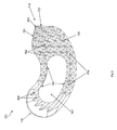
- a TLIF spacer 100 is provided that includes an insertion end 110 and an engagement end 115, the insertion end 110 preferably forming a bullet-nose 112 or having some other tapered geometry for enhancing the ease of insertion and/or for applying a distraction force to the two vertebral bodies between which the implant 100 is configured to be inserted.
- the implant 100 further includes a first main or superior surface 120 that is configured for contacting the inferior endplate of a superior vertebral body and a second main or inferior surface 125 that is configured for contacting the superior endplate of an inferior vertebral body.
- One or more walls 130 on anterior and posterior sides extend between the superior and inferior surfaces 120, 125 and enclose an axial bore 140 that extends through both the superior and inferior surfaces 120, 125.
- the axial bore 140 is configured to house a bone graft 190 or other fusion enhancing material.
- One or more lateral windows 150 are disposed in the walls 130 and provide a visibility window for observing the fusion occurring between the vertebral bodies and enhancing the vascularization of the bone graft 190 disposed within the axial bore 140 to assist fusion, as well as to increase the volume of the axial bore 140.
- One or more surface features 145 are provided along interior portions of the walls 130 that form the axial bore 140 to assist in securing the bone graft 190 within the axial bore 140.
- the features 145 can assume the form of one or more ridges extending through the axial bore 140 along the cranial-caudal direction, grooves, or other surface texturing that enhances the friction between the bone graft 190 and the interior of the walls 130 that form the axial bore 140.
- the TLIF spacer 100 has a kidney bean or banana shape having a curvilinear geometry between its insertion and engagement ends 110, 115.
- This shape may be accomplished by having an anterior edge of the superior and inferior surfaces 120, 125 along with the anterior wall 130 be generally concave and a posterior edge of the superior and inferior surfaces 120, 125 along with the posterior wall 130 be generally convex.
- a variety of geometries may be utilized for the implant 100, depending on the desired amount of surface contact between the endplates of the vertebral bodies and the implant 100, the number of implants 100 desired to be implanted within the disc space (e.g., one or two), the approach chosen for the surgery, the desired location of the implant within the disc space (anterior or posterior), or the like.
- Disposed upon the superior surface 120 adjacent the insertion end 110 are a plurality of curvilinear superior ridges 160 that are arranged parallel to one another along the curvature of the TLIF implant 100.
- the superior ridges 160 include two linearly sloped surfaces that meet to form an apex. As the superior ridges 160 extend along their curvilinear path away from the insertion end 110, the superior ridges 160 are interrupted to form a plurality of superior teeth 162. The superior teeth 162 are disposed at the engagement end 115 and along at least a portion of anterior and posterior sides of the axial bore 140. Similarly, disposed upon the inferior surface 125 adjacent the insertion end 110 is a plurality of curvilinear inferior ridges 165 that are arranged parallel to one another along the curvature of the TLIF implant 100.
- the inferior ridges 165 extend along their curvilinear path away from the insertion end 110, the inferior ridges 165 are interrupted to form a plurality of inferior teeth 167.
- the inferior teeth 167 are disposed at the engagement end 115 and on the anterior and posterior sides of the axial bore 140.
- the superior and inferior ridges 160, 165 guide the insertion of the TLIF implant 100 under the compressive forces of the adjacent vertebral bodies, while the superior and inferior teeth 162, 167 assist in the primary fixation of the TLIF implant 100.
- one or more radiopaque markers 170 are included in the TLIF implant 100 for enabling visualization and controlling of the position of the TLIF implant 100 during and after insertion into the disc space.
- the markers 170 are elongated and include a first marker 170A, a second marker 170B, and a third marker 170C.
- the first and second markers 170A, 170B are disposed in the cranial-caudal direction on either side of the lateral window 150 within the anterior wall 130 of the implant 100.
- the third marker 170C is disposed proximate the insertion end 110, with a longitudinal axis thereof extending from the insertion end 110 toward the axial bore 140.
- the engagement end 115 is characterized by the absence of the walls 130 extending fully between the superior and inferior surfaces 120, 125. That is, a slot 135 is formed at the engagement end 115 that extends continuously between and at least partially along the anterior and posterior walls 130.
- a post 180 is positioned within the slot 135, which is spaced apart from the anterior and posterior walls 130 and extends at least partially between the superior and inferior surfaces 120, 125 and serves as an instrument engagement feature. Adequate space is provided by the slot 135 for the engagement portion of an instrument 200 ( Fig. 7 ) to engage the post 180. As shown in Figs.
- the walls 130 disposed between the axial bore 140 and the post 180 include first and second mating surfaces 132, 134 facing the post 180 between which an obtuse angle is formed for providing a pair of mechanical stops to the range of allowable articulation of the implant 100 with respect to the instrument 200.
- the first and second mating surfaces 132, 134 are preferably linear surfaces, but may also be curved or the like. Alternatively, stop pins or the like may be used to limit articulation of the implant 100.
- the post 180 is polygonal in cross-section and includes nine exposed facets 182a-182i arranged around an entire periphery thereof and extending in the cranial-caudal direction between the superior and inferior surfaces 120, 125.
- the facets 182a-182i are configured to enhance the engagement and interaction between the instrument 200 and the implant 100 during the insertion of the implant 100.
- seven of the facets 182a-182f, 182i are flat surfaces, while the remaining two facets 182g-182h are curved surfaces.
- the post 180 may include a different polygonal number of facets 182.
- the post 180 can be cylindrical and thus include zero facets 182, and may include other features for governing the articulation of the implant 100 with respect to the instrument 200 during its insertion.
- the post 180 can include dimples, teeth, surface texturing, grooves, or the like.
- the engagement end 115 of the superior surface 120 terminates in a superior corner 122, which includes superior first and second flat segments 123, 124 originating near the post 180 and converging at an angle disposed proximate the engagement end 115 of the implant 100.
- the engagement end 115 of the inferior surface 125 terminates in an inferior corner 127, which include inferior first and second flat segments 128, 129 originating near the post 180 and converging terminating at an angle disposed proximate the engagement end 115 of the implant 100.
- the superior first flat segment 123 and the inferior first flat segment 128 are configured to be engagable by a portion of the instrument 200, as is described in detail below, to provide a toggle-free connection, as are the superior second flat segment 124 and the inferior second flat segment 129.
- the rims of both the superior and inferior corner segments 122, 127 have a width extending a short distance from the superior and inferior surfaces 120, 125 toward the center of the implant 100. The surfaces of the rims are also flat for enhancing the interaction between the instrument 200 and the implant 100.
- the implant 100 can be formed from a variety of biocompatible materials, including but not limited to titanium, stainless steel, allograft bone, or polymers such as polyaryletheretherketone (PEEK) and polyetherketoneketone (PEKK), titanfoam, porous PEEK, or the like.
- PEEK polyaryletheretherketone
- PEKK polyetherketoneketone
- an instrument 200 that includes a longitudinal axis extending between a proximal end 201 and a distal end 202.
- the instrument 200 includes an elongated cannulated outer member 210 that surrounds an elongated inner member 250.
- the inner member 250 is configured to be translatable with respect to the outer member 210 along the longitudinal axis.
- the instrument 200 can be configured such that the outer member 210 is translatable with respect to the inner member 250 along the longitudinal axis to perform in the same manner.
- the proximal end of the outer member 210 includes a handle portion (not shown) and an actuation mechanism (not shown) for translating the inner member 250 with respect to the outer member 210.
- the distal end of the outer member 210 includes an outer member first arm 220 and an outer member second arm 240 that are separated by a gap 230 that forms the distal portion of the cannula.
- the gap 230 includes a pair of laterally-oriented surfaces 232 on either side of the cannula disposed at the proximal end of the outer member first and second arms 220, 240.
- the laterally-oriented surfaces 232 serve as a stop to the retraction of the inner member 250 with respect to the outer member 210.
- the interior surface of the first arm 220 includes an outer member first arm interior linear taper 222 disposed distal to an outer member first arm interior straight portion 224,while the interior surface of the second arm 240 includes an outer member second arm interior linear taper 242 disposed distal to an outer member second arm interior straight portion 244.
- the first and second arm interior linear tapers 222, 242 combine to form two wedging surfaces.
- a laterally-extending superior exterior flat surface 215 of the outer member 210 is disposed between the distal ends of the outer member first and second arms 220, 240 and the laterally-oriented surfaces 232.
- a laterally-extending inferior exterior flat surface 216 of the outer member 210 is disposed between the distal ends of the outer member first and second arms 220, 240 and the laterally-oriented surfaces 232.
- the laterally-extending superior exterior flat surface 215 and the laterally-extending inferior exterior flat surface 216 are configured to serve as stops to prevent over articulation of the implant 100 by abutting the superior and inferior first flat segments 123, 128 at one end of the articulation range and interacting with the superior and inferior second flat segments 124, 129 at the other end of the articulation range, as is described in detail below.
- the laterally-extending superior and inferior exterior flat surfaces 215, 216 also abut against the superior and inferior first flat segments 123, 128 of the implant 100, or against the superior and inferior second flat segments 124, 129 of the implant 100, during a portion of the implant insertion procedure.
- the inner member 250 includes at its distal end a grasping portion 255 an inner member first arm 260 and an inner member second arm 280 separated by a split 270 that extends through the middle of the inner member 250 along the longitudinal axis from the grasping portion 255 toward the proximal end.
- the interior surface of the grasping portion 255 includes a plurality of engagement surfaces 257 that are configured to complementarily match the polygonal cross sectional geometry of the post 180 of the implant 100 and, thus, engage several of the plurality of facets 182a-182i. In a first preferred embodiment, there are seven engagement surfaces 257a-257g that are configured to engage seven of the nine facets 182a-182i of the post 180.
- the exterior surface of the inner member first arm 260 includes an inner member first arm exterior linear taper 262 disposed distal to an inner member first arm exterior straight portion 264, while the exterior surface of the inner member second arm 280 includes an inner member second arm exterior linear taper 282 disposed distal to an inner member second arm exterior straight portion 284. Disposed between the inner member first arm exterior linear taper 262 and the distal tip of the inner member first arm 260 is an inner member first arm second exterior linear taper 266.
- an inner member second arm second exterior linear taper 286 disposed between the inner member second arm exterior linear taper 282 and the distal tip of the inner member second arm 280.
- an inner member first arm laterally-oriented flat surface 265 and an inner member second arm laterally-oriented flat surface 285 are formed proximal to and adjacent the inner member first arm exterior straight portion 264 and the inner member second arm exterior straight portion 284, respectively, such that a pair of corners are formed therebetween, and such that the inner member first and second arm laterally-oriented flat surfaces 265, 285 face and abut with the laterally-oriented surfaces 232.
- a trial implant 300 that includes geometry and surface features identical or similar to the implant 100 and further includes a lateral hole 310 and a longitudinal hole 320 and, therefore, a complete description of the trial implant is omitted for convenience only and is not limiting.
- the trial implant 300 is formed from a material that is visible under radiographic imaging, such as titanium, stainless steel, or the like.
- the lateral and longitudinal holes 310, 320 when viewed in conjunction with lateral and frontal X-rays, assist in the optimum positioning of the trial implant 300.
- the lateral holes 310 allow the surgeon to center the trial implant 300 with respect to the spinous processes of the vertebral bodies under fluoroscopy.
- the longitudinal hole 320 indicates whether the trial implant 300 has turned, in which case the surgeon will know that more disc material should preferably be removed.
- the lateral and longitudinal holes 310, 320 are shown as being generally circular or cylindrical in the preferred embodiment, but are not so limited.
- the lateral and longitudinal holes 310, 320 may have nearly any size and/or shape, such as rectangular, square, arrow-shaped, and/or triangular that permits visualization of the location of the trial implant 300 under imaging.
- the trial implant 300 is not limited to including the lateral and longitudinal holes 310, 320 or any holes, as location of the trial implant 300 may be visualized via markers or other features that are optically or machine viewable.
- a spinal disc in need of repair or replacement is identified and an at least partial discectomy is performed, preferably via a unilateral transforaminal approach.
- the trial implant 300 is inserted and removed using the instrument 200 to gauge the appropriate size implant 100 for insertion into the disc space.
- the insertion and manipulation of the trial implant 300 using the instrument 200 is identical to the method of inserting and manipulating the implant 100 using the instrument 200, as described below.
- the lateral and longitudinal holes 310, 320 are viewed using lateral and/or frontal X-rays to confirm the appropriate position of the trial implant 300 within the disc space and an implant size is then chosen.
- the trial implant 300 is used for more than simply measuring the height between the vertebral bodies. Since the trial implant 300 articulates and is inserted to the same desired position as the final implant 100, the trial implant 300 may be used to determine whether the desired position of the implant 100 is reachable, whether enough disc material has been removed, and the like.
- the bone graft 190 is then inserted into the axial bore 140 and secured therein via the surface features 145 (if not already preassembled thereto) and the implant 100 is then coupled to the instrument 200 by distracting the outer member 210 with respect to the inner member 250 via the manipulation of the actuation mechanism (not shown) such that the instrument 200 assumes an open configuration, as seen in Figs 7 , 8 , and 10C .
- the grasping portion 255 is then centered around the post 180 and the inner member 250 is partially retracted with respect to the outer member 210 via the manipulation of the actuation mechanism, thereby forcing the pair of corners formed between the inner member first and second arm exterior straight portions 264, 284 and the inner member first and second arm laterally-oriented flat surfaces 265, 285 to slidingly bear against the outer member first and second arm interior linear tapers 222, 242 until the inner member first and second arm exterior straight portions 264, 284 come to bear against the outer member first and second arm interior straight portions 224, 244, while providing the gap 230 between the inner member first and second arm laterally-oriented flat surfaces 265, 285 and the laterally-oriented surfaces 232.
- the grasping portion 255 is collapsed around the post 180 such that the engagement surfaces 257a-g come into contact against the plurality of facets 182a-i of the post 180 and such that the post 180 is provisionally captured by the grasping portion 255, as shown in Fig. 9C , with the inner member first arm second exterior linear taper 286 bearing against the second linear surface 134.
- the implant 100 is secured to the instrument but the post 180 is capable of rotation with respect to the grasping portion 255 but is prevented from exiting from the grasping portion 255.
- 9A, 9B , 10A, and 10B is achieved by fully retracting the inner member 250 with respect to the outer member 210 via the continued manipulation of the actuation mechanism, thereby forcing the outer member first arm interior linear taper 222 and the outer member second arm interior linear taper 242 to come to bear against the inner member first arm exterior linear taper 262 and the inner member second arm exterior linear taper 282, respectively, thereby closing the gap 230, and finally locking the implant 100 to the instrument 200 while preventing any portions of the inner member first and second arms 260, 280 from separating under force from one another across the split 270 due to the contact between the outer member first and second arm interior linear tapers 222, 242 and the inner member first and second arm exterior linear tapers 262, 282.
- the handle portion of the instrument 200 is grasped and the insertion end 110 of the implant is inserted into the transforaminal window created during the discectomy procedure until the bullet nose 112 enters the disc space and begins to distract the adjacent vertebral bodies and the distal end of the superior and inferior ridges 160, 165 make contact with the inferior surface of the superior vertebral body and the superior surface of the inferior vertebral body, respectively.
- Gentle hammer blows or other impaction forces are administered to the proximal end 201 of the instrument 200 to urge the implant 100 at least partially into the disc space.
- Toggling is prevented between the implant 100 and the instrument 200 during the delivery of impaction forces due to the abutment of (1) the superior and inferior first flat segments 123, 128 with the superior and inferior exterior flat surfaces 215, 216 and/or (2) the second linear surface 134 with the first arm second linear taper 286 and/or (3) the plurality of facets 182a-i of the post 180 with the engagement surface 257a-f when the instrument 200 is in its finally locked configuration with respect to the implant 100. Any of these abutments alone or in combination preferably prevent toggling between the implant 100 and the instrument 200 in the finally locked configuration.
- the inner member 250 is advanced with respect to the outer member 210 such that the instrument reassumes its provisionally locked configuration with respect to the implant 100, in which the implant 100 is coupled to the instrument but the post 180 is capable of rotation with respect to the grasping portion 255.
- the post 180 and, hence, the implant 100 rotates with respect to the grasping portion 255 within a range restricted by the stops provided by the interaction between the inner member second arm second exterior linear taper 286 bearing against the second linear surface 134 (the starting configuration of the insertion method) and the inner member first arm second exterior linear taper 266 bearing against the first linear surface 132 (at maximum angulation).
- the angle of the shaft of the instrument 200 with respect to the disc space is maintained constant, as all of the action performed to articulate the implant 100 is undertaken by the implant 100 itself as the gentle impaction forces drive the implant 100 into its desired final position guided by the superior and inferior ridges 160, 165, with no active turning of the implant necessary.
- the implant 100 Upon contact between the inner member first arm second exterior linear taper 266 and the first linear surface 132, the implant 100 is at or near its desired final positioning interior to the disc space.
- the implant 100 can be repositioned as necessary by again finally locking the implant 100 to the instrument 200, by retracting the inner member 250 distally with respect to the outer member 210, and manipulating the handle of the instrument 200 until the optimum final positioning of the implant 100 is achieved with respect to the disc space while viewing the position of the markers 170 under fluoroscopic imaging.
- the arrangement of the markers 170 enables a single radiographic image, e.g., a lateral image, to be used to determine the precise position of the implant 100 with respect to the disc space.
- the implant 100 is then released from the instrument 200 by manipulating the actuation mechanism until the instrument 200 assumes its open configuration, as described previously, and the grasping portion 255 no longer contacts the post 180.
- the compression forces between the vertebral endplates and the superior and inferior surfaces 120, 125 maintain the implant 100 in place as the instrument 200 is removed from the disc space and the patient's body.
- the insertion and removal of the trial implant 300 may cause the formation of grooves in the adjacent endplates of the superior and inferior vertebral bodies due to the inclusion on the superior and inferior surfaces of the trial implant 300 of superior and inferior ridges that are identical to the superior and inferior ridges 160, 165 of the implant 100.
- the formation of such grooves in the adjacent endplates of the superior and inferior vertebral bodies, while not required for insertion of the implant 100, may assist in easing the insertion of the implant 100 using the instrument 200 via the guided mating of the superior and inferior ridges 160, 165 with the grooves formed previously by the trial implant 300.
- an interbody spacer configured for insertion via a transforaminal path
- implants may be utilized, such as total disc replacements and nucleus replacement devices, by simply configuring such implants to include an appropriately faceted post for an instrument engagement feature and, optionally, the stops and toggle-free bearing surfaces described herein.
- the implant 100 is not limited to a banana or kidney bean shape, but may assume any geometry that can be accommodated within the disc space.
- a range of angular approaches to the disc space may be utilized where an elongated implant is desired to be manipulated or pivoted once it has been delivered along a straight path into the disc space, such as posterior-lateral approaches, translateral, and direct lateral procedures.
- the non-toggling interface between the implant 100 and the instrument 200 during the delivery of impaction forces that is provided by the interaction and abutment of the superior and inferior first flat segments 123,128 with the laterally extending superior and inferior exterior flat surfaces 215, 216, as well as the interaction and abutment of the superior and inferior second flat segments 124, 129 with the laterally-extending superior and inferior exterior flat surfaces 215, 216, can also be provided with nonlinear abutment surfaces. As long as the surfaces mate or are able to abut one another when the instrument assumes its finally locked configuration, a non-toggling interface can be provided.
- the articulation stops that prevent over articulation of the implant 100 with respect to the instrument 200 that are embodied by the first and second linear surfaces 132, 134, and the range of articulation provided by the obtuse angle disposed therebetween, can be provided by a variety of angles which can be tailored specifically to a desired articulation range for a given application, and therefore does not necessarily need to be obtuse.
- the first and second linear surfaces 132, 134, as well as the inner member first and second arm second exterior linear tapers 266, 286 that are abutted thereagainst need not be linear surfaces.
- any mating abutment surfaces will suffice between 132 and 266 and between 134 and 286 for the purposes of limiting the articulation range.
- an embodiment may be envisioned in which the obtuse angle is removed between the first and second linear surfaces 132, 134 such that a single abutment surface is provided that can limit the range of articulation by being abuttable by both the first and second arm second exterior linear tapers 266, 286 and, further, does not need to be linear as long as it provides a mating abutment surface to the geometry chosen for the first and second arm second exterior linear tapers 266, 286.
Landscapes
- Health & Medical Sciences (AREA)
- Engineering & Computer Science (AREA)
- Biomedical Technology (AREA)
- Orthopedic Medicine & Surgery (AREA)
- Transplantation (AREA)
- Oral & Maxillofacial Surgery (AREA)
- Cardiology (AREA)
- Neurology (AREA)
- Heart & Thoracic Surgery (AREA)
- Vascular Medicine (AREA)
- Life Sciences & Earth Sciences (AREA)
- Animal Behavior & Ethology (AREA)
- General Health & Medical Sciences (AREA)
- Public Health (AREA)
- Veterinary Medicine (AREA)
- Physical Education & Sports Medicine (AREA)
- Prostheses (AREA)
- Surgical Instruments (AREA)
Priority Applications (1)
| Application Number | Priority Date | Filing Date | Title |
|---|---|---|---|
| EP15170437.6A EP2939639B1 (fr) | 2009-11-05 | 2009-11-05 | Implant rachidien auto-pivotant et instrumentations associées |
Applications Claiming Priority (3)
| Application Number | Priority Date | Filing Date | Title |
|---|---|---|---|
| EP15170437.6A EP2939639B1 (fr) | 2009-11-05 | 2009-11-05 | Implant rachidien auto-pivotant et instrumentations associées |
| EP09752956.4A EP2496185B1 (fr) | 2009-11-05 | 2009-11-05 | Implant rachidien auto-rotatif et instruments associés |
| PCT/US2009/063371 WO2011056172A1 (fr) | 2009-11-05 | 2009-11-05 | Implant rachidien auto-rotatif et instruments associés |
Related Parent Applications (1)
| Application Number | Title | Priority Date | Filing Date |
|---|---|---|---|
| EP09752956.4A Division EP2496185B1 (fr) | 2009-11-05 | 2009-11-05 | Implant rachidien auto-rotatif et instruments associés |
Publications (2)
| Publication Number | Publication Date |
|---|---|
| EP2939639A1 true EP2939639A1 (fr) | 2015-11-04 |
| EP2939639B1 EP2939639B1 (fr) | 2016-09-07 |
Family
ID=42562689
Family Applications (2)
| Application Number | Title | Priority Date | Filing Date |
|---|---|---|---|
| EP15170437.6A Active EP2939639B1 (fr) | 2009-11-05 | 2009-11-05 | Implant rachidien auto-pivotant et instrumentations associées |
| EP09752956.4A Active EP2496185B1 (fr) | 2009-11-05 | 2009-11-05 | Implant rachidien auto-rotatif et instruments associés |
Family Applications After (1)
| Application Number | Title | Priority Date | Filing Date |
|---|---|---|---|
| EP09752956.4A Active EP2496185B1 (fr) | 2009-11-05 | 2009-11-05 | Implant rachidien auto-rotatif et instruments associés |
Country Status (8)
| Country | Link |
|---|---|
| EP (2) | EP2939639B1 (fr) |
| JP (1) | JP5683026B2 (fr) |
| KR (1) | KR101613767B1 (fr) |
| CN (1) | CN102647961B (fr) |
| AU (1) | AU2009354956B2 (fr) |
| BR (1) | BR112012010460A2 (fr) |
| CA (1) | CA2779438C (fr) |
| WO (1) | WO2011056172A1 (fr) |
Cited By (1)
| Publication number | Priority date | Publication date | Assignee | Title |
|---|---|---|---|---|
| EP3488826A1 (fr) * | 2017-11-27 | 2019-05-29 | Titan Spine, Inc. | Implant rotatif et instruments associés |
Families Citing this family (26)
| Publication number | Priority date | Publication date | Assignee | Title |
|---|---|---|---|---|
| US9028553B2 (en) | 2009-11-05 | 2015-05-12 | DePuy Synthes Products, Inc. | Self-pivoting spinal implant and associated instrumentation |
| EP2547292B1 (fr) | 2010-03-16 | 2019-04-24 | Pinnacle Spine Group, LLC | Implants intervertébraux et systèmes d'implantation d'un greffon |
| US9233006B2 (en) | 2010-06-15 | 2016-01-12 | Zyga Technology, Inc. | Systems and methods for facet joint treatment |
| US9132021B2 (en) | 2011-10-07 | 2015-09-15 | Pioneer Surgical Technology, Inc. | Intervertebral implant |
| US9220607B2 (en) * | 2011-10-28 | 2015-12-29 | Warsaw Oorthopedic, Inc. | Pivotable interbody implant system |
| US9380932B1 (en) | 2011-11-02 | 2016-07-05 | Pinnacle Spine Group, Llc | Retractor devices for minimally invasive access to the spine |
| FR2986416B1 (fr) * | 2012-02-08 | 2014-12-19 | Implanet | Implant intersomatique et outil pour installer un tel implant |
| WO2014022779A1 (fr) * | 2012-08-02 | 2014-02-06 | Beacon Biomedical, Llc | Cage latérale pivotante et outil d'insertion |
| EP2919717A1 (fr) * | 2012-11-15 | 2015-09-23 | Zyga Technology, Inc. | Systèmes et procédés de traitement de facettes articulaires |
| US10022245B2 (en) | 2012-12-17 | 2018-07-17 | DePuy Synthes Products, Inc. | Polyaxial articulating instrument |
| CN103142331B (zh) * | 2013-02-26 | 2016-01-06 | 广州聚生生物科技有限公司 | 寰枢侧块关节融合器 |
| WO2014159739A1 (fr) | 2013-03-14 | 2014-10-02 | Pinnacle Spine Group, Llc | Implants intersomatiques et systèmes de pose de greffe |
| CN103622767A (zh) * | 2013-12-11 | 2014-03-12 | 广州聚生生物科技有限公司 | 经椎间孔入路的腰椎融合器 |
| US10478313B1 (en) | 2014-01-10 | 2019-11-19 | Nuvasive, Inc. | Spinal fusion implant and related methods |
| CN104490495B (zh) * | 2014-11-24 | 2017-02-22 | 创生医疗器械(中国)有限公司 | Tlif融合器 |
| CN104814816A (zh) * | 2015-05-20 | 2015-08-05 | 上海长征医院 | 自稳型极外侧入路椎间融合器 |
| ITUA20164406A1 (it) * | 2016-06-15 | 2017-12-15 | Medacta Int Sa | Dispositivo ed un kit per il posizionamento di un impianto di fusione intervertebrale |
| US10966843B2 (en) | 2017-07-18 | 2021-04-06 | DePuy Synthes Products, Inc. | Implant inserters and related methods |
| US11045331B2 (en) | 2017-08-14 | 2021-06-29 | DePuy Synthes Products, Inc. | Intervertebral implant inserters and related methods |
| JP7521152B2 (ja) * | 2017-09-08 | 2024-07-24 | エクスタント メディカル ホールディングス,インコーポレイテッド. | 椎間インプラント、器具、及び方法 |
| USD907771S1 (en) | 2017-10-09 | 2021-01-12 | Pioneer Surgical Technology, Inc. | Intervertebral implant |
| JP6965171B2 (ja) * | 2018-02-02 | 2021-11-10 | 日本特殊陶業株式会社 | 骨手術用トライアル |
| IT202000001210A1 (it) * | 2020-01-22 | 2021-07-22 | Sps S R L | Gabbia intersomatica per stabilizzazione vertebrale |
| CN111529134A (zh) * | 2020-04-29 | 2020-08-14 | 陕西增材制造研究院有限责任公司 | 一种多孔椎间融合器及其加工方法 |
| JP2024508987A (ja) * | 2021-03-08 | 2024-02-28 | ラマルティーナ クラウディオ | 脊椎固定術のためのケージ |
| FR3129078A1 (fr) * | 2021-11-17 | 2023-05-19 | Safe | Ensemble comprenant une cage intersomatique et son dispositif de mise en place |
Citations (7)
| Publication number | Priority date | Publication date | Assignee | Title |
|---|---|---|---|---|
| US20060106460A1 (en) * | 2001-05-03 | 2006-05-18 | Synthes (Usa) | Intervertebral implant for transforaminal posterior lumbar interbody fusion procedure |
| US20060229627A1 (en) * | 2004-10-29 | 2006-10-12 | Hunt Margaret M | Variable angle spinal surgery instrument |
| WO2007070751A1 (fr) * | 2005-12-12 | 2007-06-21 | Warsaw Orthopedic, Inc. | Implant vertebral et instrument de pose |
| US20070282441A1 (en) * | 2006-05-19 | 2007-12-06 | Katie Stream | Spinal Stabilization Device and Methods |
| WO2008036636A2 (fr) * | 2006-09-18 | 2008-03-27 | Alpinespine Llc | Espaceur vertébral pivotant |
| US20080119935A1 (en) * | 2006-11-17 | 2008-05-22 | Luis Marquez Alvarez | Intersomatic cage, clamp for manipulating it and procedure for inserting the intersomatic cage between vertebrae |
| US20080306488A1 (en) * | 2007-06-07 | 2008-12-11 | Moti Altarac | Inserter for a spinal implant |
Family Cites Families (8)
| Publication number | Priority date | Publication date | Assignee | Title |
|---|---|---|---|---|
| US7828849B2 (en) * | 2003-02-03 | 2010-11-09 | Warsaw Orthopedic, Inc. | Expanding interbody implant and articulating inserter and method |
| US7806932B2 (en) * | 2003-08-01 | 2010-10-05 | Zimmer Spine, Inc. | Spinal implant |
| JP4443570B2 (ja) * | 2003-10-29 | 2010-03-31 | サージビュー | 経椎間孔アプローチによる腰椎固定のための椎体間ケージ及びそのケージ支持装置 |
| US8157845B2 (en) * | 2006-03-22 | 2012-04-17 | Beacon Biomedical, Llc | Pivotable vetrebral spacer |
| US8100975B2 (en) | 2006-08-11 | 2012-01-24 | Warsaw Orthopedic, Inc. | Intervertebral implants with attachable flanges and methods of use |
| US20080077247A1 (en) | 2006-09-22 | 2008-03-27 | Alphatec Spine, Inc. | Spinal spacer |
| FR2916956B1 (fr) * | 2007-06-08 | 2012-12-14 | Ldr Medical | Cage intersomatique,prothese intervertebrale,dispositif d'ancrage et instrumentation d'implantation |
| US8491598B2 (en) * | 2008-03-03 | 2013-07-23 | Us Spine, Inc. | Surgical positioning assembly and associated spinal implant device and surgical methods |
-
2009
- 2009-11-05 CA CA2779438A patent/CA2779438C/fr not_active Expired - Fee Related
- 2009-11-05 EP EP15170437.6A patent/EP2939639B1/fr active Active
- 2009-11-05 BR BR112012010460A patent/BR112012010460A2/pt not_active Application Discontinuation
- 2009-11-05 WO PCT/US2009/063371 patent/WO2011056172A1/fr active Application Filing
- 2009-11-05 KR KR1020127014306A patent/KR101613767B1/ko active IP Right Grant
- 2009-11-05 EP EP09752956.4A patent/EP2496185B1/fr active Active
- 2009-11-05 JP JP2012537848A patent/JP5683026B2/ja active Active
- 2009-11-05 AU AU2009354956A patent/AU2009354956B2/en active Active
- 2009-11-05 CN CN200980162861.7A patent/CN102647961B/zh active Active
Patent Citations (7)
| Publication number | Priority date | Publication date | Assignee | Title |
|---|---|---|---|---|
| US20060106460A1 (en) * | 2001-05-03 | 2006-05-18 | Synthes (Usa) | Intervertebral implant for transforaminal posterior lumbar interbody fusion procedure |
| US20060229627A1 (en) * | 2004-10-29 | 2006-10-12 | Hunt Margaret M | Variable angle spinal surgery instrument |
| WO2007070751A1 (fr) * | 2005-12-12 | 2007-06-21 | Warsaw Orthopedic, Inc. | Implant vertebral et instrument de pose |
| US20070282441A1 (en) * | 2006-05-19 | 2007-12-06 | Katie Stream | Spinal Stabilization Device and Methods |
| WO2008036636A2 (fr) * | 2006-09-18 | 2008-03-27 | Alpinespine Llc | Espaceur vertébral pivotant |
| US20080119935A1 (en) * | 2006-11-17 | 2008-05-22 | Luis Marquez Alvarez | Intersomatic cage, clamp for manipulating it and procedure for inserting the intersomatic cage between vertebrae |
| US20080306488A1 (en) * | 2007-06-07 | 2008-12-11 | Moti Altarac | Inserter for a spinal implant |
Cited By (2)
| Publication number | Priority date | Publication date | Assignee | Title |
|---|---|---|---|---|
| EP3488826A1 (fr) * | 2017-11-27 | 2019-05-29 | Titan Spine, Inc. | Implant rotatif et instruments associés |
| US10973658B2 (en) | 2017-11-27 | 2021-04-13 | Titan Spine, Inc. | Rotating implant and associated instrumentation |
Also Published As
| Publication number | Publication date |
|---|---|
| CN102647961A (zh) | 2012-08-22 |
| JP2013509940A (ja) | 2013-03-21 |
| WO2011056172A1 (fr) | 2011-05-12 |
| EP2496185B1 (fr) | 2015-06-10 |
| CA2779438A1 (fr) | 2011-05-12 |
| CN102647961B (zh) | 2015-11-25 |
| JP5683026B2 (ja) | 2015-03-11 |
| KR20120093324A (ko) | 2012-08-22 |
| AU2009354956B2 (en) | 2015-02-19 |
| EP2939639B1 (fr) | 2016-09-07 |
| EP2496185A1 (fr) | 2012-09-12 |
| AU2009354956A1 (en) | 2012-05-24 |
| KR101613767B1 (ko) | 2016-04-19 |
| CA2779438C (fr) | 2016-03-01 |
| BR112012010460A2 (pt) | 2017-08-08 |
Similar Documents
| Publication | Publication Date | Title |
|---|---|---|
| US11712349B2 (en) | Self-pivoting spinal implant and associated instrumentation | |
| EP2939639B1 (fr) | Implant rachidien auto-pivotant et instrumentations associées | |
| US9737412B2 (en) | Intervertebral implant having extendable bone fixation members | |
| US20230112704A1 (en) | Spinal fusion devices, systems and methods | |
| EP2967907B1 (fr) | Implant intervertébral extensible | |
| CA2555876C (fr) | Systemes et procedes de chirurgie vertebrale | |
| AU2014204443B2 (en) | Systems and methods for spinal surgery |
Legal Events
| Date | Code | Title | Description |
|---|---|---|---|
| PUAI | Public reference made under article 153(3) epc to a published international application that has entered the european phase |
Free format text: ORIGINAL CODE: 0009012 |
|
| 17P | Request for examination filed |
Effective date: 20150603 |
|
| AC | Divisional application: reference to earlier application |
Ref document number: 2496185 Country of ref document: EP Kind code of ref document: P |
|
| AK | Designated contracting states |
Kind code of ref document: A1 Designated state(s): AT BE BG CH CY CZ DE DK EE ES FI FR GB GR HR HU IE IS IT LI LT LU LV MC MK MT NL NO PL PT RO SE SI SK SM TR |
|
| GRAP | Despatch of communication of intention to grant a patent |
Free format text: ORIGINAL CODE: EPIDOSNIGR1 |
|
| RIC1 | Information provided on ipc code assigned before grant |
Ipc: A61F 2/30 20060101ALI20160303BHEP Ipc: A61F 2/44 20060101ALI20160303BHEP Ipc: A61F 2/46 20060101AFI20160303BHEP Ipc: A61F 2/28 20060101ALI20160303BHEP |
|
| INTG | Intention to grant announced |
Effective date: 20160321 |
|
| GRAS | Grant fee paid |
Free format text: ORIGINAL CODE: EPIDOSNIGR3 |
|
| GRAA | (expected) grant |
Free format text: ORIGINAL CODE: 0009210 |
|
| AC | Divisional application: reference to earlier application |
Ref document number: 2496185 Country of ref document: EP Kind code of ref document: P |
|
| AK | Designated contracting states |
Kind code of ref document: B1 Designated state(s): AT BE BG CH CY CZ DE DK EE ES FI FR GB GR HR HU IE IS IT LI LT LU LV MC MK MT NL NO PL PT RO SE SI SK SM TR |
|
| REG | Reference to a national code |
Ref country code: GB Ref legal event code: FG4D |
|
| REG | Reference to a national code |
Ref country code: CH Ref legal event code: EP |
|
| REG | Reference to a national code |
Ref country code: CH Ref legal event code: NV Representative=s name: E. BLUM AND CO. AG PATENT- UND MARKENANWAELTE , CH |
|
| REG | Reference to a national code |
Ref country code: IE Ref legal event code: FG4D |
|
| REG | Reference to a national code |
Ref country code: AT Ref legal event code: REF Ref document number: 826144 Country of ref document: AT Kind code of ref document: T Effective date: 20161015 |
|
| REG | Reference to a national code |
Ref country code: DE Ref legal event code: R096 Ref document number: 602009041083 Country of ref document: DE |
|
| REG | Reference to a national code |
Ref country code: LT Ref legal event code: MG4D |
|
| REG | Reference to a national code |
Ref country code: NL Ref legal event code: MP Effective date: 20160907 |
|
| PG25 | Lapsed in a contracting state [announced via postgrant information from national office to epo] |
Ref country code: LT Free format text: LAPSE BECAUSE OF FAILURE TO SUBMIT A TRANSLATION OF THE DESCRIPTION OR TO PAY THE FEE WITHIN THE PRESCRIBED TIME-LIMIT Effective date: 20160907 Ref country code: HR Free format text: LAPSE BECAUSE OF FAILURE TO SUBMIT A TRANSLATION OF THE DESCRIPTION OR TO PAY THE FEE WITHIN THE PRESCRIBED TIME-LIMIT Effective date: 20160907 Ref country code: NO Free format text: LAPSE BECAUSE OF FAILURE TO SUBMIT A TRANSLATION OF THE DESCRIPTION OR TO PAY THE FEE WITHIN THE PRESCRIBED TIME-LIMIT Effective date: 20161207 Ref country code: FI Free format text: LAPSE BECAUSE OF FAILURE TO SUBMIT A TRANSLATION OF THE DESCRIPTION OR TO PAY THE FEE WITHIN THE PRESCRIBED TIME-LIMIT Effective date: 20160907 |
|
| REG | Reference to a national code |
Ref country code: AT Ref legal event code: MK05 Ref document number: 826144 Country of ref document: AT Kind code of ref document: T Effective date: 20160907 |
|
| PG25 | Lapsed in a contracting state [announced via postgrant information from national office to epo] |
Ref country code: GR Free format text: LAPSE BECAUSE OF FAILURE TO SUBMIT A TRANSLATION OF THE DESCRIPTION OR TO PAY THE FEE WITHIN THE PRESCRIBED TIME-LIMIT Effective date: 20161208 Ref country code: NL Free format text: LAPSE BECAUSE OF FAILURE TO SUBMIT A TRANSLATION OF THE DESCRIPTION OR TO PAY THE FEE WITHIN THE PRESCRIBED TIME-LIMIT Effective date: 20160907 Ref country code: LV Free format text: LAPSE BECAUSE OF FAILURE TO SUBMIT A TRANSLATION OF THE DESCRIPTION OR TO PAY THE FEE WITHIN THE PRESCRIBED TIME-LIMIT Effective date: 20160907 Ref country code: BE Free format text: LAPSE BECAUSE OF NON-PAYMENT OF DUE FEES Effective date: 20161130 Ref country code: SE Free format text: LAPSE BECAUSE OF FAILURE TO SUBMIT A TRANSLATION OF THE DESCRIPTION OR TO PAY THE FEE WITHIN THE PRESCRIBED TIME-LIMIT Effective date: 20160907 Ref country code: ES Free format text: LAPSE BECAUSE OF FAILURE TO SUBMIT A TRANSLATION OF THE DESCRIPTION OR TO PAY THE FEE WITHIN THE PRESCRIBED TIME-LIMIT Effective date: 20160907 |
|
| PG25 | Lapsed in a contracting state [announced via postgrant information from national office to epo] |
Ref country code: EE Free format text: LAPSE BECAUSE OF FAILURE TO SUBMIT A TRANSLATION OF THE DESCRIPTION OR TO PAY THE FEE WITHIN THE PRESCRIBED TIME-LIMIT Effective date: 20160907 Ref country code: RO Free format text: LAPSE BECAUSE OF FAILURE TO SUBMIT A TRANSLATION OF THE DESCRIPTION OR TO PAY THE FEE WITHIN THE PRESCRIBED TIME-LIMIT Effective date: 20160907 |
|
| PG25 | Lapsed in a contracting state [announced via postgrant information from national office to epo] |
Ref country code: CZ Free format text: LAPSE BECAUSE OF FAILURE TO SUBMIT A TRANSLATION OF THE DESCRIPTION OR TO PAY THE FEE WITHIN THE PRESCRIBED TIME-LIMIT Effective date: 20160907 Ref country code: SK Free format text: LAPSE BECAUSE OF FAILURE TO SUBMIT A TRANSLATION OF THE DESCRIPTION OR TO PAY THE FEE WITHIN THE PRESCRIBED TIME-LIMIT Effective date: 20160907 Ref country code: BG Free format text: LAPSE BECAUSE OF FAILURE TO SUBMIT A TRANSLATION OF THE DESCRIPTION OR TO PAY THE FEE WITHIN THE PRESCRIBED TIME-LIMIT Effective date: 20161207 Ref country code: AT Free format text: LAPSE BECAUSE OF FAILURE TO SUBMIT A TRANSLATION OF THE DESCRIPTION OR TO PAY THE FEE WITHIN THE PRESCRIBED TIME-LIMIT Effective date: 20160907 Ref country code: SM Free format text: LAPSE BECAUSE OF FAILURE TO SUBMIT A TRANSLATION OF THE DESCRIPTION OR TO PAY THE FEE WITHIN THE PRESCRIBED TIME-LIMIT Effective date: 20160907 Ref country code: BE Free format text: LAPSE BECAUSE OF FAILURE TO SUBMIT A TRANSLATION OF THE DESCRIPTION OR TO PAY THE FEE WITHIN THE PRESCRIBED TIME-LIMIT Effective date: 20160907 Ref country code: PT Free format text: LAPSE BECAUSE OF FAILURE TO SUBMIT A TRANSLATION OF THE DESCRIPTION OR TO PAY THE FEE WITHIN THE PRESCRIBED TIME-LIMIT Effective date: 20170109 Ref country code: IS Free format text: LAPSE BECAUSE OF FAILURE TO SUBMIT A TRANSLATION OF THE DESCRIPTION OR TO PAY THE FEE WITHIN THE PRESCRIBED TIME-LIMIT Effective date: 20170107 Ref country code: PL Free format text: LAPSE BECAUSE OF FAILURE TO SUBMIT A TRANSLATION OF THE DESCRIPTION OR TO PAY THE FEE WITHIN THE PRESCRIBED TIME-LIMIT Effective date: 20160907 |
|
| REG | Reference to a national code |
Ref country code: DE Ref legal event code: R097 Ref document number: 602009041083 Country of ref document: DE |
|
| PG25 | Lapsed in a contracting state [announced via postgrant information from national office to epo] |
Ref country code: IT Free format text: LAPSE BECAUSE OF FAILURE TO SUBMIT A TRANSLATION OF THE DESCRIPTION OR TO PAY THE FEE WITHIN THE PRESCRIBED TIME-LIMIT Effective date: 20160907 |
|
| PLBE | No opposition filed within time limit |
Free format text: ORIGINAL CODE: 0009261 |
|
| STAA | Information on the status of an ep patent application or granted ep patent |
Free format text: STATUS: NO OPPOSITION FILED WITHIN TIME LIMIT |
|
| PG25 | Lapsed in a contracting state [announced via postgrant information from national office to epo] |
Ref country code: DK Free format text: LAPSE BECAUSE OF FAILURE TO SUBMIT A TRANSLATION OF THE DESCRIPTION OR TO PAY THE FEE WITHIN THE PRESCRIBED TIME-LIMIT Effective date: 20160907 |
|
| REG | Reference to a national code |
Ref country code: DE Ref legal event code: R082 Ref document number: 602009041083 Country of ref document: DE Representative=s name: KLUNKER IP PATENTANWAELTE PARTG MBB, DE |
|
| 26N | No opposition filed |
Effective date: 20170608 |
|
| REG | Reference to a national code |
Ref country code: IE Ref legal event code: MM4A |
|
| REG | Reference to a national code |
Ref country code: FR Ref legal event code: ST Effective date: 20170731 |
|
| PG25 | Lapsed in a contracting state [announced via postgrant information from national office to epo] |
Ref country code: SI Free format text: LAPSE BECAUSE OF FAILURE TO SUBMIT A TRANSLATION OF THE DESCRIPTION OR TO PAY THE FEE WITHIN THE PRESCRIBED TIME-LIMIT Effective date: 20160907 |
|
| PG25 | Lapsed in a contracting state [announced via postgrant information from national office to epo] |
Ref country code: LU Free format text: LAPSE BECAUSE OF NON-PAYMENT OF DUE FEES Effective date: 20161130 |
|
| PG25 | Lapsed in a contracting state [announced via postgrant information from national office to epo] |
Ref country code: FR Free format text: LAPSE BECAUSE OF NON-PAYMENT OF DUE FEES Effective date: 20161130 |
|
| PG25 | Lapsed in a contracting state [announced via postgrant information from national office to epo] |
Ref country code: IE Free format text: LAPSE BECAUSE OF NON-PAYMENT OF DUE FEES Effective date: 20161105 |
|
| PG25 | Lapsed in a contracting state [announced via postgrant information from national office to epo] |
Ref country code: HU Free format text: LAPSE BECAUSE OF FAILURE TO SUBMIT A TRANSLATION OF THE DESCRIPTION OR TO PAY THE FEE WITHIN THE PRESCRIBED TIME-LIMIT; INVALID AB INITIO Effective date: 20091105 |
|
| PG25 | Lapsed in a contracting state [announced via postgrant information from national office to epo] |
Ref country code: MK Free format text: LAPSE BECAUSE OF FAILURE TO SUBMIT A TRANSLATION OF THE DESCRIPTION OR TO PAY THE FEE WITHIN THE PRESCRIBED TIME-LIMIT Effective date: 20160907 Ref country code: CY Free format text: LAPSE BECAUSE OF FAILURE TO SUBMIT A TRANSLATION OF THE DESCRIPTION OR TO PAY THE FEE WITHIN THE PRESCRIBED TIME-LIMIT Effective date: 20160907 Ref country code: MC Free format text: LAPSE BECAUSE OF FAILURE TO SUBMIT A TRANSLATION OF THE DESCRIPTION OR TO PAY THE FEE WITHIN THE PRESCRIBED TIME-LIMIT Effective date: 20160907 |
|
| PG25 | Lapsed in a contracting state [announced via postgrant information from national office to epo] |
Ref country code: MT Free format text: LAPSE BECAUSE OF NON-PAYMENT OF DUE FEES Effective date: 20161105 |
|
| PG25 | Lapsed in a contracting state [announced via postgrant information from national office to epo] |
Ref country code: TR Free format text: LAPSE BECAUSE OF FAILURE TO SUBMIT A TRANSLATION OF THE DESCRIPTION OR TO PAY THE FEE WITHIN THE PRESCRIBED TIME-LIMIT Effective date: 20160907 |
|
| PGFP | Annual fee paid to national office [announced via postgrant information from national office to epo] |
Ref country code: GB Payment date: 20230928 Year of fee payment: 15 |
|
| PGFP | Annual fee paid to national office [announced via postgrant information from national office to epo] |
Ref country code: DE Payment date: 20230929 Year of fee payment: 15 |
|
| PGFP | Annual fee paid to national office [announced via postgrant information from national office to epo] |
Ref country code: CH Payment date: 20240127 Year of fee payment: 15 |