EP2939237B1 - Optical media servo tracking - Google Patents
Optical media servo tracking Download PDFInfo
- Publication number
- EP2939237B1 EP2939237B1 EP13815242.6A EP13815242A EP2939237B1 EP 2939237 B1 EP2939237 B1 EP 2939237B1 EP 13815242 A EP13815242 A EP 13815242A EP 2939237 B1 EP2939237 B1 EP 2939237B1
- Authority
- EP
- European Patent Office
- Prior art keywords
- pickup unit
- optical pickup
- tracking signal
- relative position
- optical
- Prior art date
- Legal status (The legal status is an assumption and is not a legal conclusion. Google has not performed a legal analysis and makes no representation as to the accuracy of the status listed.)
- Active
Links
Images


Classifications
-
- G—PHYSICS
- G11—INFORMATION STORAGE
- G11B—INFORMATION STORAGE BASED ON RELATIVE MOVEMENT BETWEEN RECORD CARRIER AND TRANSDUCER
- G11B7/00—Recording or reproducing by optical means, e.g. recording using a thermal beam of optical radiation by modifying optical properties or the physical structure, reproducing using an optical beam at lower power by sensing optical properties; Record carriers therefor
- G11B7/002—Recording, reproducing or erasing systems characterised by the shape or form of the carrier
- G11B7/003—Recording, reproducing or erasing systems characterised by the shape or form of the carrier with webs, filaments or wires, e.g. belts, spooled tapes or films of quasi-infinite extent
-
- G—PHYSICS
- G11—INFORMATION STORAGE
- G11B—INFORMATION STORAGE BASED ON RELATIVE MOVEMENT BETWEEN RECORD CARRIER AND TRANSDUCER
- G11B7/00—Recording or reproducing by optical means, e.g. recording using a thermal beam of optical radiation by modifying optical properties or the physical structure, reproducing using an optical beam at lower power by sensing optical properties; Record carriers therefor
- G11B7/08—Disposition or mounting of heads or light sources relatively to record carriers
- G11B7/09—Disposition or mounting of heads or light sources relatively to record carriers with provision for moving the light beam or focus plane for the purpose of maintaining alignment of the light beam relative to the record carrier during transducing operation, e.g. to compensate for surface irregularities of the latter or for track following
- G11B7/0901—Disposition or mounting of heads or light sources relatively to record carriers with provision for moving the light beam or focus plane for the purpose of maintaining alignment of the light beam relative to the record carrier during transducing operation, e.g. to compensate for surface irregularities of the latter or for track following for track following only
- G11B7/0906—Differential phase difference systems
Definitions
- This disclosure relates to optical media servo systems.
- Optical tape is a data storage medium. In certain examples, it can take the form of long narrow strips onto which patterns can be written and from which patterns can be read. Optical tape may facilitate higher data transfer rates, greater storage capacity, and reduced access times relative to magnetic tape. Moreover because optical tape is written and read using optical pick up units that do not touch the recording surface of the tape, it may be more durable than magnetic tape.
- US 2003142599 discloses a DPD tracking error generating section that generates a DPD tracking error signal from a plurality of sense signals supplied from an optical sensor.
- a PP tracking error generating section generates a PP tracking error signal from a plurality of sense signals supplied from the optical sensor.
- the amplitude of each of the DPD tracking error signal and PP tracking error signal is adjusted suitably under the control of a CPU.
- the suitably adjusted signals are added by an adder, thereby generating a tracking error signal.
- US 5828637 discloses a servo control device of an optical disk recording and reproducing apparatus which is capable of performing tracking control and sled control by detecting radial shift indicative of a degree of deviation from the center of an objective lens in an optical pick-up unit and by detecting a tilt indicative of the inclination of an optical disk, thereby achieving a good reproducing signal quality.
- JP H11/175989 discloses a tracking control device based on one spot system, which is capable of performing good tracking control without generating any offset in a tracking error signal even when an objective lens is shifted during reproducing.
- This device is provided with a circuit for generating the tracking error signal of a DPD (phase difference detection) system by a signal from a 4-division photodetector and a circuit for generating the tracking error signal of a PP (push-pull) system by the same signal.
- DPD phase difference detection
- PP pushh-pull
- the sum of the low frequency component of the DPD signal obtained during the period of tracing on the phase pit string by an optical spot and the high frequency component of the PP signal obtained during the period of tracing on the groove is generated and, by using this as a tracking error signal, the effect of offset by the shifting of the objective lens is eliminated, and good tracking control is performed.
- JP H05/325234 discloses a stable tracking servo in which the light reflected from an optical disk is received by a photodetector, and the phase difference between diagonal sums of light receiving faces of the photodetector is denoted as a time difference error signal, and the difference signal between two areas divided by a boundary line along the track of the optical disk is denoted as a push-pull error, and these signals are mixed.
- the amplitude value of the push-pull error signal is detected by a level detector, and the extent of attenuation of an attenuator is controlled in accordance with this detection output to vary the mixture ratio of respective signals.
- the mixture ratio of the push-pull error signal and the time difference error signal is properly controlled in accordance with the level of the push-pull error signal at the time of opening the tracking servo, the variance of the gain of the push- pull error signal dependent upon the pit depth is controlled to perform the stable tracking servo.
- tracking servo systems for rewritable optical media position the optical head over the perceived data track based on reference tracking signals generated by the optical pickup unit according to its diffraction properties and the physical format of the media. Because these types of positioning systems typically depend entirely on reference tracking signals and not the actual location of written data, they are subject to track mis-registration due to various disturbances and anomalies, such as the misalignment between mechanical and optical subsystems or variation from optical pickup unit to optical pickup unit. Optical pickup unit to optical pickup unit variation can be particularly apparent, manifesting as track mis-registration, when media is written with one optical pickup unit and read by another.
- rewritable optical media 10 may include land 12 and groove 14. Data may be written to or read from phase change material within the groove 14 as known in the art.
- the land 12 and groove 14 define edges 16, which as explained below can be used for tracking purposes.
- An optical system 18 may include, among other things, an optical pickup unit 20.
- the optical pickup unit 20 may include infrastructure, such as laser diodes, etc., to generate laser beam 22, quadrature photodiode integrated circuit (quad-PDIC) detectors 24, 26, 28, 30, amplifiers 32, 34, 36, 38, sum blocks 40, 42, and difference block 44.
- quadrature photodiode integrated circuit (quad-PDIC) detectors 24, 26, 28, 30, amplifiers 32, 34, 36, 38, sum blocks 40, 42, and difference block 44.
- MPP main push pull
- radial push pull tracking infrastructure 45 The phrase “main push pull” is typically used within the context of optical tape or optical disk media.
- radial push pull is typically used within the context of disk media. From a conceptual standpoint, these phases can be used interchangeably.
- the resulting output can be referred to as a MPP or radial push pull tracking signal.
- the shape of a MPP signal reflects the relative movement between the edges 16 and optical pick up unit 20.
- a MPP signal having the shape of a horizontal line, for example, would indicate that the laser beam 22 is centered between the edges 16.
- a MPP signal having the shape of a sinusoid, for example, would indicate that the laser beam 22 is moving relative to the edges 16.
- Figure 2 shows an example of such a signal.
- the optical system 18 would thus attempt to control the position of the optical pick up unit 20 to minimize this behavior.
- read only optical media 46 may include data marks 48 written in phase change material. (Unlike rewritable optical media 10, the media 46 lacks land and groove. Therefore, edges cannot be used for tracking purposes. Such media therefore falls outside the scope of the independent claims)
- An optical system 50 may include, among other things, an optical pickup unit 52.
- the optical pickup unit 52 may include infrastructure, such as diodes, etc., to generate laser beam 54, quad-PDIC detectors 56, 58, 60, 62, amplifiers 64, 66, 68, 70, sum blocks 72, 74, filters 76, 78, comparators 80, 82, phase detector 84, filters 86, 88, and differential amplifier 90.
- DPD differential phase detection
- the shape of a DPD signal reflects the relative movement between the data marks 48 and optical pick up unit 52.
- a DPD signal having the shape of a horizontal line, for example, would indicate that the laser beam 54 is centered on the data marks 48.
- a DPD signal having the shape of saw teeth, for example, would indicate that the laser beam 54 is moving relative to the data marks 48.
- Figure 4 shows an example of such a signal.
- the optical system 50 would thus attempt to control the position of the optical pick up unit 52 to minimize this behavior.
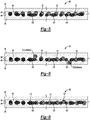
- rewritable optical media 92 such as optical tape, includes land 94 and groove 96.
- the land 94 and groove 96 define edges 98.
- Data marks 100 have been written in phase change material within the groove 96.
- the data marks 100 are not centered between the edges 98. That is, they are offset from the center of the groove 96. Such offset may result from misalignment, mis-calibration, etc. of the optical system used to write the data marks 100 as mentioned above.
- An optical system such as the optical system 18 of Figure 1 , may be used to read the data marks 100.
- the optical system 18 will attempt to center the laser beam 22 between the edges 98-regardless of the location of the data marks 1 00-because it uses MPP or radial push pull tracking technology. This misalignment between the laser beam 22 and data marks 100 may interfere with the data reading process.
- an optical system such as the optical system 50 of Figure 3
- the optical system 50 will attempt to center the laser beam 54 on the data marks 100-regardless of the location of the edges 98-because it uses DPD tracking technology.
- DPD tracking technology does not respond well to high-frequency disturbances.
- the optical tape 92 as it is fed through the optical system 50 may experience high-frequency lateral tape movement (movement perpendicular to the direction of tape motion) relative to the laser beam 54.
- the optical tape 92 may move laterally away from the laser beam 54 more quickly than the DPD tracking technology used by the optical system 50 can correct for such movement, causing the laser beam 54 to jump relative to the data marks 100.
- This disturbance between the laser beam 54 and data marks 100 may interfere with the data reading process.
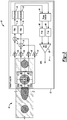
- an optical system 102 includes an optical pickup unit 104, a controller 106, and an optical pickup unit actuator 108. Signals generated by the optical pickup unit 104 are processed by the controller 106 and used by the actuator 108 to position the optical pickup unit 104 relative to optical media.
- the optical media is an optical tape.
- the optical pickup unit 104 may include infrastructure, such as diodes, etc., to generate laser beam 110, quad-PDIC detectors 112, 114, 116, 118, sum block 120, MPP tracking infrastructure 122, high pass filter 124, DPD tracking infrastructure 126, low pass filter 128, and sum block 130.
- the MPP tracking infrastructure 122 is similar to the MPP tracking infrastructure 45 of Figure 1 .
- the DPD tracking infrastructure 126 is similar to the DPD tracking infrastructure 91 of Figure 3 .
- Other optical pickup unit architectures are, of course, also possible.
- the DPD tracking infrastructure 126 and the low pass filter 128 are inactive. Signals generated in response to edges being detected (that is, in response to land and groove structures being detected) from optical media (not shown) by the laser beam 110 are fed to the sum block 120 along with a feedback signal from the actuator 108. The resulting signal is fed to the MPP tracking infrastructure 122. The MPP tracking signal output by the MPP tracking infrastructure 122 may then be used by the controller 106 to control operation of the actuator 108 to attempt to maintain a position of the laser beam 110 centered between edges of the optical media.
- signals generated in response to data being detected from optical media (not shown) by the laser beam 110 are fed to the MPP tracking infrastructure 122 via the sum block 120 and the DPD tracking infrastructure 126.
- Low frequency content of the MPP tracking signal output by the MPP tracking infrastructure 122 may be filtered out by the high pass filter 124.
- frequency content of the MPP tracking signal less than 300 Hz may be filtered out by the high pass filter 124.
- More threshold frequencies may also be used depending on media characteristics and other design parameters. Optimum threshold frequencies may be determined via testing, simulation, etc.
- High-frequency content of the DPD tracking signal output by the DPP tracking infrastructure 126 may be filtered out by the low pass filter 128.
- frequency content of the DPD tracking signal greater than 300 Hz may be filtered out by the low pass filter 128. (As mentioned above, other threshold frequencies may be used.)
- the tracking signals are then fed to sum block 130.
- the resulting hybrid MPP/DPD tracking signal is then used by the controller 106 to control operation of the actuator 108 to attempt to maintain the position of the laser beam 110 based on a relative position of the laser beam 110 to edges of the optical media and a relative position of the laser beam 110 to data marks in the optical media.
- the optical system 102 of Figures 7A and 7B may be used to read the data marks 100.
- the optical system 102 will attempt to control the position of the optical pickup unit 104 based on the relative position of the laser beam 110 between the edges 98 and the relative position between the data marks 100 and laser beam 110.
- the hybrid approach can account for offset in the data marks 100 relative to the center of the groove 96 as well as correct for lateral movement of the optical tape 92 relative to the direction of tape motion.
- the offset in data marks 100 relative to the center of the groove 96 can be captured in the low frequency content associated with the DPD tracking signal because of the "DC" and low frequency nature of such offsets. Because the magnitude of such offsets is relatively constant over extended sections of media, high-frequency content is not needed to capture it. Lateral motion of the optical tape 92, on the other hand, can be relatively erratic and therefore best captured in the high-frequency content associated with the MPP tracking signal. That is, low frequency content of the MPP tracking signal is not needed to capture relative movement between the edges 98 and laser beam 110.
Landscapes
- Optical Recording Or Reproduction (AREA)
Applications Claiming Priority (2)
| Application Number | Priority Date | Filing Date | Title |
|---|---|---|---|
| US13/731,384 US8593921B1 (en) | 2012-12-31 | 2012-12-31 | Optical media servo tracking |
| PCT/US2013/073281 WO2014105382A1 (en) | 2012-12-31 | 2013-12-05 | Optical media servo tracking |
Publications (2)
| Publication Number | Publication Date |
|---|---|
| EP2939237A1 EP2939237A1 (en) | 2015-11-04 |
| EP2939237B1 true EP2939237B1 (en) | 2021-06-02 |
Family
ID=49596683
Family Applications (1)
| Application Number | Title | Priority Date | Filing Date |
|---|---|---|---|
| EP13815242.6A Active EP2939237B1 (en) | 2012-12-31 | 2013-12-05 | Optical media servo tracking |
Country Status (7)
| Country | Link |
|---|---|
| US (1) | US8593921B1 (enExample) |
| EP (1) | EP2939237B1 (enExample) |
| JP (1) | JP6250701B2 (enExample) |
| CN (1) | CN104903958B (enExample) |
| AU (1) | AU2013368327B2 (enExample) |
| NZ (1) | NZ709078A (enExample) |
| WO (1) | WO2014105382A1 (enExample) |
Families Citing this family (2)
| Publication number | Priority date | Publication date | Assignee | Title |
|---|---|---|---|---|
| US9142236B1 (en) | 2014-09-30 | 2015-09-22 | Oracle International Corporation | H-bridge power amplifier for optical recording head actuator |
| US9336812B1 (en) | 2015-01-09 | 2016-05-10 | Oracle International Corporation | Adaptive control of tracking servo system of optical heads in optical storage devices |
Family Cites Families (13)
| Publication number | Priority date | Publication date | Assignee | Title |
|---|---|---|---|---|
| JPS63229631A (ja) * | 1987-03-18 | 1988-09-26 | Nippon Columbia Co Ltd | 光デイスク装置 |
| JPH05325234A (ja) * | 1991-11-25 | 1993-12-10 | Pioneer Electron Corp | 光ディスクプレーヤのトラッキング装置 |
| KR0176888B1 (ko) * | 1996-01-24 | 1999-04-15 | 구자홍 | 광디스크 기록재생기의 서보 제어 장치 |
| JPH11175989A (ja) * | 1997-12-15 | 1999-07-02 | Hitachi Ltd | トラッキング制御方式および光ディスク評価方式および光ヘッドおよび光ディスク装置 |
| JP3566701B2 (ja) * | 2002-01-31 | 2004-09-15 | 株式会社東芝 | 光ディスク記録再生装置 |
| TWI363344B (en) * | 2004-01-21 | 2012-05-01 | Microcontinuum Inc | Pre-formatted linear optical data storage tape and system thereof |
| US7391701B2 (en) * | 2005-08-15 | 2008-06-24 | Opternity Storage, Inc. | Methods and systems for in-track optical positioning |
| JP4167682B2 (ja) * | 2005-09-30 | 2008-10-15 | 東芝サムスン ストレージ・テクノロジー株式会社 | 光ディスク装置、トラッキングエラー信号選択方法 |
| US7609599B2 (en) * | 2006-02-17 | 2009-10-27 | Mediatek Inc. | Method of identifying a type of an optical disc and the device therefor |
| JP2008159214A (ja) * | 2006-12-26 | 2008-07-10 | Hitachi-Lg Data Storage Inc | 光ディスク装置及び光ディスクの判別方法 |
| JPWO2009008434A1 (ja) * | 2007-07-10 | 2010-09-09 | シャープ株式会社 | 光情報記録媒体、光情報記録媒体再生装置、光情報記録媒体再生装置の制御方法、光情報記録媒体再生装置制御プログラム、および当該プログラムを記録した記録媒体 |
| TWI360111B (en) * | 2009-04-24 | 2012-03-11 | Sunplus Technology Co Ltd | Method for determining type of optical disk and ap |
| US8503276B2 (en) * | 2009-12-30 | 2013-08-06 | Mediatek Inc. | Optical disk drive and method for determining type of a blu-ray disk |
-
2012
- 2012-12-31 US US13/731,384 patent/US8593921B1/en not_active Expired - Fee Related
-
2013
- 2013-12-05 CN CN201380068654.1A patent/CN104903958B/zh active Active
- 2013-12-05 AU AU2013368327A patent/AU2013368327B2/en active Active
- 2013-12-05 JP JP2015550420A patent/JP6250701B2/ja active Active
- 2013-12-05 WO PCT/US2013/073281 patent/WO2014105382A1/en not_active Ceased
- 2013-12-05 NZ NZ709078A patent/NZ709078A/en unknown
- 2013-12-05 EP EP13815242.6A patent/EP2939237B1/en active Active
Non-Patent Citations (1)
| Title |
|---|
| None * |
Also Published As
| Publication number | Publication date |
|---|---|
| WO2014105382A1 (en) | 2014-07-03 |
| JP2016502225A (ja) | 2016-01-21 |
| AU2013368327A1 (en) | 2015-06-11 |
| US8593921B1 (en) | 2013-11-26 |
| JP6250701B2 (ja) | 2017-12-20 |
| CN104903958B (zh) | 2018-09-18 |
| NZ709078A (en) | 2018-07-27 |
| EP2939237A1 (en) | 2015-11-04 |
| AU2013368327B2 (en) | 2019-08-29 |
| CN104903958A (zh) | 2015-09-09 |
Similar Documents
| Publication | Publication Date | Title |
|---|---|---|
| US5197058A (en) | Electronic offset compensation of the continuous composite track error signal in optical recording | |
| EP2939237B1 (en) | Optical media servo tracking | |
| JP2016502225A5 (enExample) | ||
| JP2005310257A (ja) | 光ディスク装置 | |
| JP2693608B2 (ja) | 情報記録ディスク演奏装置 | |
| EP3074976B1 (en) | Quadrature track error signal for optical recording media and devices | |
| EP2026344A1 (en) | Optical disc apparatus | |
| JP2003248942A (ja) | 光ディスク装置 | |
| JP6596093B2 (ja) | 光記憶装置における光学ヘッドのトラッキングサーボシステムの適応制御装置 | |
| US8897108B1 (en) | Single beam radial tracking method for optical discs | |
| US8335138B1 (en) | Track counting system and method for recordable optical media | |
| KR100670446B1 (ko) | 광디스크 시스템의 서보제어 장치 및 방법 | |
| CN101536096B (zh) | 用于光学信息再现装置的跟踪装置 | |
| JP2008135086A (ja) | 信号処理装置及び光ディスク再生装置 | |
| JP2005149612A (ja) | 光ディスクのトラッキングエラー検出方法及び光ディスク装置 | |
| JP2005203062A (ja) | 光ディスク再生装置 | |
| KR20000055113A (ko) | 광 기록재생장치의 제어신호 생성 방법 및 장치 | |
| JP2013171607A (ja) | 光ディスク装置及びトラッキング調整方法 | |
| JP2008021362A (ja) | 光学的情報再生方法及び装置 |
Legal Events
| Date | Code | Title | Description |
|---|---|---|---|
| PUAI | Public reference made under article 153(3) epc to a published international application that has entered the european phase |
Free format text: ORIGINAL CODE: 0009012 |
|
| 17P | Request for examination filed |
Effective date: 20150731 |
|
| AK | Designated contracting states |
Kind code of ref document: A1 Designated state(s): AL AT BE BG CH CY CZ DE DK EE ES FI FR GB GR HR HU IE IS IT LI LT LU LV MC MK MT NL NO PL PT RO RS SE SI SK SM TR |
|
| AX | Request for extension of the european patent |
Extension state: BA ME |
|
| DAX | Request for extension of the european patent (deleted) | ||
| STAA | Information on the status of an ep patent application or granted ep patent |
Free format text: STATUS: EXAMINATION IS IN PROGRESS |
|
| 17Q | First examination report despatched |
Effective date: 20181017 |
|
| GRAP | Despatch of communication of intention to grant a patent |
Free format text: ORIGINAL CODE: EPIDOSNIGR1 |
|
| STAA | Information on the status of an ep patent application or granted ep patent |
Free format text: STATUS: GRANT OF PATENT IS INTENDED |
|
| INTG | Intention to grant announced |
Effective date: 20201223 |
|
| GRAS | Grant fee paid |
Free format text: ORIGINAL CODE: EPIDOSNIGR3 |
|
| GRAA | (expected) grant |
Free format text: ORIGINAL CODE: 0009210 |
|
| STAA | Information on the status of an ep patent application or granted ep patent |
Free format text: STATUS: THE PATENT HAS BEEN GRANTED |
|
| REG | Reference to a national code |
Ref country code: CH Ref legal event code: EP |
|
| AK | Designated contracting states |
Kind code of ref document: B1 Designated state(s): AL AT BE BG CH CY CZ DE DK EE ES FI FR GB GR HR HU IE IS IT LI LT LU LV MC MK MT NL NO PL PT RO RS SE SI SK SM TR |
|
| REG | Reference to a national code |
Ref country code: GB Ref legal event code: FG4D |
|
| REG | Reference to a national code |
Ref country code: AT Ref legal event code: REF Ref document number: 1399186 Country of ref document: AT Kind code of ref document: T Effective date: 20210615 |
|
| REG | Reference to a national code |
Ref country code: IE Ref legal event code: FG4D |
|
| REG | Reference to a national code |
Ref country code: DE Ref legal event code: R096 Ref document number: 602013077794 Country of ref document: DE |
|
| REG | Reference to a national code |
Ref country code: LT Ref legal event code: MG9D |
|
| PG25 | Lapsed in a contracting state [announced via postgrant information from national office to epo] |
Ref country code: HR Free format text: LAPSE BECAUSE OF FAILURE TO SUBMIT A TRANSLATION OF THE DESCRIPTION OR TO PAY THE FEE WITHIN THE PRESCRIBED TIME-LIMIT Effective date: 20210602 Ref country code: BG Free format text: LAPSE BECAUSE OF FAILURE TO SUBMIT A TRANSLATION OF THE DESCRIPTION OR TO PAY THE FEE WITHIN THE PRESCRIBED TIME-LIMIT Effective date: 20210902 Ref country code: LT Free format text: LAPSE BECAUSE OF FAILURE TO SUBMIT A TRANSLATION OF THE DESCRIPTION OR TO PAY THE FEE WITHIN THE PRESCRIBED TIME-LIMIT Effective date: 20210602 Ref country code: FI Free format text: LAPSE BECAUSE OF FAILURE TO SUBMIT A TRANSLATION OF THE DESCRIPTION OR TO PAY THE FEE WITHIN THE PRESCRIBED TIME-LIMIT Effective date: 20210602 |
|
| REG | Reference to a national code |
Ref country code: NL Ref legal event code: MP Effective date: 20210602 |
|
| REG | Reference to a national code |
Ref country code: AT Ref legal event code: MK05 Ref document number: 1399186 Country of ref document: AT Kind code of ref document: T Effective date: 20210602 |
|
| PG25 | Lapsed in a contracting state [announced via postgrant information from national office to epo] |
Ref country code: SE Free format text: LAPSE BECAUSE OF FAILURE TO SUBMIT A TRANSLATION OF THE DESCRIPTION OR TO PAY THE FEE WITHIN THE PRESCRIBED TIME-LIMIT Effective date: 20210602 Ref country code: RS Free format text: LAPSE BECAUSE OF FAILURE TO SUBMIT A TRANSLATION OF THE DESCRIPTION OR TO PAY THE FEE WITHIN THE PRESCRIBED TIME-LIMIT Effective date: 20210602 Ref country code: NO Free format text: LAPSE BECAUSE OF FAILURE TO SUBMIT A TRANSLATION OF THE DESCRIPTION OR TO PAY THE FEE WITHIN THE PRESCRIBED TIME-LIMIT Effective date: 20210902 Ref country code: PL Free format text: LAPSE BECAUSE OF FAILURE TO SUBMIT A TRANSLATION OF THE DESCRIPTION OR TO PAY THE FEE WITHIN THE PRESCRIBED TIME-LIMIT Effective date: 20210602 Ref country code: GR Free format text: LAPSE BECAUSE OF FAILURE TO SUBMIT A TRANSLATION OF THE DESCRIPTION OR TO PAY THE FEE WITHIN THE PRESCRIBED TIME-LIMIT Effective date: 20210903 Ref country code: LV Free format text: LAPSE BECAUSE OF FAILURE TO SUBMIT A TRANSLATION OF THE DESCRIPTION OR TO PAY THE FEE WITHIN THE PRESCRIBED TIME-LIMIT Effective date: 20210602 |
|
| PG25 | Lapsed in a contracting state [announced via postgrant information from national office to epo] |
Ref country code: CZ Free format text: LAPSE BECAUSE OF FAILURE TO SUBMIT A TRANSLATION OF THE DESCRIPTION OR TO PAY THE FEE WITHIN THE PRESCRIBED TIME-LIMIT Effective date: 20210602 Ref country code: EE Free format text: LAPSE BECAUSE OF FAILURE TO SUBMIT A TRANSLATION OF THE DESCRIPTION OR TO PAY THE FEE WITHIN THE PRESCRIBED TIME-LIMIT Effective date: 20210602 Ref country code: SK Free format text: LAPSE BECAUSE OF FAILURE TO SUBMIT A TRANSLATION OF THE DESCRIPTION OR TO PAY THE FEE WITHIN THE PRESCRIBED TIME-LIMIT Effective date: 20210602 Ref country code: SM Free format text: LAPSE BECAUSE OF FAILURE TO SUBMIT A TRANSLATION OF THE DESCRIPTION OR TO PAY THE FEE WITHIN THE PRESCRIBED TIME-LIMIT Effective date: 20210602 Ref country code: NL Free format text: LAPSE BECAUSE OF FAILURE TO SUBMIT A TRANSLATION OF THE DESCRIPTION OR TO PAY THE FEE WITHIN THE PRESCRIBED TIME-LIMIT Effective date: 20210602 Ref country code: RO Free format text: LAPSE BECAUSE OF FAILURE TO SUBMIT A TRANSLATION OF THE DESCRIPTION OR TO PAY THE FEE WITHIN THE PRESCRIBED TIME-LIMIT Effective date: 20210602 Ref country code: PT Free format text: LAPSE BECAUSE OF FAILURE TO SUBMIT A TRANSLATION OF THE DESCRIPTION OR TO PAY THE FEE WITHIN THE PRESCRIBED TIME-LIMIT Effective date: 20211004 Ref country code: ES Free format text: LAPSE BECAUSE OF FAILURE TO SUBMIT A TRANSLATION OF THE DESCRIPTION OR TO PAY THE FEE WITHIN THE PRESCRIBED TIME-LIMIT Effective date: 20210602 Ref country code: AT Free format text: LAPSE BECAUSE OF FAILURE TO SUBMIT A TRANSLATION OF THE DESCRIPTION OR TO PAY THE FEE WITHIN THE PRESCRIBED TIME-LIMIT Effective date: 20210602 |
|
| REG | Reference to a national code |
Ref country code: DE Ref legal event code: R097 Ref document number: 602013077794 Country of ref document: DE |
|
| PLBE | No opposition filed within time limit |
Free format text: ORIGINAL CODE: 0009261 |
|
| STAA | Information on the status of an ep patent application or granted ep patent |
Free format text: STATUS: NO OPPOSITION FILED WITHIN TIME LIMIT |
|
| PG25 | Lapsed in a contracting state [announced via postgrant information from national office to epo] |
Ref country code: DK Free format text: LAPSE BECAUSE OF FAILURE TO SUBMIT A TRANSLATION OF THE DESCRIPTION OR TO PAY THE FEE WITHIN THE PRESCRIBED TIME-LIMIT Effective date: 20210602 |
|
| 26N | No opposition filed |
Effective date: 20220303 |
|
| PG25 | Lapsed in a contracting state [announced via postgrant information from national office to epo] |
Ref country code: AL Free format text: LAPSE BECAUSE OF FAILURE TO SUBMIT A TRANSLATION OF THE DESCRIPTION OR TO PAY THE FEE WITHIN THE PRESCRIBED TIME-LIMIT Effective date: 20210602 |
|
| PG25 | Lapsed in a contracting state [announced via postgrant information from national office to epo] |
Ref country code: MC Free format text: LAPSE BECAUSE OF FAILURE TO SUBMIT A TRANSLATION OF THE DESCRIPTION OR TO PAY THE FEE WITHIN THE PRESCRIBED TIME-LIMIT Effective date: 20210602 Ref country code: IT Free format text: LAPSE BECAUSE OF FAILURE TO SUBMIT A TRANSLATION OF THE DESCRIPTION OR TO PAY THE FEE WITHIN THE PRESCRIBED TIME-LIMIT Effective date: 20210602 |
|
| REG | Reference to a national code |
Ref country code: CH Ref legal event code: PL |
|
| REG | Reference to a national code |
Ref country code: BE Ref legal event code: MM Effective date: 20211231 |
|
| PG25 | Lapsed in a contracting state [announced via postgrant information from national office to epo] |
Ref country code: LU Free format text: LAPSE BECAUSE OF NON-PAYMENT OF DUE FEES Effective date: 20211205 Ref country code: IE Free format text: LAPSE BECAUSE OF NON-PAYMENT OF DUE FEES Effective date: 20211205 |
|
| PG25 | Lapsed in a contracting state [announced via postgrant information from national office to epo] |
Ref country code: FR Free format text: LAPSE BECAUSE OF NON-PAYMENT OF DUE FEES Effective date: 20211231 Ref country code: BE Free format text: LAPSE BECAUSE OF NON-PAYMENT OF DUE FEES Effective date: 20211231 |
|
| PG25 | Lapsed in a contracting state [announced via postgrant information from national office to epo] |
Ref country code: LI Free format text: LAPSE BECAUSE OF NON-PAYMENT OF DUE FEES Effective date: 20211231 Ref country code: CH Free format text: LAPSE BECAUSE OF NON-PAYMENT OF DUE FEES Effective date: 20211231 |
|
| PG25 | Lapsed in a contracting state [announced via postgrant information from national office to epo] |
Ref country code: HU Free format text: LAPSE BECAUSE OF FAILURE TO SUBMIT A TRANSLATION OF THE DESCRIPTION OR TO PAY THE FEE WITHIN THE PRESCRIBED TIME-LIMIT; INVALID AB INITIO Effective date: 20131205 |
|
| P01 | Opt-out of the competence of the unified patent court (upc) registered |
Effective date: 20230522 |
|
| PG25 | Lapsed in a contracting state [announced via postgrant information from national office to epo] |
Ref country code: CY Free format text: LAPSE BECAUSE OF FAILURE TO SUBMIT A TRANSLATION OF THE DESCRIPTION OR TO PAY THE FEE WITHIN THE PRESCRIBED TIME-LIMIT Effective date: 20210602 |
|
| PG25 | Lapsed in a contracting state [announced via postgrant information from national office to epo] |
Ref country code: MK Free format text: LAPSE BECAUSE OF FAILURE TO SUBMIT A TRANSLATION OF THE DESCRIPTION OR TO PAY THE FEE WITHIN THE PRESCRIBED TIME-LIMIT Effective date: 20210602 |
|
| PG25 | Lapsed in a contracting state [announced via postgrant information from national office to epo] |
Ref country code: MT Free format text: LAPSE BECAUSE OF FAILURE TO SUBMIT A TRANSLATION OF THE DESCRIPTION OR TO PAY THE FEE WITHIN THE PRESCRIBED TIME-LIMIT Effective date: 20210602 |
|
| PGFP | Annual fee paid to national office [announced via postgrant information from national office to epo] |
Ref country code: DE Payment date: 20241029 Year of fee payment: 12 |
|
| PGFP | Annual fee paid to national office [announced via postgrant information from national office to epo] |
Ref country code: GB Payment date: 20241031 Year of fee payment: 12 |
|
| PG25 | Lapsed in a contracting state [announced via postgrant information from national office to epo] |
Ref country code: TR Free format text: LAPSE BECAUSE OF FAILURE TO SUBMIT A TRANSLATION OF THE DESCRIPTION OR TO PAY THE FEE WITHIN THE PRESCRIBED TIME-LIMIT Effective date: 20210602 |