EP2938288B1 - Pressure sensing electric toothbrush - Google Patents
Pressure sensing electric toothbrush Download PDFInfo
- Publication number
- EP2938288B1 EP2938288B1 EP13828937.6A EP13828937A EP2938288B1 EP 2938288 B1 EP2938288 B1 EP 2938288B1 EP 13828937 A EP13828937 A EP 13828937A EP 2938288 B1 EP2938288 B1 EP 2938288B1
- Authority
- EP
- European Patent Office
- Prior art keywords
- phase shift
- hall
- effect sensor
- information
- toothbrush
- Prior art date
- Legal status (The legal status is an assumption and is not a legal conclusion. Google has not performed a legal analysis and makes no representation as to the accuracy of the status listed.)
- Active
Links
- 230000010363 phase shift Effects 0.000 claims description 38
- 230000005355 Hall effect Effects 0.000 claims description 30
- 238000006073 displacement reaction Methods 0.000 claims description 27
- 230000004044 response Effects 0.000 claims description 14
- 230000008859 change Effects 0.000 claims description 11
- 238000005259 measurement Methods 0.000 claims description 7
- 238000012935 Averaging Methods 0.000 claims description 5
- 230000001680 brushing effect Effects 0.000 claims description 3
- 238000001914 filtration Methods 0.000 claims description 3
- 230000009471 action Effects 0.000 description 5
- 230000003247 decreasing effect Effects 0.000 description 4
- 238000010586 diagram Methods 0.000 description 4
- 238000000034 method Methods 0.000 description 3
- 230000000694 effects Effects 0.000 description 2
- 230000008569 process Effects 0.000 description 2
- 229910052779 Neodymium Inorganic materials 0.000 description 1
- 238000009530 blood pressure measurement Methods 0.000 description 1
- 238000013016 damping Methods 0.000 description 1
- QEFYFXOXNSNQGX-UHFFFAOYSA-N neodymium atom Chemical group [Nd] QEFYFXOXNSNQGX-UHFFFAOYSA-N 0.000 description 1
- 230000000630 rising effect Effects 0.000 description 1
- 238000005070 sampling Methods 0.000 description 1
- 230000003068 static effect Effects 0.000 description 1
- 230000001360 synchronised effect Effects 0.000 description 1
- 230000007704 transition Effects 0.000 description 1
Images


Classifications
-
- A—HUMAN NECESSITIES
- A46—BRUSHWARE
- A46B—BRUSHES
- A46B15/00—Other brushes; Brushes with additional arrangements
- A46B15/0002—Arrangements for enhancing monitoring or controlling the brushing process
- A46B15/0004—Arrangements for enhancing monitoring or controlling the brushing process with a controlling means
- A46B15/0012—Arrangements for enhancing monitoring or controlling the brushing process with a controlling means with a pressure controlling device
-
- A—HUMAN NECESSITIES
- A46—BRUSHWARE
- A46B—BRUSHES
- A46B15/00—Other brushes; Brushes with additional arrangements
- A46B15/0002—Arrangements for enhancing monitoring or controlling the brushing process
- A46B15/0038—Arrangements for enhancing monitoring or controlling the brushing process with signalling means
-
- A—HUMAN NECESSITIES
- A61—MEDICAL OR VETERINARY SCIENCE; HYGIENE
- A61C—DENTISTRY; APPARATUS OR METHODS FOR ORAL OR DENTAL HYGIENE
- A61C17/00—Devices for cleaning, polishing, rinsing or drying teeth, teeth cavities or prostheses; Saliva removers; Dental appliances for receiving spittle
- A61C17/16—Power-driven cleaning or polishing devices
- A61C17/22—Power-driven cleaning or polishing devices with brushes, cushions, cups, or the like
- A61C17/221—Control arrangements therefor
-
- A—HUMAN NECESSITIES
- A61—MEDICAL OR VETERINARY SCIENCE; HYGIENE
- A61C—DENTISTRY; APPARATUS OR METHODS FOR ORAL OR DENTAL HYGIENE
- A61C17/00—Devices for cleaning, polishing, rinsing or drying teeth, teeth cavities or prostheses; Saliva removers; Dental appliances for receiving spittle
- A61C17/16—Power-driven cleaning or polishing devices
- A61C17/22—Power-driven cleaning or polishing devices with brushes, cushions, cups, or the like
- A61C17/225—Handles or details thereof
Definitions
- This invention relates generally to power toothbrushes with bristle pressure sensors, and more specifically concerns such a toothbrush with improved pressure sensing accuracy.
- FIGS 1 and 2 For the exterior (buccal) surfaces of the teeth, while Figures 3 and 4 show the load for the interior (lingual) surfaces.
- the teeth are illustrated at 12, the cheek is shown at 14, the tongue at 16 and the lips at 18.
- the toothbrush is shown generally at 20, with a neck portion of the toothbrush shown at 22, a bristle plate portion at 24, and the bristles at 28.
- Pressure sensor systems attempting to measure force/load of the bristles against the teeth in order to provide to the user information concerning the application of excessive force relative to possible pressure on it, as well as minimum force for cleansing effectiveness, such sensors, however, actually measure more than just bristle pressure against the teeth and therefore provide somewhat inaccurate information to the user relative to excessive pressure.
- the trigger point (threshold) for producing the excessive pressure indication to the user may be too high or too low. If too high, harm may be caused without warning, and if too low, effectiveness can be decreased.
- the present invention is designed to provide more accurate and informed trigger point information to the user, in particular more accurate/definitive information concerning the pressure or force applied to the surface of the teeth by the bristles.
- two different force determination systems are used and the information obtained from each system is used relative to a table to affect the information provided to the user relative to a possible overload or excessive pressure. For example, if a trigger point is set at 300 grams in the processor, the information provided by the two different pressure sensor systems, as well as information concerning peak-to-peak values, is used to adjust the pre-set value at which a warning is provided to the user.
- One pressure sensing system provides direct force or displacement information, while the other sensing system provides dynamic force information.
- sensing arrangements which provide a direct force or displacement information and arrangements which provide dynamic force information, as well as peak-to-peak information.
- the direct force or displacement information is provided by a Hall effect sensor arrangement
- the dynamic load information is provided also by a Hall effect sensor used to measure phase shift between the magnetic field response relative to the phase of the drive signal.
- Other arrangements can be used, however, to provide the displacement and dynamic load sensing information.
- Figure 1 shows a simplified view of a power toothbrush arranged to include a Hall effect sensing arrangement to produce both displacement and dynamic load information.
- the power toothbrush shown generally at 29 includes a handle 30, a brushhead assembly 32 and a set of bristles 34, with a bristle plate 36 positioned at the distal end of a neck portion 37 of the brushhead assembly.
- the brushhead assembly is typically removable from the handle portion.
- the power toothbrush includes a drive train assembly shown very generally at 40 powered by a rechargeable battery.
- the power toothbrush further includes a microprocessor 46 which produces the drive signal for the drive train and also processes the signal information from the Hall effect sensor/sensors to provide displacement and dynamic load information.
- a magnet 48 At the rear of drive train 40.
- the magnet has the following dimensions: 13.4 mm by 9.0 mm by 4.0 mm.
- a suitable magnet is neodymium.
- Other magnets can be used.
- Mounted within the power toothbrush is a Hall-effect sensor or sensors 52.
- the Hall-effect sensors 52 can be mounted in various positions within the power toothbrush.
- one Hall-effect sensor is mounted on a flex circuit which is attached to the printed circuit board containing the microprocessor, so that the Hall-effect sensor can respond to a changing magnetic field as the toothbrush moves in operation. This results in a dynamic force determination, as explained below.
- Another Hall-effect sensor 53 can be mounted on the drive train frame of the toothbrush located approximately 2.3 mm from the magnet, in approximately the same plane thereof. This Hall-effect sensor recognizes the lateral displacement of the drive train due to force on the bristle field against the teeth, mounted or arranged, such as in a V-spring embodiment, so that the rear end of the drive train moves laterally in response to user force.
- the voltage output of Hall-effect sensor 53 varies sinusoidally.
- the voltage output of the Hall-effect sensor will vary in accordance to a changing magnetic field.
- the changing magnet field provides a basis for determining the amount of force applied to the bristles relative to displacement.
- the rear end of the drive train pivots, including the magnet, producing a lateral displacement of the magnet in the direction of the Hall-effect sensor.
- the Hall-effect sensor is sensitive enough to detect a change in the magnetic field as the magnet comes closer to the sensor.
- the microprocessor in the toothbrush includes a table of information in the form of a response curve which relates to the voltage output of the Hall-effect sensor to the displacement of the magnet and hence the force applied to the brush element.
- the displacement of the magnet will result in a change of voltage output of the Hall-effect sensor relative to the voltage output under no-load conditions. Accordingly, the change in the sensor output is a reliable indication of the displacement force being applied to the bristle field.
- U.S. Provisional Patent Application No. 61/695,396 which concerns a direct-force (displacement) pressure information system for a toothbrush.
- a sinusoidal output is also produced by the Hall-effect sensor under no-load conditions.
- the Hall-effect sensor detects a change in phase between the drive signal for the appliance and the mechanical response of the brushhead assembly produced by movement of the magnet 48 as pressure on the bristle field changes. As pressure increases the phase shift increases.
- the change in phase will be linear over a defined change of pressure (force), such as from 0 grams to at least 300 grams, at which point the pressure has typically exceeded a maximum value for comfort and effectiveness.
- Force such as from 0 grams to at least 300 grams, at which point the pressure has typically exceeded a maximum value for comfort and effectiveness.
- Information is also stored in the microprocessor which specifically relates phase shift information and values to force applied, for the particular appliance being tested, so that a specific phase shift is accurately indicative of pressure/force applied to the bristle field of that toothbrush, specifically the dynamic force.
- the drive signal is typically a square wave, which in one cycle rises from a zero level to a positive value and after a time determined by the drive frequency declines to a value of opposing polarity, which drive signal cycle continues for the duration of operation of the toothbrush for each event.
- the drive frequency is 250 Hz
- the amplitude of motion is between 9-11°. This is, however, only one example of operation. The frequency and amplitude may be varied.
- the toothbrush is initially calibrated to determine a time offset which exists between the square wave motor drive signal and the mechanical response signal, as indicated by the signal output from the Hall sensor. This is done under no-load conditions, so that the static phase relationship between the motor drive signal and the response signal is known and can be in effect a zero set for signal processing during actual operation of the toothbrush.
- Figure 6 shows a single half-cycle of the response signal (Hall sensor output) with the left-hand edge of the signal synchronized to the rising edge of the motor drive signal.
- a phase shift (49) is illustrated in Figure 7 .
- the value of the phase shift is determined continuously as load is applied to the bristle field. There are many ways to determine phase shift. One is by determining zero crossing. As the phase shifts, the zero crossing of the response signal from the Hall sensor will shift in direct proportion. The zero threshold is determined by averaging the signal over a number of cycles. The time from the start of the motor drive cycle to the first transition of the sensor signal through this zero threshold is then measured. The zero crossing provides an indication of the phase shift.
- phase shift information is by a quadrature sampling process, in which four samples are used per cycle to extract the DC offset and phase of a sine wave. Four samples are taken 90° apart, in the calculation below by S 1 , S 2 , and S 4 .
- the signals will typically include noise, so that multiple samples are typically averaged to smooth results.
- Figure 8 shows the processing of the direct force (displacement) signal information.
- the user action is represented at block 66, indicating the amount of force actually applied by the user.
- the total load action is represented at 67, which includes loads other than bristle pressure on the teeth.
- the displacement produced at the rear end of the drive train and the magnet is represented by block 68.
- the displacement produces a signal from the Hall-effect sensor as represented by block 70.
- the Hall-effect output signal is then processed at block 74, determining the change in the voltage and output due to the total load.
- the processing includes averaging the output over a number of cycles, referred to at 76, as well as filtering noise from the signal, including electronic noise and mechanical noise from the motor, which is represented at 78.
- the microprocessor includes a response curve or table of information 81 which relates Hall-effect sensor output to a particular displacement force value.
- the response curve is typically a straight line for an average of 0-300 grams of force.
- This calculation will include a correlation step represented at 84, which involves correlation of force and Hall sensor values over the force range. Information is provided continuously.
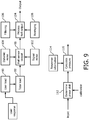
- the Hall-effect dynamic load (phase shift) sensing system ( Figure 9 ) also includes generally the pressure applied by the user. 90 as well a total load 92 which occurs during brushing.
- the total dynamic load creates phase shift between the motor drive signal and the Hall sensor output signal which represents the response of the system.
- the Hall sensor output is shown at 98.
- the sensor output signal is affected by signal noise 100 which can be from various sources including the Hall sensor itself as well as variations in mounting or a change in the resonant system over time. Hall sensor output is also sensitive to dynamic noise 100, which typically is produced by the vibration from a drive train.
- the Hall sensor output is then processed at 104, which can include filtering 106 and averaging 108 to produce a clean output signal. This signal represented as output 104 is subject to further processing.
- the actual phase shift is determined at 112. As indicated above, the phase shift can be determined by a standard zero crossing circuit or by other arrangements. The phase shift is determined for a calibrated appliance.
- the processor uses the phase shift to calculate the dynamic pressure by use of stored information 114 which relates phase shift along one axis to pressure along the other axis. The pressure resulting from the phase shift circuit is shown at 116.
- Peak-to-peak movement of the bristle motion can also be determined by one or the other pressure measurement systems.
- the response curve is a straight line for phase shift against dynamic pressure over at least a range of pressure force of 0-300 grams.
- the results from the displacement (direct force) arrangement will provide a different result than the dynamic force (phase shift) pressure information.
- These two results are then compared against a table which is shown in Figure 10 , to determine the resulting effect relative to a pre-set trigger point, i.e. 300 grams, or other set value.
- the loads produced by the various portions of the mouth are shown in column 120. These include tooth, cheeks/tongue, lips, the combination of tooth and cheeks/tongue, the combination of tooth and lips and the combination of tooth, lips and cheeks/tongue.
- the phase shift measurement is a medium value (column 124), and the peak-to-peak value (column 126) is slightly decreased, there is no change made to the trigger point which is shown in column 130.
- the direct load measurement is negative, the phase shift is low, and the peak-to-peak is a low amount of decrease, there will be no trigger.
- the direct or displacement load measurement When the direct or displacement load measurement is approximately zero, the phase shift is low, and the peak to peak is a low decrease, there will be no trigger.
- the direct load measurement When the direct load measurement is approximately zero, the phase shift is low and the peak to peak indicates a medium decrease, the trigger point is decreased.
- the direct load measurement is positive, the phase shift is medium and the peak to peak indicates a medium decrease, the trigger point pressure remains unchanged.
- the trigger point When the displacement load information is approximately zero, the phase shift is low, and the peak to peak decrease is high, the trigger point will be decreased.
- the particular amounts in each case will depend upon the characteristics of the individual appliance. The result is more accurate information for the user relative to the use of excessive force for the bristles against the teeth and gums.
Landscapes
- Health & Medical Sciences (AREA)
- Dentistry (AREA)
- Epidemiology (AREA)
- Life Sciences & Earth Sciences (AREA)
- Animal Behavior & Ethology (AREA)
- General Health & Medical Sciences (AREA)
- Public Health (AREA)
- Veterinary Medicine (AREA)
- Brushes (AREA)
- Force Measurement Appropriate To Specific Purposes (AREA)
- Measuring Fluid Pressure (AREA)
Description
- This invention relates generally to power toothbrushes with bristle pressure sensors, and more specifically concerns such a toothbrush with improved pressure sensing accuracy.
- Documents in the art are exemplified by
US 2003/000032 A1 andWO 97/00650 A1 - Accordingly, it is desirable to provide a pressure/force sensing system which provides more accurate information to the user concerning the application of excessive force.
- Accordingly, a power toothbrush as claimed is proposed.
-
-
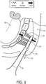
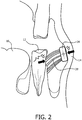
Figure 1 is a plan view of various portions of the mouth of a user and a toothbrush when the exterior (buccal) surfaces of the teeth are being brushed. -
Figure 2 is an elevational view ofFigure 1 . -
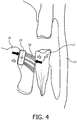
Figure 3 is a plan view of the mouth of a user and a toothbrush when the interior (lingual) surfaces of the teeth are being brushed. -
Figure 4 is a top view of the mouth ofFigure 3 . -
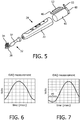
Figure 5 is a simplified diagram of a portion of a toothbrush producing pressure information. -
Figure 6 is an output of a half-cycle o a Hall effect sensor with an output signal calibrated to the drive signal for the appliance. -
Figure 7 is a diagram similar to that ofFigure 6 showing a phase shift in the output signal due to load. -
Figure 8 is a processing diagram producing direct force information from the sensor ofFigure 5 . -
Figure 9 is a processing diagram for determining dynamic force information from the sensor ofFigure 5 . -
Figure 10 is a chart which shows how the information fromFigure 6 and 7 is used to adjust trigger point/threshold values of excessive force applied by the user. - There are several types of loads which are produced by tissues in the mouth during brushing action in addition to pressure on the teeth by toothbrush bristles. There is a spring load which is produced by action of the bristles against the teeth. There is also a damping action, in the form of friction, which occurs between the cheek against the bristle plate supporting the toothbrush bristles, the bristles against the teeth, the tongue against the bristle plate and the lips against the neck of the toothbrush, Still further, there is a load produced by the cheek against the bristle plate, as well as the teeth against the bristles, the lips against the bristle plate, the tongue against the bristle plate, the bristles against the teeth and the teeth against the bristles.
- These various loads are illustrated in
Figures 1 and2 for the exterior (buccal) surfaces of the teeth, whileFigures 3 and4 show the load for the interior (lingual) surfaces. The teeth are illustrated at 12, the cheek is shown at 14, the tongue at 16 and the lips at 18. The toothbrush is shown generally at 20, with a neck portion of the toothbrush shown at 22, a bristle plate portion at 24, and the bristles at 28. Pressure sensor systems, attempting to measure force/load of the bristles against the teeth in order to provide to the user information concerning the application of excessive force relative to possible pressure on it, as well as minimum force for cleansing effectiveness, such sensors, however, actually measure more than just bristle pressure against the teeth and therefore provide somewhat inaccurate information to the user relative to excessive pressure. In particular, due to the inclusion of certain mouth tissue loads in addition to direct bristle pressure against the teeth, the trigger point (threshold) for producing the excessive pressure indication to the user may be too high or too low. If too high, harm may be caused without warning, and if too low, effectiveness can be decreased. - The present invention is designed to provide more accurate and informed trigger point information to the user, in particular more accurate/definitive information concerning the pressure or force applied to the surface of the teeth by the bristles. In the present invention, two different force determination systems are used and the information obtained from each system is used relative to a table to affect the information provided to the user relative to a possible overload or excessive pressure. For example, if a trigger point is set at 300 grams in the processor, the information provided by the two different pressure sensor systems, as well as information concerning peak-to-peak values, is used to adjust the pre-set value at which a warning is provided to the user. One pressure sensing system provides direct force or displacement information, while the other sensing system provides dynamic force information.
- There are several sensing arrangements which provide a direct force or displacement information and arrangements which provide dynamic force information, as well as peak-to-peak information.
- In the present arrangement, the direct force or displacement information is provided by a Hall effect sensor arrangement, while the dynamic load information is provided also by a Hall effect sensor used to measure phase shift between the magnetic field response relative to the phase of the drive signal. Other arrangements can be used, however, to provide the displacement and dynamic load sensing information.
-
Figure 1 shows a simplified view of a power toothbrush arranged to include a Hall effect sensing arrangement to produce both displacement and dynamic load information. The power toothbrush shown generally at 29 includes ahandle 30, abrushhead assembly 32 and a set ofbristles 34, with abristle plate 36 positioned at the distal end of aneck portion 37 of the brushhead assembly. The brushhead assembly is typically removable from the handle portion. The power toothbrush includes a drive train assembly shown very generally at 40 powered by a rechargeable battery. The power toothbrush further includes amicroprocessor 46 which produces the drive signal for the drive train and also processes the signal information from the Hall effect sensor/sensors to provide displacement and dynamic load information. At the rear ofdrive train 40 is amagnet 48. In the embodiment shown, the magnet has the following dimensions: 13.4 mm by 9.0 mm by 4.0 mm. One example of a suitable magnet is neodymium. Other magnets can be used. Mounted within the power toothbrush is a Hall-effect sensor orsensors 52. The Hall-effect sensors 52 can be mounted in various positions within the power toothbrush. In one embodiment, one Hall-effect sensor is mounted on a flex circuit which is attached to the printed circuit board containing the microprocessor, so that the Hall-effect sensor can respond to a changing magnetic field as the toothbrush moves in operation. This results in a dynamic force determination, as explained below. - Another Hall-
effect sensor 53 can be mounted on the drive train frame of the toothbrush located approximately 2.3 mm from the magnet, in approximately the same plane thereof. This Hall-effect sensor recognizes the lateral displacement of the drive train due to force on the bristle field against the teeth, mounted or arranged, such as in a V-spring embodiment, so that the rear end of the drive train moves laterally in response to user force. - In operation, relative to the direct force (displacement) information as the rear end of the drive train and the magnet swing back and forth through a selected angle, the voltage output of Hall-
effect sensor 53 varies sinusoidally. The voltage output of the Hall-effect sensor will vary in accordance to a changing magnetic field. The changing magnet field provides a basis for determining the amount of force applied to the bristles relative to displacement. As force is applied to the bristle field, the rear end of the drive train pivots, including the magnet, producing a lateral displacement of the magnet in the direction of the Hall-effect sensor. The Hall-effect sensor is sensitive enough to detect a change in the magnetic field as the magnet comes closer to the sensor. The microprocessor in the toothbrush includes a table of information in the form of a response curve which relates to the voltage output of the Hall-effect sensor to the displacement of the magnet and hence the force applied to the brush element. The displacement of the magnet will result in a change of voltage output of the Hall-effect sensor relative to the voltage output under no-load conditions. Accordingly, the change in the sensor output is a reliable indication of the displacement force being applied to the bristle field. Reference is made herein toU.S. Provisional Patent Application No. 61/695,396
which concerns a direct-force (displacement) pressure information system for a toothbrush. - With respect to the generation of dynamic load information, a sinusoidal output is also produced by the Hall-effect sensor under no-load conditions. In this arrangement, the Hall-effect sensor detects a change in phase between the drive signal for the appliance and the mechanical response of the brushhead assembly produced by movement of the
magnet 48 as pressure on the bristle field changes. As pressure increases the phase shift increases. Typically, the change in phase will be linear over a defined change of pressure (force), such as from 0 grams to at least 300 grams, at which point the pressure has typically exceeded a maximum value for comfort and effectiveness. Information is also stored in the microprocessor which specifically relates phase shift information and values to force applied, for the particular appliance being tested, so that a specific phase shift is accurately indicative of pressure/force applied to the bristle field of that toothbrush, specifically the dynamic force. - The drive signal is typically a square wave, which in one cycle rises from a zero level to a positive value and after a time determined by the drive frequency declines to a value of opposing polarity, which drive signal cycle continues for the duration of operation of the toothbrush for each event. In the embodiment shown, the drive frequency is 250 Hz, and the amplitude of motion is between 9-11°. This is, however, only one example of operation. The frequency and amplitude may be varied.
- The toothbrush is initially calibrated to determine a time offset which exists between the square wave motor drive signal and the mechanical response signal, as indicated by the signal output from the Hall sensor. This is done under no-load conditions, so that the static phase relationship between the motor drive signal and the response signal is known and can be in effect a zero set for signal processing during actual operation of the toothbrush.
-
Figure 6 shows a single half-cycle of the response signal (Hall sensor output) with the left-hand edge of the signal synchronized to the rising edge of the motor drive signal. As pressure/load is applied to the bristle field, there will be a phase shift in the Hall sensor output signal relative to the motor drive signal. One example of a phase shift (49) is illustrated inFigure 7 . - The value of the phase shift is determined continuously as load is applied to the bristle field. There are many ways to determine phase shift. One is by determining zero crossing. As the phase shifts, the zero crossing of the response signal from the Hall sensor will shift in direct proportion. The zero threshold is determined by averaging the signal over a number of cycles. The time from the start of the motor drive cycle to the first transition of the sensor signal through this zero threshold is then measured. The zero crossing provides an indication of the phase shift.
- Another possibility for obtaining phase shift information is by a quadrature sampling process, in which four samples are used per cycle to extract the DC offset and phase of a sine wave. Four samples are taken 90° apart, in the calculation below by S1, S2, and S4. The average voltage, or the DC offset, can be calculated:


- The above are just two examples of determining phase shift. Other techniques can be used as well.
- Reference is made to Provisional Patent Application No.
61/698,078 -
Figure 8 shows the processing of the direct force (displacement) signal information. The user action is represented atblock 66, indicating the amount of force actually applied by the user. The total load action is represented at 67, which includes loads other than bristle pressure on the teeth. The displacement produced at the rear end of the drive train and the magnet is represented byblock 68. The displacement produces a signal from the Hall-effect sensor as represented byblock 70. The Hall-effect output signal is then processed atblock 74, determining the change in the voltage and output due to the total load. The processing includes averaging the output over a number of cycles, referred to at 76, as well as filtering noise from the signal, including electronic noise and mechanical noise from the motor, which is represented at 78. The result is anoutput signal 80 which is the input signal to the remainder of the processing circuit. As indicated above, the microprocessor includes a response curve or table ofinformation 81 which relates Hall-effect sensor output to a particular displacement force value. The response curve is typically a straight line for an average of 0-300 grams of force. This calculation will include a correlation step represented at 84, which involves correlation of force and Hall sensor values over the force range. Information is provided continuously. - The Hall-effect dynamic load (phase shift) sensing system (
Figure 9 ) also includes generally the pressure applied by the user. 90 as well atotal load 92 which occurs during brushing. The total dynamic load creates phase shift between the motor drive signal and the Hall sensor output signal which represents the response of the system. The Hall sensor output is shown at 98. The sensor output signal is affected bysignal noise 100 which can be from various sources including the Hall sensor itself as well as variations in mounting or a change in the resonant system over time. Hall sensor output is also sensitive todynamic noise 100, which typically is produced by the vibration from a drive train. The Hall sensor output is then processed at 104, which can include filtering 106 and averaging 108 to produce a clean output signal. This signal represented asoutput 104 is subject to further processing. The actual phase shift is determined at 112. As indicated above, the phase shift can be determined by a standard zero crossing circuit or by other arrangements. The phase shift is determined for a calibrated appliance. The processor uses the phase shift to calculate the dynamic pressure by use of storedinformation 114 which relates phase shift along one axis to pressure along the other axis. The pressure resulting from the phase shift circuit is shown at 116. - Peak-to-peak movement of the bristle motion can also be determined by one or the other pressure measurement systems.
- Typically, as indicated above, the response curve is a straight line for phase shift against dynamic pressure over at least a range of pressure force of 0-300 grams. As indicated above, the results from the displacement (direct force) arrangement will provide a different result than the dynamic force (phase shift) pressure information. These two results are then compared against a table which is shown in
Figure 10 , to determine the resulting effect relative to a pre-set trigger point, i.e. 300 grams, or other set value. The loads produced by the various portions of the mouth are shown incolumn 120. These include tooth, cheeks/tongue, lips, the combination of tooth and cheeks/tongue, the combination of tooth and lips and the combination of tooth, lips and cheeks/tongue. When the direct force or displacement load measurement is positive (column 122), the phase shift measurement is a medium value (column 124), and the peak-to-peak value (column 126) is slightly decreased, there is no change made to the trigger point which is shown incolumn 130. When the direct load measurement is negative, the phase shift is low, and the peak-to-peak is a low amount of decrease, there will be no trigger. - When the direct or displacement load measurement is approximately zero, the phase shift is low, and the peak to peak is a low decrease, there will be no trigger. When the direct load measurement is approximately zero, the phase shift is low and the peak to peak indicates a medium decrease, the trigger point is decreased. When the direct load measurement is positive, the phase shift is medium and the peak to peak indicates a medium decrease, the trigger point pressure remains unchanged.
- When the displacement load information is approximately zero, the phase shift is low, and the peak to peak decrease is high, the trigger point will be decreased. The particular amounts in each case will depend upon the characteristics of the individual appliance. The result is more accurate information for the user relative to the use of excessive force for the bristles against the teeth and gums.
Claims (7)
- A power toothbrush (29), comprising:a drive train (40), responsive to a drive signal, for producing a brushing action in bristles of a brushhead assembly coupled to the toothbrush;a magnet (48) at the rear of the drive train (40), the drive train (40) being arranged so that the rear of the drive train (40) moves laterally due to force on the bristles (34);a displacement determining system including a first Hall-effect sensor (53) for determining pressure applied against a user's teeth by the bristles (34) of the toothbrush (29) by a direct force measurement, the first Hall-effect sensor (53) being arranged to recognize lateral displacement of the drive train (40);a phase shift determining system including a second Hall-effect sensor (52) for detecting a change in phase between the drive signal and a mechanical response of the brushhead assembly produced by movement of the magnet as pressure on the bristles changes;a processing system responsive to the pressure determined by the displacement determining system and the change in phase detected by the phase shift determining system for adjusting a trigger point indicative of excessive bristle force.
- The power toothbrush (29) of claim 1, further comprising a microprocessor (46) including a table of information in the form of a response curve which relates a voltage output of the first Hall-effect sensor (53) to the displacement of the magnet (48).
- The power toothbrush (29) of claim 1, wherein information is stored in a microprocessor which relates phase shift information and values to force applied so that a specific phase shift is accurately indicative of force applied to the set of bristles.
- The power toothbrush (29) of claim 1, wherein the phase shift system includes a zero crossing circuit for determining the phase shift.
- The power toothbrush (29) of claim 1, wherein a microprocessor (46) includes the capability of averaging signal output from the second Hall-effect sensor (52) over several cycles and for filtering noise from the signal output of the second Hall-effect sensor (52).
- The power toothbrush (29) of claim 1, comprising a printed circuit board containing a microprocessor (46), wherein said one Hall-effect sensor (52) of the phase shift system is mounted on a flex circuit which is attached to the printed circuit board.
- The power toothbrush (29) of claim 1, wherein the displacement and the phase shift information are provided continuously.
Applications Claiming Priority (2)
| Application Number | Priority Date | Filing Date | Title |
|---|---|---|---|
| US201261746633P | 2012-12-28 | 2012-12-28 | |
| PCT/IB2013/061060 WO2014102667A1 (en) | 2012-12-28 | 2013-12-18 | Pressure sensing electric toothbrush |
Publications (2)
| Publication Number | Publication Date |
|---|---|
| EP2938288A1 EP2938288A1 (en) | 2015-11-04 |
| EP2938288B1 true EP2938288B1 (en) | 2018-11-21 |
Family
ID=50071656
Family Applications (1)
| Application Number | Title | Priority Date | Filing Date |
|---|---|---|---|
| EP13828937.6A Active EP2938288B1 (en) | 2012-12-28 | 2013-12-18 | Pressure sensing electric toothbrush |
Country Status (8)
| Country | Link |
|---|---|
| US (1) | US9259302B2 (en) |
| EP (1) | EP2938288B1 (en) |
| JP (1) | JP6393276B2 (en) |
| CN (1) | CN104883997B (en) |
| BR (1) | BR112015015225A2 (en) |
| RU (1) | RU2657956C2 (en) |
| TR (1) | TR201900933T4 (en) |
| WO (1) | WO2014102667A1 (en) |
Families Citing this family (33)
| Publication number | Priority date | Publication date | Assignee | Title |
|---|---|---|---|---|
| RU2662072C2 (en) | 2013-03-11 | 2018-07-23 | Конинклейке Филипс Н.В. | Electric toothbrush |
| AU2014232399C1 (en) | 2013-03-15 | 2017-11-02 | Water Pik, Inc. | Mechanically driven, sonic toothbrush and water flosser |
| NZ630755A (en) * | 2014-09-10 | 2016-03-31 | Sullivan Clint | A system and method for training use of a toothbrush |
| RU2695257C2 (en) * | 2014-10-07 | 2019-07-22 | Конинклейке Филипс Н.В. | Method for operation of toothbrush with automatic detection of cleaning angle (embodiments) |
| GB2538309B (en) * | 2015-05-15 | 2017-09-20 | Dyson Technology Ltd | Cleaning appliance |
| GB2538300B (en) * | 2015-05-15 | 2017-09-20 | Dyson Technology Ltd | Cleaning appliance |
| CN205568226U (en) | 2015-07-08 | 2016-09-14 | 洁碧有限公司 | Device of brushing teeth |
| JP7100580B2 (en) * | 2015-12-15 | 2022-07-13 | コーニンクレッカ フィリップス エヌ ヴェ | A system and method for deciding when to replace a dental cleaning head and notifying the user |
| US10561480B2 (en) | 2016-05-09 | 2020-02-18 | Water Pik, Inc. | Load sensing for oral devices |
| CN106153105B (en) * | 2016-06-17 | 2018-12-21 | 西安电子科技大学 | A kind of brush dynamics, frequency and the device and method apart from detection |
| US10835028B2 (en) | 2016-11-14 | 2020-11-17 | Colgate-Palmolive Company | Oral care system and method |
| US10582764B2 (en) | 2016-11-14 | 2020-03-10 | Colgate-Palmolive Company | Oral care system and method |
| US11043141B2 (en) | 2016-11-14 | 2021-06-22 | Colgate-Palmolive Company | Oral care system and method |
| US11361672B2 (en) | 2016-11-14 | 2022-06-14 | Colgate-Palmolive Company | Oral care system and method |
| US11213120B2 (en) | 2016-11-14 | 2022-01-04 | Colgate-Palmolive Company | Oral care system and method |
| CN106618776B (en) | 2016-12-02 | 2018-12-14 | 上海携福电器有限公司 | Electric cleaning care appliance, the pressure alarm method and device for the utensil |
| USD844997S1 (en) | 2016-12-15 | 2019-04-09 | Water Pik, Inc. | Toothbrush handle |
| USD845636S1 (en) | 2016-12-15 | 2019-04-16 | Water Pik, Inc. | Toothbrush handle |
| AU2017378474B2 (en) | 2016-12-15 | 2022-06-02 | Water Pik, Inc. | Brushing device with illumination features |
| CN107789085A (en) * | 2017-10-27 | 2018-03-13 | 南京牙小白健康科技有限公司 | A kind of children electric toothbrush for automatically adjusting dynamics and application method |
| CN108652195B (en) * | 2018-07-04 | 2024-02-27 | 同济大学 | Toothbrush with correcting function |
| GB2576114B (en) | 2018-08-02 | 2022-09-07 | Ranir Llc | Pressure sensing system and method for an electric toothbrush |
| US11478068B2 (en) * | 2019-01-15 | 2022-10-25 | Pixart Imaging Inc. | Electric toothbrush adopting force sensing array |
| US11761830B2 (en) | 2019-01-15 | 2023-09-19 | Pixart Imaging Inc. | Earphone with force sensor |
| US10921199B2 (en) | 2019-01-15 | 2021-02-16 | Pixart Imaging Inc. | Force sensor and manufacturing method thereof |
| CN109875708B (en) * | 2019-03-08 | 2021-10-01 | 漯河医学高等专科学校 | Oral cavity cleaning device for oral cavity examination |
| JP2022529601A (en) * | 2019-04-25 | 2022-06-23 | コーニンクレッカ フィリップス エヌ ヴェ | Devices and methods for distinguishing pressure |
| CN112006800A (en) | 2019-05-29 | 2020-12-01 | 上海携福电器有限公司 | Sound wave type electric cleaning and nursing appliance and pressure alarm device for same |
| EP3986328B1 (en) * | 2019-06-21 | 2023-08-09 | Koninklijke Philips N.V. | System for determining a brushing angle of an oral care device |
| USD972302S1 (en) | 2020-03-13 | 2022-12-13 | Ranir, Llc | Toothbrush drive unit |
| CN111870377B (en) * | 2020-08-04 | 2022-03-15 | 上海飞科电器股份有限公司 | Electric tooth brush |
| CN111789692B (en) * | 2020-09-10 | 2020-12-25 | 深圳市力博得科技有限公司 | Control method, device and medium for measuring swing angle and pressure through magnetic variables |
| CN113229976A (en) * | 2021-04-29 | 2021-08-10 | 深圳素士科技股份有限公司 | Electric toothbrush control method and device and electric toothbrush |
Family Cites Families (14)
| Publication number | Priority date | Publication date | Assignee | Title |
|---|---|---|---|---|
| DE3414623C1 (en) * | 1984-04-18 | 1985-10-10 | Blendax-Werke R. Schneider Gmbh & Co, 6500 Mainz | Toothbrush |
| JPH05329024A (en) * | 1992-05-29 | 1993-12-14 | Nippon Philips Kk | Motor driven tooth |
| US5784742A (en) * | 1995-06-23 | 1998-07-28 | Optiva Corporation | Toothbrush with adaptive load sensor |
| US5815872A (en) * | 1997-08-08 | 1998-10-06 | Optiva Corporation | Pressure overload indicator system for power toothbrushes |
| ITBO20010051A1 (en) * | 2001-01-31 | 2002-07-31 | Castellini Spa | DENTAL HANDPIECE, IN PARTICULAR FOR DENTAL UNITS |
| RU2253409C1 (en) * | 2001-03-14 | 2005-06-10 | БРАУН ГмбХ | Method and device for cleaning teeth |
| US6792640B2 (en) * | 2001-06-29 | 2004-09-21 | Homedics, Inc. | Automatic electric toothbrush |
| CN1846651B (en) * | 2005-04-15 | 2011-11-30 | 吴旭榕 | Electric actuator |
| CA2649473C (en) * | 2006-04-20 | 2015-06-30 | Koninklijke Philips Electronics N.V. | System for operating modes for an electric toothbrush |
| WO2008060482A2 (en) * | 2006-11-15 | 2008-05-22 | The Gillette Company | Personal care products and methods |
| US8314377B2 (en) * | 2009-12-23 | 2012-11-20 | Mcneil-Ppc, Inc. | Device and method for detecting plaque in the oral cavity |
| BR112013005086B1 (en) * | 2010-09-20 | 2020-12-15 | The Gillette Company Llc | MANUAL TOOTH BRUSH |
| RU2641159C2 (en) * | 2012-08-31 | 2018-01-16 | Конинклейке Филипс Н.В. | Power sensor providing continuous feedback for toothbrush actuated by resonance using hall sensor |
| CA2883813A1 (en) * | 2012-09-07 | 2014-03-13 | Koninklijke Philips N.V. | Resonantly driven power toothbrush having a pressure-sensing capability using a hall effect sensor |
-
2013
- 2013-12-18 EP EP13828937.6A patent/EP2938288B1/en active Active
- 2013-12-18 WO PCT/IB2013/061060 patent/WO2014102667A1/en active Application Filing
- 2013-12-18 US US14/652,810 patent/US9259302B2/en active Active
- 2013-12-18 CN CN201380068305.XA patent/CN104883997B/en active Active
- 2013-12-18 RU RU2015131132A patent/RU2657956C2/en active
- 2013-12-18 JP JP2015550177A patent/JP6393276B2/en active Active
- 2013-12-18 BR BR112015015225A patent/BR112015015225A2/en not_active IP Right Cessation
- 2013-12-18 TR TR2019/00933T patent/TR201900933T4/en unknown
Non-Patent Citations (1)
| Title |
|---|
| None * |
Also Published As
| Publication number | Publication date |
|---|---|
| CN104883997B (en) | 2017-09-05 |
| JP6393276B2 (en) | 2018-09-19 |
| RU2015131132A (en) | 2017-02-01 |
| WO2014102667A1 (en) | 2014-07-03 |
| US9259302B2 (en) | 2016-02-16 |
| RU2657956C2 (en) | 2018-06-18 |
| TR201900933T4 (en) | 2019-02-21 |
| JP2016505330A (en) | 2016-02-25 |
| EP2938288A1 (en) | 2015-11-04 |
| CN104883997A (en) | 2015-09-02 |
| BR112015015225A2 (en) | 2017-07-11 |
| US20150297327A1 (en) | 2015-10-22 |
Similar Documents
| Publication | Publication Date | Title |
|---|---|---|
| EP2938288B1 (en) | Pressure sensing electric toothbrush | |
| US10441393B2 (en) | Resonantly driven power toothbrush having a pressure-sensing capability using a hall effect sensor | |
| US10524890B2 (en) | Force sensor providing continuous feedback for a resonant drive toothbrush using a hall sensor | |
| RU2662072C2 (en) | Electric toothbrush | |
| US10702206B2 (en) | Toothbrush for oral cavity position detection | |
| US8863343B2 (en) | Oral care apparatus | |
| US8479341B2 (en) | Electric toothbrush | |
| US10980624B2 (en) | Toothbrush with automatic detection of brushing angle |
Legal Events
| Date | Code | Title | Description |
|---|---|---|---|
| PUAI | Public reference made under article 153(3) epc to a published international application that has entered the european phase |
Free format text: ORIGINAL CODE: 0009012 |
|
| 17P | Request for examination filed |
Effective date: 20150728 |
|
| AK | Designated contracting states |
Kind code of ref document: A1 Designated state(s): AL AT BE BG CH CY CZ DE DK EE ES FI FR GB GR HR HU IE IS IT LI LT LU LV MC MK MT NL NO PL PT RO RS SE SI SK SM TR |
|
| AX | Request for extension of the european patent |
Extension state: BA ME |
|
| DAX | Request for extension of the european patent (deleted) | ||
| 17Q | First examination report despatched |
Effective date: 20180322 |
|
| GRAP | Despatch of communication of intention to grant a patent |
Free format text: ORIGINAL CODE: EPIDOSNIGR1 |
|
| RIC1 | Information provided on ipc code assigned before grant |
Ipc: A46B 15/00 20060101ALI20180430BHEP Ipc: A61C 17/22 20060101AFI20180430BHEP |
|
| INTG | Intention to grant announced |
Effective date: 20180606 |
|
| GRAS | Grant fee paid |
Free format text: ORIGINAL CODE: EPIDOSNIGR3 |
|
| GRAA | (expected) grant |
Free format text: ORIGINAL CODE: 0009210 |
|
| AK | Designated contracting states |
Kind code of ref document: B1 Designated state(s): AL AT BE BG CH CY CZ DE DK EE ES FI FR GB GR HR HU IE IS IT LI LT LU LV MC MK MT NL NO PL PT RO RS SE SI SK SM TR |
|
| REG | Reference to a national code |
Ref country code: CH Ref legal event code: EP |
|
| REG | Reference to a national code |
Ref country code: IE Ref legal event code: FG4D |
|
| REG | Reference to a national code |
Ref country code: DE Ref legal event code: R096 Ref document number: 602013047230 Country of ref document: DE |
|
| REG | Reference to a national code |
Ref country code: AT Ref legal event code: REF Ref document number: 1066637 Country of ref document: AT Kind code of ref document: T Effective date: 20181215 |
|
| REG | Reference to a national code |
Ref country code: NL Ref legal event code: FP |
|
| REG | Reference to a national code |
Ref country code: AT Ref legal event code: MK05 Ref document number: 1066637 Country of ref document: AT Kind code of ref document: T Effective date: 20181121 |
|
| PG25 | Lapsed in a contracting state [announced via postgrant information from national office to epo] |
Ref country code: ES Free format text: LAPSE BECAUSE OF FAILURE TO SUBMIT A TRANSLATION OF THE DESCRIPTION OR TO PAY THE FEE WITHIN THE PRESCRIBED TIME-LIMIT Effective date: 20181121 Ref country code: HR Free format text: LAPSE BECAUSE OF FAILURE TO SUBMIT A TRANSLATION OF THE DESCRIPTION OR TO PAY THE FEE WITHIN THE PRESCRIBED TIME-LIMIT Effective date: 20181121 Ref country code: LV Free format text: LAPSE BECAUSE OF FAILURE TO SUBMIT A TRANSLATION OF THE DESCRIPTION OR TO PAY THE FEE WITHIN THE PRESCRIBED TIME-LIMIT Effective date: 20181121 Ref country code: FI Free format text: LAPSE BECAUSE OF FAILURE TO SUBMIT A TRANSLATION OF THE DESCRIPTION OR TO PAY THE FEE WITHIN THE PRESCRIBED TIME-LIMIT Effective date: 20181121 Ref country code: BG Free format text: LAPSE BECAUSE OF FAILURE TO SUBMIT A TRANSLATION OF THE DESCRIPTION OR TO PAY THE FEE WITHIN THE PRESCRIBED TIME-LIMIT Effective date: 20190221 Ref country code: AT Free format text: LAPSE BECAUSE OF FAILURE TO SUBMIT A TRANSLATION OF THE DESCRIPTION OR TO PAY THE FEE WITHIN THE PRESCRIBED TIME-LIMIT Effective date: 20181121 Ref country code: LT Free format text: LAPSE BECAUSE OF FAILURE TO SUBMIT A TRANSLATION OF THE DESCRIPTION OR TO PAY THE FEE WITHIN THE PRESCRIBED TIME-LIMIT Effective date: 20181121 Ref country code: NO Free format text: LAPSE BECAUSE OF FAILURE TO SUBMIT A TRANSLATION OF THE DESCRIPTION OR TO PAY THE FEE WITHIN THE PRESCRIBED TIME-LIMIT Effective date: 20190221 Ref country code: IS Free format text: LAPSE BECAUSE OF FAILURE TO SUBMIT A TRANSLATION OF THE DESCRIPTION OR TO PAY THE FEE WITHIN THE PRESCRIBED TIME-LIMIT Effective date: 20190321 |
|
| PG25 | Lapsed in a contracting state [announced via postgrant information from national office to epo] |
Ref country code: RS Free format text: LAPSE BECAUSE OF FAILURE TO SUBMIT A TRANSLATION OF THE DESCRIPTION OR TO PAY THE FEE WITHIN THE PRESCRIBED TIME-LIMIT Effective date: 20181121 Ref country code: PT Free format text: LAPSE BECAUSE OF FAILURE TO SUBMIT A TRANSLATION OF THE DESCRIPTION OR TO PAY THE FEE WITHIN THE PRESCRIBED TIME-LIMIT Effective date: 20190321 Ref country code: GR Free format text: LAPSE BECAUSE OF FAILURE TO SUBMIT A TRANSLATION OF THE DESCRIPTION OR TO PAY THE FEE WITHIN THE PRESCRIBED TIME-LIMIT Effective date: 20190222 Ref country code: AL Free format text: LAPSE BECAUSE OF FAILURE TO SUBMIT A TRANSLATION OF THE DESCRIPTION OR TO PAY THE FEE WITHIN THE PRESCRIBED TIME-LIMIT Effective date: 20181121 Ref country code: SE Free format text: LAPSE BECAUSE OF FAILURE TO SUBMIT A TRANSLATION OF THE DESCRIPTION OR TO PAY THE FEE WITHIN THE PRESCRIBED TIME-LIMIT Effective date: 20181121 |
|
| PG25 | Lapsed in a contracting state [announced via postgrant information from national office to epo] |
Ref country code: DK Free format text: LAPSE BECAUSE OF FAILURE TO SUBMIT A TRANSLATION OF THE DESCRIPTION OR TO PAY THE FEE WITHIN THE PRESCRIBED TIME-LIMIT Effective date: 20181121 Ref country code: CZ Free format text: LAPSE BECAUSE OF FAILURE TO SUBMIT A TRANSLATION OF THE DESCRIPTION OR TO PAY THE FEE WITHIN THE PRESCRIBED TIME-LIMIT Effective date: 20181121 Ref country code: IT Free format text: LAPSE BECAUSE OF FAILURE TO SUBMIT A TRANSLATION OF THE DESCRIPTION OR TO PAY THE FEE WITHIN THE PRESCRIBED TIME-LIMIT Effective date: 20181121 Ref country code: PL Free format text: LAPSE BECAUSE OF FAILURE TO SUBMIT A TRANSLATION OF THE DESCRIPTION OR TO PAY THE FEE WITHIN THE PRESCRIBED TIME-LIMIT Effective date: 20181121 |
|
| REG | Reference to a national code |
Ref country code: CH Ref legal event code: PL |
|
| REG | Reference to a national code |
Ref country code: DE Ref legal event code: R097 Ref document number: 602013047230 Country of ref document: DE |
|
| PG25 | Lapsed in a contracting state [announced via postgrant information from national office to epo] |
Ref country code: SK Free format text: LAPSE BECAUSE OF FAILURE TO SUBMIT A TRANSLATION OF THE DESCRIPTION OR TO PAY THE FEE WITHIN THE PRESCRIBED TIME-LIMIT Effective date: 20181121 Ref country code: SM Free format text: LAPSE BECAUSE OF FAILURE TO SUBMIT A TRANSLATION OF THE DESCRIPTION OR TO PAY THE FEE WITHIN THE PRESCRIBED TIME-LIMIT Effective date: 20181121 Ref country code: MC Free format text: LAPSE BECAUSE OF FAILURE TO SUBMIT A TRANSLATION OF THE DESCRIPTION OR TO PAY THE FEE WITHIN THE PRESCRIBED TIME-LIMIT Effective date: 20181121 Ref country code: EE Free format text: LAPSE BECAUSE OF FAILURE TO SUBMIT A TRANSLATION OF THE DESCRIPTION OR TO PAY THE FEE WITHIN THE PRESCRIBED TIME-LIMIT Effective date: 20181121 Ref country code: LU Free format text: LAPSE BECAUSE OF NON-PAYMENT OF DUE FEES Effective date: 20181218 Ref country code: RO Free format text: LAPSE BECAUSE OF FAILURE TO SUBMIT A TRANSLATION OF THE DESCRIPTION OR TO PAY THE FEE WITHIN THE PRESCRIBED TIME-LIMIT Effective date: 20181121 |
|
| REG | Reference to a national code |
Ref country code: IE Ref legal event code: MM4A |
|
| PLBE | No opposition filed within time limit |
Free format text: ORIGINAL CODE: 0009261 |
|
| STAA | Information on the status of an ep patent application or granted ep patent |
Free format text: STATUS: NO OPPOSITION FILED WITHIN TIME LIMIT |
|
| REG | Reference to a national code |
Ref country code: BE Ref legal event code: MM Effective date: 20181231 |
|
| 26N | No opposition filed |
Effective date: 20190822 |
|
| PG25 | Lapsed in a contracting state [announced via postgrant information from national office to epo] |
Ref country code: SI Free format text: LAPSE BECAUSE OF FAILURE TO SUBMIT A TRANSLATION OF THE DESCRIPTION OR TO PAY THE FEE WITHIN THE PRESCRIBED TIME-LIMIT Effective date: 20181121 Ref country code: IE Free format text: LAPSE BECAUSE OF NON-PAYMENT OF DUE FEES Effective date: 20181218 |
|
| PG25 | Lapsed in a contracting state [announced via postgrant information from national office to epo] |
Ref country code: BE Free format text: LAPSE BECAUSE OF NON-PAYMENT OF DUE FEES Effective date: 20181231 |
|
| PG25 | Lapsed in a contracting state [announced via postgrant information from national office to epo] |
Ref country code: LI Free format text: LAPSE BECAUSE OF NON-PAYMENT OF DUE FEES Effective date: 20181231 Ref country code: CH Free format text: LAPSE BECAUSE OF NON-PAYMENT OF DUE FEES Effective date: 20181231 |
|
| PG25 | Lapsed in a contracting state [announced via postgrant information from national office to epo] |
Ref country code: MT Free format text: LAPSE BECAUSE OF NON-PAYMENT OF DUE FEES Effective date: 20181218 |
|
| PG25 | Lapsed in a contracting state [announced via postgrant information from national office to epo] |
Ref country code: CY Free format text: LAPSE BECAUSE OF FAILURE TO SUBMIT A TRANSLATION OF THE DESCRIPTION OR TO PAY THE FEE WITHIN THE PRESCRIBED TIME-LIMIT Effective date: 20181121 Ref country code: HU Free format text: LAPSE BECAUSE OF FAILURE TO SUBMIT A TRANSLATION OF THE DESCRIPTION OR TO PAY THE FEE WITHIN THE PRESCRIBED TIME-LIMIT; INVALID AB INITIO Effective date: 20131218 Ref country code: MK Free format text: LAPSE BECAUSE OF NON-PAYMENT OF DUE FEES Effective date: 20181121 |
|
| PGFP | Annual fee paid to national office [announced via postgrant information from national office to epo] |
Ref country code: TR Payment date: 20211207 Year of fee payment: 9 |
|
| PGFP | Annual fee paid to national office [announced via postgrant information from national office to epo] |
Ref country code: NL Payment date: 20211229 Year of fee payment: 9 |
|
| PGFP | Annual fee paid to national office [announced via postgrant information from national office to epo] |
Ref country code: DE Payment date: 20220628 Year of fee payment: 10 |
|
| REG | Reference to a national code |
Ref country code: NL Ref legal event code: MM Effective date: 20230101 |
|
| PG25 | Lapsed in a contracting state [announced via postgrant information from national office to epo] |
Ref country code: NL Free format text: LAPSE BECAUSE OF NON-PAYMENT OF DUE FEES Effective date: 20230101 |
|
| PGFP | Annual fee paid to national office [announced via postgrant information from national office to epo] |
Ref country code: GB Payment date: 20231219 Year of fee payment: 11 |
|
| PGFP | Annual fee paid to national office [announced via postgrant information from national office to epo] |
Ref country code: FR Payment date: 20231226 Year of fee payment: 11 |