EP2937715B1 - Optoelectronic sensor and method for detecting measurement information from a surveillance area - Google Patents
Optoelectronic sensor and method for detecting measurement information from a surveillance area Download PDFInfo
- Publication number
- EP2937715B1 EP2937715B1 EP15159165.8A EP15159165A EP2937715B1 EP 2937715 B1 EP2937715 B1 EP 2937715B1 EP 15159165 A EP15159165 A EP 15159165A EP 2937715 B1 EP2937715 B1 EP 2937715B1
- Authority
- EP
- European Patent Office
- Prior art keywords
- sensor
- angle
- origin
- optical marker
- measurement information
- Prior art date
- Legal status (The legal status is an assumption and is not a legal conclusion. Google has not performed a legal analysis and makes no representation as to the accuracy of the status listed.)
- Active
Links
- 238000005259 measurement Methods 0.000 title claims description 36
- 238000000034 method Methods 0.000 title claims description 9
- 230000005693 optoelectronics Effects 0.000 title claims description 8
- 230000003287 optical effect Effects 0.000 claims description 53
- 239000003550 marker Substances 0.000 claims description 45
- 238000011156 evaluation Methods 0.000 claims description 19
- 238000012544 monitoring process Methods 0.000 claims description 19
- 239000000853 adhesive Substances 0.000 claims description 5
- 230000001070 adhesive effect Effects 0.000 claims description 5
- 230000033001 locomotion Effects 0.000 claims description 5
- 238000001514 detection method Methods 0.000 claims description 4
- 230000001681 protective effect Effects 0.000 description 11
- 230000008901 benefit Effects 0.000 description 3
- 239000003292 glue Substances 0.000 description 3
- 230000005540 biological transmission Effects 0.000 description 2
- 230000005484 gravity Effects 0.000 description 2
- 238000012935 Averaging Methods 0.000 description 1
- 230000004888 barrier function Effects 0.000 description 1
- 230000008859 change Effects 0.000 description 1
- 238000011109 contamination Methods 0.000 description 1
- 238000013461 design Methods 0.000 description 1
- 238000002592 echocardiography Methods 0.000 description 1
- 238000009434 installation Methods 0.000 description 1
- 230000003993 interaction Effects 0.000 description 1
- 238000001208 nuclear magnetic resonance pulse sequence Methods 0.000 description 1
- 230000010363 phase shift Effects 0.000 description 1
- 230000005855 radiation Effects 0.000 description 1
- 230000035945 sensitivity Effects 0.000 description 1
- 239000007787 solid Substances 0.000 description 1
- 230000003068 static effect Effects 0.000 description 1
- 238000012360 testing method Methods 0.000 description 1
- 230000009466 transformation Effects 0.000 description 1
- 238000013024 troubleshooting Methods 0.000 description 1
Images

Classifications
-
- G—PHYSICS
- G01—MEASURING; TESTING
- G01S—RADIO DIRECTION-FINDING; RADIO NAVIGATION; DETERMINING DISTANCE OR VELOCITY BY USE OF RADIO WAVES; LOCATING OR PRESENCE-DETECTING BY USE OF THE REFLECTION OR RERADIATION OF RADIO WAVES; ANALOGOUS ARRANGEMENTS USING OTHER WAVES
- G01S17/00—Systems using the reflection or reradiation of electromagnetic waves other than radio waves, e.g. lidar systems
- G01S17/02—Systems using the reflection of electromagnetic waves other than radio waves
- G01S17/06—Systems determining position data of a target
- G01S17/42—Simultaneous measurement of distance and other co-ordinates
-
- G—PHYSICS
- G01—MEASURING; TESTING
- G01S—RADIO DIRECTION-FINDING; RADIO NAVIGATION; DETERMINING DISTANCE OR VELOCITY BY USE OF RADIO WAVES; LOCATING OR PRESENCE-DETECTING BY USE OF THE REFLECTION OR RERADIATION OF RADIO WAVES; ANALOGOUS ARRANGEMENTS USING OTHER WAVES
- G01S7/00—Details of systems according to groups G01S13/00, G01S15/00, G01S17/00
- G01S7/48—Details of systems according to groups G01S13/00, G01S15/00, G01S17/00 of systems according to group G01S17/00
- G01S7/4808—Evaluating distance, position or velocity data
-
- G—PHYSICS
- G01—MEASURING; TESTING
- G01S—RADIO DIRECTION-FINDING; RADIO NAVIGATION; DETERMINING DISTANCE OR VELOCITY BY USE OF RADIO WAVES; LOCATING OR PRESENCE-DETECTING BY USE OF THE REFLECTION OR RERADIATION OF RADIO WAVES; ANALOGOUS ARRANGEMENTS USING OTHER WAVES
- G01S7/00—Details of systems according to groups G01S13/00, G01S15/00, G01S17/00
- G01S7/48—Details of systems according to groups G01S13/00, G01S15/00, G01S17/00 of systems according to group G01S17/00
- G01S7/481—Constructional features, e.g. arrangements of optical elements
- G01S7/4811—Constructional features, e.g. arrangements of optical elements common to transmitter and receiver
- G01S7/4813—Housing arrangements
-
- G—PHYSICS
- G01—MEASURING; TESTING
- G01S—RADIO DIRECTION-FINDING; RADIO NAVIGATION; DETERMINING DISTANCE OR VELOCITY BY USE OF RADIO WAVES; LOCATING OR PRESENCE-DETECTING BY USE OF THE REFLECTION OR RERADIATION OF RADIO WAVES; ANALOGOUS ARRANGEMENTS USING OTHER WAVES
- G01S7/00—Details of systems according to groups G01S13/00, G01S15/00, G01S17/00
- G01S7/48—Details of systems according to groups G01S13/00, G01S15/00, G01S17/00 of systems according to group G01S17/00
- G01S7/481—Constructional features, e.g. arrangements of optical elements
- G01S7/4817—Constructional features, e.g. arrangements of optical elements relating to scanning
-
- G—PHYSICS
- G01—MEASURING; TESTING
- G01S—RADIO DIRECTION-FINDING; RADIO NAVIGATION; DETERMINING DISTANCE OR VELOCITY BY USE OF RADIO WAVES; LOCATING OR PRESENCE-DETECTING BY USE OF THE REFLECTION OR RERADIATION OF RADIO WAVES; ANALOGOUS ARRANGEMENTS USING OTHER WAVES
- G01S7/00—Details of systems according to groups G01S13/00, G01S15/00, G01S17/00
- G01S7/48—Details of systems according to groups G01S13/00, G01S15/00, G01S17/00 of systems according to group G01S17/00
- G01S7/497—Means for monitoring or calibrating
- G01S7/4972—Alignment of sensor
Definitions
- the invention relates to an optoelectronic sensor and a method for acquiring measurement information from a monitoring area according to the preamble of claim 1 or 11.
- many optoelectronic sensors generate measurement information in more than one dimension.
- the measurement information is thus resolved in a lateral direction, which can be understood as an angular direction.
- laser scanners are particularly suitable.
- a laser scanner a laser beam generated by a laser periodically sweeps over a monitoring area by means of a deflection unit. The light is remitted to objects in the surveillance area and evaluated in the scanner. From the angular position of the deflection unit is closed to the angular position of the object and often also from the light transit time using the speed of light on the distance of the object from the laser scanner.
- a certain angle is used as the reference angle.
- the reference angle is mechanically related to a housing, so for example, the center or a side edge of the windshield, a specific mounting surface or the like.
- the generated measurement data from the field of view of the sensor then have this angle reference and are also correspondingly output at interfaces of the sensor.
- the reference angle specified by the device is rarely suitable in the respective application. For example, a field of interest of interest is only exceptionally limited by chance by the reference angle. The consequence is that the reference coordinate system has to be converted almost always. This entails potential for error and makes systems and applications complicated and costly.
- a laser scanner which monitors at least one protective field.
- the protective field can be rotated along a rotation axis to a mounting surface. This does not solve the mentioned problem.
- the protective field is a defined subsection of the monitoring area and is thus based on the measured data already collected.
- the angle reference does not change.
- the user For each evaluation of measurement data including protective field evaluations, the user must again know and take into account where the device has defined its factory-fixed angular reference.
- the invention has the advantage that the assembly is considerably simplified by the flexible definition of the reference angle or angle origin, since not more attention is paid to a factory-set angle origin and this does not even have to be known.
- a coordinate transformation to a desired angle origin including the required computing power, adjustment of the evaluation and troubleshooting deleted.
- the evaluation unit is preferably configured to determine, as measurement information, distances to a respective detected object from a light transit time.
- the sensor thus becomes a rangefinder and, in the case of an embodiment, a laser scanner to a distance-measuring laser scanner. Not only an angle, but with the distance a complete position of touched object points is detected.
- Other conceivable measurement information that could additionally or alternatively be detected per angular position is intensity or color.
- a zero point of the distance measurement is shifted with the angle origin. The distance zero is thus moved to a position designated by the user, and the evaluation unit then takes into account the corresponding distance offset before the output of measurement data. Negative distances may then also result, meaning that an object closer to the sensor has been detected than the fixed distance zero.
- the optical marker is preferably an adhesive element or a magnet.
- the optical marker is very easily mounted in the surveillance area, especially on the sensor itself and in particular on the windscreen.
- a special adhesive for the residue-free removal after predetermining the angle origin can be used.
- a magnet leaves no residue anyway, but it could be thought of special metallic housing areas that allow its attachment. Incidentally, it is also conceivable not to remove the optical marker at all, but to use, for example, in operation as a reference target.
- the optical marker is preferably punctiform. This is to be understood very broadly and means that a point is designated by the optical marker. Also, two crossed rectangles or a star are here understood as punctiform, as they denote a point like a crosshair. While a strip-shaped marker preferably defines an angle within a 2D plane, the second angle, for example of spherical coordinates, can also be determined by way of a punctiform marker 3D scanner with additional tilting of the scanning plane or a multi-level scanner.
- Fig. 1 shows a schematic sectional view through an optoelectronic sensor in one embodiment as a laser scanner 10.
- a light emitter 12 for example with a laser light source, generates a transmitted light beam 16 with the aid of a transmission optical unit 14.
- the transmitted light beam 16 is emitted by means of a deflection unit 18 into a surveillance area 20 and is remitted there by an optionally present object.
- the remitted light 22 returns to the laser scanner 10 and is detected there via the deflection unit 18 by means of a receiving optical system 24 by a light receiver 26, for example a photodiode or for higher sensitivity of an avalanche photodiode (APD).
- a light receiver 26 for example a photodiode or for higher sensitivity of an avalanche photodiode (APD).
- the light emitter 12 and its transmitting optics 14 are located in a central opening of the receiving optics 24. This is only an exemplary possibility of the arrangement.
- the invention also includes alternative solutions, such as with its own mirror range for the transmitted light beam 16 or with divider mirrors.
- the deflection unit 18 is set in a continuous rotational movement by a motor 28 so that the transmitted light beam 16 scans a plane as a monitoring area 20.
- an angle measuring unit 30 is arranged in order to detect the respective angular position of the deflection unit 18.
- the angle measuring unit 30 is formed here by way of example of a slit disk as a WinkelrichverAvemung and a forked light barrier as a sample.
- An evaluation unit 32 is connected to the light emitter 12, the light receiver 26, the motor 28 and the angle measuring unit 30.
- the evaluation unit 32 evaluates the received signal of the light receiver 26.
- the light transit time between emission of the transmitted light beam 16 and reception of remitted light 22 is measured in order to close the distance of a touched object from the laser scanner 10 using the speed of light.
- phase-based methods are known in which the continuous transmitted light is modulated and the phase shift of the received light compared to the transmitted light is evaluated.
- the respective angular position, below which the transmitted light beam 16 was emitted, is known to the evaluation unit of the angle measuring unit 30.
- two-dimensional polar coordinates of all object points in the surveillance area 20 are available after each scan period over the angle and the distance.
- the object positions or object contours are known and can be transmitted via an interface 34 or displayed on the laser scanner 10.
- the interface 34 also serves as parameterization interface, via which the evaluation unit 32 data can be recorded.
- a separate parameterization interface can be provided.
- the interface 34 can be designed to be safe, in particular a safe output (OSSD, Output Signal Switching Device) for a safety-related shutdown signal upon detection of a protective field violation.
- OSSD Output Signal Switching Device
- the laser scanner 10 is accommodated in a housing 36, which has a circumferential windshield 38.
- extensions of the laser scanner 10 are to be mentioned, with which more than one level can be monitored.
- the deflection unit 18 can be tilted in addition to the to vary the second solid angle.
- Another example is laser scanners with a plurality of scanning planes, for example, by rotation of a plurality of transmitters and receivers arranged one above the other or a camera line, in particular a distance-measuring camera, whereby a three-dimensional spatial area can likewise be scanned.
- 3D scanners not only the angle in the direction of rotation, but also the tilt angle or the vertical position is preferably detected.
- FIG. 2 shows a plan view of another embodiment of a laser scanner 10 with its monitoring area 20.
- the illustrated assembly and controls of the laser scanner 10 are of no relevance to the understanding of the invention.
- This laser scanner 10 has an opening angle of 190 °.
- the device-side angle origin 40 is here perpendicular to a mounting surface 42.
- FIG. 3 shows a plan view of yet another embodiment of a laser scanner 10 with its monitoring area 20, now with an opening angle of 270 °. Again, the device-side angle origin 40 is perpendicular to a mounting surface 42.
- the device-side angle origin 40 can be set arbitrarily in principle, but does not fit regularly in the respective application to a direction that would like to mark the user as an angle origin.
- the evaluation unit 32 is capable of arbitrarily restoring the angle origin, which is used as a reference angle for output measurement data, within the opening angle. Internally, this is processed, for example, as an angular offset of the desired angle origin relative to the device-side angle origin 40.
- the desired angle origin can be entered in general in any way, such as parameters via the interface 34 or by means of a rotary ring, for example, has a notch or other mark for the desired angle origin, which is then rotated as the application the desired Angle origin would like to lay.
- This type of specification of a desired angular origin 44 is particularly advantageous if the laser scanner 10 ideally has a large opening angle of 360 °. Then the user can adjust the mounting position and mounting orientation completely free of an angle origin to his circumstances and only then set the desired angle origin 44 and thus the angular orientation after installation by applying the optical marker 46.
- FIG. 5 shows again a schematic three-dimensional external view of a laser scanner 10, which differs from that of the FIG. 4 can capture a three-dimensional monitoring area 20.
- the deflection unit 18 additionally tiltable or provided a multi-level scan.
- the vertical angle is either the tilt angle which forms the third sphere coordinate or the angle corresponding to a distance of the multiple planes.
- the zero point or angle origin can be set not only horizontally within the plane but also vertically in a direction perpendicular thereto.
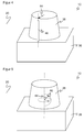
- a punctiform optical marker 46 analogous to the embodiment according to FIG. 4 may be formed as a glue point for sticking to the windshield 38.
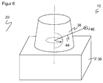
- FIG. 6 shows a comparison variant of the embodiment according to FIG. 5 , which differs in that the optical marker 46 is not attached directly to the laser scanner 10, but is free in space within the monitoring area 20.
- the angle of origin can be defined via the optical marker 46.
- the optical marker 46 designates not only an angle origin, but overall the origin for all three spherical coordinates of the spatial coordinate system of the measurement data of the laser scanner 10, which of course can be converted into more usual Cartesian coordinates prior to output to the user.
- an axis can be placed on the beam of laser scanner 10 to optical marker 46, so a tilted coordinate system can be selected.
- the attachment of the optical marker 46 free in the room along with redefinition of the distance zero point is also in the two-dimensional case, for example according to FIG. 4 conceivable.
Description
Die Erfindung betrifft einen optoelektronischen Sensor und ein Verfahren zur Erfassung von Messinformationen aus einem Überwachungsbereich nach dem Oberbegriff von Anspruch 1 beziehungsweise 11.The invention relates to an optoelectronic sensor and a method for acquiring measurement information from a monitoring area according to the preamble of claim 1 or 11.
Viele optoelektronische Sensoren erzeugen, anders als beispielsweise eine einfache Lichtschranke, Messinformation in mehr als einer Dimension. Die Messinformationen sind also in einer lateralen Richtung aufgelöst, die sich als Winkelrichtung auffassen lässt. Als Messsystem mit großem horizontalem Winkelbereich eignen sich Laserscanner besonders. In einem Laserscanner überstreicht ein von einem Laser erzeugter Lichtstrahl mit Hilfe einer Ablenkeinheit periodisch einen Überwachungsbereich. Das Licht wird an Objekten in dem Überwachungsbereich remittiert und in dem Scanner ausgewertet. Aus der Winkelstellung der Ablenkeinheit wird auf die Winkelposition des Objektes und häufig zudem aus der Lichtlaufzeit unter Verwendung der Lichtgeschwindigkeit auf die Entfernung des Objektes von dem Laserscanner geschlossen.Unlike optoelectronic sensors, for example, many optoelectronic sensors generate measurement information in more than one dimension. The measurement information is thus resolved in a lateral direction, which can be understood as an angular direction. As a measuring system with a large horizontal angle range, laser scanners are particularly suitable. In a laser scanner, a laser beam generated by a laser periodically sweeps over a monitoring area by means of a deflection unit. The light is remitted to objects in the surveillance area and evaluated in the scanner. From the angular position of the deflection unit is closed to the angular position of the object and often also from the light transit time using the speed of light on the distance of the object from the laser scanner.
Mit den Winkel- und Entfernungsangaben ist der Ort eines Objektes in dem Überwachungsbereich in zweidimensionalen Polarkoordinaten erfasst. Damit lassen sich die Positionen von Objekten ermitteln oder deren Kontur bestimmen. Die dritte Raumkoordinate kann durch eine Relativbewegung in Querrichtung ebenfalls erfasst werden, beispielsweise durch einen weiteren Bewegungsfreiheitsgrad der Ablenkeinheit in dem Laserscanner oder indem das Objekt relativ zu dem Laserscanner befördert wird. So können auch dreidimensionale Konturen ausgemessen werden.The angle and distance indications capture the location of an object in the monitoring area in two-dimensional polar coordinates. This allows the positions of objects to be determined or their contour to be determined. The third spatial coordinate can also be detected by a relative movement in the transverse direction, for example by a further degree of freedom of movement of the deflection unit in the laser scanner or by the object being conveyed relative to the laser scanner. Thus, even three-dimensional contours can be measured.
Neben solchen Messanwendungen werden Laserscanner auch in der Sicherheitstechnik zur Überwachung einer Gefahrenquelle eingesetzt, wie sie beispielsweise eine gefährliche Maschine darstellt. Ein derartiger Sicherheitslaserscanner ist aus der
In der Sicherheitstechnik eingesetzte Sensoren müssen besonders zuverlässig arbeiten und deshalb hohe Sicherheitsanforderungen erfüllen, beispielsweise die Norm EN13849 für Maschinensicherheit und die Gerätenorm EN61496 für berührungslos wirkende Schutzeinrichtungen (BWS). Zur Erfüllung dieser Sicherheitsnormen sind eine Reihe von Maßnahmen zu treffen, wie sichere elektronische Auswertung durch redundante, diversitäre Elektronik, Funktionsüberwachung oder speziell Überwachung der Verschmutzung optischer Bauteile, insbesondere einer Frontscheibe, und/oder Vorsehen von einzelnen Testzielen mit definierten Reflexionsgraden, die unter den entsprechenden Scanwinkeln erkannt werden müssen.Sensors used in safety technology must work extremely reliably and therefore meet high safety requirements, for example the EN13849 standard for machine safety and the EN61496 device standard for non-contact protective devices (ESPE). To meet these safety standards, a number of measures must be taken, such as secure electronic evaluation by redundant, diverse electronics, function monitoring or specially monitoring the contamination of optical components, in particular a windscreen, and / or providing individual test objectives with defined degrees of reflection, among the corresponding Scan angles must be detected.
Nun ergeben sich bei derartigen Messungen sehr häufig Probleme daraus, dass eine Winkelausrichtung vorgegeben ist. Es wird nämlich ein bestimmter Winkel als Bezugswinkel verwendet. Dies definiert beispielsweise, wo für den Sensor "vorne" ist, oder präziser ausgedrückt, auf welchen Winkelursprung sich die winkelaufgelösten Messdaten beziehen. Üblicherweise wird der Bezugswinkel mechanisch auf ein Gehäuse bezogen, also beispielsweise die Mitte oder eine Seitenkante der Frontscheibe, eine bestimmte Montagefläche oder dergleichen. Die generierten Messdaten aus dem Sichtbereich des Sensors haben dann diesen Winkelbezug und werden auch entsprechend an Schnittstellen des Sensors ausgegeben. Der von dem Gerät vorgegebene Bezugswinkel ist aber in der jeweiligen Anwendung selten passend. So wird beispielsweise ein interessierender Sichtbereich nur ausnahmsweise gerade zufällig durch den Bezugswinkel begrenzt. Die Folge ist, dass das Bezugskoordinatensystem praktisch immer umgerechnet werden muss. Das birgt Fehlerpotential und macht Systeme und Anwendungen kompliziert und kostenaufwändig.Now arise in such measurements very often problems that an angular orientation is predetermined. Namely, a certain angle is used as the reference angle. This defines, for example, where the sensor is "forward", or more precisely, to which angle origin the angle-resolved measurement data relate. Usually, the reference angle is mechanically related to a housing, so for example, the center or a side edge of the windshield, a specific mounting surface or the like. The generated measurement data from the field of view of the sensor then have this angle reference and are also correspondingly output at interfaces of the sensor. However, the reference angle specified by the device is rarely suitable in the respective application. For example, a field of interest of interest is only exceptionally limited by chance by the reference angle. The consequence is that the reference coordinate system has to be converted almost always. This entails potential for error and makes systems and applications complicated and costly.
Aus der
Die
Es ist daher Aufgabe der Erfindung, den Umgang mit den Messdaten des Laserscanners zu vereinfachen.It is therefore an object of the invention to simplify the handling of the measurement data of the laser scanner.
Diese Aufgabe wird durch einen optoelektronischen Sensor und ein Verfahren zur Erfassung von Messinformationen aus einem Überwachungsbereich nach Anspruch 1 beziehungsweise 11 gelöst. Dabei geht die Erfindung von dem Grundgedanken aus, den Winkelursprung oder Bezugswinkel des Sensors einstellbar zu machen. Typischerweise wird dadurch festgelegt, wo in dem Überwachungsbereich die Winkelposition 0° liegt, aber eine abweichende Übereinkunft des Winkelursprungs bei jeder anderen Winkelposition ist ebenso möglich. Die Winkelauflösung bezüglich des Winkelursprungs kann in den Messdaten explizit oder implizit angegeben werden. Eine explizite Angabe wäre beispielsweise die Ausgabe von Tupeln der Art (Winkelposition, Messwert). Bei einer impliziten Angabe bezieht sich eine Messwertreihe durch eine bekannte oder irgendwie gekennzeichnete Position innerhalb der Messreihe, häufig deren ersten Messwert, implizit auf den Winkelursprung. Der Messwert an dieser Position gehört damit zu dem Winkelursprung. Die übrigen Messwerte tragen ihre Winkelauflösung implizit durch ihre Position innerhalb der Messreihe, etwa indem die Messreihe in äquidistanten oder anderen Winkelschritten aufgenommen wird.This object is achieved by an optoelectronic sensor and a method for acquiring measurement information from a surveillance area according to claim 1 or 11. The invention is based on the basic idea of making the angle origin or reference angle of the sensor adjustable. Typically this determines where in the surveillance area the angular position is 0 °, but a different agreement of the angular origin at any other angular position is also possible. The angular resolution with respect to the angle origin can be specified explicitly or implicitly in the measurement data. An explicit specification would be, for example, the output of tuples of the type (angular position, measured value). In the case of an implicit statement, a series of measurements implicitly refers to the angle origin through a known or somehow identified position within the measurement series, often its first measurement value. The measured value at this position thus belongs to the angle origin. The other measured values implicitly carry their angular resolution by their position within the measurement series, for example by taking the measurement series in equidistant or other angular steps.
Die Erfindung hat den Vorteil, dass durch die flexible Festlegung des Bezugswinkels beziehungsweise Winkelursprungs die Montage erheblich vereinfacht wird, da nicht mehr auf einen werkseitig eingestellten Winkelursprung geachtet werden und dieser nicht einmal mehr bekannt sein muss. Außerdem entfällt eine Koordinatentransformation auf einen gewünschten Winkelursprung einschließlich der dazu erforderlichen Rechenleistung, Anpassung der Auswertung und Fehlersuche.The invention has the advantage that the assembly is considerably simplified by the flexible definition of the reference angle or angle origin, since not more attention is paid to a factory-set angle origin and this does not even have to be known. In addition, a coordinate transformation to a desired angle origin including the required computing power, adjustment of the evaluation and troubleshooting deleted.
Der Sensor ist vorzugsweise ein Laserscanner, der einen Lichtsender zum Aussenden eines Abtaststrahls und eine Ablenkeinheit zum periodischen Ablenken des Abtaststrahls aufweist, um durch die Ablenkbewegung den Überwachungsbereich abzutasten und dabei die winkelaufgelösten Messinformationen zu gewinnen. Hier wird also mit Hilfe einer Ablenkeinheit, wie eines Schwing- oder Drehspiegels, eines Polygonrades oder eines insgesamt drehbaren Messkopfes ein Winkelbereich sukzessive und wiederholt abgetastet. Dabei entsteht eine Überwachungsebene, die durch zusätzliches Verkippen der Ablenkeinheit in Querrichtung zu einem dreidimensionalen Raumbereich erweitert werden kann.The sensor is preferably a laser scanner having a light emitter for emitting a scanning beam and a deflecting unit for periodically deflecting the scanning beam to scan the surveillance area by the deflecting motion to thereby obtain the angle resolved measurement information. In this case, an angular range is thus scanned successively and repeatedly with the aid of a deflection unit, such as a swinging or rotating mirror, a polygonal wheel or an altogether rotatable measuring head. This creates a monitoring level that can be extended by additional tilting of the deflection in the transverse direction to a three-dimensional space area.
Die Auswertungseinheit ist bevorzugt dafür ausgebildet, als Messinformationen Entfernungen zu einem jeweils erfassten Objekt aus einer Lichtlaufzeit zu bestimmen. Der Sensor wird damit zu einem Entfernungsmesser und im Falle einer Ausführungsform als Laserscanner zu einem entfernungsmessenden Laserscanner. Dabei wird nicht nur ein Winkel, sondern mit dem Abstand eine vollständige Position von angetasteten Objektpunkten erfasst. Andere denkbare Messinformationen, die zusätzlich oder alternativ je Winkelposition erfasst werden könnten, sind Intensität oder Farbe. Vorzugsweise wird mit dem Winkelursprung auch ein Nullpunkt der Entfernungsmessung verschoben. Die Entfernung Null wird damit an eine von dem Benutzer bezeichnete Position verlegt, und die Auswertungseinheit berücksichtigt dann vor der Ausgabe von Messdaten den entsprechenden Entfernungsoffset. Es können sich dann auch negative Entfernungen ergeben, die bedeuten, dass ein Objekt näher am Sensor erfasst wurde als die festgelegte Entfernung Null.The evaluation unit is preferably configured to determine, as measurement information, distances to a respective detected object from a light transit time. The sensor thus becomes a rangefinder and, in the case of an embodiment, a laser scanner to a distance-measuring laser scanner. Not only an angle, but with the distance a complete position of touched object points is detected. Other conceivable measurement information that could additionally or alternatively be detected per angular position is intensity or color. Preferably, a zero point of the distance measurement is shifted with the angle origin. The distance zero is thus moved to a position designated by the user, and the evaluation unit then takes into account the corresponding distance offset before the output of measurement data. Negative distances may then also result, meaning that an object closer to the sensor has been detected than the fixed distance zero.
Die Auswertungseinheit ist dafür ausgebildet, einen optischen Marker zu erkennen, welcher die durch den Benutzer bezeichnete Winkelposition festlegt. Der Sensor kann auf diese Weise selbsttätig eine durch den Benutzer festlegbare Winkelposition erfassen. Daher sind keine besonderen Hilfsmittel zur Parametrierung des Winkelursprungs, wie ein PC oder dergleichen, und keine Schnittstellen des Sensors erforderlich. Optischer Marker, etwa als Aufkleber, sind zudem ausgesprochen preisgünstig.The evaluation unit is designed to recognize an optical marker which defines the angular position designated by the user. In this way, the sensor can automatically detect an angular position that can be determined by the user. Therefore, no special tools for parameterizing the angle origin, such as a PC or the like, and no interfaces of the sensor are required. Optical markers, such as stickers, are also very reasonably priced.
Die Auswertungseinheit ist bevorzugt dafür ausgebildet, die Erkennung des optischen Markers als Auslöser für eine neue Festlegung des Winkelursprungs aufzufassen. Schon das Anbringen eines optischen Markers löst dann einen neuen Winkelbezug aus. Der optische Marker kann dafür auch eine besondere Codierung tragen, wie einen Barcode, oder spezielle optische Eigenschaften durch Form, Farbe oder Muster aufweisen, die ihn als optischen Marker zum Festlegen des Winkelursprungs identifiziert. Alternativ zu einer automatischen Erkennung des optischen Markers ist auch ein Bedienelement denkbar, das eine Suche des Sensors nach optischen Markern auslöst.The evaluation unit is preferably designed to interpret the recognition of the optical marker as a trigger for a new determination of the angle origin. Even attaching an optical marker then triggers a new angle reference. The optical marker can also carry a special coding, such as a Barcode, or have special optical properties by shape, color or pattern that identifies him as an optical marker for setting the angle origin. As an alternative to an automatic detection of the optical marker, a control element is also conceivable which triggers a search of the sensor for optical markers.
Der optische Marker ist an einer Frontscheibe des Sensors angeordnet. Das erleichtert dem Benutzer in einem relevanten Umfeld zu erkennen, wo der neue Winkelursprung liegen wird. Umgekehrt hat der Sensor eine klare Vorstellung, wo optische Marker zu suchen sind. Gerade bei entfernungsmessenden Sensoren sind optische Marker auf der Frontscheibe anhand des Abstands leicht zu finden und zu identifizieren.The optical marker is arranged on a front pane of the sensor. This makes it easier for the user to identify in a relevant environment where the new angle origin will be. Conversely, the sensor has a clear idea of where to look for optical markers. Especially with distance-measuring sensors, optical markers on the windshield are easy to find and identify on the basis of the distance.
Der optische Marker ist bevorzugt ein Klebeelement oder ein Magnet. So wird der optische Marker sehr einfach im Überwachungsbereich angebracht, speziell auch an dem Sensor selbst und insbesondere an dessen Frontscheibe. Im letztgenannten Fall kann ein spezieller Kleber für die rückstandslose Entfernung nach Vorgeben des Winkelursprungs verwendet werden. Ein Magnet hinterlässt ohnehin keine Rückstände, aber es könnte an spezielle metallische Gehäusebereiche gedacht werden, die dessen Anbringung ermöglichen. Im Übrigen ist auch denkbar, den optischen Marker gar nicht zu entfernen, sondern beispielsweise im Betrieb als Referenzziel zu verwenden.The optical marker is preferably an adhesive element or a magnet. Thus, the optical marker is very easily mounted in the surveillance area, especially on the sensor itself and in particular on the windscreen. In the latter case, a special adhesive for the residue-free removal after predetermining the angle origin can be used. A magnet leaves no residue anyway, but it could be thought of special metallic housing areas that allow its attachment. Incidentally, it is also conceivable not to remove the optical marker at all, but to use, for example, in operation as a reference target.
Der optische Marker ist bevorzugt streifenförmig. Seine Geometrie besitzt also eine klare Vorzugsrichtung größter Ausdehnung, wie im Falle eines länglichen Rechtecks. Der optische Marker wird dann vorteilhafterweise mit dieser Vorzugsrichtung senkrecht zu der Winkelrichtung angebracht, im Falle eines Laserscanners also senkrecht zu dessen Überwachungsebene. So kann der optische Marker insgesamt ausreichend groß für eine zuverlässige Erfassung, jedoch in Winkelrichtung ausreichend scharf aufgelöst sein.The optical marker is preferably strip-shaped. Its geometry thus has a clear preferential direction of greatest extent, as in the case of an oblong rectangle. The optical marker is then advantageously mounted with this preferred direction perpendicular to the angular direction, in the case of a laser scanner so perpendicular to its monitoring plane. Thus, the optical marker overall can be sufficiently large for reliable detection, but sufficiently sharply resolved in the angular direction.
Der optische Marker ist bevorzugt punktförmig. Das ist hier sehr breit zu verstehen und bedeutet, dass durch den optischen Marker ein Punkt bezeichnet wird. Auch zwei gekreuzte Rechtecke oder ein Stern werden hier also als punktförmig aufgefasst, da sie wie ein Fadenkreuz einen Punkt bezeichnen. Während ein streifenförmiger Marker vorzugsweise einen Winkel innerhalb einer 2D-Ebene festlegt, kann über einen punktförmigen Marker auch der zweite Winkel beispielsweise von Kugelkoordinaten eines 3D-Scanners mit zusätzlicher Verkippung der Abtastebene oder eines Mehrebenenscanners festgelegt werden.The optical marker is preferably punctiform. This is to be understood very broadly and means that a point is designated by the optical marker. Also, two crossed rectangles or a star are here understood as punctiform, as they denote a point like a crosshair. While a strip-shaped marker preferably defines an angle within a 2D plane, the second angle, for example of spherical coordinates, can also be determined by way of a punctiform marker 3D scanner with additional tilting of the scanning plane or a multi-level scanner.
Die Auswertungseinheit legt bevorzugt den Winkelursprung gegenüber der bezeichneten Winkelposition mit einem Versatz fest. Ohne Versatz liegt der neue Winkelursprung gerade an der Winkelposition, die der Benutzer bezeichnet hat, beispielsweise dort, wo der optische Marker angebracht ist. Wegen der endlichen Ausdehnung des optischen Markers wird beispielsweise dessen Schwerpunkt in Winkelrichtung verwendet. Durch einen Versatz kann der Winkelursprung stattdessen beispielsweise dorthin gelegt werden, wo der optische Marker die Sicht nicht mehr beschränkt, also an dessen rechte oder linke Kante. Ein Versatz ermöglicht auch andere Abweichungen, etwa dass die durch den Benutzer bezeichnete Position nicht 0°, sondern 90° oder irgendeinen anderen Wert festlegen soll.The evaluation unit preferably determines the angle origin with respect to the designated angular position with an offset. Without offset, the new angle origin lies just at the angular position designated by the user, for example where the optical marker is located. Because of the finite extent of the optical marker, for example, its center of gravity in the angular direction is used. By an offset, the angle origin can instead be placed, for example, where the optical marker no longer limits the view, ie at its right or left edge. An offset also allows other deviations, such as that the position designated by the user should not specify 0 ° but 90 ° or any other value.
Der Sensor erfasst vorzugsweise Messinformationen aus einem Winkelbereich von zumindest 270°, insbesondere von 360°. Ein derart großer Winkelbereich ist beispielsweise mit einem Laserscanner erreichbar. Vor allem bei einem Rund-Um-Sensor mit 360°, aber mit kleinen Einschränkungen auch bei etwas kleinerem Winkelbereich, legt das Gerät eigentlich weder durch seine Geometrie noch diejenige des Überwachungsbereichs noch einen Winkelursprung fest, dieser wird reine Konvention und eigentlich ausschließlich noch durch einen Blick in das Handbuch erkennbar. Aufgrund der Erfindung wird es nun möglich, den Sensor ohne jede Rücksicht auf einen Winkelursprung zu montieren. Erst anschließend wird dann irgendwo rund um den Sensor eine für die Anwendung bequem passende Richtung festgelegt, die der Sensor als "vorne" ansehen soll, also als Winkelursprung.The sensor preferably detects measurement information from an angular range of at least 270 °, in particular 360 °. Such a large angular range can be achieved, for example, with a laser scanner. Especially with a round-Um-sensor with 360 °, but with small restrictions even with a smaller angle range, the device actually sets neither by its geometry nor that of the surveillance area nor an angle origin, this is pure convention and actually only by a Look into the manual recognizable. Due to the invention, it is now possible to mount the sensor without any consideration for an angular origin. Only then, somewhere around the sensor, is a convenient direction for the application determined, which the sensor should regard as "front", ie as an angle origin.
Das erfindungsgemäße Verfahren kann auf ähnliche Weise durch weitere Merkmale ausgestaltet werden und zeigt dabei ähnliche Vorteile. Derartige weitere Merkmale sind beispielhaft, aber nicht abschließend, in den sich an die unabhängigen Ansprüche anschließenden Unteransprüchen beschrieben.The inventive method can be configured in a similar manner by further features and shows similar advantages. Such further features are exemplary, but not exhaustive, in which subclaims following the independent claims are described.
Die Erfindung wird nachstehend auch hinsichtlich weiterer Vorteile und Merkmale unter Bezugnahme auf die beigefügte Zeichnung anhand von Ausführungsbeispielen erläutert. Die Figuren der Zeichnung zeigen in:
- Fig. 1
- eine schematische Schnittdarstellung durch einen Laserscanner;
- Fig. 2
- eine Draufsicht auf eine Ausführungsform eines Laserscanners und dessen Überwachungsbereich bei einem Öffnungswinkel von 190°;
- Fig. 3
- eine Draufsicht auf eine Ausführungsform eines Laserscanners und dessen Überwachungsbereich bei einem
Öffnungswinkel von 270°; und - Fig. 4
- eine schematische dreidimensionale Ansicht eines Laserscanners zur Veranschaulichung der Festlegung des Winkelursprungs mit einem Klebestreifen;
- Fig. 5
- eine schematische dreidimensionale Ansicht eines Laserscanners mit dreidimensionalem Überwachungsbereich zur Veranschaulichung der Festlegung des Winkelursprungs mit einem Klebepunkt; und
- Fig. 6
- eine schematische dreidimensionale Ansicht eines Laserscanners ähnlich
Figur 5 , wobei hier statt eines Klebepunkts ein frei bewegliches Referenzziel verwendet wird.
- Fig. 1
- a schematic sectional view through a laser scanner;
- Fig. 2
- a plan view of an embodiment of a laser scanner and its surveillance area at an opening angle of 190 °;
- Fig. 3
- a plan view of an embodiment of a laser scanner and its surveillance area at an opening angle of 270 °; and
- Fig. 4
- a schematic three-dimensional view of a laser scanner to illustrate the determination of the angle origin with an adhesive strip;
- Fig. 5
- a schematic three-dimensional view of a laser scanner with three-dimensional monitoring area to illustrate the determination of the angle origin with a glue point; and
- Fig. 6
- a schematic three-dimensional view of a laser scanner similar
FIG. 5 , where here, instead of a glue point, a freely movable reference target is used.
Die Ablenkeinheit 18 wird von einem Motor 28 in eine kontinuierliche Drehbewegung versetzt, so dass der Sendelichtstrahl 16 eine Ebene als Überwachungsbereich 20 abtastet. Am Außenumfang der Ablenkeinheit 18 ist eine Winkelmesseinheit 30 angeordnet, um die jeweilige Winkelstellung der Ablenkeinheit 18 zu erfassen. Die Winkelmesseinheit 30 wird hier beispielhaft von einer Strichscheibe als Winkelmaßverkörperung und einer Gabellichtschranke als Abtastung gebildet.The
Eine Auswertungseinheit 32 ist mit dem Lichtsender 12, dem Lichtempfänger 26, dem Motor 28 und der Winkelmesseinheit 30 verbunden. Die Auswertungseinheit 32 wertet das Empfangssignal des Lichtempfängers 26 aus. In einer Ausführungsform als entfernungsmessender Laserscanner wird dabei die Lichtlaufzeit zwischen Aussenden des Sendelichtstrahls 16 und Empfang von remittiertem Licht 22 gemessen, um unter Verwendung der Lichtgeschwindigkeit auf den Abstand eines angetasteten Objektes von dem Laserscanner 10 zu schließen. Für das Messen von Lichtlaufzeiten sind phasenbasierte Verfahren bekannt, bei denen das kontinuierliche Sendelicht moduliert und die Phasenverschiebung des empfangenen gegenüber dem gesendeten Licht ausgewertet wird. Bei pulsbasierten Verfahren oder Pulslaufzeitverfahren arbeitet der Lichtsender 12 in einem Einzelpulsbetrieb mit verhältnismäßig hohen Pulsenergien, und der Laserscanner 10 misst Objektabstände anhand der Laufzeit zwischen dem Aussenden und Empfangen eines Einzellichtpulses. Denkbar ist auch, dass anstelle von Einzelpulsen Pulsfolgen ausgesandt und die entsprechenden Pulsechos ausgewertet werden, beispielsweise in einer Pseudozufallscodierung oder einem Pulsmittelungsverfahren.An
Die jeweilige Winkelstellung, unter welcher dabei der Sendelichtstrahl 16 ausgesandt wurde, ist der Auswertungseinheit von der Winkelmesseinheit 30 bekannt. Somit stehen nach jeder Scanperiode über den Winkel und die Entfernung zweidimensionale Polarkoordinaten aller Objektpunkte in dem Überwachungsbereich 20 zur Verfügung. Damit sind die Objektpositionen beziehungsweise Objektkonturen bekannt und können über eine Schnittstelle 34 übertragen oder am Laserscanner 10 angezeigt werden. Die Schnittstelle 34 dient umgekehrt auch als Parametrierschnittstelle, über welche der Auswertungseinheit 32 Daten eingespielt werden können. Alternativ kann eine eigene Parametrierschnittstelle vorgesehen sein. Bei Anwendungen in der Sicherheitstechnik kann die Schnittstelle 34 sicher ausgebildet, insbesondere ein sicherer Ausgang (OSSD, Output Signal Switching Device) für ein sicherheitsgerichtetes Abschaltsignal bei Erkennen einer Schutzfeldverletzung sein.The respective angular position, below which the transmitted
Der Laserscanner 10 ist in einem Gehäuse 36 untergebracht, welches eine umlaufende Frontscheibe 38 aufweist. Die Geometrie des Gehäuses 36 und der Frontscheibe 38 sind ebenso wie die Gestaltung von Sende- und Empfangskanal rein beispielhaft zu verstehen. Es sind zahlreiche alternative Konzepte bekannt, bei denen die Erfindung ebenfalls einsetzbar ist. Insbesondere sind dabei Erweiterungen des Laserscanners 10 zu nennen, mit denen mehr als nur eine Ebene überwacht werden kann. Dazu zählen Laserscanner, deren Ablenkeinheit 18 zusätzlich verkippt werden kann, um auch den zweiten Raumwinkel zu variieren. Ein anderes Beispiel sind Laserscanner mit mehreren Abtastebenen beispielsweise durch Rotation mehrerer übereinander angeordneter Sender und Empfänger oder einer insbesondere abstandsmessenden Kamerazeile, wodurch ebenfalls ein dreidimensionaler Raumbereich abgetastet werden kann. Bei derartigen 3D-Scannern wird vorzugsweise nicht nur der Winkel in Rotationsrichtung, sondern auch der Kippwinkel beziehungsweise die vertikale Position erfasst.The
Dies sind nur Beispiele für mögliche Winkelbereiche beziehungsweise Öffnungswinkel, und auch Ausführungsformen mit anderen Öffnungswinkeln, insbesondere größeren Öffnungswinkeln von bis zu 360° sind möglich. Der geräteseitige Winkelursprung 40 kann im Prinzip beliebig festgelegt werden, passt aber regelmäßig in der jeweiligen Anwendung nicht zu einer Richtung, die der Anwender als Winkelursprung auszeichnen möchte.These are only examples of possible angular ranges or opening angles, and embodiments with other opening angles, in particular larger opening angles of up to 360 ° are possible. The device-
Deshalb ist die Auswertungseinheit 32 in der Lage, den Winkelursprung, der als Bezugswinkel für ausgegebene Messdaten verwendet wird, innerhalb des Öffnungswinkels beliebig neu festzulegen. Intern wird das beispielsweise als Winkeloffset des gewünschten Winkelursprungs gegenüber dem geräteseitigen Winkelursprung 40 verarbeitet. Der gewünschte Winkelursprung kann dabei zunächst allgemein auf beliebige Weise eingegeben werden, etwa als Parameter über die Schnittstelle 34 oder mit Hilfe eines Drehrings, der beispielsweise eine Einkerbung oder sonstige Markierung für den gewünschten Winkelursprung hat, die dann so gedreht wird, wie die Anwendung den gewünschten Winkelursprung gern legen würde.Therefore, the
In einer erfindungsgemäßen Ausführungsform, die in
Besonders vorteilhaft ist diese Art der Vorgabe eines gewünschten Winkelursprungs 44, wenn der Laserscanner 10 über einen großen Öffnungswinkel idealerweise von 360° verfügt. Dann kann der Anwender die Montageposition und Montageausrichtung völlig frei von einem Winkelursprung an seine Gegebenheiten anpassen und erst dann nach erfolgter Installation durch das Aufbringen des optischen Markers 46 den gewünschten Winkelursprung 44 und damit die Winkelausrichtung festlegen.This type of specification of a desired
Bei dem als 3D-Scanner ausgebildeten Laserscanner 10 gemäß
Claims (11)
- An optoelectronic sensor (10) for acquiring measurement information from a monitoring area (20), wherein the sensor (10) comprises a light receiver (26) and an evaluation unit (32) for generating measurement information having an angular resolution with respect to an angle of origin (40, 44) from a reception signal of the light receiver (26), wherein the evaluation unit (32) is configured to detect an optical marker (46) which defines an angular position (44) designated by a user, and to shift the angle of origin (40, 44) to the designated angular position (44),
characterized in that the optical marker (46) is arranged at a front screen (38) of the sensor (10). - The sensor (10) according to claim 1,
wherein the sensor (10) is a laser scanner comprising a light transmitter (12) for transmitting a scanning beam (16) and a deflection unit (18) for periodically deflecting the scanning beam (16) in order to scan the monitoring area (20) by the deflection movement and thus to obtain the measurement information having an angular resolution. - The sensor (10) according to claim 1 or 2,
wherein the evaluation unit (32) is configured to determine the distance to a respectively scanned object from a light time of flight as measurement information, and in particular to also shift a point of origin of the distance measurement together with the angle of origin. - The sensor (10) according to any of the preceding claims,
wherein the evaluation unit (32) is configured to use the detection of the optical marker (46) as a trigger for a new determination of the angle of origin (44). - The sensor (10) according to any of the preceding claims,
wherein the optical marker (46) is a magnet, and wherein the sensor (10) is arranged in a housing (36) which comprises the front screen (38) and metallic housing parts for attaching the magnet. - The sensor (10) according to any of the preceding claims,
wherein the optical marker (46) is an adhesive member. - The sensor (10) according to any of the preceding claims,
wherein the optical marker (46) is stripe-shaped. - The sensor (10) according to any of the preceding claims,
wherein the optical marker (46) is point-shaped. - The sensor (10) according to any of the preceding claims,
wherein the evaluation unit (32) defines the angle of origin with an offset with respect to a position of the optical marker. - The sensor (10) according to any of the preceding claims,
wherein the sensor (10) detects measurement information with an angular range of at least 270°, in particular of 360°. - A method for acquiring measurement information from a monitoring area (20), wherein a reception signal is generated from reception light from the monitoring area (20) and the reception signal is evaluated to obtain measurement information having an angular resolution with respect to an angle of origin (40, 44), wherein an optical marker (46) is detected which defines an angular position (44) designated by a user, and the angle of origin (40, 44) is shifted to the designated angular position (44),
characterized in that the optical marker (46) is arranged at a front screen (38) of the sensor (10).
Applications Claiming Priority (1)
| Application Number | Priority Date | Filing Date | Title |
|---|---|---|---|
| DE102014105781.3A DE102014105781B4 (en) | 2014-04-24 | 2014-04-24 | Optoelectronic sensor and method for acquiring measurement information from a surveillance area |
Publications (2)
| Publication Number | Publication Date |
|---|---|
| EP2937715A1 EP2937715A1 (en) | 2015-10-28 |
| EP2937715B1 true EP2937715B1 (en) | 2016-05-25 |
Family
ID=52692483
Family Applications (1)
| Application Number | Title | Priority Date | Filing Date |
|---|---|---|---|
| EP15159165.8A Active EP2937715B1 (en) | 2014-04-24 | 2015-03-16 | Optoelectronic sensor and method for detecting measurement information from a surveillance area |
Country Status (3)
| Country | Link |
|---|---|
| EP (1) | EP2937715B1 (en) |
| JP (1) | JP6177825B2 (en) |
| DE (1) | DE102014105781B4 (en) |
Cited By (3)
| Publication number | Priority date | Publication date | Assignee | Title |
|---|---|---|---|---|
| DE102019218005A1 (en) * | 2019-11-22 | 2021-05-27 | Robert Bosch Gmbh | LIDAR sensor |
| DE202020103821U1 (en) | 2020-07-02 | 2021-10-06 | Sick Ag | Sensor device |
| DE102020117428A1 (en) | 2020-07-02 | 2022-01-05 | Sick Ag | Sensor device and alignment method |
Families Citing this family (6)
| Publication number | Priority date | Publication date | Assignee | Title |
|---|---|---|---|---|
| DE102016111615B3 (en) * | 2016-06-24 | 2017-04-13 | Sick Ag | Optoelectronic sensor and method for detecting objects |
| DE102017012251A1 (en) | 2017-10-20 | 2019-04-25 | Sick Ag | Transceiver module for an optoelectronic sensor and method for detecting objects |
| DE102017124535A1 (en) * | 2017-10-20 | 2019-04-25 | Sick Ag | Transceiver module for an optoelectronic sensor and method for detecting objects |
| EP3812792A4 (en) * | 2018-06-20 | 2022-03-23 | Pioneer Corporation | Distance measuring device and detection device |
| DE102018119847B4 (en) * | 2018-08-15 | 2022-05-05 | Sick Ag | sensor |
| DE102018216705A1 (en) * | 2018-09-28 | 2020-04-02 | Ibeo Automotive Systems GmbH | LIDAR measuring system and method for a LIDAR measuring system |
Family Cites Families (8)
| Publication number | Priority date | Publication date | Assignee | Title |
|---|---|---|---|---|
| DE4340756C5 (en) * | 1992-12-08 | 2006-08-10 | Sick Ag | Laser range finding device |
| US5455669A (en) * | 1992-12-08 | 1995-10-03 | Erwin Sick Gmbh Optik-Elektronik | Laser range finding apparatus |
| JP3114849B2 (en) * | 1995-12-25 | 2000-12-04 | 本田技研工業株式会社 | Detection range adjustment mechanism of vehicle obstacle detection device |
| WO2000057132A1 (en) * | 1999-03-22 | 2000-09-28 | Arc Second, Inc. | Method for creating a user-selectable coordinate frame |
| JP3730956B2 (en) * | 2002-12-11 | 2006-01-05 | 本田技研工業株式会社 | Axis adjusting device for transmitter / receiver for moving body |
| JP5263273B2 (en) * | 2009-11-30 | 2013-08-14 | 株式会社デンソーウェーブ | Laser measuring device |
| DE202011000365U1 (en) * | 2011-02-17 | 2012-05-18 | Sick Ag | laser scanner |
| DE102011089837A1 (en) * | 2011-12-23 | 2013-06-27 | Hilti Aktiengesellschaft | Optical system |
-
2014
- 2014-04-24 DE DE102014105781.3A patent/DE102014105781B4/en not_active Expired - Fee Related
-
2015
- 2015-03-16 EP EP15159165.8A patent/EP2937715B1/en active Active
- 2015-04-13 JP JP2015081895A patent/JP6177825B2/en active Active
Non-Patent Citations (1)
| Title |
|---|
| None * |
Cited By (4)
| Publication number | Priority date | Publication date | Assignee | Title |
|---|---|---|---|---|
| DE102019218005A1 (en) * | 2019-11-22 | 2021-05-27 | Robert Bosch Gmbh | LIDAR sensor |
| DE202020103821U1 (en) | 2020-07-02 | 2021-10-06 | Sick Ag | Sensor device |
| DE102020117428A1 (en) | 2020-07-02 | 2022-01-05 | Sick Ag | Sensor device and alignment method |
| EP3933433A1 (en) | 2020-07-02 | 2022-01-05 | Sick Ag | Sensor device and alignment method |
Also Published As
| Publication number | Publication date |
|---|---|
| DE102014105781B4 (en) | 2016-04-07 |
| JP2015210266A (en) | 2015-11-24 |
| JP6177825B2 (en) | 2017-08-09 |
| EP2937715A1 (en) | 2015-10-28 |
| DE102014105781A1 (en) | 2015-10-29 |
Similar Documents
| Publication | Publication Date | Title |
|---|---|---|
| EP2937715B1 (en) | Optoelectronic sensor and method for detecting measurement information from a surveillance area | |
| EP3136127B1 (en) | Distance sensor and method with a distance sensor | |
| EP3022584B1 (en) | Optoelectronic detection device and method for detecting the environment of a motor vehicle in a scanning manner | |
| EP2950115B1 (en) | Optoelectronic sensor and method for detecting objects | |
| EP3260885B1 (en) | Optoelectronic sensor and method for detecting objects | |
| EP2461181B1 (en) | Sensor assembly for recognising objects | |
| EP2927711B1 (en) | Laser scanner and method for the reliable detection of objects | |
| EP3203263B1 (en) | Optoelectronic sensor and method for detecting objects | |
| EP2482094B1 (en) | Distance measuring opto-electronic sensor and object detection method | |
| EP2565699B1 (en) | Optoelectronic sensor and method for detecting objects in a surveillance area | |
| EP3078985B1 (en) | Optoelectronic sensor and method for transmission monitoring a windshield | |
| EP3330741B1 (en) | Optoelectronic sensor and method for detecting objects in a surveillance area | |
| EP2827173A2 (en) | Optoelectronic sensor and method for detecting objects | |
| EP3220164B1 (en) | Method for operating a distance measuring monitoring sensor and monitoring sensor | |
| EP3012663B1 (en) | Security system for securing the surroundings of an object | |
| EP3404442B1 (en) | Simulation device for a rotating lidar light measurement system | |
| EP2755048A1 (en) | Distance-measuring opto-electronic sensor and method for determing the distance from objects | |
| EP3699638B1 (en) | Optoelectronic sensor and method for detecting an object | |
| DE202014101940U1 (en) | Optoelectronic sensor for acquiring measurement information from a surveillance area | |
| DE102019132024A1 (en) | security system | |
| DE202019106569U1 (en) | security system | |
| EP3527332A1 (en) | Secure sensor device and method for securing a mobile machine | |
| DE102017103791B4 (en) | Optoelectronic sensor and method for detecting objects | |
| EP3578867A1 (en) | Sensor system with optoelectronic distance sensors | |
| EP3736605B1 (en) | Safety laser scanner and method |
Legal Events
| Date | Code | Title | Description |
|---|---|---|---|
| PUAI | Public reference made under article 153(3) epc to a published international application that has entered the european phase |
Free format text: ORIGINAL CODE: 0009012 |
|
| AK | Designated contracting states |
Kind code of ref document: A1 Designated state(s): AL AT BE BG CH CY CZ DE DK EE ES FI FR GB GR HR HU IE IS IT LI LT LU LV MC MK MT NL NO PL PT RO RS SE SI SK SM TR |
|
| AX | Request for extension of the european patent |
Extension state: BA ME |
|
| 17P | Request for examination filed |
Effective date: 20151026 |
|
| RBV | Designated contracting states (corrected) |
Designated state(s): AL AT BE BG CH CY CZ DE DK EE ES FI FR GB GR HR HU IE IS IT LI LT LU LV MC MK MT NL NO PL PT RO RS SE SI SK SM TR |
|
| GRAP | Despatch of communication of intention to grant a patent |
Free format text: ORIGINAL CODE: EPIDOSNIGR1 |
|
| INTG | Intention to grant announced |
Effective date: 20160208 |
|
| GRAS | Grant fee paid |
Free format text: ORIGINAL CODE: EPIDOSNIGR3 |
|
| GRAA | (expected) grant |
Free format text: ORIGINAL CODE: 0009210 |
|
| AK | Designated contracting states |
Kind code of ref document: B1 Designated state(s): AL AT BE BG CH CY CZ DE DK EE ES FI FR GB GR HR HU IE IS IT LI LT LU LV MC MK MT NL NO PL PT RO RS SE SI SK SM TR |
|
| REG | Reference to a national code |
Ref country code: GB Ref legal event code: FG4D Free format text: NOT ENGLISH |
|
| REG | Reference to a national code |
Ref country code: CH Ref legal event code: EP |
|
| REG | Reference to a national code |
Ref country code: IE Ref legal event code: FG4D Free format text: LANGUAGE OF EP DOCUMENT: GERMAN Ref country code: AT Ref legal event code: REF Ref document number: 802750 Country of ref document: AT Kind code of ref document: T Effective date: 20160615 |
|
| REG | Reference to a national code |
Ref country code: DE Ref legal event code: R096 Ref document number: 502015000040 Country of ref document: DE |
|
| REG | Reference to a national code |
Ref country code: LT Ref legal event code: MG4D |
|
| REG | Reference to a national code |
Ref country code: NL Ref legal event code: MP Effective date: 20160525 |
|
| PG25 | Lapsed in a contracting state [announced via postgrant information from national office to epo] |
Ref country code: NO Free format text: LAPSE BECAUSE OF FAILURE TO SUBMIT A TRANSLATION OF THE DESCRIPTION OR TO PAY THE FEE WITHIN THE PRESCRIBED TIME-LIMIT Effective date: 20160825 Ref country code: LT Free format text: LAPSE BECAUSE OF FAILURE TO SUBMIT A TRANSLATION OF THE DESCRIPTION OR TO PAY THE FEE WITHIN THE PRESCRIBED TIME-LIMIT Effective date: 20160525 Ref country code: FI Free format text: LAPSE BECAUSE OF FAILURE TO SUBMIT A TRANSLATION OF THE DESCRIPTION OR TO PAY THE FEE WITHIN THE PRESCRIBED TIME-LIMIT Effective date: 20160525 Ref country code: NL Free format text: LAPSE BECAUSE OF FAILURE TO SUBMIT A TRANSLATION OF THE DESCRIPTION OR TO PAY THE FEE WITHIN THE PRESCRIBED TIME-LIMIT Effective date: 20160525 |
|
| PG25 | Lapsed in a contracting state [announced via postgrant information from national office to epo] |
Ref country code: GR Free format text: LAPSE BECAUSE OF FAILURE TO SUBMIT A TRANSLATION OF THE DESCRIPTION OR TO PAY THE FEE WITHIN THE PRESCRIBED TIME-LIMIT Effective date: 20160826 Ref country code: PT Free format text: LAPSE BECAUSE OF FAILURE TO SUBMIT A TRANSLATION OF THE DESCRIPTION OR TO PAY THE FEE WITHIN THE PRESCRIBED TIME-LIMIT Effective date: 20160926 Ref country code: SE Free format text: LAPSE BECAUSE OF FAILURE TO SUBMIT A TRANSLATION OF THE DESCRIPTION OR TO PAY THE FEE WITHIN THE PRESCRIBED TIME-LIMIT Effective date: 20160525 Ref country code: LV Free format text: LAPSE BECAUSE OF FAILURE TO SUBMIT A TRANSLATION OF THE DESCRIPTION OR TO PAY THE FEE WITHIN THE PRESCRIBED TIME-LIMIT Effective date: 20160525 Ref country code: ES Free format text: LAPSE BECAUSE OF FAILURE TO SUBMIT A TRANSLATION OF THE DESCRIPTION OR TO PAY THE FEE WITHIN THE PRESCRIBED TIME-LIMIT Effective date: 20160525 Ref country code: RS Free format text: LAPSE BECAUSE OF FAILURE TO SUBMIT A TRANSLATION OF THE DESCRIPTION OR TO PAY THE FEE WITHIN THE PRESCRIBED TIME-LIMIT Effective date: 20160525 |
|
| PG25 | Lapsed in a contracting state [announced via postgrant information from national office to epo] |
Ref country code: EE Free format text: LAPSE BECAUSE OF FAILURE TO SUBMIT A TRANSLATION OF THE DESCRIPTION OR TO PAY THE FEE WITHIN THE PRESCRIBED TIME-LIMIT Effective date: 20160525 Ref country code: RO Free format text: LAPSE BECAUSE OF FAILURE TO SUBMIT A TRANSLATION OF THE DESCRIPTION OR TO PAY THE FEE WITHIN THE PRESCRIBED TIME-LIMIT Effective date: 20160525 Ref country code: SK Free format text: LAPSE BECAUSE OF FAILURE TO SUBMIT A TRANSLATION OF THE DESCRIPTION OR TO PAY THE FEE WITHIN THE PRESCRIBED TIME-LIMIT Effective date: 20160525 Ref country code: CZ Free format text: LAPSE BECAUSE OF FAILURE TO SUBMIT A TRANSLATION OF THE DESCRIPTION OR TO PAY THE FEE WITHIN THE PRESCRIBED TIME-LIMIT Effective date: 20160525 Ref country code: DK Free format text: LAPSE BECAUSE OF FAILURE TO SUBMIT A TRANSLATION OF THE DESCRIPTION OR TO PAY THE FEE WITHIN THE PRESCRIBED TIME-LIMIT Effective date: 20160525 |
|
| PG25 | Lapsed in a contracting state [announced via postgrant information from national office to epo] |
Ref country code: SM Free format text: LAPSE BECAUSE OF FAILURE TO SUBMIT A TRANSLATION OF THE DESCRIPTION OR TO PAY THE FEE WITHIN THE PRESCRIBED TIME-LIMIT Effective date: 20160525 Ref country code: PL Free format text: LAPSE BECAUSE OF FAILURE TO SUBMIT A TRANSLATION OF THE DESCRIPTION OR TO PAY THE FEE WITHIN THE PRESCRIBED TIME-LIMIT Effective date: 20160525 |
|
| REG | Reference to a national code |
Ref country code: DE Ref legal event code: R097 Ref document number: 502015000040 Country of ref document: DE |
|
| REG | Reference to a national code |
Ref country code: FR Ref legal event code: PLFP Year of fee payment: 3 |
|
| PLBE | No opposition filed within time limit |
Free format text: ORIGINAL CODE: 0009261 |
|
| STAA | Information on the status of an ep patent application or granted ep patent |
Free format text: STATUS: NO OPPOSITION FILED WITHIN TIME LIMIT |
|
| 26N | No opposition filed |
Effective date: 20170228 |
|
| PG25 | Lapsed in a contracting state [announced via postgrant information from national office to epo] |
Ref country code: SI Free format text: LAPSE BECAUSE OF FAILURE TO SUBMIT A TRANSLATION OF THE DESCRIPTION OR TO PAY THE FEE WITHIN THE PRESCRIBED TIME-LIMIT Effective date: 20160525 |
|
| PG25 | Lapsed in a contracting state [announced via postgrant information from national office to epo] |
Ref country code: MC Free format text: LAPSE BECAUSE OF FAILURE TO SUBMIT A TRANSLATION OF THE DESCRIPTION OR TO PAY THE FEE WITHIN THE PRESCRIBED TIME-LIMIT Effective date: 20160525 |
|
| REG | Reference to a national code |
Ref country code: IE Ref legal event code: MM4A |
|
| PG25 | Lapsed in a contracting state [announced via postgrant information from national office to epo] |
Ref country code: LU Free format text: LAPSE BECAUSE OF NON-PAYMENT OF DUE FEES Effective date: 20170316 |
|
| PG25 | Lapsed in a contracting state [announced via postgrant information from national office to epo] |
Ref country code: IE Free format text: LAPSE BECAUSE OF NON-PAYMENT OF DUE FEES Effective date: 20170316 |
|
| REG | Reference to a national code |
Ref country code: BE Ref legal event code: MM Effective date: 20170331 |
|
| REG | Reference to a national code |
Ref country code: FR Ref legal event code: PLFP Year of fee payment: 4 |
|
| PG25 | Lapsed in a contracting state [announced via postgrant information from national office to epo] |
Ref country code: BE Free format text: LAPSE BECAUSE OF NON-PAYMENT OF DUE FEES Effective date: 20170331 |
|
| PG25 | Lapsed in a contracting state [announced via postgrant information from national office to epo] |
Ref country code: MT Free format text: LAPSE BECAUSE OF FAILURE TO SUBMIT A TRANSLATION OF THE DESCRIPTION OR TO PAY THE FEE WITHIN THE PRESCRIBED TIME-LIMIT Effective date: 20160525 |
|
| PG25 | Lapsed in a contracting state [announced via postgrant information from national office to epo] |
Ref country code: AL Free format text: LAPSE BECAUSE OF FAILURE TO SUBMIT A TRANSLATION OF THE DESCRIPTION OR TO PAY THE FEE WITHIN THE PRESCRIBED TIME-LIMIT Effective date: 20160525 |
|
| REG | Reference to a national code |
Ref country code: CH Ref legal event code: PL |
|
| PG25 | Lapsed in a contracting state [announced via postgrant information from national office to epo] |
Ref country code: LI Free format text: LAPSE BECAUSE OF NON-PAYMENT OF DUE FEES Effective date: 20180331 Ref country code: CH Free format text: LAPSE BECAUSE OF NON-PAYMENT OF DUE FEES Effective date: 20180331 |
|
| PG25 | Lapsed in a contracting state [announced via postgrant information from national office to epo] |
Ref country code: HU Free format text: LAPSE BECAUSE OF FAILURE TO SUBMIT A TRANSLATION OF THE DESCRIPTION OR TO PAY THE FEE WITHIN THE PRESCRIBED TIME-LIMIT; INVALID AB INITIO Effective date: 20150316 |
|
| PG25 | Lapsed in a contracting state [announced via postgrant information from national office to epo] |
Ref country code: BG Free format text: LAPSE BECAUSE OF FAILURE TO SUBMIT A TRANSLATION OF THE DESCRIPTION OR TO PAY THE FEE WITHIN THE PRESCRIBED TIME-LIMIT Effective date: 20160525 |
|
| PG25 | Lapsed in a contracting state [announced via postgrant information from national office to epo] |
Ref country code: CY Free format text: LAPSE BECAUSE OF FAILURE TO SUBMIT A TRANSLATION OF THE DESCRIPTION OR TO PAY THE FEE WITHIN THE PRESCRIBED TIME-LIMIT Effective date: 20160525 |
|
| GBPC | Gb: european patent ceased through non-payment of renewal fee |
Effective date: 20190316 |
|
| PG25 | Lapsed in a contracting state [announced via postgrant information from national office to epo] |
Ref country code: MK Free format text: LAPSE BECAUSE OF FAILURE TO SUBMIT A TRANSLATION OF THE DESCRIPTION OR TO PAY THE FEE WITHIN THE PRESCRIBED TIME-LIMIT Effective date: 20160525 |
|
| PG25 | Lapsed in a contracting state [announced via postgrant information from national office to epo] |
Ref country code: GB Free format text: LAPSE BECAUSE OF NON-PAYMENT OF DUE FEES Effective date: 20190316 |
|
| PG25 | Lapsed in a contracting state [announced via postgrant information from national office to epo] |
Ref country code: TR Free format text: LAPSE BECAUSE OF FAILURE TO SUBMIT A TRANSLATION OF THE DESCRIPTION OR TO PAY THE FEE WITHIN THE PRESCRIBED TIME-LIMIT Effective date: 20160525 |
|
| PG25 | Lapsed in a contracting state [announced via postgrant information from national office to epo] |
Ref country code: HR Free format text: LAPSE BECAUSE OF FAILURE TO SUBMIT A TRANSLATION OF THE DESCRIPTION OR TO PAY THE FEE WITHIN THE PRESCRIBED TIME-LIMIT Effective date: 20160525 |
|
| PG25 | Lapsed in a contracting state [announced via postgrant information from national office to epo] |
Ref country code: IS Free format text: LAPSE BECAUSE OF FAILURE TO SUBMIT A TRANSLATION OF THE DESCRIPTION OR TO PAY THE FEE WITHIN THE PRESCRIBED TIME-LIMIT Effective date: 20160925 |
|
| PG25 | Lapsed in a contracting state [announced via postgrant information from national office to epo] |
Ref country code: IT Free format text: LAPSE BECAUSE OF NON-PAYMENT OF DUE FEES Effective date: 20200316 |
|
| PGFP | Annual fee paid to national office [announced via postgrant information from national office to epo] |
Ref country code: AT Payment date: 20220318 Year of fee payment: 8 |
|
| PGFP | Annual fee paid to national office [announced via postgrant information from national office to epo] |
Ref country code: FR Payment date: 20230320 Year of fee payment: 9 |
|
| PGFP | Annual fee paid to national office [announced via postgrant information from national office to epo] |
Ref country code: DE Payment date: 20230320 Year of fee payment: 9 |
|
| REG | Reference to a national code |
Ref country code: AT Ref legal event code: MM01 Ref document number: 802750 Country of ref document: AT Kind code of ref document: T Effective date: 20230316 |
|
| PG25 | Lapsed in a contracting state [announced via postgrant information from national office to epo] |
Ref country code: AT Free format text: LAPSE BECAUSE OF NON-PAYMENT OF DUE FEES Effective date: 20230316 |