EP2937671B1 - Absolute encoder - Google Patents
Absolute encoder Download PDFInfo
- Publication number
- EP2937671B1 EP2937671B1 EP15001094.0A EP15001094A EP2937671B1 EP 2937671 B1 EP2937671 B1 EP 2937671B1 EP 15001094 A EP15001094 A EP 15001094A EP 2937671 B1 EP2937671 B1 EP 2937671B1
- Authority
- EP
- European Patent Office
- Prior art keywords
- code
- sequence
- information
- processor
- encoder according
- Prior art date
- Legal status (The legal status is an assumption and is not a legal conclusion. Google has not performed a legal analysis and makes no representation as to the accuracy of the status listed.)
- Active
Links
- 230000001174 ascending effect Effects 0.000 claims description 2
- 239000000428 dust Substances 0.000 description 16
- 238000012545 processing Methods 0.000 description 16
- 238000000034 method Methods 0.000 description 10
- 230000007547 defect Effects 0.000 description 9
- 238000005070 sampling Methods 0.000 description 9
- 230000000737 periodic effect Effects 0.000 description 8
- 230000006870 function Effects 0.000 description 7
- 238000004364 calculation method Methods 0.000 description 6
- 238000001514 detection method Methods 0.000 description 5
- 230000003287 optical effect Effects 0.000 description 4
- 238000005259 measurement Methods 0.000 description 3
- 230000005856 abnormality Effects 0.000 description 2
- 238000004140 cleaning Methods 0.000 description 2
- 125000004122 cyclic group Chemical group 0.000 description 2
- 238000012986 modification Methods 0.000 description 2
- 230000004048 modification Effects 0.000 description 2
- 238000006243 chemical reaction Methods 0.000 description 1
- 230000007423 decrease Effects 0.000 description 1
- 238000011161 development Methods 0.000 description 1
- 238000006073 displacement reaction Methods 0.000 description 1
- 230000000694 effects Effects 0.000 description 1
- 238000005286 illumination Methods 0.000 description 1
- 238000003908 quality control method Methods 0.000 description 1
- 230000003252 repetitive effect Effects 0.000 description 1
- 238000002834 transmittance Methods 0.000 description 1
Images


Classifications
-
- G—PHYSICS
- G01—MEASURING; TESTING
- G01D—MEASURING NOT SPECIALLY ADAPTED FOR A SPECIFIC VARIABLE; ARRANGEMENTS FOR MEASURING TWO OR MORE VARIABLES NOT COVERED IN A SINGLE OTHER SUBCLASS; TARIFF METERING APPARATUS; MEASURING OR TESTING NOT OTHERWISE PROVIDED FOR
- G01D5/00—Mechanical means for transferring the output of a sensing member; Means for converting the output of a sensing member to another variable where the form or nature of the sensing member does not constrain the means for converting; Transducers not specially adapted for a specific variable
- G01D5/26—Mechanical means for transferring the output of a sensing member; Means for converting the output of a sensing member to another variable where the form or nature of the sensing member does not constrain the means for converting; Transducers not specially adapted for a specific variable characterised by optical transfer means, i.e. using infrared, visible, or ultraviolet light
- G01D5/32—Mechanical means for transferring the output of a sensing member; Means for converting the output of a sensing member to another variable where the form or nature of the sensing member does not constrain the means for converting; Transducers not specially adapted for a specific variable characterised by optical transfer means, i.e. using infrared, visible, or ultraviolet light with attenuation or whole or partial obturation of beams of light
- G01D5/34—Mechanical means for transferring the output of a sensing member; Means for converting the output of a sensing member to another variable where the form or nature of the sensing member does not constrain the means for converting; Transducers not specially adapted for a specific variable characterised by optical transfer means, i.e. using infrared, visible, or ultraviolet light with attenuation or whole or partial obturation of beams of light the beams of light being detected by photocells
- G01D5/347—Mechanical means for transferring the output of a sensing member; Means for converting the output of a sensing member to another variable where the form or nature of the sensing member does not constrain the means for converting; Transducers not specially adapted for a specific variable characterised by optical transfer means, i.e. using infrared, visible, or ultraviolet light with attenuation or whole or partial obturation of beams of light the beams of light being detected by photocells using displacement encoding scales
- G01D5/34776—Absolute encoders with analogue or digital scales
- G01D5/34792—Absolute encoders with analogue or digital scales with only digital scales or both digital and incremental scales
-
- G—PHYSICS
- G01—MEASURING; TESTING
- G01D—MEASURING NOT SPECIALLY ADAPTED FOR A SPECIFIC VARIABLE; ARRANGEMENTS FOR MEASURING TWO OR MORE VARIABLES NOT COVERED IN A SINGLE OTHER SUBCLASS; TARIFF METERING APPARATUS; MEASURING OR TESTING NOT OTHERWISE PROVIDED FOR
- G01D5/00—Mechanical means for transferring the output of a sensing member; Means for converting the output of a sensing member to another variable where the form or nature of the sensing member does not constrain the means for converting; Transducers not specially adapted for a specific variable
- G01D5/12—Mechanical means for transferring the output of a sensing member; Means for converting the output of a sensing member to another variable where the form or nature of the sensing member does not constrain the means for converting; Transducers not specially adapted for a specific variable using electric or magnetic means
- G01D5/244—Mechanical means for transferring the output of a sensing member; Means for converting the output of a sensing member to another variable where the form or nature of the sensing member does not constrain the means for converting; Transducers not specially adapted for a specific variable using electric or magnetic means influencing characteristics of pulses or pulse trains; generating pulses or pulse trains
- G01D5/24457—Failure detection
- G01D5/24466—Comparison of the error value to a threshold
-
- G—PHYSICS
- G01—MEASURING; TESTING
- G01D—MEASURING NOT SPECIALLY ADAPTED FOR A SPECIFIC VARIABLE; ARRANGEMENTS FOR MEASURING TWO OR MORE VARIABLES NOT COVERED IN A SINGLE OTHER SUBCLASS; TARIFF METERING APPARATUS; MEASURING OR TESTING NOT OTHERWISE PROVIDED FOR
- G01D5/00—Mechanical means for transferring the output of a sensing member; Means for converting the output of a sensing member to another variable where the form or nature of the sensing member does not constrain the means for converting; Transducers not specially adapted for a specific variable
- G01D5/12—Mechanical means for transferring the output of a sensing member; Means for converting the output of a sensing member to another variable where the form or nature of the sensing member does not constrain the means for converting; Transducers not specially adapted for a specific variable using electric or magnetic means
- G01D5/244—Mechanical means for transferring the output of a sensing member; Means for converting the output of a sensing member to another variable where the form or nature of the sensing member does not constrain the means for converting; Transducers not specially adapted for a specific variable using electric or magnetic means influencing characteristics of pulses or pulse trains; generating pulses or pulse trains
- G01D5/24471—Error correction
- G01D5/24495—Error correction using previous values
-
- G—PHYSICS
- G01—MEASURING; TESTING
- G01D—MEASURING NOT SPECIALLY ADAPTED FOR A SPECIFIC VARIABLE; ARRANGEMENTS FOR MEASURING TWO OR MORE VARIABLES NOT COVERED IN A SINGLE OTHER SUBCLASS; TARIFF METERING APPARATUS; MEASURING OR TESTING NOT OTHERWISE PROVIDED FOR
- G01D5/00—Mechanical means for transferring the output of a sensing member; Means for converting the output of a sensing member to another variable where the form or nature of the sensing member does not constrain the means for converting; Transducers not specially adapted for a specific variable
- G01D5/12—Mechanical means for transferring the output of a sensing member; Means for converting the output of a sensing member to another variable where the form or nature of the sensing member does not constrain the means for converting; Transducers not specially adapted for a specific variable using electric or magnetic means
- G01D5/244—Mechanical means for transferring the output of a sensing member; Means for converting the output of a sensing member to another variable where the form or nature of the sensing member does not constrain the means for converting; Transducers not specially adapted for a specific variable using electric or magnetic means influencing characteristics of pulses or pulse trains; generating pulses or pulse trains
- G01D5/245—Mechanical means for transferring the output of a sensing member; Means for converting the output of a sensing member to another variable where the form or nature of the sensing member does not constrain the means for converting; Transducers not specially adapted for a specific variable using electric or magnetic means influencing characteristics of pulses or pulse trains; generating pulses or pulse trains using a variable number of pulses in a train
- G01D5/2454—Encoders incorporating incremental and absolute signals
- G01D5/2455—Encoders incorporating incremental and absolute signals with incremental and absolute tracks on the same encoder
-
- G—PHYSICS
- G01—MEASURING; TESTING
- G01D—MEASURING NOT SPECIALLY ADAPTED FOR A SPECIFIC VARIABLE; ARRANGEMENTS FOR MEASURING TWO OR MORE VARIABLES NOT COVERED IN A SINGLE OTHER SUBCLASS; TARIFF METERING APPARATUS; MEASURING OR TESTING NOT OTHERWISE PROVIDED FOR
- G01D5/00—Mechanical means for transferring the output of a sensing member; Means for converting the output of a sensing member to another variable where the form or nature of the sensing member does not constrain the means for converting; Transducers not specially adapted for a specific variable
- G01D5/12—Mechanical means for transferring the output of a sensing member; Means for converting the output of a sensing member to another variable where the form or nature of the sensing member does not constrain the means for converting; Transducers not specially adapted for a specific variable using electric or magnetic means
- G01D5/244—Mechanical means for transferring the output of a sensing member; Means for converting the output of a sensing member to another variable where the form or nature of the sensing member does not constrain the means for converting; Transducers not specially adapted for a specific variable using electric or magnetic means influencing characteristics of pulses or pulse trains; generating pulses or pulse trains
- G01D5/249—Mechanical means for transferring the output of a sensing member; Means for converting the output of a sensing member to another variable where the form or nature of the sensing member does not constrain the means for converting; Transducers not specially adapted for a specific variable using electric or magnetic means influencing characteristics of pulses or pulse trains; generating pulses or pulse trains using pulse code
- G01D5/2492—Pulse stream
- G01D5/2495—Pseudo-random code
-
- G—PHYSICS
- G01—MEASURING; TESTING
- G01D—MEASURING NOT SPECIALLY ADAPTED FOR A SPECIFIC VARIABLE; ARRANGEMENTS FOR MEASURING TWO OR MORE VARIABLES NOT COVERED IN A SINGLE OTHER SUBCLASS; TARIFF METERING APPARATUS; MEASURING OR TESTING NOT OTHERWISE PROVIDED FOR
- G01D5/00—Mechanical means for transferring the output of a sensing member; Means for converting the output of a sensing member to another variable where the form or nature of the sensing member does not constrain the means for converting; Transducers not specially adapted for a specific variable
- G01D5/26—Mechanical means for transferring the output of a sensing member; Means for converting the output of a sensing member to another variable where the form or nature of the sensing member does not constrain the means for converting; Transducers not specially adapted for a specific variable characterised by optical transfer means, i.e. using infrared, visible, or ultraviolet light
- G01D5/32—Mechanical means for transferring the output of a sensing member; Means for converting the output of a sensing member to another variable where the form or nature of the sensing member does not constrain the means for converting; Transducers not specially adapted for a specific variable characterised by optical transfer means, i.e. using infrared, visible, or ultraviolet light with attenuation or whole or partial obturation of beams of light
- G01D5/34—Mechanical means for transferring the output of a sensing member; Means for converting the output of a sensing member to another variable where the form or nature of the sensing member does not constrain the means for converting; Transducers not specially adapted for a specific variable characterised by optical transfer means, i.e. using infrared, visible, or ultraviolet light with attenuation or whole or partial obturation of beams of light the beams of light being detected by photocells
- G01D5/347—Mechanical means for transferring the output of a sensing member; Means for converting the output of a sensing member to another variable where the form or nature of the sensing member does not constrain the means for converting; Transducers not specially adapted for a specific variable characterised by optical transfer means, i.e. using infrared, visible, or ultraviolet light with attenuation or whole or partial obturation of beams of light the beams of light being detected by photocells using displacement encoding scales
- G01D5/34707—Scales; Discs, e.g. fixation, fabrication, compensation
- G01D5/34715—Scale reading or illumination devices
-
- G—PHYSICS
- G01—MEASURING; TESTING
- G01D—MEASURING NOT SPECIALLY ADAPTED FOR A SPECIFIC VARIABLE; ARRANGEMENTS FOR MEASURING TWO OR MORE VARIABLES NOT COVERED IN A SINGLE OTHER SUBCLASS; TARIFF METERING APPARATUS; MEASURING OR TESTING NOT OTHERWISE PROVIDED FOR
- G01D5/00—Mechanical means for transferring the output of a sensing member; Means for converting the output of a sensing member to another variable where the form or nature of the sensing member does not constrain the means for converting; Transducers not specially adapted for a specific variable
- G01D5/26—Mechanical means for transferring the output of a sensing member; Means for converting the output of a sensing member to another variable where the form or nature of the sensing member does not constrain the means for converting; Transducers not specially adapted for a specific variable characterised by optical transfer means, i.e. using infrared, visible, or ultraviolet light
- G01D5/32—Mechanical means for transferring the output of a sensing member; Means for converting the output of a sensing member to another variable where the form or nature of the sensing member does not constrain the means for converting; Transducers not specially adapted for a specific variable characterised by optical transfer means, i.e. using infrared, visible, or ultraviolet light with attenuation or whole or partial obturation of beams of light
- G01D5/34—Mechanical means for transferring the output of a sensing member; Means for converting the output of a sensing member to another variable where the form or nature of the sensing member does not constrain the means for converting; Transducers not specially adapted for a specific variable characterised by optical transfer means, i.e. using infrared, visible, or ultraviolet light with attenuation or whole or partial obturation of beams of light the beams of light being detected by photocells
- G01D5/347—Mechanical means for transferring the output of a sensing member; Means for converting the output of a sensing member to another variable where the form or nature of the sensing member does not constrain the means for converting; Transducers not specially adapted for a specific variable characterised by optical transfer means, i.e. using infrared, visible, or ultraviolet light with attenuation or whole or partial obturation of beams of light the beams of light being detected by photocells using displacement encoding scales
- G01D5/34746—Linear encoders
-
- G—PHYSICS
- G01—MEASURING; TESTING
- G01D—MEASURING NOT SPECIALLY ADAPTED FOR A SPECIFIC VARIABLE; ARRANGEMENTS FOR MEASURING TWO OR MORE VARIABLES NOT COVERED IN A SINGLE OTHER SUBCLASS; TARIFF METERING APPARATUS; MEASURING OR TESTING NOT OTHERWISE PROVIDED FOR
- G01D5/00—Mechanical means for transferring the output of a sensing member; Means for converting the output of a sensing member to another variable where the form or nature of the sensing member does not constrain the means for converting; Transducers not specially adapted for a specific variable
- G01D5/26—Mechanical means for transferring the output of a sensing member; Means for converting the output of a sensing member to another variable where the form or nature of the sensing member does not constrain the means for converting; Transducers not specially adapted for a specific variable characterised by optical transfer means, i.e. using infrared, visible, or ultraviolet light
- G01D5/32—Mechanical means for transferring the output of a sensing member; Means for converting the output of a sensing member to another variable where the form or nature of the sensing member does not constrain the means for converting; Transducers not specially adapted for a specific variable characterised by optical transfer means, i.e. using infrared, visible, or ultraviolet light with attenuation or whole or partial obturation of beams of light
- G01D5/34—Mechanical means for transferring the output of a sensing member; Means for converting the output of a sensing member to another variable where the form or nature of the sensing member does not constrain the means for converting; Transducers not specially adapted for a specific variable characterised by optical transfer means, i.e. using infrared, visible, or ultraviolet light with attenuation or whole or partial obturation of beams of light the beams of light being detected by photocells
- G01D5/347—Mechanical means for transferring the output of a sensing member; Means for converting the output of a sensing member to another variable where the form or nature of the sensing member does not constrain the means for converting; Transducers not specially adapted for a specific variable characterised by optical transfer means, i.e. using infrared, visible, or ultraviolet light with attenuation or whole or partial obturation of beams of light the beams of light being detected by photocells using displacement encoding scales
- G01D5/34776—Absolute encoders with analogue or digital scales
Definitions
- the present invention relates to an absolute encoder.
- an absolute encoder is used to measure the stage position of an apparatus.
- An absolute linear encoder records, on a scale, a pattern made to correspond to codes of 1s and 0s, and optically or electromagnetically detects the pattern.
- Japanese Patent Laid-Open No. 2012-037392 discloses an absolute encoder adopting a method of arraying, in the moving direction of a scale, a grating whose reflectance changes in correspondence with a code of 1 or 0.
- the reflectance may change due to the influence of a defect in the scale (dust on the scale, a flaw in the grating, or the like) to cause erroneous code detection, there is known a method of detecting such error and outputting a warning.
- the numerical solution of the equation f is obtained by using the outputs of the sensors, and compared with the constant C. If these values are different from each other, a warning signal is output.
- EP 1 876 424 A2 discloses a displacement detecting encoder including a scale, a detection portion, and a processing portion, wherein the detected positional code is evaluated to detect the presence or absence of erroneous information.
- DE 195 06 019 A1 discloses a method of operating an optical steering angle sensor in which, by a stationary sensor unit having a plurality of optical elements, code words are detected as bit sequences of a code track.
- the present invention provides, for example, an absolute encoder advantageous in accuracy of an output thereof against a defect in a scale thereof.
- the present invention in its one aspect provides an absolute encoder as specified in claims 1 to 10.
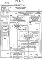
- Fig. 1 is a view for explaining the arrangement of an absolute encoder and a signal processing algorithm according to the first embodiment.
- a light beam emitted by a light-emitting element LED is converted into a collimated light beam by a collimator lens LNS, and illuminates a scale SCL having an array of marks.
- the array of marks of the scale SCL is represented by, for example, a grating pattern made to correspond to codes of 1s and 0s.
- the grating pattern is formed depending on the magnitude of the transmittance or reflectance. More specifically, for example, among the transparent portions and non-transparent portions of the grating pattern of the scale SCL, the transparent portions are selectively provided with a semitransparent film.
- Transmitted light is projected onto a light-receiving element array PDA of an encoder head EH.
- a 16-bit M-sequence (maximal length sequence) or M-sequence code is used.
- the encoder head EH functions as a detector which detects part of the array of marks of the scale, and outputs a data sequence corresponding to it. Note that an encoder head controller CTL controls driving of the encoder head EH.
- 12 elements correspond to one period of the bright/dark pattern.
- the light-receiving element array PDA receives light for 20 periods.
- the light-receiving element array PDA outputs an amplitude modulation periodic signal for 240 elements.
- the amplitude modulation periodic signal is transferred to a signal processor SP, undergoes analog-to-digital conversion by an analog-to-digital converter 101, and is then transferred to the following two calculation blocks.
- a coded data calculator 102 After selecting in advance an element corresponding to a local maximum value, a coded data calculator 102 compares the output of the element with a threshold, and calculates a coded data sequence.
- the coded data sequence is obtained by extracting 18 bits of a central portion of information obtained by demodulating a specific region for 20 bits of the scale in which the grating pattern is formed according to the 16-bit M-sequence code indicating transparent/semitransparent portions. Based on this information, the absolute position information of an integer part is acquired by calculation (to be described later).
- a phase calculator 103 calculates the inner products of the periodic signal waveform having undergone amplitude modulation and two reference phase periodic signal waveforms, and obtains the total sum of the inner products. After that, the phase calculator 103 generates incremental encoder A-phase and B-phase signals from the obtained total sum, and obtains a phase ⁇ by performing arc tangent calculation.
- the phase ⁇ indicates the absolute position information of a fraction part, and serves as an interpolation signal. Note that the present invention relates to code demodulation and thus a description of phase calculation will be omitted.
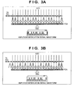
- Figs. 2A to 2C, 3A, and 3B show a case in which the amplitude modulation periodic signal moves (changes) along with movement of the scale SCL.
- Figs. 2A to 3B show an example in which the position of the scale moves leftward by one pitch at times T1, T2, T3, T4, and T5. Since the M-sequence code is directly recorded on the scale, if the scale shifts leftward on the sheet surface by one bit (one grating pitch), the M-sequence code shifts by one bit accordingly. By repeating this operation, the same code sequence is obtained. This is because the M-sequence code is one of cyclic codes.
- the period length is indicated by 2N by representing the number of bits by N, and adding a code sequence of 0s.
- the M-sequence code is a 16-bit M-sequence code
- the pitch of the transparent/non-transparent portions of the scale is 80 ⁇ m.
- a length of 5.2 m can be represented by 65536 absolute positions in steps of 80 ⁇ m.
- the absolute position information is generally more useful when it is sequentially represented from 0 in the ascending order of 1, 2, 3,..., 65536 or in the descending order. In general, therefore, the M-sequence code is converted into a pure binary code, and then output as absolute position information.
- a pure binary converter 104 uses a table in which the correspondence between a reference data sequence and the absolute position information of the scale is described for each of a plurality of reference data sequences. This table is stored in a memory 150 serving as a storage unit. Each of the plurality of reference data sequences in the table is a data sequence obtained by sequentially shifting (by, for example, one bit) the M-sequence code in the grating pattern and extracting it.
- the pure binary converter 104 converts a data sequence into a pure binary by designating an address in the memory 150, and referring to data at the address. For example, the pure binary converter 104 associates the M-sequence code with addresses in the memory. If the M-sequence code is a 16-bit M-sequence code, the number of addresses is 65536.
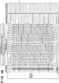
- the pure binary converter 104 adopts a method of setting absolute position information as an address, and holding code sequence data at the address, as shown in Figs. 4A to 7 . Furthermore, for example, in the initial state, the M-sequence code is stored as code sequence data at an address, and the M-sequence code is partially rewritten according to a rewriting algorithm (to be described later) to allow deviation from the rule of the M-sequence code.
- the pure binary converter 104 includes, for example, a table which sequentially stores a 16-bit M-sequence code by 18-bit data in correspondence with respective 65536 addresses. Each 18-bit data is set as reference data.
- a processor 105 collates the acquired coded data sequence with each reference data sequence. That is, a reference data sequence matching the coded data sequence is searched for. Assume that the processing starts from a portion of the scale where there is no flaw, stain, or dust (see Fig. 2A ). In this case, only one completely matched reference data is found (105a), and an address value corresponding to the portion is decided as absolute position information (106). For example, in Fig. 4A corresponding to Fig. 2A , the address of the reference data matching the coded data at time T1 is 1238, and is decided as the absolute position of an integer part. After that, based on the decided absolute position of the integer part and the absolute position of the fraction part decided by the phase calculator 103, the absolute position is calculated and decided (107), and the absolute position information is output (108).
- the absolute encoder When the absolute encoder is used for control processing, measurement is performed at a given interval. Therefore, for example, a code pattern is read by sampling at an interval of 10 ⁇ s. At this time, if the moving amount of the scale within one sampling period is sufficiently small, the next address value should be near the preceding address value. A partial search for a portion where the coded data matches reference data is executed only within a range near the preceding address value. If reference data matching the coded data is found, absolute position information (address value) is output. In general (when there is no flaw or dust), by repeating the above processing, it is possible to output absolute position information at an interval of 10 ⁇ s.
- a partial search is executed in five regions within a range of ⁇ 2 of the preceding position, it can be completed in about five clocks.
- the time is about 0.05 ⁇ s, thereby exerting no influence on the sampling interval of 10 ⁇ s.
- the search range may be widened, narrowed, or offset based on speed information.
- Fig. 4B shows a state at next sampling time T2 (see Fig. 2B ). Referring to Fig. 4B , as a result of executing a search by setting, as a search region, five regions including the address "1238" of the preceding absolute position, the coded data matches reference data at an address "1239". Therefore, the absolute position information of the integer part indicates 1239.
- the signal processor SP includes a digital error detector 109 which detects a digital error of the coded data sequence.
- the digital error detector 109 can detect an error based on the degree of correlation between the coded data sequence and each reference data sequence. If, for example, the acquired 18-bit coded data sequence does not match a reference data sequence (105b), the digital error detector 109 searches for the reference data sequence which does not match the coded data sequence at only a predetermined position.
- the predetermined position indicates, for example, a position including a predetermined number of bits from the most significant bit (MSB) or least significant bit (LSB) of the reference data sequence. That is, the digital error detector 109 determines whether the mismatch portion is in an edge portion or adjacent to it.
- the digital error detector 109 determines a conditional match (109a), and decides the address of the conditional match as absolute position information. On the other hand, if the above condition is not satisfied, the digital error detector 109 sends an error notification indicating that correct position information cannot be output (110).
- a rewriting unit 111 rewrites the reference data at the address of the conditional match by the read data. Furthermore, the rewriting unit 111 completes rewriting of the corresponding portions of the reference data at 18 adjacent addresses before next sampling.
- Fig. 5B shows this rewriting processing.
- an absolute encoder which outputs absolute position information while rewriting reference data is implemented.
- the table of the pure binary converter 104 further includes a field of the rewriting count of reference data at each address.
- the signal processor SP can count up the rewriting count (112), and output the rewriting count (113).
- Figs. 4A to 7 exemplify the value of a rewriting count counter.
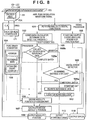
- Fig. 8 is a view for explaining the arrangement of an absolute encoder and a signal processing algorithm according to the second embodiment. Steps until coded data is acquired are the same as in the first embodiment.
- a digital error detector 109 calculates a "Hamming distance" indicating the degree of matching of codes.
- a reference data sequence having a smallest Hamming distance is adopted, and an address at which the reference data sequence is stored is output as absolute position information. That is, a process of selecting reference data having a smallest Hamming distance from reference data including completely matched reference data (whose Hamming distance is 0) is adopted.
- the Hamming distance exceeds a predetermined upper limit value, an error notification (110) indicating that correct position information cannot be output may be sent.
- the upper limit of the Hamming distance is 3 (209).
- the reference data sequence After the reference data sequence is decided based on the Hamming distance, only a mismatch portion needs to be rewritten, similarly to the first embodiment.
- the reference data sequence may be always overwritten and saved, as a matter of course. Similarly, it is necessary to rewrite reference data at 18 adjacent addresses. These rewriting operations are performed in about 20 clocks, and completed before next sampling.
- the scale has further moved, and thus the error portion caused by a flaw/dust has also moved. Since, however, the reference data have already been rewritten, if there is no new flaw/dust in the edge portion of the 18-bit data, and a matched portion always exists. Alternatively, if there is another abnormality in the edge portion, the portion of the reference data is rewritten in the same manner, and the corresponding portions of the reference data at 18 addresses following the address are rewritten. As a result, a portion matching the next reference data always exists.
- the second embodiment is advantageous in simplifying the algorithm, as compared with the first embodiment.
- the same reference data may exist in a plurality of portions.
- a mark indicating that a rewriting operation has been performed is added to the reference data. More preferably, a function of recording a rewriting count for each address is provided. Note that the rewritten reference data includes rewritten reference data according to the relationship between the data.
- the rewriting count counter is assigned to bits added to the reference data. When a rewriting operation is performed, the count is incremented. When the encoder is operated for the first time, the mark of reference data matching read data is confirmed. If the mark indicates 1 or more, an error notification indicating that "correct absolute position information cannot be output" can be sent, thereby performing processing so as to start from another portion.
- the rewriting count can also be used as an index of cleaning or replacement of the scale.
Landscapes
- Physics & Mathematics (AREA)
- General Physics & Mathematics (AREA)
- Transmission And Conversion Of Sensor Element Output (AREA)
- Optical Transform (AREA)
Description
- The present invention relates to an absolute encoder.
- Conventionally, an absolute encoder is used to measure the stage position of an apparatus. An absolute linear encoder records, on a scale, a pattern made to correspond to codes of 1s and 0s, and optically or electromagnetically detects the pattern. Japanese Patent Laid-Open No.
2012-037392 - Since the reflectance may change due to the influence of a defect in the scale (dust on the scale, a flaw in the grating, or the like) to cause erroneous code detection, there is known a method of detecting such error and outputting a warning.
- In Japanese Patent Laid-Open No.
03-274414
In the method described in Japanese Patent Laid-Open No.03-274414
EP 1 876 424 A2
DE 195 06 019 A1 discloses a method of operating an optical steering angle sensor in which, by a stationary sensor unit having a plurality of optical elements, code words are detected as bit sequences of a code track. - The present invention provides, for example, an absolute encoder advantageous in accuracy of an output thereof against a defect in a scale thereof.
- The present invention in its one aspect provides an absolute encoder as specified in
claims 1 to 10. - Further features of the present invention will become apparent from the following description of exemplary embodiments (with reference to the attached drawings).
-
-
Fig. 1 is a view for explaining the arrangement of an absolute encoder and a signal processing algorithm according to the first embodiment; -
Figs. 2A to 2C are views for explaining a variation in waveform of a light-receiving element array caused by movement of a scale; -
Figs. 3A and 3B are views for explaining a variation in waveform of the light-receiving element array caused by movement of the scale; -
Figs. 4A and4B are views for explaining the relationship between a variation in coded data and collated reference data and rewriting of the reference data; -
Figs. 5A and5B are views for explaining the relationship between a variation in coded data and the collated reference data and rewriting of the reference data; -
Figs. 6A and6B are views for explaining the relationship between a variation in coded data and the collated reference data and rewriting of the reference data; -
Fig. 7 is a view for explaining the relationship between a variation in coded data and the collated reference data and rewriting of the reference data; and -
Fig. 8 is a view for explaining the arrangement of an absolute encoder and a signal processing algorithm according to the second embodiment. - Various exemplary embodiments, features, and aspects of the invention will be described in detail below with reference to the drawings.
- Embodiments of the present invention will be described in detail below with reference to the accompanying drawings. The present invention is not limited to the following embodiments, and these embodiments are merely practical examples advantageous when carrying out the present invention. Also, not all combinations of features explained in the following embodiments are essential for the present invention to solve the problem. Note that the same reference numerals denote the same members throughout the drawings, and a repetitive description thereof will not be given.
-
Fig. 1 is a view for explaining the arrangement of an absolute encoder and a signal processing algorithm according to the first embodiment. A light beam emitted by a light-emitting element LED is converted into a collimated light beam by a collimator lens LNS, and illuminates a scale SCL having an array of marks. The array of marks of the scale SCL is represented by, for example, a grating pattern made to correspond to codes of 1s and 0s. The grating pattern is formed depending on the magnitude of the transmittance or reflectance. More specifically, for example, among the transparent portions and non-transparent portions of the grating pattern of the scale SCL, the transparent portions are selectively provided with a semitransparent film. Transmitted light is projected onto a light-receiving element array PDA of an encoder head EH. As a rule for providing a semitransparent film, for example, a 16-bit M-sequence (maximal length sequence) or M-sequence code is used. The encoder head EH functions as a detector which detects part of the array of marks of the scale, and outputs a data sequence corresponding to it. Note that an encoder head controller CTL controls driving of the encoder head EH. - Referring to
Fig. 1 , an opening in a portion of the scale SCL, where horizontal lines are shown, indicates a semitransparent film. Therefore, a bright/dark pattern whose light amount is partially halved by the semitransparent film is projected onto the light-receiving element array PDA. In the light-receiving element array PDA, 12 elements correspond to one period of the bright/dark pattern. The light-receiving element array PDA receives light for 20 periods. Thus, the light-receiving element array PDA outputs an amplitude modulation periodic signal for 240 elements. The amplitude modulation periodic signal is transferred to a signal processor SP, undergoes analog-to-digital conversion by an analog-to-digital converter 101, and is then transferred to the following two calculation blocks. - After selecting in advance an element corresponding to a local maximum value, a coded
data calculator 102 compares the output of the element with a threshold, and calculates a coded data sequence. The coded data sequence is obtained by extracting 18 bits of a central portion of information obtained by demodulating a specific region for 20 bits of the scale in which the grating pattern is formed according to the 16-bit M-sequence code indicating transparent/semitransparent portions. Based on this information, the absolute position information of an integer part is acquired by calculation (to be described later). - A
phase calculator 103 calculates the inner products of the periodic signal waveform having undergone amplitude modulation and two reference phase periodic signal waveforms, and obtains the total sum of the inner products. After that, thephase calculator 103 generates incremental encoder A-phase and B-phase signals from the obtained total sum, and obtains a phase θ by performing arc tangent calculation. The phase θ indicates the absolute position information of a fraction part, and serves as an interpolation signal. Note that the present invention relates to code demodulation and thus a description of phase calculation will be omitted. -
Figs. 2A to 2C, 3A, and 3B show a case in which the amplitude modulation periodic signal moves (changes) along with movement of the scale SCL.Figs. 2A to 3B show an example in which the position of the scale moves leftward by one pitch at times T1, T2, T3, T4, and T5. Since the M-sequence code is directly recorded on the scale, if the scale shifts leftward on the sheet surface by one bit (one grating pitch), the M-sequence code shifts by one bit accordingly. By repeating this operation, the same code sequence is obtained. This is because the M-sequence code is one of cyclic codes. The period length is indicated by 2N by representing the number of bits by N, and adding a code sequence of 0s. Assume that the M-sequence code is a 16-bit M-sequence code, and the pitch of the transparent/non-transparent portions of the scale is 80 µm. In this case, a length of 5.2 m can be represented by 65536 absolute positions in steps of 80 µm. Note that the absolute position information is generally more useful when it is sequentially represented from 0 in the ascending order of 1, 2, 3,..., 65536 or in the descending order. In general, therefore, the M-sequence code is converted into a pure binary code, and then output as absolute position information. - A pure
binary converter 104 uses a table in which the correspondence between a reference data sequence and the absolute position information of the scale is described for each of a plurality of reference data sequences. This table is stored in amemory 150 serving as a storage unit. Each of the plurality of reference data sequences in the table is a data sequence obtained by sequentially shifting (by, for example, one bit) the M-sequence code in the grating pattern and extracting it. The purebinary converter 104 converts a data sequence into a pure binary by designating an address in thememory 150, and referring to data at the address. For example, the purebinary converter 104 associates the M-sequence code with addresses in the memory. If the M-sequence code is a 16-bit M-sequence code, the number of addresses is 65536. - If, however, dust adheres to the transparent portion of the scale, the amount of transmitted light decreases. Consequently, for example, in a portion where a code of 1 should be originally determined, a code of 0 may be erroneously determined. The relationship between the codes of the erroneously read 16-bit code sequence deviates from the rule of the M-sequence, and the same code sequence also exists in a portion different from the original portion. Therefore, if a method of associating such M-sequence code with the addresses and referring to the data is used, wrong pure binary absolute position information may be output in a flawed or dirty portion. Note that the flawed or dirty portion of the scale is represented by "x" in
Figs. 2A to 2C, 3A, and 3B . - To solve the above problem, the pure
binary converter 104 adopts a method of setting absolute position information as an address, and holding code sequence data at the address, as shown inFigs. 4A to 7 . Furthermore, for example, in the initial state, the M-sequence code is stored as code sequence data at an address, and the M-sequence code is partially rewritten according to a rewriting algorithm (to be described later) to allow deviation from the rule of the M-sequence code. - A data processing algorithm according to this embodiment will be described below.
- According to a simultaneously calculated phase calculation value, 18 bits of a central portion of demodulated information for 20 bits are selected, and set as code data. The pure
binary converter 104 includes, for example, a table which sequentially stores a 16-bit M-sequence code by 18-bit data in correspondence with respective 65536 addresses. Each 18-bit data is set as reference data. - A
processor 105 collates the acquired coded data sequence with each reference data sequence. That is, a reference data sequence matching the coded data sequence is searched for. Assume that the processing starts from a portion of the scale where there is no flaw, stain, or dust (seeFig. 2A ). In this case, only one completely matched reference data is found (105a), and an address value corresponding to the portion is decided as absolute position information (106). For example, inFig. 4A corresponding toFig. 2A , the address of the reference data matching the coded data at time T1 is 1238, and is decided as the absolute position of an integer part. After that, based on the decided absolute position of the integer part and the absolute position of the fraction part decided by thephase calculator 103, the absolute position is calculated and decided (107), and the absolute position information is output (108). - When the absolute encoder is used for control processing, measurement is performed at a given interval. Therefore, for example, a code pattern is read by sampling at an interval of 10 µs. At this time, if the moving amount of the scale within one sampling period is sufficiently small, the next address value should be near the preceding address value. A partial search for a portion where the coded data matches reference data is executed only within a range near the preceding address value. If reference data matching the coded data is found, absolute position information (address value) is output. In general (when there is no flaw or dust), by repeating the above processing, it is possible to output absolute position information at an interval of 10 µs.
- Note that if a partial search is executed in five regions within a range of ±2 of the preceding position, it can be completed in about five clocks. For an FPGA calculation system using a 100-MHz clock signal, therefore, the time is about 0.05 µs, thereby exerting no influence on the sampling interval of 10 µs. Note that the search range may be widened, narrowed, or offset based on speed information.
Fig. 4B shows a state at next sampling time T2 (seeFig. 2B ). Referring toFig. 4B , as a result of executing a search by setting, as a search region, five regions including the address "1238" of the preceding absolute position, the coded data matches reference data at an address "1239". Therefore, the absolute position information of the integer part indicates 1239. - As shown in
Figs. 2C and5A , when the scale includes a defect such as a flaw or dust, no matched reference data is found within the search range even by executing a search. Processing in this case according to this embodiment will be described below with reference to the flowchart shown inFig. 1 . - The signal processor SP includes a
digital error detector 109 which detects a digital error of the coded data sequence. Thedigital error detector 109 can detect an error based on the degree of correlation between the coded data sequence and each reference data sequence. If, for example, the acquired 18-bit coded data sequence does not match a reference data sequence (105b), thedigital error detector 109 searches for the reference data sequence which does not match the coded data sequence at only a predetermined position. The predetermined position indicates, for example, a position including a predetermined number of bits from the most significant bit (MSB) or least significant bit (LSB) of the reference data sequence. That is, thedigital error detector 109 determines whether the mismatch portion is in an edge portion or adjacent to it. If the mismatch portion is in an edge portion or adjacent to it, thedigital error detector 109 determines a conditional match (109a), and decides the address of the conditional match as absolute position information. On the other hand, if the above condition is not satisfied, thedigital error detector 109 sends an error notification indicating that correct position information cannot be output (110). - After the absolute position information is decided, a
rewriting unit 111 rewrites the reference data at the address of the conditional match by the read data. Furthermore, therewriting unit 111 completes rewriting of the corresponding portions of the reference data at 18 adjacent addresses before next sampling.Fig. 5B shows this rewriting processing. - At the time of the next sampling, the scale has further moved, and thus the error portion caused by a flaw/dust has also moved. Note that the reference data have already been rewritten, as described above. Therefore, if there is no new flaw/dust in the edge portion of the 18-bit data, matched reference data always exists in a newly set search region. Alternatively, if there is another abnormality in the edge portion, the portion of the reference data is rewritten in the same manner, and the corresponding portions of the reference data at 18 addresses following the address are rewritten. With this processing, a portion matching the next reference data always exists.
Figs. 3A ,6A , and6B show these cases.Figs. 3B and7 show a case in which the scale further moves. - As described above, an absolute encoder which outputs absolute position information while rewriting reference data is implemented.
- Note that the user is reassured by outputting information indicating that reference data have been rewritten and rewriting count information. In this embodiment, the table of the pure
binary converter 104 further includes a field of the rewriting count of reference data at each address. The signal processor SP can count up the rewriting count (112), and output the rewriting count (113).Figs. 4A to 7 exemplify the value of a rewriting count counter. - According to the above-described first embodiment, the following effects can be obtained.
- (1) Even if there is a small defect (flaw/dust) in the scale, it is possible to continuously output correct absolute position information.
- (2) Since information of a defect (flaw/dust) in the scale is reflected in reference data, when the reference data is repeatedly used, it is not necessary to take measures (rewriting) against a mismatch of data every time, thereby enabling a highspeed operation.
- (3) Since reference data including defect information of the scale is updated, it is possible to perform quality control by extracting the defect information. For example, when the defect rate exceeds a predetermined value, it is possible to determine the time for cleaning or replacement.
-
Fig. 8 is a view for explaining the arrangement of an absolute encoder and a signal processing algorithm according to the second embodiment. Steps until coded data is acquired are the same as in the first embodiment. - In this embodiment, if there is a flaw or defect in a scale, and no completely matched reference data is found within a search range even by executing a search, a
digital error detector 109 calculates a "Hamming distance" indicating the degree of matching of codes. At this time, for example, a reference data sequence having a smallest Hamming distance is adopted, and an address at which the reference data sequence is stored is output as absolute position information. That is, a process of selecting reference data having a smallest Hamming distance from reference data including completely matched reference data (whose Hamming distance is 0) is adopted. - Note that if the Hamming distance exceeds a predetermined upper limit value, an error notification (110) indicating that correct position information cannot be output may be sent. In the flowchart shown in
Fig. 8 , the upper limit of the Hamming distance is 3 (209). - After the reference data sequence is decided based on the Hamming distance, only a mismatch portion needs to be rewritten, similarly to the first embodiment. The reference data sequence may be always overwritten and saved, as a matter of course. Similarly, it is necessary to rewrite reference data at 18 adjacent addresses. These rewriting operations are performed in about 20 clocks, and completed before next sampling.
- At the time of the next sampling, the scale has further moved, and thus the error portion caused by a flaw/dust has also moved. Since, however, the reference data have already been rewritten, if there is no new flaw/dust in the edge portion of the 18-bit data, and a matched portion always exists. Alternatively, if there is another abnormality in the edge portion, the portion of the reference data is rewritten in the same manner, and the corresponding portions of the reference data at 18 addresses following the address are rewritten. As a result, a portion matching the next reference data always exists.
- The second embodiment is advantageous in simplifying the algorithm, as compared with the first embodiment.
- In the first and second embodiments, a case in which measurement correctly starts when the scale includes no flaw or dust has been assumed. In fact, however, measurement may start from a portion of the scale where there exists a flaw/dust. Therefore, the following processing may be added.
- If coded data for 18 bits including a portion of the scale where there exists a flow/dust is acquired, it does not match reference data at high probability. Therefore, in the first and second embodiments, an error notification indicating that "correct absolute position information cannot be output" is immediately sent. The user of the encoder cleans the portion of the scale or performs processing so as to start from another portion.
- However, some reference data including incompletely matched reference data in the second embodiment is erroneously selected, a problem arises. In this case, even if truly incorrect reference data is adopted, no matched reference data is found within a search region in next sampling. In this case as well, it is possible to avoid erroneous use by sending an error notification indicating that "correct absolute position information cannot be output".
- Assuming that processing restarts from a portion where reference data was rewritten for a flaw/dust in the scale while the encoder was used in the past, the same reference data may exist in a plurality of portions. To solve this problem, in this embodiment, a mark indicating that a rewriting operation has been performed is added to the reference data. More preferably, a function of recording a rewriting count for each address is provided. Note that the rewritten reference data includes rewritten reference data according to the relationship between the data.
- The rewriting count counter is assigned to bits added to the reference data. When a rewriting operation is performed, the count is incremented. When the encoder is operated for the first time, the mark of reference data matching read data is confirmed. If the mark indicates 1 or more, an error notification indicating that "correct absolute position information cannot be output" can be sent, thereby performing processing so as to start from another portion. The rewriting count can also be used as an index of cleaning or replacement of the scale.
- By adding the above function to the first or second embodiment, it is possible to use the absolute encoder more safely.
- Various modifications and changes can be made to the above-described embodiments within the spirit and scope of the present invention. Examples which can be modified or changed will be explained below.
- 1. In the first and second embodiments, the transmissive scale is used. However, a reflective scale may be used, and the reflectance may be determined according to a code of 1 or 0. Although the optical system projects diverging light onto the scale, and projects an enlarged image onto a light-receiving element array, the optical system can be changed to perform, for example, unit-magnification projection by collimated light illumination, as appropriate. Although the amount of light reaching the light-receiving element is determined according to a code of 1 or 0, a small light amount includes zero.
- 2. In the first and second embodiments, code demodulation is determined based on the threshold. However, determination may be performed and read data may be acquired by another method of, for example, paying attention to a variation in periodic signal waveform between adjacent data.
- 3. In the first and second embodiments, the light-receiving element array PDA is configured to detect one "bright-dark" cycle by the 12 light-receiving elements. The number of light-receiving elements which detect one "bright-dark" cycle may be changed to 3, 4, 6, 8, or the like.
- 4. In the above-described embodiments, waves of the amplitude modulation periodic waveform for 20 periods are captured, 18-bit data of a central portion of 20-bit data demodulated from the waves is set as read data, and a portion where the read data matches reference data is then searched for. However, the number of captured waves of the amplitude modulation periodic waveform and the number of bits of the read data need only be equal to or larger than the number of bits of the M-sequence code, and may be changed to another number.
- 5. In the above-described embodiments, the M-sequence code is used as a code sequence on the scale. Other cyclic codes and data recording absolute position code information including a set of an address and data can be used. In this case as well, by providing the similar collation process, reference data selection process, a function of confirming and outputting an absolute position corresponding to reference data, and a reference data rewriting function in the pure binary converter, it is possible to prevent erroneous detection caused by a flaw/dust on the scale, in the completely same manner.
- 6. A detector including a light-receiving element array has been exemplified as a
detector 1. The present invention, however, is not limited to this, and the detector can include an array of various elements in accordance with the characteristics of marks formed in ascale 2. That is, the elements may detect any physical amounts corresponding to the characteristics for discriminating a plurality of kinds of marks. Marks of an array of marks formed in the scale includes a plurality of kinds of marks, characteristics of which are different from each other, and are arranged with gaps (spaces or spacings) thereamong. For example, if a plurality of kinds of (permanent) magnets for generating magnetic fields of different strengths are included as the plurality of kinds of marks formed in the scale, thedetector 1 can adopt an array of magnetic (magnetic field) detection elements such as Hall elements. - While the present invention has been described with reference to exemplary embodiments, it is to be understood that the invention is not limited to the disclosed exemplary embodiments. The scope of the following claims is to be accorded the broadest interpretation so as to encompass all such modifications and equivalent structures and functions.
Claims (10)
- An absolute encoder comprising:a scale (SCL) including an array of marks;a detector (EH) configured to detect a part of the array of marks and output a data sequence corresponding to the part; anda processor (SP) storing information indicating a correspondence between each of a plurality of code sequences and an absolute coordinate of motion of the scale, and configured to output information of the absolute coordinate based on the data sequence and the information,wherein the processor is configured to detect an error of the data sequence based on a degree of correlation between the data sequence and each of code sequences as a part of the plurality of code sequences in the information,characterized by being further configured to perform rewriting of a plurality of code sequences as a part of the plurality of code sequences in the information based on the detected error.
- The encoder according to claim 1, wherein the processor is configuredto search for a code sequence with respect to the data sequence and decide the absolute coordinate according to a code sequence having a highest degree of correlation with the data sequence,to detect an error by determining a mismatch portion of the code sequence corresponding to the decided absolute coordinate, andto perform the rewriting by using the detected data sequence to overwrite therewith the mismatch portion of the code sequence corresponding to the decided absolute coordinate and corresponding mismatch portions of a plurality of code sequences corresponding to absolute coordinates adjacent to the decided absolute coordinate.
- The encoder according to claim 1 or 2, wherein the processor is configured to detect an error in a predetermined number of most significant bits and a predetermined number of least significant bits in the data sequence.
- The encoder according to any one of claims 1 to 3, whereinthe plurality of code sequences are a plurality of code sequences obtained by sequentially shifting and extracting a code sequence from an M-sequence, anda plurality of the absolute coordinate are represented by a plurality of binary codes in one of an ascending order and descending order.
- The encoder according to claim 4, wherein the absolute coordinate is represented by an address for a storage, in the processor, storing the information.
- The encoder according to claim 2, wherein the processor is configured to output an error based on the degree of correlation.
- The encoder according to any one of claims 1 to 6, wherein the information includes information of number of times of the rewriting with respect to each of the plurality of code sequences.
- The encoder according to claim 7, wherein the processor is configured to output the information of the number of times.
- The encoder according to claim 2, wherein the processor is configured to use a Hamming distance as the degree of correlation.
- The encoder according to any one of claims 1 to 9, wherein marks of the array of marks include a plurality of kinds of marks, characteristics of which are different from each other, and are arranged with gaps thereamong.
Applications Claiming Priority (1)
| Application Number | Priority Date | Filing Date | Title |
|---|---|---|---|
| JP2014087591A JP6320149B2 (en) | 2014-04-21 | 2014-04-21 | Absolute encoder |
Publications (2)
| Publication Number | Publication Date |
|---|---|
| EP2937671A1 EP2937671A1 (en) | 2015-10-28 |
| EP2937671B1 true EP2937671B1 (en) | 2017-06-14 |
Family
ID=52875398
Family Applications (1)
| Application Number | Title | Priority Date | Filing Date |
|---|---|---|---|
| EP15001094.0A Active EP2937671B1 (en) | 2014-04-21 | 2015-04-15 | Absolute encoder |
Country Status (3)
| Country | Link |
|---|---|
| US (1) | US9810555B2 (en) |
| EP (1) | EP2937671B1 (en) |
| JP (1) | JP6320149B2 (en) |
Families Citing this family (6)
| Publication number | Priority date | Publication date | Assignee | Title |
|---|---|---|---|---|
| US9792688B2 (en) * | 2015-10-02 | 2017-10-17 | Mitsubishi Electric Corporation | Position detection device |
| CN106918307B (en) * | 2017-01-25 | 2019-02-22 | 哈尔滨理工大学 | A kind of reliable absolutely simulation code search method |
| DE102017102494A1 (en) * | 2017-02-08 | 2018-08-09 | Beckhoff Automation Gmbh | Position determination of a movable element |
| JP2019158848A (en) * | 2018-03-16 | 2019-09-19 | 富士電機株式会社 | Absolute location information detection device, and absolute location information detection device control method |
| CN112436907A (en) * | 2020-12-09 | 2021-03-02 | 中国电子科技集团公司第五十四研究所 | Digital phased array transmitting channel consistency rapid calibration system based on m sequence |
| DE102022115039B3 (en) * | 2022-06-15 | 2023-04-20 | Sick Ag | Device and method for monitoring a functionality of a device for position, length or angle determination |
Family Cites Families (15)
| Publication number | Priority date | Publication date | Assignee | Title |
|---|---|---|---|---|
| AT379893B (en) * | 1984-07-03 | 1986-03-10 | R S F Elektronik Ohg Rechtsfor | METHOD FOR DIGITAL ELECTRIC LENGTH OR ANGLE MEASUREMENT AND CIRCUIT ARRANGEMENT FOR CARRYING OUT THIS METHOD |
| US4914437A (en) * | 1986-12-04 | 1990-04-03 | Regents Of The University Of California | Encoder for measuring both incremental and absolute positions of moving elements |
| JPH03274414A (en) | 1990-03-26 | 1991-12-05 | Nikon Corp | One track type absolute encoder capable of detecting abnormal situation |
| JPH04143620A (en) * | 1990-10-05 | 1992-05-18 | Matsushita Electric Ind Co Ltd | Position detector |
| DE19506019C2 (en) * | 1995-02-22 | 2000-04-13 | Telefunken Microelectron | Method for operating an optical steering angle sensor |
| US6127948A (en) * | 1998-06-17 | 2000-10-03 | Gurley Precision Instruments, Inc. | Bidirectional synthesis of pseudorandom sequences for arbitrary encoding resolutions |
| JP4223195B2 (en) * | 2000-02-10 | 2009-02-12 | オークマ株式会社 | Absolute encoder |
| DE10244547B4 (en) * | 2002-09-25 | 2010-11-11 | Dr. Johannes Heidenhain Gmbh | Method and position measuring device for determining an absolute position |
| US7034283B2 (en) * | 2003-03-05 | 2006-04-25 | Raytheon Company | Absolute incremental position encoder and method |
| JP5021244B2 (en) * | 2006-07-03 | 2012-09-05 | 株式会社ミツトヨ | Displacement detection encoder |
| JP5286584B2 (en) * | 2007-06-19 | 2013-09-11 | 株式会社ミツトヨ | Absolute position measuring encoder |
| DE102007061287A1 (en) | 2007-12-19 | 2009-06-25 | Dr. Johannes Heidenhain Gmbh | Position measuring device and method for absolute position determination |
| US8698892B2 (en) * | 2009-04-03 | 2014-04-15 | Csem Centre Suisse D'electronique Et De Microtechnique Sa - Recherche Et Developpement | One-dimension position encoder |
| GB0909724D0 (en) * | 2009-06-05 | 2009-07-22 | Renishaw Plc | Position measurement encoder and method of operation |
| JP5379761B2 (en) | 2010-08-06 | 2013-12-25 | キヤノン株式会社 | Absolute encoder |
-
2014
- 2014-04-21 JP JP2014087591A patent/JP6320149B2/en active Active
-
2015
- 2015-04-15 EP EP15001094.0A patent/EP2937671B1/en active Active
- 2015-04-17 US US14/689,329 patent/US9810555B2/en active Active
Non-Patent Citations (1)
| Title |
|---|
| None * |
Also Published As
| Publication number | Publication date |
|---|---|
| JP6320149B2 (en) | 2018-05-09 |
| US20150300847A1 (en) | 2015-10-22 |
| US9810555B2 (en) | 2017-11-07 |
| JP2015206688A (en) | 2015-11-19 |
| EP2937671A1 (en) | 2015-10-28 |
Similar Documents
| Publication | Publication Date | Title |
|---|---|---|
| EP2937671B1 (en) | Absolute encoder | |
| JP6074392B2 (en) | Position encoder apparatus and operation method | |
| US7164120B2 (en) | Position measuring instrument | |
| US6987465B2 (en) | Procedure for the determination of an absolute position | |
| US20120283986A1 (en) | System and Method for Measuring Positions | |
| US10209104B2 (en) | Absolute encoder, processing method, program, driving apparatus, and industrial machine | |
| JP2008268215A (en) | Encoder | |
| US5675129A (en) | Initial track recovery in position-sensing systems that use windowing patterns | |
| JP2008014665A (en) | Displacement detecting encoder | |
| EP2963393B1 (en) | Absolute encoder | |
| JP6338360B2 (en) | Absolute encoder, signal processing method, and program | |
| JP6149740B2 (en) | Absolute encoder | |
| US8136258B2 (en) | Absolute position sensor with serial reading | |
| DREQ | COMPLETE MATCH 109 | |
| US7434740B2 (en) | Method and apparatus for position detection | |
| KR100575124B1 (en) | Linear Encoder for Detecting Long Span | |
| US9322675B2 (en) | Absolute encoder and method of obtaining absolute position by a plurality of quantized data based on a plurality of extrema | |
| JP2007322301A (en) | Absolute position detector | |
| US10914612B2 (en) | Indexed optical encoder | |
| JPS63266310A (en) | Position detector |
Legal Events
| Date | Code | Title | Description |
|---|---|---|---|
| PUAI | Public reference made under article 153(3) epc to a published international application that has entered the european phase |
Free format text: ORIGINAL CODE: 0009012 |
|
| AK | Designated contracting states |
Kind code of ref document: A1 Designated state(s): AL AT BE BG CH CY CZ DE DK EE ES FI FR GB GR HR HU IE IS IT LI LT LU LV MC MK MT NL NO PL PT RO RS SE SI SK SM TR |
|
| AX | Request for extension of the european patent |
Extension state: BA ME |
|
| RIN1 | Information on inventor provided before grant (corrected) |
Inventor name: ISHIZUKA, KO |
|
| 17P | Request for examination filed |
Effective date: 20160428 |
|
| RBV | Designated contracting states (corrected) |
Designated state(s): AL AT BE BG CH CY CZ DE DK EE ES FI FR GB GR HR HU IE IS IT LI LT LU LV MC MK MT NL NO PL PT RO RS SE SI SK SM TR |
|
| GRAP | Despatch of communication of intention to grant a patent |
Free format text: ORIGINAL CODE: EPIDOSNIGR1 |
|
| INTG | Intention to grant announced |
Effective date: 20161025 |
|
| RAP1 | Party data changed (applicant data changed or rights of an application transferred) |
Owner name: CANON KABUSHIKI KAISHA |
|
| GRAS | Grant fee paid |
Free format text: ORIGINAL CODE: EPIDOSNIGR3 |
|
| GRAJ | Information related to disapproval of communication of intention to grant by the applicant or resumption of examination proceedings by the epo deleted |
Free format text: ORIGINAL CODE: EPIDOSDIGR1 |
|
| GRAL | Information related to payment of fee for publishing/printing deleted |
Free format text: ORIGINAL CODE: EPIDOSDIGR3 |
|
| GRAR | Information related to intention to grant a patent recorded |
Free format text: ORIGINAL CODE: EPIDOSNIGR71 |
|
| INTC | Intention to grant announced (deleted) | ||
| INTG | Intention to grant announced |
Effective date: 20170316 |
|
| GRAA | (expected) grant |
Free format text: ORIGINAL CODE: 0009210 |
|
| AK | Designated contracting states |
Kind code of ref document: B1 Designated state(s): AL AT BE BG CH CY CZ DE DK EE ES FI FR GB GR HR HU IE IS IT LI LT LU LV MC MK MT NL NO PL PT RO RS SE SI SK SM TR |
|
| REG | Reference to a national code |
Ref country code: GB Ref legal event code: FG4D |
|
| REG | Reference to a national code |
Ref country code: CH Ref legal event code: EP Ref country code: AT Ref legal event code: REF Ref document number: 901420 Country of ref document: AT Kind code of ref document: T Effective date: 20170615 |
|
| REG | Reference to a national code |
Ref country code: IE Ref legal event code: FG4D |
|
| REG | Reference to a national code |
Ref country code: DE Ref legal event code: R096 Ref document number: 602015003027 Country of ref document: DE |
|
| REG | Reference to a national code |
Ref country code: NL Ref legal event code: MP Effective date: 20170614 |
|
| REG | Reference to a national code |
Ref country code: LT Ref legal event code: MG4D |
|
| PG25 | Lapsed in a contracting state [announced via postgrant information from national office to epo] |
Ref country code: LT Free format text: LAPSE BECAUSE OF FAILURE TO SUBMIT A TRANSLATION OF THE DESCRIPTION OR TO PAY THE FEE WITHIN THE PRESCRIBED TIME-LIMIT Effective date: 20170614 Ref country code: GR Free format text: LAPSE BECAUSE OF FAILURE TO SUBMIT A TRANSLATION OF THE DESCRIPTION OR TO PAY THE FEE WITHIN THE PRESCRIBED TIME-LIMIT Effective date: 20170915 Ref country code: HR Free format text: LAPSE BECAUSE OF FAILURE TO SUBMIT A TRANSLATION OF THE DESCRIPTION OR TO PAY THE FEE WITHIN THE PRESCRIBED TIME-LIMIT Effective date: 20170614 Ref country code: FI Free format text: LAPSE BECAUSE OF FAILURE TO SUBMIT A TRANSLATION OF THE DESCRIPTION OR TO PAY THE FEE WITHIN THE PRESCRIBED TIME-LIMIT Effective date: 20170614 Ref country code: NO Free format text: LAPSE BECAUSE OF FAILURE TO SUBMIT A TRANSLATION OF THE DESCRIPTION OR TO PAY THE FEE WITHIN THE PRESCRIBED TIME-LIMIT Effective date: 20170914 |
|
| REG | Reference to a national code |
Ref country code: AT Ref legal event code: MK05 Ref document number: 901420 Country of ref document: AT Kind code of ref document: T Effective date: 20170614 |
|
| PG25 | Lapsed in a contracting state [announced via postgrant information from national office to epo] |
Ref country code: BG Free format text: LAPSE BECAUSE OF FAILURE TO SUBMIT A TRANSLATION OF THE DESCRIPTION OR TO PAY THE FEE WITHIN THE PRESCRIBED TIME-LIMIT Effective date: 20170914 Ref country code: LV Free format text: LAPSE BECAUSE OF FAILURE TO SUBMIT A TRANSLATION OF THE DESCRIPTION OR TO PAY THE FEE WITHIN THE PRESCRIBED TIME-LIMIT Effective date: 20170614 Ref country code: NL Free format text: LAPSE BECAUSE OF FAILURE TO SUBMIT A TRANSLATION OF THE DESCRIPTION OR TO PAY THE FEE WITHIN THE PRESCRIBED TIME-LIMIT Effective date: 20170614 Ref country code: RS Free format text: LAPSE BECAUSE OF FAILURE TO SUBMIT A TRANSLATION OF THE DESCRIPTION OR TO PAY THE FEE WITHIN THE PRESCRIBED TIME-LIMIT Effective date: 20170614 Ref country code: SE Free format text: LAPSE BECAUSE OF FAILURE TO SUBMIT A TRANSLATION OF THE DESCRIPTION OR TO PAY THE FEE WITHIN THE PRESCRIBED TIME-LIMIT Effective date: 20170614 |
|
| PG25 | Lapsed in a contracting state [announced via postgrant information from national office to epo] |
Ref country code: RO Free format text: LAPSE BECAUSE OF FAILURE TO SUBMIT A TRANSLATION OF THE DESCRIPTION OR TO PAY THE FEE WITHIN THE PRESCRIBED TIME-LIMIT Effective date: 20170614 Ref country code: SK Free format text: LAPSE BECAUSE OF FAILURE TO SUBMIT A TRANSLATION OF THE DESCRIPTION OR TO PAY THE FEE WITHIN THE PRESCRIBED TIME-LIMIT Effective date: 20170614 Ref country code: AT Free format text: LAPSE BECAUSE OF FAILURE TO SUBMIT A TRANSLATION OF THE DESCRIPTION OR TO PAY THE FEE WITHIN THE PRESCRIBED TIME-LIMIT Effective date: 20170614 Ref country code: EE Free format text: LAPSE BECAUSE OF FAILURE TO SUBMIT A TRANSLATION OF THE DESCRIPTION OR TO PAY THE FEE WITHIN THE PRESCRIBED TIME-LIMIT Effective date: 20170614 Ref country code: CZ Free format text: LAPSE BECAUSE OF FAILURE TO SUBMIT A TRANSLATION OF THE DESCRIPTION OR TO PAY THE FEE WITHIN THE PRESCRIBED TIME-LIMIT Effective date: 20170614 |
|
| PG25 | Lapsed in a contracting state [announced via postgrant information from national office to epo] |
Ref country code: IS Free format text: LAPSE BECAUSE OF FAILURE TO SUBMIT A TRANSLATION OF THE DESCRIPTION OR TO PAY THE FEE WITHIN THE PRESCRIBED TIME-LIMIT Effective date: 20171014 Ref country code: PL Free format text: LAPSE BECAUSE OF FAILURE TO SUBMIT A TRANSLATION OF THE DESCRIPTION OR TO PAY THE FEE WITHIN THE PRESCRIBED TIME-LIMIT Effective date: 20170614 Ref country code: SM Free format text: LAPSE BECAUSE OF FAILURE TO SUBMIT A TRANSLATION OF THE DESCRIPTION OR TO PAY THE FEE WITHIN THE PRESCRIBED TIME-LIMIT Effective date: 20170614 Ref country code: ES Free format text: LAPSE BECAUSE OF FAILURE TO SUBMIT A TRANSLATION OF THE DESCRIPTION OR TO PAY THE FEE WITHIN THE PRESCRIBED TIME-LIMIT Effective date: 20170614 Ref country code: IT Free format text: LAPSE BECAUSE OF FAILURE TO SUBMIT A TRANSLATION OF THE DESCRIPTION OR TO PAY THE FEE WITHIN THE PRESCRIBED TIME-LIMIT Effective date: 20170614 |
|
| REG | Reference to a national code |
Ref country code: DE Ref legal event code: R097 Ref document number: 602015003027 Country of ref document: DE |
|
| PLBE | No opposition filed within time limit |
Free format text: ORIGINAL CODE: 0009261 |
|
| STAA | Information on the status of an ep patent application or granted ep patent |
Free format text: STATUS: NO OPPOSITION FILED WITHIN TIME LIMIT |
|
| PG25 | Lapsed in a contracting state [announced via postgrant information from national office to epo] |
Ref country code: DK Free format text: LAPSE BECAUSE OF FAILURE TO SUBMIT A TRANSLATION OF THE DESCRIPTION OR TO PAY THE FEE WITHIN THE PRESCRIBED TIME-LIMIT Effective date: 20170614 |
|
| 26N | No opposition filed |
Effective date: 20180315 |
|
| PG25 | Lapsed in a contracting state [announced via postgrant information from national office to epo] |
Ref country code: SI Free format text: LAPSE BECAUSE OF FAILURE TO SUBMIT A TRANSLATION OF THE DESCRIPTION OR TO PAY THE FEE WITHIN THE PRESCRIBED TIME-LIMIT Effective date: 20170614 |
|
| PG25 | Lapsed in a contracting state [announced via postgrant information from national office to epo] |
Ref country code: MC Free format text: LAPSE BECAUSE OF FAILURE TO SUBMIT A TRANSLATION OF THE DESCRIPTION OR TO PAY THE FEE WITHIN THE PRESCRIBED TIME-LIMIT Effective date: 20170614 |
|
| REG | Reference to a national code |
Ref country code: CH Ref legal event code: PL |
|
| REG | Reference to a national code |
Ref country code: BE Ref legal event code: MM Effective date: 20180430 |
|
| REG | Reference to a national code |
Ref country code: IE Ref legal event code: MM4A |
|
| PG25 | Lapsed in a contracting state [announced via postgrant information from national office to epo] |
Ref country code: LU Free format text: LAPSE BECAUSE OF NON-PAYMENT OF DUE FEES Effective date: 20180415 |
|
| PG25 | Lapsed in a contracting state [announced via postgrant information from national office to epo] |
Ref country code: CH Free format text: LAPSE BECAUSE OF NON-PAYMENT OF DUE FEES Effective date: 20180430 Ref country code: BE Free format text: LAPSE BECAUSE OF NON-PAYMENT OF DUE FEES Effective date: 20180430 Ref country code: LI Free format text: LAPSE BECAUSE OF NON-PAYMENT OF DUE FEES Effective date: 20180430 |
|
| PG25 | Lapsed in a contracting state [announced via postgrant information from national office to epo] |
Ref country code: FR Free format text: LAPSE BECAUSE OF NON-PAYMENT OF DUE FEES Effective date: 20180430 Ref country code: IE Free format text: LAPSE BECAUSE OF NON-PAYMENT OF DUE FEES Effective date: 20180415 |
|
| PG25 | Lapsed in a contracting state [announced via postgrant information from national office to epo] |
Ref country code: MT Free format text: LAPSE BECAUSE OF NON-PAYMENT OF DUE FEES Effective date: 20180415 |
|
| PG25 | Lapsed in a contracting state [announced via postgrant information from national office to epo] |
Ref country code: TR Free format text: LAPSE BECAUSE OF FAILURE TO SUBMIT A TRANSLATION OF THE DESCRIPTION OR TO PAY THE FEE WITHIN THE PRESCRIBED TIME-LIMIT Effective date: 20170614 |
|
| PG25 | Lapsed in a contracting state [announced via postgrant information from national office to epo] |
Ref country code: PT Free format text: LAPSE BECAUSE OF FAILURE TO SUBMIT A TRANSLATION OF THE DESCRIPTION OR TO PAY THE FEE WITHIN THE PRESCRIBED TIME-LIMIT Effective date: 20170614 |
|
| PG25 | Lapsed in a contracting state [announced via postgrant information from national office to epo] |
Ref country code: CY Free format text: LAPSE BECAUSE OF FAILURE TO SUBMIT A TRANSLATION OF THE DESCRIPTION OR TO PAY THE FEE WITHIN THE PRESCRIBED TIME-LIMIT Effective date: 20170614 Ref country code: HU Free format text: LAPSE BECAUSE OF FAILURE TO SUBMIT A TRANSLATION OF THE DESCRIPTION OR TO PAY THE FEE WITHIN THE PRESCRIBED TIME-LIMIT; INVALID AB INITIO Effective date: 20150415 Ref country code: MK Free format text: LAPSE BECAUSE OF NON-PAYMENT OF DUE FEES Effective date: 20170614 |
|
| PG25 | Lapsed in a contracting state [announced via postgrant information from national office to epo] |
Ref country code: AL Free format text: LAPSE BECAUSE OF FAILURE TO SUBMIT A TRANSLATION OF THE DESCRIPTION OR TO PAY THE FEE WITHIN THE PRESCRIBED TIME-LIMIT Effective date: 20170614 |
|
| PGFP | Annual fee paid to national office [announced via postgrant information from national office to epo] |
Ref country code: GB Payment date: 20230321 Year of fee payment: 9 |
|
| PGFP | Annual fee paid to national office [announced via postgrant information from national office to epo] |
Ref country code: DE Payment date: 20230321 Year of fee payment: 9 |