EP2937595B1 - Gasdruckfeder - Google Patents
Gasdruckfeder Download PDFInfo
- Publication number
- EP2937595B1 EP2937595B1 EP15161830.3A EP15161830A EP2937595B1 EP 2937595 B1 EP2937595 B1 EP 2937595B1 EP 15161830 A EP15161830 A EP 15161830A EP 2937595 B1 EP2937595 B1 EP 2937595B1
- Authority
- EP
- European Patent Office
- Prior art keywords
- gas
- housing
- gas compression
- compression chamber
- piston
- Prior art date
- Legal status (The legal status is an assumption and is not a legal conclusion. Google has not performed a legal analysis and makes no representation as to the accuracy of the status listed.)
- Active
Links
Images

Classifications
-
- F—MECHANICAL ENGINEERING; LIGHTING; HEATING; WEAPONS; BLASTING
- F16—ENGINEERING ELEMENTS AND UNITS; GENERAL MEASURES FOR PRODUCING AND MAINTAINING EFFECTIVE FUNCTIONING OF MACHINES OR INSTALLATIONS; THERMAL INSULATION IN GENERAL
- F16F—SPRINGS; SHOCK-ABSORBERS; MEANS FOR DAMPING VIBRATION
- F16F9/00—Springs, vibration-dampers, shock-absorbers, or similarly-constructed movement-dampers using a fluid or the equivalent as damping medium
- F16F9/32—Details
- F16F9/3292—Sensor arrangements
-
- F—MECHANICAL ENGINEERING; LIGHTING; HEATING; WEAPONS; BLASTING
- F16—ENGINEERING ELEMENTS AND UNITS; GENERAL MEASURES FOR PRODUCING AND MAINTAINING EFFECTIVE FUNCTIONING OF MACHINES OR INSTALLATIONS; THERMAL INSULATION IN GENERAL
- F16F—SPRINGS; SHOCK-ABSORBERS; MEANS FOR DAMPING VIBRATION
- F16F9/00—Springs, vibration-dampers, shock-absorbers, or similarly-constructed movement-dampers using a fluid or the equivalent as damping medium
- F16F9/02—Springs, vibration-dampers, shock-absorbers, or similarly-constructed movement-dampers using a fluid or the equivalent as damping medium using gas only or vacuum
- F16F9/0209—Telescopic
- F16F9/0218—Mono-tubular units
-
- F—MECHANICAL ENGINEERING; LIGHTING; HEATING; WEAPONS; BLASTING
- F16—ENGINEERING ELEMENTS AND UNITS; GENERAL MEASURES FOR PRODUCING AND MAINTAINING EFFECTIVE FUNCTIONING OF MACHINES OR INSTALLATIONS; THERMAL INSULATION IN GENERAL
- F16F—SPRINGS; SHOCK-ABSORBERS; MEANS FOR DAMPING VIBRATION
- F16F9/00—Springs, vibration-dampers, shock-absorbers, or similarly-constructed movement-dampers using a fluid or the equivalent as damping medium
- F16F9/02—Springs, vibration-dampers, shock-absorbers, or similarly-constructed movement-dampers using a fluid or the equivalent as damping medium using gas only or vacuum
- F16F9/0209—Telescopic
- F16F9/0281—Details
- F16F9/029—Details electrical, e.g. connections or contacts
-
- F—MECHANICAL ENGINEERING; LIGHTING; HEATING; WEAPONS; BLASTING
- F16—ENGINEERING ELEMENTS AND UNITS; GENERAL MEASURES FOR PRODUCING AND MAINTAINING EFFECTIVE FUNCTIONING OF MACHINES OR INSTALLATIONS; THERMAL INSULATION IN GENERAL
- F16F—SPRINGS; SHOCK-ABSORBERS; MEANS FOR DAMPING VIBRATION
- F16F2230/00—Purpose; Design features
- F16F2230/24—Detecting or preventing malfunction, e.g. fail safe
Definitions
- the invention relates to a gas spring according to the preamble of patent claim 1.
- Gas springs usually have a cylindrical housing with a wall, a bottom part and an opening having a cover part and a longitudinal axis, wherein in the housing along the longitudinal axis of a piston having an outer surface, an end face and a guided through the opening piston rod is slidably disposed. Between the end face of the piston and the bottom part of the housing, a gas compression chamber is formed.
- Such gas springs are used in particular in tools or machines to perform strokes.
- a commonly used gas for filling the gas springs is nitrogen.
- Gas springs are often filled with nitrogen at pressures between 120 and 220 bar.
- For security monitoring it is for example from the DE 10 2007 034 416 A1 known to equip gas springs with a sensor for monitoring physical quantities inside and / or on the gas spring. To power the sensor either a cable can be provided, but this requires a cabling effort.
- the power supply can also be managed independently of the mains by batteries, accumulators or inductively.
- batteries and accumulators have only a limited life, which is often shorter than the life of the gas spring.
- An inductive power supply is at in Tools or machinery installed gas springs difficult to realize.
- Pressure fluid cylinders are also known with a pressure transducer, wherein the pressure transducer has a piezoelectric crystal as a pressure sensor, which can additionally act as a power supply for an evaluation unit.
- the object of the invention is to provide a gas spring, in which the power supply of the sensor for detecting a physical quantity is developed, in particular such that a network-independent power supply is provided without affecting the life of the gas spring.
- the gas spring according to the invention with a cylindrical housing, which has a wall, a bottom part and an opening having a cover part and a longitudinal axis, and with a displaceable in the housing along the longitudinal axis of the piston with an outer surface and an end face, wherein between the piston and the housing a gas compression chamber is formed and wherein the gas pressure spring has at least one sensor for detecting a physical quantity, characterized in that the gas pressure spring comprises means which are designed to generate at least a portion of the necessary for the power supply of the at least one sensor electrical energy. Because of that within the Gas spring itself generates energy, the gas spring is less, advantageously not at all, rely on the supply of energy from outside or on the supply of energy by means of batteries or accumulators. External cabling can be completely eliminated. Furthermore, the life of the gas spring no longer limited by the life of the battery or the accumulator.
- the gas compression chamber is formed between the end face of the piston and the bottom part of the housing, wherein the outer surface of the piston is sealed against the wall of the housing, so that a so-called one-chamber gas compression chamber is formed.
- the gas compression chamber has two chambers, wherein a first chamber between the piston and the lid part and a second chamber between the end face of the piston and the bottom part of the housing is formed, so that a so-called two-chamber gas compression chamber is formed.
- gas flow is possible from the region between the piston and the cover part to the area between the piston and the bottom part between the outer surface of the piston and the wall of the housing, while sealing the gas compression chamber between the piston rod and the Housing takes place in the opening of the lid part.
- An advantageous embodiment of the invention provides that the means for generating electrical energy from the relative movement between the piston and the housing are formed.
- the gas spring two regularly, often at high speed, against each other moving components are present, namely the housing and the piston, the kinetic energy can be converted by the means into electrical energy in a simple manner.
- the means comprise a coil and a magnet, since during relative movement between a coil and a magnet in the coil, a voltage can be induced, which can be used in a simple way to power the sensor.
- a preferred embodiment of the invention provides that the magnet on the piston and the coil are arranged on the housing, preferably within the gas compression chamber, since the connection of the coil to the sensor or electronics can be simplified by a coil fixed relative to the housing ,
- the coil has connection contacts, which are led out pressure-tight from the gas compression chamber, preferably in the bottom part.
- the pressure-tight lead out of the terminal contacts of the coil ensures the tightness of the gas compression chamber.
- the lead out of the connection contacts in the bottom part is advantageous if the sensor and optionally.
- An associated electronics are arranged in the bottom part, so that only short distances are covered within the gas spring.
- a further advantageous embodiment of the invention provides that the means are designed to generate electrical energy from the pressure change in the gas spring, in particular in the gas compression chamber. Since strong pressure changes regularly occur in a gas spring due to the regular relative movement between the piston and the housing, energy can be generated regularly at each stroke of the gas spring in this way.
- the Mitteil a piezoelectric element, which is arranged in particular on the outside of the bottom part or in the gas compression chamber.
- the arrangement of the piezoelectric element on the outside of the bottom part has the advantage on that a lead out of connection contacts of the piezoelectric element can be omitted from the gas compression chamber.
- the pressure is not determined as directly as in the arrangement of the piezoelectric element within the gas compression chamber.
- the piezo element which is arranged in the gas compression chamber, has connection contacts which are led out of the gas compression chamber in a pressure-tight manner, preferably into the bottom part. Due to the pressure-tight lead-out, on the one hand the tightness of the gas compression chamber is not impaired.
- connection contacts in the bottom part in which, for example, the sensor and, if necessary, an electronics is arranged, only short distances within the gas spring are to be bridged.
- a further advantageous embodiment of the invention provides that the means are designed to generate electrical energy from the thermal energy radiated in the gas pressure spring. Since the gas can heat up by 10 to 20 K due to the compression of the gas volume in the gas spring, the resulting heat can be used to generate electrical energy in this way.
- the means comprise a Peltier element having a first side and a second side, which is preferably arranged in the housing, in particular the bottom part, such that the first side in heat-conducting contact with the housing and the second side in heat-conducting contact with the environment of the gas spring is.
- the first side thus absorbs the heat from the housing warmed by the temperature increase of the gas, while the second side absorbs the heat to the environment, for example to a tool or a machine, in which the gas spring is arranged, can dissipate.
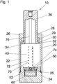
- Fig. 1 shows a longitudinal section through an embodiment of a gas spring 10, which has a housing 20 and a displaceably arranged in the housing 20 piston 30.
- the housing 20 is cylindrical, in particular circular-cylindrical, and has a wall 22, a bottom part 24 and a cover part 26.
- the cover part 26 is in particular integrally connected to the wall 22, while the bottom part 24 is advantageously arranged detachably on the wall 22 and, for example, by means of a screw connection to the wall 22 is connectable.
- the piston 30 is cylindrical with an outer surface 32 and an end face 34 and a piston rod 36.
- the cover part 26 of the housing 20 has an opening 28 through which the piston rod 36 is guided out of the housing 20 to the outside.
- the housing 20 has a longitudinal axis 1 along which the piston 30 is slidably disposed in the housing 20.
- a gas compression chamber 40 is formed between the piston 30 and the housing 20, a gas compression chamber 40 is formed.
- the gas compression chamber is sealed in the opening 28, through which the piston rod 36 is led out of the housing 20 to the outside, by a seal 29.
- gas from a first part of the gas compression chamber 40, which is disposed between the end face 34 of the piston 30 and the bottom part 24 of the housing 20, into a second part of the gas compression chamber 40, which between the piston 30 and the cover part 26 is formed stream. In this way, a so-called two-chamber gas compression chamber 40 is formed.
- the gas pressure spring 10 may also be a gas pressure spring with a single-chamber gas compression chamber 40.
- a single-chamber gas compression chamber 40 the piston 30 is sealed at its outer surface 32 via a seal against the wall 22 of the housing 20, so that a gas flow from the area between the end face 34 of the piston 30 and the bottom part 24 of the housing 20 in the area between the piston 30 and the lid part 26 is prevented.
- a seal in the opening 28, through which the piston rod 36 is guided out of the housing 20, can then be omitted.
- a gas for example nitrogen
- a gas for example nitrogen
- the gas spring 10 has a sensor 50 for detecting a physical quantity.
- the sensor 50 may be formed as a pressure sensor, temperature sensor, force sensor or displacement sensor.
- the sensor 50 may be formed as a combined pressure and temperature sensor.
- the sensor 50 is integrated, for example, in the bottom part 24 such that it can detect physical variables, for example pressure and / or temperature, in the gas compression chamber 40.
- the detected by the sensor 50 sizes can be further processed by an arranged in a cavity 25 of the bottom part 24 electronics 52, for example, stored and evaluated.
- the gas pressure spring 10 has means 70, which are designed to generate at least part of the energy required for the power supply of the sensor 50.
- the means 70 comprise a coil 72 and a magnet 76.
- the magnet 76 is arranged on the piston 30, while the coil 72 is arranged on the housing 20, in particular in the gas compression chamber 40.
- the coil 72 is arranged such that its longitudinal axis is parallel to the longitudinal axis L of the gas spring 10.
- the magnet 76 is arranged on the piston 30 such that upon relative movement between the piston 30 and the housing 20, the magnet 76 can dip into the coil 72.
- the coil 72 has connection contacts 74 which are led out of the gas compression chamber 40 in a pressure-tight manner and in particular are guided into the cavity 25 of the bottom part 24.
- the terminals 74 connect the coil 72 to either the sensor 50 or the electronics 52.
- a voltage is induced in the coil 72, which can serve to generate electrical energy, which can serve to power the sensor 50 and an optionally existing electronics 52.
- the power supply of the sensor 50 and the electronics 52 is completely realized by the energy generated by the means 70. If the energy generated by the means 70 should not be sufficient, the gas spring 10 may additionally comprise a battery 60.
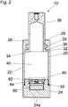
- Fig. 2 shows a longitudinal section through a further embodiment of a gas spring 10 ', which differs from the in Fig. 1 illustrated gas spring 10 only in the embodiment of the means for generating at least a portion of the power supply to the sensor 50 necessary energy differs.
- the gas spring 10 ' has means 80 which are adapted to generate electrical energy from the pressure change in the gas spring 10', in particular from the pressure change in the gas compression chamber 40.
- the means 80 a piezoelectric element 82, which in the in Fig. 2 illustrated embodiment in the gas compression chamber 40, in particular on the bottom part 24, is arranged.
- Terminal contacts 84 of the piezoelectric element 82 are pressure-tight out of the gas compression chamber 40, in particular in the cavity 25 of the bottom part 24, where they connect the piezoelectric element 82 with the sensor 50 or a possibly.
- Existing electronics 52 In a pressure change electrical energy is generated in a piezoelectric element, which can serve to power the sensor 50 or the electronics 52.
- the piezoelectric element 82 may also be on an outer bottom side 24a of the bottom part 24 are arranged.
- the electrical contact between this piezoelectric element 82 and the cavity 25 of the bottom part 24 could be made by a not necessarily pressure-tight opening, which leads from the outer bottom side 24 a to the cavity 25.
- Such arranged piezoelectric element 82 would be directly accessible and easily replaceable and could also act as a force sensor, would detect the pressure prevailing in the gas compression chamber 40 but less directly.
- Fig. 3 shows a further embodiment of a gas pressure spring 10 "according to the invention, which differs from the in Fig. 1 illustrated gas spring 10 only by the configuration of the means for generating at least a portion of the power supply to the sensor 50 necessary energy differs.
- the gas pressure spring 10 has means 90, which are designed to generate electrical energy from the thermal energy radiated in the gas pressure spring,
- the means 90 comprise, in particular, a Peltier element 92 with a first side 94 and a second side 96 , 96 of a Peltier element 92 represent in particular the hot and the cold side of the Peltier element 92.
- the Peltier element 92 is in particular arranged in the housing 20 in such a way that the first side 94 is in heat-conducting contact with the housing 20 and the second side 96 is in heat-conducting contact with the surroundings of the gas pressure spring 10 "The second side 96 of the Peltier element 92 thus forms in particular a part of the outer surface of the gas spring 10 ".
- the Peltier element 92 is arranged in the bottom part 24, for example such that the second side 96 lies in the outer bottom side 24 a of the bottom part 24.
- the Peltier element 92 is connected via terminals 98 to the sensor 50 the electronics 52 connected.
- the first side 94 of the Peltier element 52 absorbs the heat generated in the housing 20, while the heat is dissipated via the second side 96 to the environment of the gas spring 10 ", for example to the tool or a machine, wherein in the Peltier element 92 generates a voltage is, which can serve to power the sensor 50 and, if necessary, the electronics 52.
Landscapes
- Engineering & Computer Science (AREA)
- General Engineering & Computer Science (AREA)
- Mechanical Engineering (AREA)
- Measuring Fluid Pressure (AREA)
- Fluid-Damping Devices (AREA)
Description
- Die Erfindung betrifft eine Gasdruckfeder gemäß dem Oberbegriff des Patentanspruchs 1.
- Gasdruckfedern weisen üblicherweise ein zylindrisches Gehäuse mit einer Wandung, einem Bodenteil und einem eine Öffnung aufweisenden Deckelteil sowie einer Längsachse auf, wobei in dem Gehäuse entlang der Längsachse ein Kolben mit einer Außenfläche, einer Stirnseite und einer durch die Öffnung geführten Kolbenstange verschiebbar angeordnet ist. Zwischen der Stirnseite des Kolbens und dem Bodenteil des Gehäuses ist eine Gaskompressionskammer gebildet. Derartige Gasdruckfedern werden insbesondere in Werkzeugen oder Maschinen eingesetzt, um Hubbewegungen durchzuführen.
- Ein häufig verwendetes Gas zur Befüllung der Gasdruckfedern ist Stickstoff. Gasdruckfedern sind mit Stickstoff oft bei Drucken zwischen 120 und 220 bar gefüllt. Zur Sicherheitsüberwachung ist es beispielsweise aus der
DE 10 2007 034 416 A1 bekannt, Gasdruckfedern mit einem Sensor zur Überwachung von physikalischen Messgrößen innerhalb und/oder an der Gasdruckfeder auszustatten. Zur Stromversorgung des Sensors kann entweder ein Kabel vorgesehen werden, was jedoch ein Verkabelungsaufwand erfordert. Alternativ kann bei den Gasdruckfedern gemäß derDE 10 2007 034 416 A1 die Stromversorgung auch netzunabhängig durch Batterien, Akkumulatoren oder induktiv bewerkstelligt werden. - Batterien und Akkumulatoren haben jedoch nur eine begrenzte Lebensdauer, welche oft kürzer als die Lebensdauer der Gasdruckfeder ist. Eine induktive Stromversorgung ist bei in Werkzeugen oder Maschinen eingebauten Gasdruckfedern schwierig zu realisieren.
- Aus
DE 10 2005 046 745 A1 sind auch Druckmittelzylinder mit einem Druckaufnehmer bekannt, wobei der Druckaufnehmer einen Piezokristall als Drucksensor aufweist, der zusätzlich als Energieversorgung für eine Auswerteeinheit agieren kann. - Die Aufgabe der Erfindung besteht daher darin, eine Gasdruckfeder bereitzustellen, bei welcher die Stromversorgung des Sensors zur Detektion einer physikalischen Größe weitergebildet wird, insbesondere derart, dass eine netzunabhängige Stromversorgung bereitgestellt wird, ohne die Lebensdauer der Gasdruckfeder zu beeinträchtigen.
- Die Aufgabe wird erfindungsgemäß gelöst durch eine Gasdruckfeder mit den Merkmalen des Patentanspruchs 1.
- Vorteilhafte Ausgestaltungen und Weiterbildungen der Erfindung sind in den abhängigen Ansprüchen angegeben.
- Die erfindungsgemäße Gasdruckfeder mit einem zylindrischen Gehäuse, welches eine Wandung, ein Bodenteil und ein eine Öffnung aufweisendes Deckelteil sowie eine Längsachse aufweist, und mit einem in dem Gehäuse entlang der Längsachse verschiebbaren Kolben mit einer Außenfläche und einer Stirnseite, wobei zwischen dem Kolben und dem Gehäuse eine Gaskompressionskammer gebildet ist und wobei die Gasdruckfeder wenigstens einen Sensor zur Detektion einer physikalischen Größe aufweist, zeichnet sich dadurch aus, dass die Gasdruckfeder Mittel aufweist, welche zur Erzeugung zumindest eines Teils der zur Stromversorgung des wenigstens einen Sensors nötigen elektrischen Energie ausgebildet sind. Dadurch, dass innerhalb der Gasdruckfeder selbst Energie erzeugt wird, ist die Gasdruckfeder weniger, vorteilhafterweise gar nicht, auf die Zufuhr von Energie von außerhalb oder auf die Zufuhr von Energie mittels Batterien oder Akkumulatoren angewiesen. Externe Verkabelungen können vollständig entfallen. Weiterhin wird die Lebensdauer der Gasdruckfeder nicht mehr durch die Lebensdauer der Batterie oder des Akkumulators begrenzt.
- In einer Ausführungsform ist die Gaskompressionskammer zwischen der Stirnseite des Kolbens und dem Bodenteil des Gehäuses gebildet, wobei die Außenfläche des Kolbens gegen die Wandung des Gehäuses abgedichtet ist, so dass eine sogenannte Ein-Kammer-Gaskompressionskammer gebildet wird. In einer alternativen Ausführungsform weist die Gaskompressionskammer zwei Kammern auf, wobei eine erste Kammer zwischen dem Kolben und dem Deckelteil und eine zweite Kammer zwischen der Stirnseite des Kolbens und dem Bodenteil des Gehäuses gebildet ist, so dass eine sogenannte Zwei-Kammer-Gaskompressionskammer gebildet wird. Bei einer Zwei-Kammer-Gaskompressionskammer ist ein Gasfluss von dem Bereich zwischen dem Kolben und dem Deckelteil zu dem Bereich zwischen dem Kolben und dem Bodenteil zwischen der Außenfläche des Kolbens und der Wandung des Gehäuses möglich, während eine Abdichtung der Gaskompressionskammer zwischen der Kolbenstange und dem Gehäuse in der Öffnung des Deckelteils erfolgt.
- Eine vorteilhafte Ausgestaltung der Erfindung sieht vor, dass die Mittel zur Erzeugung elektrischer Energie aus der Relativbewegung zwischen dem Kolben und dem Gehäuse ausgebildet sind. Da in der Gasdruckfeder zwei regelmäßig, oft mit großer Geschwindigkeit, gegeneinander bewegte Komponenten vorhanden sind, nämlich das Gehäuse und der Kolben, kann auf einfache Art und Weise die kinetische Energie durch die Mittel in elektrische Energie umgesetzt werden.
- Vorteilhafterweise weisen die Mittel eine Spule und einen Magneten auf, da bei Relativbewegung zwischen einer Spule und einem Magneten in der Spule eine Spannung induziert werden kann, welche in einfacher Art und Weise zur Stromversorgung des Sensors verwendet werden kann.
- Eine bevorzugte Ausführungsform der Erfindung sieht vor, dass der Magnet an dem Kolben und die Spule an dem Gehäuse, vorzugsweise innerhalb der Gaskompressionskammer, angeordnet sind, da durch eine relativ zum Gehäuse feststehende Spule der Anschluss der Spule an den Sensor oder eine Elektronik vereinfacht werden kann.
- Besonders bevorzugt weist die Spule Anschlusskontakte auf, welche druckdicht aus der Gaskompressionskammer herausgeführt sind, vorzugsweise in das Bodenteil. Das druckdichte Herausführen der Anschlusskontakte der Spule gewährleistet die Dichtigkeit der Gaskompressionskammer. Das Herausführen der Anschlusskontakte in das Bodenteil ist dann von Vorteil, wenn der Sensor und ggfs. eine zugehörige Elektronik in dem Bodenteil angeordnet sind, so dass lediglich kurze Wege innerhalb der Gasdruckfeder zurückzulegen sind.
- Eine weitere vorteilhafte Ausführungsform der Erfindung sieht vor, dass die Mittel ausgebildet sind, elektrische Energie aus der Druckänderung in der Gasdruckfeder, insbesondere in der Gaskompressionskammer, zu erzeugen. Da in einer Gasdruckfeder durch die regelmäßige Relativbewegung zwischen dem Kolben und dem Gehäuse regelmäßig starke Druckänderungen auftreten, kann auch auf diese Weise regelmäßig bei jedem Hub der Gasdruckfeder Energie erzeugt werden.
- Vorteilhafterweise weisen die Mitteil ein Piezoelement auf, welches insbesondere auf der Außenseite des Bodenteils oder in der Gaskompressionskammer angeordnet ist. Die Anordnung des Piezoelements auf der Außenseite des Bodenteils weist den Vorteil auf, dass ein Herausführen von Anschlusskontakten des Piezoelements aus der Gaskompressionskammer entfallen kann. Andererseits wird jedoch der Druck nicht so unmittelbar wie bei Anordnung des Piezoelements innerhalb der Gaskompressionskammer ermittelt.
- Vorteilhafterweise weist das Piezoelement, welches in der Gaskompressionskammer angeordnet ist, Anschlusskontakte auf, welche druckdicht aus der Gaskompressionskammer herausgeführt sind, vorzugsweise in das Bodenteil. Durch die druckdichte Herausführung wird einerseits die Dichtigkeit der Gaskompressionskammer nicht beeinträchtigt. Bei Herausführen der Anschlusskontakte in das Bodenteil, in welchem beispielsweise der Sensor und ggfs. eine Elektronik angeordnet ist, sind lediglich kurze Wege innerhalb der Gasdruckfeder zu überbrücken.
- Ein weiteres vorteilhaftes Ausführungsbeispiel der Erfindung sieht vor, dass die Mittel ausgebildet sind, elektrische Energie aus der in Gasdruckfeder abgestrahlten Wärmeenergie zu erzeugen. Da sich durch die Kompression des Gasvolumens in der Gasdruckfeder das Gas um 10 bis 20 K erwärmen kann, kann auf diese Art und Weise auch die entstandene Wärme zur Erzeugung von elektrischer Energie genutzt werden.
- Vorteilhafterweise weisen die Mittel ein Peltier-Element mit einer ersten Seite und einer zweiten Seite auf, welches vorzugsweise in dem Gehäuse, insbesondere dem Bodenteil, derart angeordnet ist, dass die erste Seite in wärmeleitendem Kontakt mit dem Gehäuse und die zweite Seite in wärmeleitendem Kontakt mit der Umgebung der Gasdruckfeder ist. Die erste Seite nimmt somit die Wärme aus dem durch den Temperaturanstieg des Gases aufgewärmten Gehäuse auf, während die zweite Seite die Wärme an die Umgebung, beispielsweise an ein Werkzeug oder eine Maschine, in welchem die Gasdruckfeder angeordnet ist, abführen kann.
- Die Erfindung wird anhand der nachfolgenden Figuren ausführlich erläutert.
- Es zeigen:
- Fig. 1
- einen Längsschnitt durch ein erstes Ausführungsbeispiel einer erfindungsgemäßen Gasdruckfeder,
- Fig. 2
- einen Längsschnitt durch ein zweites Ausführungsbeispiel einer erfindungsgemäßen Gasdruckfeder und
- Fig. 3
- einen Längsschnitt durch ein drittes Ausführungsbeispiel einer erfindungsgemäßen Gasdruckfeder.
-
Fig. 1 zeigt einen Längsschnitt durch ein Ausführungsbeispiel einer Gasdruckfeder 10, welcher ein Gehäuse 20 und einen in dem Gehäuse 20 verschiebbar angeordneten Kolben 30 aufweist. Das Gehäuse 20 ist zylindrisch, insbesondere kreiszylindrisch, ausgebildet und weist eine Wandung 22, ein Bodenteil 24 und ein Deckelteil 26 auf. Das Deckelteil 26 ist insbesondere einstückig mit der Wandung 22 verbunden, während das Bodenteil 24 vorteilhafterweise lösbar an der Wandung 22 angeordnet ist und beispielsweise mittels einer Schraubverbindung mit der Wandung 22 verbindbar ist. - Der Kolben 30 ist zylindrisch ausgebildet mit einer Außenfläche 32 sowie einer Stirnseite 34 und einer Kolbenstange 36. Das Deckelteil 26 des Gehäuses 20 weist eine Öffnung 28 auf, durch welche die Kolbenstange 36 aus dem Gehäuse 20 nach außen geführt ist.
- Das Gehäuse 20 weist eine Längsachse 1 auf, entlang welcher der Kolben 30 in dem Gehäuse 20 verschiebbar angeordnet ist.
- Zwischen dem Kolben 30 und dem Gehäuse 20 ist eine Gaskompressionskammer 40 gebildet. Die Gaskompressionskammer ist in der Öffnung 28, durch welche die Kolbenstange 36 aus dem Gehäuse 20 nach außen geführt ist, durch eine Dichtung 29 abgedichtet. An der Außenfläche des Kolbens 30 kann Gas von einem ersten Teil der Gaskompressionskammer 40, welcher zwischen der Stirnseite 34 des Kolbens 30 und dem Bodenteil 24 des Gehäuses 20 angeordnet ist, in einen zweiten Teil der Gaskompressionskammer 40, welcher zwischen dem Kolben 30 und dem Deckelteil 26 gebildet ist, strömen. Auf diese Weise wird eine sogenannte Zwei-Kammer-Gaskompressionskammer 40 gebildet.
- In einer alternativen, nicht dargestellten Ausführungsform kann es sich bei der Gasdruckfeder 10 auch um eine gasdruckfeder mit einer Ein-Kammer-Gaskompressionskammer 40 handelt. Bei einer Ein-Kammer-Gaskompressionskammer 40 ist der Kolben 30 an seiner Außenfläche 32 über eine Dichtung gegenüber der Wandung 22 des Gehäuses 20 abgedichtet, so dass ein Gasfluss von dem Bereich zwischen der Stirnseite 34 des Kolbens 30 und dem Bodenteil 24 des Gehäuses 20 in den Bereich zwischen dem Kolben 30 und dem Deckelteil 26 unterbunden wird. Eine Dichtung in der Öffnung 28, durch welche die Kolbenstange 36 aus dem Gehäuse 20 geführt wird, kann dann entfallen.
- In der Gasdruckfeder 10, insbesondere der Gaskompressionskammer 40, ist ein Gas, beispielsweise Stickstoff, angeordnet, welches bei Einführen des Kolbens 30 in das Gehäuse 20 verdichtet wird, so dass sich ein Druck aufbaut. Dieser erzeugt eine Rückstellkraft auf den Kolben 30. Derartige Gasdruckfedern 10 werden insbesondere in Werkzeugen oder Maschinen eingesetzt.
- Die Gasdruckfeder 10 weist einen Sensor 50 zur Detektion einer physikalischen Größe auf. Beispielsweise kann der Sensor 50 als Drucksensor, Temperatursensor, Kraftsensor oder Wegsensor ausgebildet sein. In einer bevorzugten Ausführungsform kann der Sensor 50 als kombinierter Druck- und Temperatursensor ausgebildet sein. Der Sensor 50 ist beispielsweise in das Bodenteil 24 derart integriert, dass er physikalische Größen, beispielsweise Druck und/oder Temperatur, in der Gaskompressionskammer 40 detektieren kann. Die von dem Sensor 50 detektierten Größen können von einer in einem Hohlraum 25 des Bodenteils 24 angeordneten Elektronik 52 weiterverarbeitet, beispielsweise gespeichert und ausgewertet werden.
- Der Sensor 50 und eine ggfs. vorhandene Elektronik 52 benötigen zum Betrieb elektrische Energie. Die Gasdruckfeder 10 weist Mittel 70 auf, welche zur Erzeugung zumindest eines Teils der zur Energieversorgung des Sensors 50 nötigen Energie ausgebildet sind. Die Mittel 70 weisen eine Spule 72 und einen Magneten 76 auf. Der Magnet 76 ist an dem Kolben 30 angeordnet, während die Spule 72 an dem Gehäuse 20, insbesondere in der Gaskompressionskammer 40, angeordnet ist. Die Spule 72 ist dabei derart angeordnet, dass ihre Längsachse parallel zur Längsachse L der Gasdruckfeder 10 verläuft. Der Magnet 76 ist derart an dem Kolben 30 angeordnet, dass bei einer Relativbewegung zwischen dem Kolben 30 und dem Gehäuse 20 der Magnet 76 in die Spule 72 eintauchen kann. Die Spule 72 weist Anschlusskontakte 74 auf, welche druckdicht aus der Gaskompressionskammer 40 herausgeführt und insbesondere in den Hohlraum 25 des Bodenteils 24 hineingeführt sind. Insbesondere verbinden die Anschlusskontakte 74 die Spule 72 mit entweder dem Sensor 50 oder der Elektronik 52. Durch die Relativbewegung des Magneten 76 und der Spule 72 wird in der Spule 72 eine Spannung induziert, welche zur Erzeugung von elektrischer Energie dienen kann, die zur Stromversorgung des Sensors 50 und einer ggfs. vorhandenen Elektronik 52 dienen kann. Vorteilhafterweise wird die Stromversorgung des Sensors 50 und der Elektronik 52 vollständig durch die durch die Mittel 70 erzeugte Energie realisiert. Falls die durch die Mittel 70 erzeugte Energie nicht ausreichend sein sollte, kann die Gasdruckfeder 10 zusätzlich eine Batterie 60 aufweisen.
-
Fig. 2 zeigt einen Längsschnitt durch ein weiteres Ausführungsbeispiel einer Gasdruckfeder 10', welche sich von der inFig. 1 dargestellten Gasdruckfeder 10 lediglich in der Ausgestaltung der Mittel zur Erzeugung zumindest eines Teils der zur Energieversorgung des Sensors 50 nötigen Energie unterscheidet. Die Gasdruckfeder 10' weist Mittel 80 auf, welche ausgebildet sind, aus der Druckänderung in der Gasdruckfeder 10', insbesondere aus der Druckänderung in der Gaskompressionskammer 40, elektrische Energie zu erzeugen. Dazu weisen die Mittel 80 ein Piezoelement 82 auf, welches in dem inFig. 2 dargestellten Ausführungsbeispiel in der Gaskompressionskammer 40, insbesondere an dem Bodenteil 24, angeordnet ist. Anschlusskontakte 84 des Piezoelements 82 sind druckdicht aus der Gaskompressionskammer 40 herausgeführt, insbesondere in den Hohlraum 25 des Bodenteils 24, wo sie das Piezoelement 82 mit dem Sensor 50 oder einer ggfs. vorhandenen Elektronik 52 verbinden. Bei einer Druckänderung wird in einem Piezoelement elektrische Energie erzeugt, die zur Stromversorgung des Sensors 50 oder der Elektronik 52 dienen kann. - In einer alternativen, nicht dargestellten Ausführungsform der Erfindung kann das Piezoelement 82 auch an einer äußeren Bodenseite 24a des Bodenteils 24 angeordnet werden. Der elektrische Kontakt zwischen diesem Piezoelement 82 und dem Hohlraum 25 des Bodenteils 24 könnte durch eine nicht notwendigerweise druckdicht ausgebildete Öffnung, welche von der äußeren bodenseite 24a zu dem Hohlraum 25 führt, erfolgen. Ein derart angeordnetes Piezoelement 82 wäre direkt zugänglich und einfach austauschbar und könnte zudem auch als Kraftsensor fungieren, würde den in der Gaskompressionskammer 40 herrschenden Druck jedoch weniger unmittelbar detektieren.
-
Fig. 3 zeigt ein weiteres Ausführungsbeispiel einer erfindungsgemäßen Gasdruckfeder 10", welche sich von der inFig. 1 dargestellten Gasdruckfeder 10 lediglich durch die Ausgestaltung der Mittel zur Erzeugung zumindest eines Teils der zur Energieversorgung des Sensors 50 nötigen Energie unterscheidet. Die Gasdruckfeder 10" weist Mittel 90 auf, welche zur Erzeugung elektrischer Energie aus der in der Gasdruckfeder abgestrahlten Wärmeenergie ausgebildet sind. Die Mittel 90 weisen insbesondere ein Peltier-Element 92 mit einer ersten Seite 94 und einer zweiten Seite 96 auf. Die beiden Seiten 94, 96 eines Peltier-Elements 92 stellen insbesondere die warme und die kalte Seite des Peltierelements 92 dar. - Das Peltierelement 92 ist insbesondere derart in dem Gehäuse 20 angeordnet, dass die erste Seite 94 in wärmeleitendem Kontakt mit dem Gehäuse 20 und die zweite Seite 96 in wärmeleitendem Kontakt mit der Umgebung der Gasdruckfeder 10" ist. Die zweite Seite 96 des Peltierelements 92 bildet somit insbesondere einen Teil der Außenfläche der Gasdruckfeder 10". Insbesondere ist das Peltierelement 92 in dem Bodenteil 24 angeordnet, beispielsweise derart, dass die zweite Seite 96 in der äußeren Bodenseite 24a des Bodenteils 24 liegt. Das Peltierelement 92 ist über Anschlusskontakte 98 mit dem Sensor 50 der der Elektronik 52 verbunden. Die erste Seite 94 des Peltierelements 52 nimmt die in dem Gehäuse 20 erzeugte Wärme auf, während die Wärme über die zweite Seite 96 an die Umgebung der Gasdruckfeder 10" beispielsweise an das Werkzeug oder eine Maschine abgeführt wird, wobei in dem Peltierelement 92 eine Spannung erzeugt wird, die zur Stromversorgung des Sensors 50 und ggfs. der Elektronik 52 dienen kann.
-
- 10
- Gasdruckfeder
- 10'
- Gasdruckfeder
- 10"
- Gasdruckfeder
- 20
- Gehäuse
- 22
- Wandung
- 24
- Bodenteil
- 24a
- Bodenseite
- 25
- Hohlraum
- 26
- Deckelteil
- 28
- Öffnung
- 29
- Dichtung
- 30
- Kolben
- 32
- Außenfläche
- 34
- Stirnseite
- 36
- Kolbenstange
- 40
- Gaskompressionskammer
- 50
- Sensor
- 52
- Elektronik
- 60
- Batterie
- 70
- Mittel
- 72
- Spule
- 74
- Anschlusskontakt
- 76
- Magnet
- 80
- Mittel
- 82
- Piezoelement
- 84
- Anschlusskontakt
- 90
- Mittel
- 92
- Peltierelement
- 94
- erste Seite
- 96
- zweite Seite
- 98
- Anschlusskontakt
- 1
- Längsachse
Claims (10)
- Gasdruckfeder (10, 10', 10") mit einem zylindrischen Gehäuse (20), welches eine Wandung (22), ein Bodenteil (24) und ein eine Öffnung (28) aufweisendes Deckelteil (26) sowie eine Längsachse (1) aufweist, und mit einem in dem Gehäuse (20) entlang der Längsachse (1) verschiebbaren Kolben (30) mit einer Außenfläche (32) und einer Stirnseite (34), wobei zwischen dem Kolben (30) und dem Gehäuse (20) eine Gaskompressionskammer (40) gebildet ist und wobei die Gasdruckfeder (10, 10', 10") wenigstens einen Sensor (50) zur Detektion wenigstens einer physikalischen Größe aufweist,
dadurch gekennzeichnet, dass die Gasdruckfeder (10, 10', 10") Mittel (70, 80, 90) zur Erzeugung zumindest eines Teils der zur Stromversorgung des wenigstens einen Sensors (50) nötigen elektrischen Energie aufweist. - Gasdruckfeder nach Anspruch 1,
dadurch gekennzeichnet, dass die Mittel (70) zur Erzeugung elektrischer Energie aus der Relativbewegung zwischen dem Kolben (30) und dem Gehäuse (20) ausgebildet sind. - Gasdruckfeder nach Anspruch 2,
dadurch gekennzeichnet, dass die Mittel (70) eine Spule (72) und einen Magneten (76) aufweisen. - Gasdruckfeder nach Anspruch 3,
dadurch gekennzeichnet, dass der Magnet (76) an dem Kolben (30) und die Spule (72) an dem Gehäuse (20), vorzugsweise innerhalb der Gaskompressionskammer (40), angeordnet sind. - Gasdruckfeder nach Anspruch 4,
dadurch gekennzeichnet, dass die Spule (72) Anschlusskontakte (74) aufweist, welche druckdicht aus der Gaskompressionskammer (40) herausgeführt sind, vorzugsweise in das Bodenteil (24). - Gasdruckfeder nach einem der vorhergehenden Ansprüche,
dadurch gekennzeichnet, dass die Mittel (80) zur Erzeugung elektrischer Energie aus der Druckänderung in der Gasdruckfeder (10'), insbesondere in der Gaskompressionskammer (40), ausgebildet sind. - Gasdruckfeder nach Anspruch 6,
dadurch gekennzeichnet, dass die Mittel (80) ein Piezoelement (82) aufweisen, welches vorzugsweise auf der Außenseite des Bodenteils (24) oder in der Gaskompressionskammer (40) angeordnet ist. - Gasdruckfeder nach Anspruch 7,
dadurch gekennzeichnet, dass das Piezoelement (82) in der Gaskompressionskammer (40) angeordnet ist und Anschlusskontakte (84) aufweist, welche druckdicht aus der Gaskompressionskammer (40) herausgeführt sind, vorzugsweise in das Bodenteil (24). - Gasdruckfeder nach einem der vorhergehenden Ansprüche,
dadurch gekennzeichnet, dass die Mittel (90) zur Erzeugung elektrischer Energie aus der in der Gasdruckfeder (10") abgestrahlten Wärmeenergie ausgebildet sind. - Gasdruckfeder nach Anspruch 9,
dadurch gekennzeichnet, dass die Mittel (90) ein Peltier-Element (92) mit einer ersten Seite (94) und einer zweiten Seite (96) aufweisen, welches vorzugsweise in dem Gehäuse (20), insbesondere dem Bodenteil (24), derart angeordnet ist, dass die erste Seite (94) in wärmeleitendem Kontakt mit dem Gehäuse (20) und die zweite Seite (96) in wärmeleitendem Kontakt mit der Umgebung der Gasdruckfeder (10") ist.
Applications Claiming Priority (1)
| Application Number | Priority Date | Filing Date | Title |
|---|---|---|---|
| DE102014104482.7A DE102014104482A1 (de) | 2014-03-31 | 2014-03-31 | Gasdruckfeder |
Publications (3)
| Publication Number | Publication Date |
|---|---|
| EP2937595A2 EP2937595A2 (de) | 2015-10-28 |
| EP2937595A3 EP2937595A3 (de) | 2015-12-30 |
| EP2937595B1 true EP2937595B1 (de) | 2018-05-02 |
Family
ID=52874949
Family Applications (1)
| Application Number | Title | Priority Date | Filing Date |
|---|---|---|---|
| EP15161830.3A Active EP2937595B1 (de) | 2014-03-31 | 2015-03-31 | Gasdruckfeder |
Country Status (4)
| Country | Link |
|---|---|
| EP (1) | EP2937595B1 (de) |
| DE (1) | DE102014104482A1 (de) |
| DK (1) | DK2937595T3 (de) |
| ES (1) | ES2677651T3 (de) |
Cited By (1)
| Publication number | Priority date | Publication date | Assignee | Title |
|---|---|---|---|---|
| US11592499B2 (en) | 2019-12-10 | 2023-02-28 | Barnes Group Inc. | Wireless sensor with beacon technology |
Families Citing this family (1)
| Publication number | Priority date | Publication date | Assignee | Title |
|---|---|---|---|---|
| CN114739562A (zh) * | 2021-01-07 | 2022-07-12 | 配天机器人技术有限公司 | 一种工业机器人用氮气弹簧压力监测系统及工业机器人 |
Citations (9)
| Publication number | Priority date | Publication date | Assignee | Title |
|---|---|---|---|---|
| DE4421773A1 (de) | 1994-06-22 | 1995-10-05 | Fichtel & Sachs Ag | Gasfeder |
| DE102004034706B3 (de) | 2004-07-17 | 2006-02-23 | Stabilus Gmbh | Fluidfeder |
| DE102005048745A1 (de) | 2005-10-10 | 2007-04-12 | Ludwig Ehrhardt Gmbh | Druckmittelzylinder sowie Verfahren zum Erfassen der Betriebszeit und/oder Betriebszyklen eines Druckmittelzylinders |
| DE102007034416A1 (de) | 2007-07-20 | 2009-01-22 | Läpple AG | Gasdruckfeder mit Messmittel sowie Einrichtung und Verfahren zur Überwachung zumindest einer innerhalb und/oder an einer Gasdruckfeder auftretenden physikalischen Messgröße |
| DE102009032897A1 (de) | 2009-07-10 | 2011-01-27 | Stabilus Gmbh | Kolben-Zylinderaggregat |
| DE102009040198A1 (de) | 2009-09-07 | 2011-03-10 | Karlsruher Institut für Technologie | Radar Sensorik zur Überwachung von Flüssigkeitsansammlungen im menschlichen Körper |
| US20110084503A1 (en) | 2009-10-14 | 2011-04-14 | Gm Global Technology Operations, Inc. | Self-powered vehicle sensor systems |
| DE102010020600A1 (de) | 2010-05-14 | 2011-11-17 | SMARTEC IngenieurBüro GbR (vertretungsberechtigter Gesellschafter Herr Ulrich Schubert, Kopferspitz 19, 82152 Planegg) | Schwingungsdämpfer und Dämpfungsbaugruppe |
| DE202007019504U1 (de) | 2007-07-20 | 2013-03-13 | Fibro Gmbh | Gasdruckfeder mit Messmittel sowie Einrichtung zur Überwachung zumindest einer innerhalb und/oder an einer Gasruckfeder auftretenden physikalischen Messgröße |
Family Cites Families (1)
| Publication number | Priority date | Publication date | Assignee | Title |
|---|---|---|---|---|
| DE202012003867U1 (de) * | 2012-04-18 | 2012-05-25 | Steinel Normalien Ag | Gasdruckfeder |
-
2014
- 2014-03-31 DE DE102014104482.7A patent/DE102014104482A1/de active Pending
-
2015
- 2015-03-31 ES ES15161830.3T patent/ES2677651T3/es active Active
- 2015-03-31 EP EP15161830.3A patent/EP2937595B1/de active Active
- 2015-03-31 DK DK15161830.3T patent/DK2937595T3/da active
Patent Citations (9)
| Publication number | Priority date | Publication date | Assignee | Title |
|---|---|---|---|---|
| DE4421773A1 (de) | 1994-06-22 | 1995-10-05 | Fichtel & Sachs Ag | Gasfeder |
| DE102004034706B3 (de) | 2004-07-17 | 2006-02-23 | Stabilus Gmbh | Fluidfeder |
| DE102005048745A1 (de) | 2005-10-10 | 2007-04-12 | Ludwig Ehrhardt Gmbh | Druckmittelzylinder sowie Verfahren zum Erfassen der Betriebszeit und/oder Betriebszyklen eines Druckmittelzylinders |
| DE102007034416A1 (de) | 2007-07-20 | 2009-01-22 | Läpple AG | Gasdruckfeder mit Messmittel sowie Einrichtung und Verfahren zur Überwachung zumindest einer innerhalb und/oder an einer Gasdruckfeder auftretenden physikalischen Messgröße |
| DE202007019504U1 (de) | 2007-07-20 | 2013-03-13 | Fibro Gmbh | Gasdruckfeder mit Messmittel sowie Einrichtung zur Überwachung zumindest einer innerhalb und/oder an einer Gasruckfeder auftretenden physikalischen Messgröße |
| DE102009032897A1 (de) | 2009-07-10 | 2011-01-27 | Stabilus Gmbh | Kolben-Zylinderaggregat |
| DE102009040198A1 (de) | 2009-09-07 | 2011-03-10 | Karlsruher Institut für Technologie | Radar Sensorik zur Überwachung von Flüssigkeitsansammlungen im menschlichen Körper |
| US20110084503A1 (en) | 2009-10-14 | 2011-04-14 | Gm Global Technology Operations, Inc. | Self-powered vehicle sensor systems |
| DE102010020600A1 (de) | 2010-05-14 | 2011-11-17 | SMARTEC IngenieurBüro GbR (vertretungsberechtigter Gesellschafter Herr Ulrich Schubert, Kopferspitz 19, 82152 Planegg) | Schwingungsdämpfer und Dämpfungsbaugruppe |
Non-Patent Citations (3)
| Title |
|---|
| BENJAMIN BENZ: "Batterie? Nein danke!", C'T, 23 February 2013 (2013-02-23), pages 160 - 165, XP055557132 |
| JÖRG WALLASCHEK: "Energy Harvesting: Grundlagen und Praxis energieautarker Systeme", 20 November 2007 (2007-11-20), XP055557126 |
| NECHIBVUTE ET AL.: "Piezoelectric Energy Harvesting Devices: An Alternative Energy Source for Wireless Sensors", SMART MATERIALS RESEARCH, vol. 2012, 2012, pages 1 - 13, XP055557112 |
Cited By (1)
| Publication number | Priority date | Publication date | Assignee | Title |
|---|---|---|---|---|
| US11592499B2 (en) | 2019-12-10 | 2023-02-28 | Barnes Group Inc. | Wireless sensor with beacon technology |
Also Published As
| Publication number | Publication date |
|---|---|
| ES2677651T3 (es) | 2018-08-06 |
| DE102014104482A1 (de) | 2015-10-01 |
| DK2937595T3 (da) | 2018-07-23 |
| EP2937595A3 (de) | 2015-12-30 |
| EP2937595A2 (de) | 2015-10-28 |
Similar Documents
| Publication | Publication Date | Title |
|---|---|---|
| DE102009032897B4 (de) | Kolben-Zylinderaggregat | |
| EP3270117B1 (de) | Datenlogger | |
| DE202014101509U1 (de) | Gasdruckfeder | |
| EP2937595B1 (de) | Gasdruckfeder | |
| DE102015116324A1 (de) | Schraubenverdichter | |
| DE102016109103A1 (de) | Elektrohydraulischer Linearaktuator | |
| WO2009012737A2 (de) | Gasdruckfeder mit messmittel sowie einrichtung und verfahren zur überwachung zumindest einer innerhalb und/oder an einer gasdruckfeder auftretenden physikalischen messgrösse | |
| WO2014194973A1 (de) | Ultraschall-wegmesssystem und verfahren zur ultraschall-wegmessung | |
| EP2767658B1 (de) | Türgriff für ein Kraftfahrzeug | |
| DE102012001191B3 (de) | Brennstoffzellensystem mit einem Kühlmittelkreis und einem Funktionsmodul und Verfahren zum Fertigen eines Funktionsmoduls und Brennstoffzellensystem mit einem Behältnis, das in einem Kühlmittelkreis angeordnet ist | |
| WO2018162108A1 (de) | Betätigungsmodul für einen türgriff | |
| CN104901180A (zh) | 一种带定位凸出和限位传感器的配电柜 | |
| WO2008138312A2 (de) | Sensor mit einem doppelgehäuse | |
| EP2123359A1 (de) | Pipettiervorrichung zur Aspiration und Dispensation eines Dosierfluids | |
| EP2989283B1 (de) | Gestängerohr | |
| CN104653551A (zh) | 连杆锁紧装置 | |
| DE102011084906A1 (de) | Verfahren zur Überwachung einer Pumpe für Flüssigkeiten und Pumpe | |
| DE102011111222A1 (de) | Pleuel | |
| DE602004004778T2 (de) | Sensorbaugruppe, fluidpumpe und kühler | |
| DE202014005520U1 (de) | Flügelzellenpumpe zum Erzeugen eines Unterdrucks | |
| EP3119596B1 (de) | Vorrichtung zum abdichten und aufpumpen aufblasbarer gegenstände | |
| CN103206425A (zh) | 多级可调液压缸 | |
| DE102014106540A1 (de) | Feldgerät zur Bestimmung und/oder Überwachung einer Prozessgrösse | |
| DE102015006882A1 (de) | Heizsystem für eine wässrige Harnstofflösung | |
| EP3812609B1 (de) | Gasdruckfeder |
Legal Events
| Date | Code | Title | Description |
|---|---|---|---|
| PUAI | Public reference made under article 153(3) epc to a published international application that has entered the european phase |
Free format text: ORIGINAL CODE: 0009012 |
|
| AK | Designated contracting states |
Kind code of ref document: A2 Designated state(s): AL AT BE BG CH CY CZ DE DK EE ES FI FR GB GR HR HU IE IS IT LI LT LU LV MC MK MT NL NO PL PT RO RS SE SI SK SM TR |
|
| AX | Request for extension of the european patent |
Extension state: BA ME |
|
| PUAL | Search report despatched |
Free format text: ORIGINAL CODE: 0009013 |
|
| AK | Designated contracting states |
Kind code of ref document: A3 Designated state(s): AL AT BE BG CH CY CZ DE DK EE ES FI FR GB GR HR HU IE IS IT LI LT LU LV MC MK MT NL NO PL PT RO RS SE SI SK SM TR |
|
| AX | Request for extension of the european patent |
Extension state: BA ME |
|
| RIC1 | Information provided on ipc code assigned before grant |
Ipc: F16F 9/32 20060101AFI20151126BHEP Ipc: F16F 9/02 20060101ALI20151126BHEP |
|
| RAP1 | Party data changed (applicant data changed or rights of an application transferred) |
Owner name: STEINEL NORMALIEN AG |
|
| 17P | Request for examination filed |
Effective date: 20160630 |
|
| RBV | Designated contracting states (corrected) |
Designated state(s): AL AT BE BG CH CY CZ DE DK EE ES FI FR GB GR HR HU IE IS IT LI LT LU LV MC MK MT NL NO PL PT RO RS SE SI SK SM TR |
|
| 17Q | First examination report despatched |
Effective date: 20161005 |
|
| STAA | Information on the status of an ep patent application or granted ep patent |
Free format text: STATUS: EXAMINATION IS IN PROGRESS |
|
| GRAP | Despatch of communication of intention to grant a patent |
Free format text: ORIGINAL CODE: EPIDOSNIGR1 |
|
| STAA | Information on the status of an ep patent application or granted ep patent |
Free format text: STATUS: GRANT OF PATENT IS INTENDED |
|
| INTG | Intention to grant announced |
Effective date: 20180111 |
|
| GRAS | Grant fee paid |
Free format text: ORIGINAL CODE: EPIDOSNIGR3 |
|
| GRAA | (expected) grant |
Free format text: ORIGINAL CODE: 0009210 |
|
| STAA | Information on the status of an ep patent application or granted ep patent |
Free format text: STATUS: THE PATENT HAS BEEN GRANTED |
|
| AK | Designated contracting states |
Kind code of ref document: B1 Designated state(s): AL AT BE BG CH CY CZ DE DK EE ES FI FR GB GR HR HU IE IS IT LI LT LU LV MC MK MT NL NO PL PT RO RS SE SI SK SM TR |
|
| REG | Reference to a national code |
Ref country code: GB Ref legal event code: FG4D Free format text: NOT ENGLISH |
|
| REG | Reference to a national code |
Ref country code: CH Ref legal event code: EP Ref country code: AT Ref legal event code: REF Ref document number: 995604 Country of ref document: AT Kind code of ref document: T Effective date: 20180515 |
|
| REG | Reference to a national code |
Ref country code: DE Ref legal event code: R096 Ref document number: 502015004086 Country of ref document: DE |
|
| REG | Reference to a national code |
Ref country code: IE Ref legal event code: FG4D Free format text: LANGUAGE OF EP DOCUMENT: GERMAN |
|
| REG | Reference to a national code |
Ref country code: CH Ref legal event code: NV Representative=s name: R.A. EGLI AND CO, PATENTANWAELTE, CH |
|
| REG | Reference to a national code |
Ref country code: DK Ref legal event code: T3 Effective date: 20180717 |
|
| REG | Reference to a national code |
Ref country code: ES Ref legal event code: FG2A Ref document number: 2677651 Country of ref document: ES Kind code of ref document: T3 Effective date: 20180806 |
|
| REG | Reference to a national code |
Ref country code: NL Ref legal event code: MP Effective date: 20180502 |
|
| REG | Reference to a national code |
Ref country code: LT Ref legal event code: MG4D |
|
| REG | Reference to a national code |
Ref country code: SK Ref legal event code: T3 Ref document number: E 27578 Country of ref document: SK |
|
| PG25 | Lapsed in a contracting state [announced via postgrant information from national office to epo] |
Ref country code: BG Free format text: LAPSE BECAUSE OF FAILURE TO SUBMIT A TRANSLATION OF THE DESCRIPTION OR TO PAY THE FEE WITHIN THE PRESCRIBED TIME-LIMIT Effective date: 20180802 Ref country code: NO Free format text: LAPSE BECAUSE OF FAILURE TO SUBMIT A TRANSLATION OF THE DESCRIPTION OR TO PAY THE FEE WITHIN THE PRESCRIBED TIME-LIMIT Effective date: 20180802 Ref country code: FI Free format text: LAPSE BECAUSE OF FAILURE TO SUBMIT A TRANSLATION OF THE DESCRIPTION OR TO PAY THE FEE WITHIN THE PRESCRIBED TIME-LIMIT Effective date: 20180502 Ref country code: SE Free format text: LAPSE BECAUSE OF FAILURE TO SUBMIT A TRANSLATION OF THE DESCRIPTION OR TO PAY THE FEE WITHIN THE PRESCRIBED TIME-LIMIT Effective date: 20180502 Ref country code: LT Free format text: LAPSE BECAUSE OF FAILURE TO SUBMIT A TRANSLATION OF THE DESCRIPTION OR TO PAY THE FEE WITHIN THE PRESCRIBED TIME-LIMIT Effective date: 20180502 |
|
| PG25 | Lapsed in a contracting state [announced via postgrant information from national office to epo] |
Ref country code: NL Free format text: LAPSE BECAUSE OF FAILURE TO SUBMIT A TRANSLATION OF THE DESCRIPTION OR TO PAY THE FEE WITHIN THE PRESCRIBED TIME-LIMIT Effective date: 20180502 Ref country code: LV Free format text: LAPSE BECAUSE OF FAILURE TO SUBMIT A TRANSLATION OF THE DESCRIPTION OR TO PAY THE FEE WITHIN THE PRESCRIBED TIME-LIMIT Effective date: 20180502 Ref country code: HR Free format text: LAPSE BECAUSE OF FAILURE TO SUBMIT A TRANSLATION OF THE DESCRIPTION OR TO PAY THE FEE WITHIN THE PRESCRIBED TIME-LIMIT Effective date: 20180502 Ref country code: GR Free format text: LAPSE BECAUSE OF FAILURE TO SUBMIT A TRANSLATION OF THE DESCRIPTION OR TO PAY THE FEE WITHIN THE PRESCRIBED TIME-LIMIT Effective date: 20180803 Ref country code: RS Free format text: LAPSE BECAUSE OF FAILURE TO SUBMIT A TRANSLATION OF THE DESCRIPTION OR TO PAY THE FEE WITHIN THE PRESCRIBED TIME-LIMIT Effective date: 20180502 |
|
| REG | Reference to a national code |
Ref country code: DE Ref legal event code: R026 Ref document number: 502015004086 Country of ref document: DE |
|
| PG25 | Lapsed in a contracting state [announced via postgrant information from national office to epo] |
Ref country code: EE Free format text: LAPSE BECAUSE OF FAILURE TO SUBMIT A TRANSLATION OF THE DESCRIPTION OR TO PAY THE FEE WITHIN THE PRESCRIBED TIME-LIMIT Effective date: 20180502 Ref country code: PL Free format text: LAPSE BECAUSE OF FAILURE TO SUBMIT A TRANSLATION OF THE DESCRIPTION OR TO PAY THE FEE WITHIN THE PRESCRIBED TIME-LIMIT Effective date: 20180502 Ref country code: RO Free format text: LAPSE BECAUSE OF FAILURE TO SUBMIT A TRANSLATION OF THE DESCRIPTION OR TO PAY THE FEE WITHIN THE PRESCRIBED TIME-LIMIT Effective date: 20180502 Ref country code: CZ Free format text: LAPSE BECAUSE OF FAILURE TO SUBMIT A TRANSLATION OF THE DESCRIPTION OR TO PAY THE FEE WITHIN THE PRESCRIBED TIME-LIMIT Effective date: 20180502 |
|
| PLBI | Opposition filed |
Free format text: ORIGINAL CODE: 0009260 |
|
| PLAX | Notice of opposition and request to file observation + time limit sent |
Free format text: ORIGINAL CODE: EPIDOSNOBS2 |
|
| PG25 | Lapsed in a contracting state [announced via postgrant information from national office to epo] |
Ref country code: SM Free format text: LAPSE BECAUSE OF FAILURE TO SUBMIT A TRANSLATION OF THE DESCRIPTION OR TO PAY THE FEE WITHIN THE PRESCRIBED TIME-LIMIT Effective date: 20180502 |
|
| 26 | Opposition filed |
Opponent name: FIBRO GMBH Effective date: 20190130 |
|
| PG25 | Lapsed in a contracting state [announced via postgrant information from national office to epo] |
Ref country code: SI Free format text: LAPSE BECAUSE OF FAILURE TO SUBMIT A TRANSLATION OF THE DESCRIPTION OR TO PAY THE FEE WITHIN THE PRESCRIBED TIME-LIMIT Effective date: 20180502 |
|
| PLBB | Reply of patent proprietor to notice(s) of opposition received |
Free format text: ORIGINAL CODE: EPIDOSNOBS3 |
|
| PG25 | Lapsed in a contracting state [announced via postgrant information from national office to epo] |
Ref country code: MC Free format text: LAPSE BECAUSE OF FAILURE TO SUBMIT A TRANSLATION OF THE DESCRIPTION OR TO PAY THE FEE WITHIN THE PRESCRIBED TIME-LIMIT Effective date: 20180502 |
|
| GBPC | Gb: european patent ceased through non-payment of renewal fee |
Effective date: 20190331 |
|
| PG25 | Lapsed in a contracting state [announced via postgrant information from national office to epo] |
Ref country code: LU Free format text: LAPSE BECAUSE OF NON-PAYMENT OF DUE FEES Effective date: 20190331 Ref country code: AL Free format text: LAPSE BECAUSE OF FAILURE TO SUBMIT A TRANSLATION OF THE DESCRIPTION OR TO PAY THE FEE WITHIN THE PRESCRIBED TIME-LIMIT Effective date: 20180502 |
|
| REG | Reference to a national code |
Ref country code: BE Ref legal event code: MM Effective date: 20190331 |
|
| PG25 | Lapsed in a contracting state [announced via postgrant information from national office to epo] |
Ref country code: GB Free format text: LAPSE BECAUSE OF NON-PAYMENT OF DUE FEES Effective date: 20190331 Ref country code: IE Free format text: LAPSE BECAUSE OF NON-PAYMENT OF DUE FEES Effective date: 20190331 |
|
| PG25 | Lapsed in a contracting state [announced via postgrant information from national office to epo] |
Ref country code: BE Free format text: LAPSE BECAUSE OF NON-PAYMENT OF DUE FEES Effective date: 20190331 |
|
| PG25 | Lapsed in a contracting state [announced via postgrant information from national office to epo] |
Ref country code: TR Free format text: LAPSE BECAUSE OF FAILURE TO SUBMIT A TRANSLATION OF THE DESCRIPTION OR TO PAY THE FEE WITHIN THE PRESCRIBED TIME-LIMIT Effective date: 20180502 |
|
| PG25 | Lapsed in a contracting state [announced via postgrant information from national office to epo] |
Ref country code: MT Free format text: LAPSE BECAUSE OF FAILURE TO SUBMIT A TRANSLATION OF THE DESCRIPTION OR TO PAY THE FEE WITHIN THE PRESCRIBED TIME-LIMIT Effective date: 20180502 Ref country code: PT Free format text: LAPSE BECAUSE OF FAILURE TO SUBMIT A TRANSLATION OF THE DESCRIPTION OR TO PAY THE FEE WITHIN THE PRESCRIBED TIME-LIMIT Effective date: 20180903 |
|
| PG25 | Lapsed in a contracting state [announced via postgrant information from national office to epo] |
Ref country code: CY Free format text: LAPSE BECAUSE OF FAILURE TO SUBMIT A TRANSLATION OF THE DESCRIPTION OR TO PAY THE FEE WITHIN THE PRESCRIBED TIME-LIMIT Effective date: 20180502 |
|
| PG25 | Lapsed in a contracting state [announced via postgrant information from national office to epo] |
Ref country code: IS Free format text: LAPSE BECAUSE OF FAILURE TO SUBMIT A TRANSLATION OF THE DESCRIPTION OR TO PAY THE FEE WITHIN THE PRESCRIBED TIME-LIMIT Effective date: 20180902 |
|
| PG25 | Lapsed in a contracting state [announced via postgrant information from national office to epo] |
Ref country code: HU Free format text: LAPSE BECAUSE OF FAILURE TO SUBMIT A TRANSLATION OF THE DESCRIPTION OR TO PAY THE FEE WITHIN THE PRESCRIBED TIME-LIMIT; INVALID AB INITIO Effective date: 20150331 |
|
| PG25 | Lapsed in a contracting state [announced via postgrant information from national office to epo] |
Ref country code: MK Free format text: LAPSE BECAUSE OF FAILURE TO SUBMIT A TRANSLATION OF THE DESCRIPTION OR TO PAY THE FEE WITHIN THE PRESCRIBED TIME-LIMIT Effective date: 20180502 |
|
| APBM | Appeal reference recorded |
Free format text: ORIGINAL CODE: EPIDOSNREFNO |
|
| APBP | Date of receipt of notice of appeal recorded |
Free format text: ORIGINAL CODE: EPIDOSNNOA2O |
|
| APAH | Appeal reference modified |
Free format text: ORIGINAL CODE: EPIDOSCREFNO |
|
| APBQ | Date of receipt of statement of grounds of appeal recorded |
Free format text: ORIGINAL CODE: EPIDOSNNOA3O |
|
| P01 | Opt-out of the competence of the unified patent court (upc) registered |
Effective date: 20230417 |
|
| PGFP | Annual fee paid to national office [announced via postgrant information from national office to epo] |
Ref country code: DK Payment date: 20250321 Year of fee payment: 11 |
|
| PGFP | Annual fee paid to national office [announced via postgrant information from national office to epo] |
Ref country code: AT Payment date: 20250319 Year of fee payment: 11 |
|
| PGFP | Annual fee paid to national office [announced via postgrant information from national office to epo] |
Ref country code: FR Payment date: 20250324 Year of fee payment: 11 |
|
| PGFP | Annual fee paid to national office [announced via postgrant information from national office to epo] |
Ref country code: SK Payment date: 20250321 Year of fee payment: 11 |
|
| APBU | Appeal procedure closed |
Free format text: ORIGINAL CODE: EPIDOSNNOA9O |
|
| PGFP | Annual fee paid to national office [announced via postgrant information from national office to epo] |
Ref country code: DE Payment date: 20250429 Year of fee payment: 11 |
|
| PGFP | Annual fee paid to national office [announced via postgrant information from national office to epo] |
Ref country code: ES Payment date: 20250416 Year of fee payment: 11 |
|
| PGFP | Annual fee paid to national office [announced via postgrant information from national office to epo] |
Ref country code: IT Payment date: 20250331 Year of fee payment: 11 |
|
| PGFP | Annual fee paid to national office [announced via postgrant information from national office to epo] |
Ref country code: CH Payment date: 20250401 Year of fee payment: 11 |
|
| PLAY | Examination report in opposition despatched + time limit |
Free format text: ORIGINAL CODE: EPIDOSNORE2 |