EP2937018B1 - Système de rail de coulissement avec dispositif de raccordement utilisé pour l'ensemble rail coulissant - Google Patents
Système de rail de coulissement avec dispositif de raccordement utilisé pour l'ensemble rail coulissant Download PDFInfo
- Publication number
- EP2937018B1 EP2937018B1 EP14165554.8A EP14165554A EP2937018B1 EP 2937018 B1 EP2937018 B1 EP 2937018B1 EP 14165554 A EP14165554 A EP 14165554A EP 2937018 B1 EP2937018 B1 EP 2937018B1
- Authority
- EP
- European Patent Office
- Prior art keywords
- main body
- unit
- engaging
- rail
- slide rail
- Prior art date
- Legal status (The legal status is an assumption and is not a legal conclusion. Google has not performed a legal analysis and makes no representation as to the accuracy of the status listed.)
- Active
Links
- 238000006073 displacement reaction Methods 0.000 claims description 4
- 230000004044 response Effects 0.000 claims description 3
- 230000008878 coupling Effects 0.000 description 5
- 238000010168 coupling process Methods 0.000 description 5
- 238000005859 coupling reaction Methods 0.000 description 5
- 230000000694 effects Effects 0.000 description 3
- 230000000712 assembly Effects 0.000 description 2
- 238000000429 assembly Methods 0.000 description 2
- 238000004519 manufacturing process Methods 0.000 description 2
- 238000000034 method Methods 0.000 description 2
- 230000009471 action Effects 0.000 description 1
- 230000006872 improvement Effects 0.000 description 1
- 238000009434 installation Methods 0.000 description 1
- 230000008569 process Effects 0.000 description 1
Images


Classifications
-
- A—HUMAN NECESSITIES
- A47—FURNITURE; DOMESTIC ARTICLES OR APPLIANCES; COFFEE MILLS; SPICE MILLS; SUCTION CLEANERS IN GENERAL
- A47B—TABLES; DESKS; OFFICE FURNITURE; CABINETS; DRAWERS; GENERAL DETAILS OF FURNITURE
- A47B88/00—Drawers for tables, cabinets or like furniture; Guides for drawers
- A47B88/40—Sliding drawers; Slides or guides therefor
- A47B88/423—Fastening devices for slides or guides
- A47B88/427—Fastening devices for slides or guides at drawer side
Definitions
- the present invention relates to slide rails and more particularly to a slide rail system and a connecting device used therein for connecting a slide rail assembly.
- Undermount drawer slides are a type of hidden slide rails.
- an undermount drawer slide is mounted on the bottom of a drawer so that, when the drawer is pulled out with respect to a frame (e.g., a cabinet), the undermount drawer slide stays hidden at the bottom of the drawer and is not exposed to view.
- a frame e.g., a cabinet
- Such an undermount drawer slide generally has an L-shaped bracket and a slide rail.
- the bracket is mounted on a wall surface of a cabinet, and the slide rail is arranged on the bracket and longitudinally slidable relative to the rail on the bracket.
- a drawer mounted on the slide rail can be pulled out with respect to the cabinet or pushed back into the cabinet via the slide rail.
- the relationship between the spiral disk (15) of the adjusting wheel (8) of the coupling device (5) and the tooth-shaped holding elements (21) of a mounting plate (16) is such that, when the adjusting wheel (8) is adjusted, the latching portion (10) of the coupling device (5) is driven, allowing abutment surfaces (10a, 10b, 10c) of the latching portion (10) to be adjusted in position relative to the carcass rail (3c) of an extension guide (3).
- the drawer (2) is transversely adjustable in position relative to the carcass rail (3c) of the extension guide (3) to eliminate minor mounting errors between the drawer and the carcass rail.
- the holding nose (15) of the extension rail (3a) can be adjusted in position relative to the drawer (2) in a transverse direction to eliminate mounting errors, which if existing may hinder installation of the drawer (2) on the holding nose (15) of the extension rail (3a).
- US 4,786,204 A discloses a clamping apparatus with a bi-directional clamping device for exerting clamping forces in two directions to a shank between a pair of spaced clamping members having a transverse stop.
- the device includes an elongated bolt like body having a pair of axially spaced sections, a head at one end and external threads on an opposite members. An eccentric section between the shaft sections applies a transverse clamping force to the shank.
- a pair of flat plates forming the clamping members has two spaced clamping devices and is arranged to slidably clamp to a variety of movable supports. However, how to use such a clamping apparatus for the connection of a slide rail assembly is not described.
- WO 2012/149588 A1 discloses a pull-out guide for a drawer having a body rail which can be attached to the furniture body and having at least one pull-out rail which can be moved relative to the body rail, comprising a holding element with at least one attachment means by means of which the holding element can be attached or is attached to the pull-out rail.
- a pull-out guide for the connection of a slide rail assembly is not described.
- the present invention relates to a slide rail system which allows the connecting position of a drawer to be adjusted relative to a slide rail in a transverse direction.
- the present invention also relates to a connecting device used in the slide rail system to connect a slide rail assembly.
- a slide rail system comprises a connecting device including a main body, a locking element, and a movable element.
- the main body includes a supporting portion and a transverse portion substantially perpendicularly connected to the supporting portion.
- the locking element is pivotally connected to the supporting portion of the main body and includes a head and a locking rod connected to the head.
- the locking rod has a contact portion.
- the movable element is movably provided between the main body and the locking element.
- the movable element includes a first plate portion and a second plate portion substantially perpendicular to the first plate portion.
- the supporting portion of the main body of the connecting device includes a first vertical wall and a second vertical wall, and the transverse portion of the main body of the connecting device has two opposite lateral sides respectively and substantially perpendicularly connected to the first vertical wall and the second vertical wall.
- the movable element preferably has a width less than a width between the first vertical wall and the second vertical wall so that the movable element can be displaced between the first vertical wall and the second vertical wall.
- the transverse portion of the main body of the connecting device includes a plurality of fixing portions which are arranged at intervals, and the first plate portion of the movable element includes a fixing portion corresponding in position to one of the fixing portions of the transverse portion of the main body of the connecting device.
- the contact portion of the locking rod When the head of the locking element is rotated to the first position, the contact portion of the locking rod is pressed against the first plate portion of the movable element such that the fixing portion of the first plate portion of the movable element is engaged with one of the fixing portions of the transverse portion of the main body of the connecting device.
- the contact portion of the locking rod Once the head of the locking element is rotated from the first position to the second position, the contact portion of the locking rod is no more pressed against the first plate portion of the movable element, and the fixing portion of the first plate portion of the movable element is therefore disengaged from the one of the fixing portions of the transverse portion of the main body of the connecting device.
- the slide rail system includes a slide rail assembly and a rear connecting device.
- the slide rail assembly includes a first rail and a second rail.
- the first rail has a longitudinally extending main body.
- the second rail is longitudinally slidable relative to the first rail.
- the second rail has a longitudinally extending main body and a rear portion.
- the rear connecting device is provided on the rear portion of the second rail and includes a main body, a locking element, and a movable element.
- the main body of rear connecting device includes a supporting portion and a transverse portion substantially perpendicularly connected to the supporting portion.
- the locking element is pivotally connected to the supporting portion of the main body and includes a head and a locking rod connected to the head.
- the locking rod has a contact portion.
- the movable element is movably provided between the main body and the locking element.
- the movable element includes a first plate portion and a second plate portion substantially perpendicular to the first plate portion.
- the supporting portion of the main body of the rear connecting device includes a first vertical wall and a second vertical wall
- the transverse portion of the main body of the rear connecting device has two opposite lateral sides respectively and substantially perpendicularly connected to the first vertical wall and the second vertical wall.
- Each of the first vertical wall and the second vertical wall has a through hole, and the through holes correspond in position to each other.
- the locking rod of the locking element extends through the through holes of the first vertical wall and the second vertical wall.
- the movable element preferably has a width less than a width between the first vertical wall and the second vertical wall so that the movable element can be displaced between the first vertical wall and the second vertical wall.
- the transverse portion of the main body of the rear connecting device includes a plurality of fixing portions which are arranged at intervals
- the first plate portion of the movable element includes a fixing portion corresponding in position to one of the fixing portions of the transverse portion of the main body of the rear connecting device.
- the contact portion of the locking rod is no more pressed against the first plate portion of the movable element, and the fixing portion of the first plate portion of the movable element is therefore disengaged from the one of the fixing portions of the transverse portion of the main body of the rear connecting device.
- the second rail further has a front portion opposite the rear portion and a mounting hole adjacent to the front portion
- the slide rail system further includes a front connecting device.
- the front connecting device includes a first unit, a second unit, an engaging element, and an adjusting element.
- the first unit has at least one transverse guiding portion.
- the second unit has at least one transverse guiding portion located at the transverse guiding portion of the first unit.
- the engaging element is connected to the second unit and has an engaging portion. At least a portion of the engaging portion is located in the mounting hole of the second rail.
- the adjusting element has an adjusting portion and a screw rod. The screw rod is connected to the first unit and the second unit.
- the second unit is displaceable relative to the second rail in response to rotation of the adjusting portion of the adjusting element so that the engaging portion of the engaging element can be displaced relative to the mounting hole of the second rail.
- the second unit further includes a first sidewall with a hanging hole
- the first unit further includes a sidewall with a threaded hole.
- the screw rod of the adjusting element is threadedly connected to the threaded hole while the second unit hangs on a neck of the screw rod via the hanging hole.
- the second unit preferably further includes a second sidewall which is opposite the first sidewall and which has a wall hole.
- the engaging portion of the engaging element corresponds in position to the wall hole.
- the engaging element further includes an elastic arm.
- the engaging element further includes a slot
- the front connecting device further includes a disengaging element pivotally connected to the second unit.
- the disengaging element has a disengaging portion located in the slot.
- the locking element of the rear connecting device makes it possible for an operator to adjust the mounting position of the slide rail assembly with which the drawer is to align.
- Another technical feature is that the operator can adjust the connecting position of a drawer with respect to the slide rail assembly in a transverse direction by means of the adjusting element of the front connecting device.
- FIG. 1 shows how a drawer 10 is mounted on a first slide rail assembly 16 and a second slide rail assembly 18 by means of a first front connecting device 12 and a second front connecting device 14.
- the first slide rail assembly 16 includes a front portion 20a and a rear portion 20b opposite the front portion 20a.
- the second slide rail assembly 18 includes a front portion 22a and a rear portion 22b opposite the front portion 22a.
- first front connecting device 12 and the second front connecting device 14 are respectively arranged on two lateral sides of the bottom of the drawer 10.
- the first front connecting device 12 is mounted at the front portion 20a of the first slide rail assembly 16, and the second front connecting device 14 is mounted at the front portion 22a of the second slide rail assembly 18.
- the rear portion 20b of the first slide rail assembly 16 is mounted with a first rear connecting device 24, and the rear portion 22b of the second slide rail assembly 18 is mounted with a second rear connecting device 26.
- one of the first rear connecting device 24 and the second rear connecting device 26 has a locking element 30.
- an operator can adjust the mounting position of the corresponding slide rail assembly (e.g., the first slide rail assembly 16 or the second slide rail assembly 18) with which the drawer 10 is to align.
- one of the first front connecting device 12 and the second front connecting device 14 has an adjusting element 28. With the adjusting element 28, the operator can adjust the connecting position of the drawer 10 relative to the corresponding slide rail assembly (e.g., the first slide rail assembly 16 or the second slide rail assembly 18) in a transverse direction.
- only one of the slide rail assemblies e.g., the first slide rail assembly 16 or the second slide rail assembly 18 is required to be equipped with the front connecting device and the rear connecting device to achieve the aforesaid effects.
- the first slide rail assembly 16 includes a first rail 32 and a second rail 34.
- the first rail 32 has a wall portion 36 provided with at least one positioning hole 38 so that the first rail 32 can be mounted to a frame (e.g., a cabinet) by passing a fastener (not shown) through the positioning hole 38.
- a third rail 40 is further provided between the first rail 32 and the second rail 34. The third rail 40 is configured to extend the sliding distance of the second rail 34 relative to the first rail 32, thus allowing the drawer 10 to be displaced farther from the frame.
- the third rail 40 is optional, meaning that the first rail 32 and the second rail 34 alone are sufficient to enable displacement of the drawer 10 relative to the frame.
- the first rail 32 has a longitudinally extending main body 42.
- the second rail 34 can slide longitudinally relative to the first rail 32.
- the second rail 34 has a longitudinally extending main body 44, the front portion 20a, the rear portion 20b opposite the front portion 20a, and a mounting hole 46 adjacent to the front portion 20a.
- the first front connecting device 12, which includes the aforesaid adjusting element 28, is connected to the second rail 34 via the mounting hole 46.
- the first rear connecting device 24, which includes the aforesaid locking element 30, is arranged at the rear portion 20b of the second rail 34.
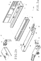
- the first rear connecting device 24 includes a main body 116 and a movable element 118 in addition to the locking element 30.
- the main body 116 includes a supporting portion 120 and a transverse portion 122 substantially perpendicularly connected to the supporting portion 120.
- the supporting portion 120 of the main body 116 includes a first vertical wall 112a and a second vertical wall 112b.
- the first vertical wall 112a and the second vertical wall 112b are respectively and substantially perpendicularly connected to two opposite lateral sides of the transverse portion 122 of the main body 116.
- the first rear connecting device 24 includes at least one connecting hole 124 through which a connecting element (not shown) is passed to mount the first rear connecting device 24 to the rear portion 20b of the second rail 34 of the first slide rail assembly 16 (see FIG. 1 ).
- the first rear connecting device 24 may be integrally formed with the rear portion 20b of the second rail 34 of the first slide rail assembly 16.
- the transverse portion 122 of the main body 116 includes a plurality of fixing portions 126 which are arranged at intervals.
- Each fixing portion 126 of the transverse portion 122 of the main body 116 is a recess 128.
- each of the first vertical wall 112a and the second vertical wall 112b has a through hole 130, and the through holes 130 correspond in position to each other.
- the locking element 30 is pivotally connected to the supporting portion 120 of the main body 116.
- the locking element 30 includes a head 132 and a locking rod 134 connected to the head 132, wherein the locking rod 134 has a contact portion 136.
- the locking rod 134 of the locking element 30 is pivotally provided in the through holes 130 of the first vertical wall 112a and the second vertical wall 112b.
- the movable element 118 is movably provided between the main body 116 and the locking element 30.
- the movable element 118 includes a first plate portion 138a and a second plate portion 138b perpendicular to the first plate portion 138a.
- the first plate portion 138a of the movable element 118 includes a fixing portion 140 corresponding in position to one of the fixing portions 126 of the transverse portion 122 of the main body 116.
- the fixing portion 140 of the first plate portion 138a is a rib 142 corresponding in structure to each recess 128 in the transverse portion 122 of the main body 116.
- the movable element 118 has a width L1 less than a width L2 between the first vertical wall 112a and the second vertical wall 112b of the main body 116. This allows the movable element 118 to move between the first vertical wall 112a and the second vertical wall 112b of the main body 116.
- the contact portion 136 of the locking rod 134 of the locking element 30 is pressed against the first plate portion 138a of the movable element 118 such that the rib 142 of the first plate portion 138a of the movable element 118 is engaged in one of the recesses 128 of the transverse portion 122 of the main body 116.
- the first plate portion 138a of the movable element 118 can be fixed at the mounting position to enable alignment of the drawer 10 (see FIG. 1 ), i.e., allowing the back panel of the drawer 10 to align with and be mounted to the first plate portion 138a.
- the operator can rotate the head 132 of the locking element 30 from the first position to a second position so that the contact portion 136 of the locking rod 134 of the locking element 30 is no longer pressed against the first plate portion 138a of the movable element 118.
- This allows the rib 142 of the first plate portion 138a of the movable element 118 to disengage from the one of the recesses 128 of the transverse portion 122 of the main body 116, and consequently the movable element 118 to displace relative to the main body 116.
- the movable element 118 which includes the first plate portion 138a, can be adjusted in position to adapt to mounting errors between the drawer 10 and the first plate portion 138a of the movable element 118, thereby eliminating the difficulty of alignment therebetween.
- the operator can operate the locking element 30 so that, by adjusting the position of the movable element 118, which includes the first plate portion 138a, the first plate portion 138a is aligned with the positioning hole 146 in the back panel 144 of the drawer 10 to eliminate mounting errors between the back panel 144 of the drawer 10 and the first plate portion 138a of the movable element 118.
- FIG. 7a and FIG. 7b show the second embodiment of the rear connecting device.
- This embodiment is different from the embodiment in FIG. 4a and FIG. 4b only in that each fixing portion of the transverse portion 202 of the main body 200 is a rib 204, and that the fixing portion of the first plate portion 208 of the movable element 206 is a recess 210.
- the second embodiment has the same technical effects as the embodiment in FIG. 4a and FIG. 4b , further description is omitted here for brevity.
- FIG. 8a and FIG. 8b show the third embodiment of the rear connecting device.
- This embodiment is different from the embodiments in FIGS. 4a, 4b and FIGS. 7a, 7b only in that each fixing portion 304 of the transverse portion 302 of the main body 300 is a flat surface (without any rib or recess), and that the fixing portion 310 of the first plate portion 308 of the movable element 306 is also a flat surface (without any rib or recess).
- the third embodiment has substantially the same technical effects as the embodiments in FIGS. 4a, 4b and FIGS. 7a, 7b .
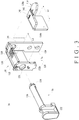
- the first front connecting device 12 includes a first unit 48, a second unit 50, an engaging element 52, and a disengaging element 54, in addition to the adjusting element 28.
- the first unit 48 includes a main body 56, a front wall 58 located at a front portion of the main body 56, and a sidewall 60 located at a lateral side of the main body 56.
- the main body 56 of the first unit 48 has at least one transverse guiding portion 62 which is substantially parallel to the front wall 58.
- the at least one transverse guiding portion 62 of the first unit 48 may be formed as one or more transverse guiding holes.
- the at least one transverse guiding portion 62 of the first unit 48 is implemented by a first transverse guiding hole 64a and a second transverse guiding hole 64b by way of example.
- the at least one transverse guiding portion 62 of the first unit 48 is one or more protruding blocks.
- the "transverse" direction refers to a direction perpendicular to the longitudinally extending main body 42 of the first rail 32 or the longitudinally extending main body 44 of the second rail 34.
- the main body 56 of the first unit 48 further includes at least one transverse guiding groove between the first transverse guiding hole 64a and the front wall 58.
- the at least one transverse guiding groove is implemented by a first transverse guiding groove 66a and a second transverse guiding groove 66b, wherein the first transverse guiding groove 66a and the second transverse guiding groove 66b are arranged substantially in a line.
- the main body 56 of the first unit 48 is provided with an aperture 68 between the first transverse guiding hole 64a and the second transverse guiding hole 64b.
- the front wall 58 of the first unit 48 is provided with a mounting portion (e.g., mounting holes 70) which, together with a mounting element (not shown), allows the first unit 48 to be mounted to the drawer 10, and yet the mounting method of the first unit 48 is not limited to the above.
- the sidewall 60 of the first unit 48 includes a threaded hole 72.
- the second unit 50 includes a main body 74, a first sidewall 76 located at a lateral side of the main body 74, and a second sidewall 78 located at the opposite lateral side of the main body 74 and facing the first sidewall 76.
- the main body 74 of the second unit 50 corresponds in position to the main body 56 of the first unit 48.
- the main body 74 of the second unit 50 has at least one transverse guiding portion 80 corresponding in position to and located at the transverse guiding portion 62 of the first unit 48 so as to be guided by the transverse guiding portion 62 of the first unit 48.
- the at least one transverse guiding portion 80 of the second unit 50 is implemented by a first protruding block 82a and a second protruding block 82b by way of example.
- the second unit 50 can slide smoothly relative to the first unit 48.
- the at least one transverse guiding portion 80 of the second unit 50 is one or more transverse guiding holes corresponding in position to one or more protruding blocks (i.e., the at least one transverse guiding portion 62) of the first unit 48.
- the main body 74 of the second unit 50 further includes a transverse hole 84 whose dimensions, in particular the transverse width, are greater than those of the aperture 68 of the first unit 48.
- a first connecting element 86 is passed through the transverse hole 84 of the second unit 50 and the aperture 68 of the first unit 48 to connect the first unit 48 and the second unit 50.
- the first connecting element 86 once positioned in the transverse hole 84 and the aperture 68, serves to guide and facilitate the sliding action of the second unit 50 relative to the first unit 48.
- a front portion of the main body 74 of the second unit 50 further includes an edge 88 to be pressed against the first transverse guiding groove 66a and the second transverse guiding groove 66b of the first unit 48.
- the edge 88 of the main body 74 of the second unit 50 includes a protruding portion 90 for indicating the displacement distance of the second unit 50 relative to the first unit 48.
- the first sidewall 76 of the second unit 50 includes a hanging hole 92
- the second sidewall 78 of the second unit 50 has a wall hole 94.
- the engaging element 52 is connected to the second unit 50.
- the engaging element 52 has a main body 96, an engaging portion 98 located at a lateral side of the main body 96, an elastic arm 100 located at the opposite lateral side of the main body 96, and a slot 102 in the main body 96.
- the engaging element 52 is pivotally connected to the second unit 50 via a second connecting element 104.
- the engaging element 52 can be pivoted relative to the second unit 50 by a predetermined angle.
- At least a portion of the engaging portion 98 is located and mounted in the mounting hole 46 of the second rail 34 (as can be seen more clearly in FIG. 11b ). More specifically, when the engaging element 52 is pivotally connected to the main body 74 of the second unit 50, the engaging portion 98 of the engaging element 52 corresponds in position to the wall hole 94 in the second sidewall 78 of the second unit 50 and can be adjusted in position by means of the adjusting element 28. The engaging portion 98 of the engaging element 52, once extending through the wall hole 94 of the second unit 50, can be engaged in the mounting hole 46 of the second rail 34 to connect the first front connecting device 12 to the second rail 34.
- the engaging portion 98 of the engaging element 52 has a step-like structure to adapt to mounting errors between the first front connecting device 12 and the mounting hole 46 of the second rail 34. For example, if a first mounting error (or a first distance error) exists between the engaging portion 98 of the engaging element 52 and the mounting hole 46 of the second rail 34, the first front connecting device 12 can be mounted in the mounting hole 46 of the second rail 34 via a first stage of the step-like structure. Similarly, if a second mounting error (or a second distance error) exists between the engaging portion 98 of the engaging element 52 and the mounting hole 46 of the second rail 34, the first front connecting device 12 can be mounted in the mounting hole 46 of the second rail 34 via a second stage of the step-like structure.
- the elastic arm 100 extends from a portion of the main body 96 of the engaging element 52 and is located on the lateral side of the main body 96 that is opposite the engaging portion 98.
- the elastic arm 100 is generally U-shaped and has an end portion to contact against the second unit 50.
- the disengaging element 54 is pivotally connected to the main body 74 of the second unit 50 via a third connecting element 106.
- the disengaging element 54 has a disengaging portion 108 located in the slot 102 of the main body 96 of the engaging element 52.
- the disengaging portion 108 is substantially an elliptic cylinder (but is not limited thereto) and is in contact with the wall surface of the slot 102.
- the adjusting element 28 has an adjusting portion 110 and a screw rod 112.
- the screw rod 112 is connected to the first unit 48 and the second unit 50. More specifically, the screw rod 112 of the adjusting element 28 is threadedly connected to the threaded hole 72 of the first unit 48, and the second unit 50 hangs on the neck 114 of the screw rod 112 via the hanging hole 92.
- the first unit 48 is marked with a plurality of characteristic marks, including a first characteristic mark K1, a second characteristic mark K2, a third characteristic mark K3, a fourth characteristic mark K4, and a fifth characteristic mark K5.
- the engaging portion 98 of the engaging element 52 of the first front connecting device 12 cannot extend, let alone be mounted, into the mounting hole 46 of the second rail 34 of the first slide rail assembly 16 without the operator rotating the adjusting portion 110 of the adjusting element 28. In other words, unless the adjusting portion 110 of the adjusting element 28 is rotated, the first front connecting device 12 in this position cannot be connected to the second rail 34 of the first slide rail assembly 16.
- the second unit 50 is displaced relative to the second rail 34 of the first slide rail assembly 16.
- the distance between the engaging portion 98 of the engaging element 52 and the mounting hole 46 of the second rail 34 is adjusted with the displacement of the second unit 50. More specifically, when the adjusting portion 110 of the adjusting element 28 is rotated (at which time the protruding portion 90 of the second unit 50 is displaced from the third characteristic mark K3 to the fifth characteristic mark K5, meaning that the second unit 50 is moved from the first position to a second position), the second unit 50 is displaced stably toward the first slide rail assembly 16 due to, referring back to FIG.
Landscapes
- Drawers Of Furniture (AREA)
Claims (6)
- Système de rails coulissant, caractérisé par le fait qu'il comprend :un ensemble de rails coulissant (16) caractérisé par le fait qu'il comprend :un premier rail (32) présentant un corps principal s'étendant longitudinalement (42) ; et un second rail (34) coulissant longitudinalement par rapport au premier rail (32), le second rail (34) présentant un corps principal s'étendant longitudinalement (44), et une partie arrière (20b) ; et un dispositif de raccordement arrière (24), caractérisé par le fait qu'il comprend ;un corps principal (116, 200, 300) caractérisé par le fait qu'il comprend une partie de support (120) et une partie transversale (122, 202, 302) substantiellement perpendiculaire raccordée à la partie de support (120) ;un élément de verrouillage (30, 312) raccordé de manière pivotante à la partie de support (120) du corps principal (116, 200, 300), l'élément de verrouillage (30, 312) caractérisé par le fait qu'il comprend une tête (132, 314) et une tige de verrouillage (134, 316) raccordée à la tête (132, 314), la tige de verrouillage (134, 316) présentant une partie de contact (136, 318) ; etun élément mobile (118, 206, 306) disposé de manière mobile entre le corps principal (116, 200, 300) et l'élément de verrouillage (30, 312), l'élément mobile (118, 206, 306) caractérisé par le fait qu'il comprend une première partie de plaque (138a, 208, 308) et une seconde partie de plaque (138b) substantiellement perpendiculaire par rapport à la première partie de plaque (138a, 208, 308) ;le dispositif de raccordement arrière (24) est situé sur la partie arrière (20b) du second rail (34), caractérisé en ce que, lorsque la tête (132, 314) de l'élément de verrouillage (30, 312) est tournée vers une première position, la partie de contact (136, 318) de la tige de verrouillage (134, 316) est comprimée contre la première partie de plaque (138a, 208, 308) de l'élément mobile (118, 206, 306) de sorte que l'élément mobile (118, 206, 306) est positionné sur le corps principal (116, 200, 300) ; eten ce que, dès que la tête (132, 314) de l'élément de verrouillage (30, 312) est tournée depuis la première position vers une seconde position, la partie de contact (136, 318) de la tige de verrouillage (134, 316) n'est plus comprimée contre la première partie de plaque (138a, 208, 308) de l'élément mobile (118, 206, 306), et l'élément mobile (118, 206, 306) peut donc être déplacé par rapport au corps principal (116, 200, 300).
- Système de rails coulissant selon la revendication 1, caractérisé par le fait que la partie de support (120) du corps principal (116, 200, 300) comprend une première paroi verticale (112a) et une seconde paroi verticale (112b), la partie transversale (122, 202, 302) du corps principal (116, 200, 300) présente des côtés latéraux opposés respectivement et substantiellement perpendiculaires raccordés à la première paroi verticale (112a) et à la seconde paroi verticale (112b), chacune des première paroi verticale (112a) et seconde paroi verticale (112b) présente un trou traversant (130), les trous traversants (130) correspondant en position les uns aux autres, la tige de verrouillage (134, 316) de l'élément de verrouillage (30, 312) se prolonge à travers les trous traversants (130) de la première paroi verticale (112a) et de la seconde paroi verticale (112b), et l'élément mobile (118, 206, 306) présente une largeur (L1) inférieure à une largeur (L2) entre la première paroi verticale (112a) et la seconde paroi verticale (112b) de sorte que l'élément mobile (118, 206, 306) est déplaçable entre la première paroi verticale (112a) et la seconde paroi verticale (112b).
- Système de rails coulissant selon la revendication 1 ou 2, caractérisé par le fait que la partie transversale (122, 202, 302) du corps principal (116, 200, 300) comprend une pluralité de parties de fixation (126, 304) placées à intervalles ; que la première partie de plaque (138a, 208, 308) de l'élément mobile (118, 206, 306) comprend une partie de fixation (140, 310) correspondant en position à l'une des parties de fixation (126, 304) de la partie transversale (122, 202, 302) du corps principal (116, 200, 300) ; lorsque la tête (132, 314) de l'élément de verrouillage (30, 312) est tournée vers la première position, la partie de contact (136, 318) de la tige de verrouillage (134, 316) est comprimée contre la première partie de plaque (138a, 208, 308) de l'élément mobile (118, 206, 306) de sorte que la partie de fixation (140, 310) de la première partie de plaque (138a, 208, 308) de l'élément mobile (118, 206, 306) est engagée avec l'une des parties de fixation (126, 304) de la partie transversale (122, 202, 302) du corps principal (116, 200, 300) ; et dès que la tête (132, 314) de l'élément de verrouillage (30, 312) est tournée depuis la première position vers une seconde position, la partie de contact (136, 318) de la tige de verrouillage (134, 316) n'est plus comprimée contre la première partie de plaque (138a, 208, 308) de l'élément mobile (118, 206, 306), et la partie de fixation (140, 310) de la première partie de plaque (138a, 208, 308) de l'élément mobile (118, 206, 306) est par conséquent désengagée de l'une des parties de fixation (126, 304) de la partie transversale (122, 202, 302) du corps principal (116, 200, 300).
- Système de rails coulissant selon l'une ou plusieurs des revendications 1-3, caractérisé par le fait que le second rail (34) présente en outre une partie avant (20a) opposée à la partie arrière (20b) et présente un trou de montage (46) adjacent à la partie avant (20a), et caractérisé par le fait que le système de rails coulissant comprend en outre un dispositif de raccordement avant (12), le dispositif de raccordement avant (12) caractérisé par le fait qu'il comprend :une première unité (48) présentant au moins une partie de guidage transversale (62) ;une seconde unité (50) présentant au moins une partie de guidage transversale (80) située sur la partie de guidage transversale (62) de la première unité (48) ;un élément d'engagement (52) raccordé à la seconde unité (50), l'élément d'engagement (52) présentant une partie d'engagement (98) au moins partiellement située dans le trou de montage (46) du second rail (34) ; etun élément de réglage (28) présentant une partie de réglage (110) et une tige filetée (112), la tige filetée (112) étant raccordée à la première unité (48) et à la seconde unité (50) ;la seconde unité (50) est déplaçable par rapport au second rail (34) en réponse à la rotation de la partie de réglage (110) de l'élément de réglage (28), ce qui permet le déplacement de la partie d'engagement (98) de l'élément d'engagement (52) par rapport au trou de montage (46) du second rail (34).
- Système de rails coulissant selon la revendication 4, caractérisé par le fait que la seconde unité (50) comprend en outre une première paroi latérale (76) présentant un trou de suspension (92) ; la première unité (48) comprend en outre une paroi latérale (60) présentant un trou filetée (72), la tige filetée (112) de l'élément de réglage (28) étant raccordée par filetage au trou fileté (72) alors que la seconde unité (50) est en suspension sur un col (114) de la tige filetée (112) via le trou de suspension (92) ; et la seconde unité (50) comprend en outre une seconde paroi latérale (78) opposée à la première paroi latérale (76), la seconde paroi latérale (78) présentant un trou de paroi (94), la partie d'engagement (98) de l'élément d'engagement (52) correspondant en position au trou de paroi (94).
- Système de rails coulissant selon la revendication 4 ou 5, caractérisé par le fait que l'élément d'engagement (52) comprend en outre un bras élastique (100), et lorsque la partie de réglage (110) de l'élément de réglage (28) est tournée, la seconde unité (50) est déplacée par rapport au second rail (34), la partie d'engagement (98) de l'élément d'engagement (52) si sa position ne correspond pas encore au trou de montage (46) du second rail (34) est comprimée contre une paroi latérale du second rail (34) et orientée d'un angle prédéterminé de sorte que le bras élastique (100) emmagasine une énergie élastique, et la partie d'engagement (98) de l'élément d'engagement (52), correspondant en position à un moment au trou de montage (46), pénètre dans le trou de montage (46) du fait de l'énergie élastique libérée par le bras élastique (100) ; et caractérisé par le fait que l'élément d'engagement (52) comprend en outre une rainure (102), le dispositif de raccordement avant (12) comprend en outre un élément de désengagement (54) raccordé de manière pivotante à la seconde unité (50), l'élément de désengagement (54) présentant une partie de désengagement (108) située dans la rainure (102), et lorsque l'élément de désengagement (54) est pivoté, la partie de désengagement (108) de l'élément de désengagement (54) entraîne l'élément d'engagement (52) via la rainure (102) et fait ainsi pivoter l'élément d'engagement (52) de sorte que la partie d'engagement (98) de l'élément d'engagement (52) est déplacée par rapport au second rail (34) et se sépare du trou de montage (46).
Priority Applications (1)
| Application Number | Priority Date | Filing Date | Title |
|---|---|---|---|
| EP14165554.8A EP2937018B1 (fr) | 2014-04-23 | 2014-04-23 | Système de rail de coulissement avec dispositif de raccordement utilisé pour l'ensemble rail coulissant |
Applications Claiming Priority (1)
| Application Number | Priority Date | Filing Date | Title |
|---|---|---|---|
| EP14165554.8A EP2937018B1 (fr) | 2014-04-23 | 2014-04-23 | Système de rail de coulissement avec dispositif de raccordement utilisé pour l'ensemble rail coulissant |
Publications (2)
| Publication Number | Publication Date |
|---|---|
| EP2937018A1 EP2937018A1 (fr) | 2015-10-28 |
| EP2937018B1 true EP2937018B1 (fr) | 2018-01-10 |
Family
ID=50513789
Family Applications (1)
| Application Number | Title | Priority Date | Filing Date |
|---|---|---|---|
| EP14165554.8A Active EP2937018B1 (fr) | 2014-04-23 | 2014-04-23 | Système de rail de coulissement avec dispositif de raccordement utilisé pour l'ensemble rail coulissant |
Country Status (1)
| Country | Link |
|---|---|
| EP (1) | EP2937018B1 (fr) |
Families Citing this family (3)
| Publication number | Priority date | Publication date | Assignee | Title |
|---|---|---|---|---|
| TWI639400B (zh) * | 2017-08-17 | 2018-11-01 | 南俊國際股份有限公司 | 具快拆組件之滑軌裝置 |
| DE102017121845A1 (de) * | 2017-09-20 | 2019-03-21 | Paul Hettich Gmbh & Co. Kg | Kupplungsvorrichtung mit Nachverrastung |
| CN109090866A (zh) * | 2018-11-12 | 2018-12-28 | 广东顺德瑞美高五金科技有限公司 | 一种便于安装的骑马抽用连接锁件 |
Family Cites Families (9)
| Publication number | Priority date | Publication date | Assignee | Title |
|---|---|---|---|---|
| US2756956A (en) * | 1952-08-14 | 1956-07-31 | William A Anderson | Mounting for cameras and the like |
| US3787133A (en) * | 1971-03-16 | 1974-01-22 | C Geurts | Clamp and positioning structure |
| US4786204A (en) * | 1986-02-24 | 1988-11-22 | The Eversman Mfg. Company | Clamping apparatus with bi-directional clamping device |
| GB2397328B (en) * | 2003-01-15 | 2004-10-20 | K H S Musical Instr Co Ltd | Quick-release for a music support stand |
| DE202007014954U1 (de) * | 2007-10-31 | 2008-12-18 | Grass Gmbh | Vorrichtung zur Anbringung einer Führungseinheit sowie Möbelteil und Möbel mit einer solchen Vorrichtung |
| AT508265B1 (de) * | 2009-06-10 | 2013-05-15 | Blum Gmbh Julius | Ausziehführung für schubladen |
| AT509414B1 (de) | 2010-02-03 | 2013-04-15 | Blum Gmbh Julius | Kupplungsvorrichtung mit seitenverstellung für eine schublade |
| AT509416B1 (de) | 2010-02-03 | 2012-05-15 | Blum Gmbh Julius | Ausziehführung für eine schublade |
| AT511418B1 (de) * | 2011-05-05 | 2014-11-15 | Blum Gmbh Julius | Ausziehführung für eine schublade |
-
2014
- 2014-04-23 EP EP14165554.8A patent/EP2937018B1/fr active Active
Non-Patent Citations (1)
| Title |
|---|
| None * |
Also Published As
| Publication number | Publication date |
|---|---|
| EP2937018A1 (fr) | 2015-10-28 |
Similar Documents
| Publication | Publication Date | Title |
|---|---|---|
| US9066587B1 (en) | Slide rail system and connecting device used for slide rail assembly | |
| US8854769B1 (en) | Slide rail system and connecting device used for slide rail assembly | |
| US9629459B2 (en) | Slide rail assembly | |
| US20160186895A1 (en) | Cable management arm | |
| EP3082387B1 (fr) | Ensemble de rail de glissement | |
| US9125489B2 (en) | Fixing device for a slide assembly | |
| EP3136830B1 (fr) | Ensemble rail coulissant et son dispositif de support | |
| US20150282617A1 (en) | Adjusting device | |
| EP3148304A2 (fr) | Ensemble rail coulissant et son dispositif de support | |
| KR101268912B1 (ko) | 가구힌지의 가구도어 위치 조절장치 | |
| US10010174B2 (en) | Mounting mechanism | |
| US8672286B2 (en) | Adjustable wall hanger | |
| EP2929804A1 (fr) | Système de rail de coulissement et dispositif de raccordement utilisé pour l'ensemble rail coulissant | |
| EP2937018B1 (fr) | Système de rail de coulissement avec dispositif de raccordement utilisé pour l'ensemble rail coulissant | |
| EP2728096A2 (fr) | Ensemble de porte de douche | |
| CN101396207B (zh) | 抽屉组件 | |
| US20080303399A1 (en) | Front installing drawer pulling force adjusting apparatus | |
| US20140175726A1 (en) | Rapidly locking/unlocking extension work table | |
| EP3041329A1 (fr) | Bras de gestion de câbles | |
| EP3030065B1 (fr) | Dispositif de support de bras de gestion de câble et ensemble de montage de celui-ci | |
| JP3191618U (ja) | スライドレールシステム及び当該スライドレールシステムに用いられる連結装置 | |
| CN107581807B (zh) | 安装机构 | |
| TW201529013A (zh) | 滑軌總成及用於滑軌總成的連接裝置 | |
| TWI513434B (zh) | 滑軌總成及用於滑軌總成的連接裝置 | |
| CN104840020B (zh) | 滑轨总成及用于滑轨总成的连接装置 |
Legal Events
| Date | Code | Title | Description |
|---|---|---|---|
| PUAI | Public reference made under article 153(3) epc to a published international application that has entered the european phase |
Free format text: ORIGINAL CODE: 0009012 |
|
| AK | Designated contracting states |
Kind code of ref document: A1 Designated state(s): AL AT BE BG CH CY CZ DE DK EE ES FI FR GB GR HR HU IE IS IT LI LT LU LV MC MK MT NL NO PL PT RO RS SE SI SK SM TR |
|
| AX | Request for extension of the european patent |
Extension state: BA ME |
|
| 17P | Request for examination filed |
Effective date: 20151030 |
|
| RBV | Designated contracting states (corrected) |
Designated state(s): AL AT BE BG CH CY CZ DE DK EE ES FI FR GB GR HR HU IE IS IT LI LT LU LV MC MK MT NL NO PL PT RO RS SE SI SK SM TR |
|
| REG | Reference to a national code |
Ref country code: DE Ref legal event code: R079 Ref document number: 602014019600 Country of ref document: DE Free format text: PREVIOUS MAIN CLASS: A47B0088040000 Ipc: A47B0088427000 |
|
| RIC1 | Information provided on ipc code assigned before grant |
Ipc: A47B 88/427 20170101AFI20170530BHEP |
|
| GRAP | Despatch of communication of intention to grant a patent |
Free format text: ORIGINAL CODE: EPIDOSNIGR1 |
|
| INTG | Intention to grant announced |
Effective date: 20170731 |
|
| GRAS | Grant fee paid |
Free format text: ORIGINAL CODE: EPIDOSNIGR3 |
|
| GRAA | (expected) grant |
Free format text: ORIGINAL CODE: 0009210 |
|
| AK | Designated contracting states |
Kind code of ref document: B1 Designated state(s): AL AT BE BG CH CY CZ DE DK EE ES FI FR GB GR HR HU IE IS IT LI LT LU LV MC MK MT NL NO PL PT RO RS SE SI SK SM TR |
|
| REG | Reference to a national code |
Ref country code: CH Ref legal event code: EP Ref country code: AT Ref legal event code: REF Ref document number: 961474 Country of ref document: AT Kind code of ref document: T Effective date: 20180115 |
|
| REG | Reference to a national code |
Ref country code: IE Ref legal event code: FG4D |
|
| REG | Reference to a national code |
Ref country code: DE Ref legal event code: R096 Ref document number: 602014019600 Country of ref document: DE |
|
| REG | Reference to a national code |
Ref country code: NL Ref legal event code: MP Effective date: 20180110 |
|
| REG | Reference to a national code |
Ref country code: AT Ref legal event code: MK05 Ref document number: 961474 Country of ref document: AT Kind code of ref document: T Effective date: 20180110 |
|
| PG25 | Lapsed in a contracting state [announced via postgrant information from national office to epo] |
Ref country code: NL Free format text: LAPSE BECAUSE OF FAILURE TO SUBMIT A TRANSLATION OF THE DESCRIPTION OR TO PAY THE FEE WITHIN THE PRESCRIBED TIME-LIMIT Effective date: 20180110 |
|
| PG25 | Lapsed in a contracting state [announced via postgrant information from national office to epo] |
Ref country code: LT Free format text: LAPSE BECAUSE OF FAILURE TO SUBMIT A TRANSLATION OF THE DESCRIPTION OR TO PAY THE FEE WITHIN THE PRESCRIBED TIME-LIMIT Effective date: 20180110 Ref country code: CY Free format text: LAPSE BECAUSE OF FAILURE TO SUBMIT A TRANSLATION OF THE DESCRIPTION OR TO PAY THE FEE WITHIN THE PRESCRIBED TIME-LIMIT Effective date: 20180110 Ref country code: NO Free format text: LAPSE BECAUSE OF FAILURE TO SUBMIT A TRANSLATION OF THE DESCRIPTION OR TO PAY THE FEE WITHIN THE PRESCRIBED TIME-LIMIT Effective date: 20180410 Ref country code: FI Free format text: LAPSE BECAUSE OF FAILURE TO SUBMIT A TRANSLATION OF THE DESCRIPTION OR TO PAY THE FEE WITHIN THE PRESCRIBED TIME-LIMIT Effective date: 20180110 Ref country code: ES Free format text: LAPSE BECAUSE OF FAILURE TO SUBMIT A TRANSLATION OF THE DESCRIPTION OR TO PAY THE FEE WITHIN THE PRESCRIBED TIME-LIMIT Effective date: 20180110 Ref country code: HR Free format text: LAPSE BECAUSE OF FAILURE TO SUBMIT A TRANSLATION OF THE DESCRIPTION OR TO PAY THE FEE WITHIN THE PRESCRIBED TIME-LIMIT Effective date: 20180110 |
|
| PG25 | Lapsed in a contracting state [announced via postgrant information from national office to epo] |
Ref country code: PL Free format text: LAPSE BECAUSE OF FAILURE TO SUBMIT A TRANSLATION OF THE DESCRIPTION OR TO PAY THE FEE WITHIN THE PRESCRIBED TIME-LIMIT Effective date: 20180110 Ref country code: RS Free format text: LAPSE BECAUSE OF FAILURE TO SUBMIT A TRANSLATION OF THE DESCRIPTION OR TO PAY THE FEE WITHIN THE PRESCRIBED TIME-LIMIT Effective date: 20180110 Ref country code: SE Free format text: LAPSE BECAUSE OF FAILURE TO SUBMIT A TRANSLATION OF THE DESCRIPTION OR TO PAY THE FEE WITHIN THE PRESCRIBED TIME-LIMIT Effective date: 20180110 Ref country code: BG Free format text: LAPSE BECAUSE OF FAILURE TO SUBMIT A TRANSLATION OF THE DESCRIPTION OR TO PAY THE FEE WITHIN THE PRESCRIBED TIME-LIMIT Effective date: 20180410 Ref country code: AT Free format text: LAPSE BECAUSE OF FAILURE TO SUBMIT A TRANSLATION OF THE DESCRIPTION OR TO PAY THE FEE WITHIN THE PRESCRIBED TIME-LIMIT Effective date: 20180110 Ref country code: IS Free format text: LAPSE BECAUSE OF FAILURE TO SUBMIT A TRANSLATION OF THE DESCRIPTION OR TO PAY THE FEE WITHIN THE PRESCRIBED TIME-LIMIT Effective date: 20180510 Ref country code: LV Free format text: LAPSE BECAUSE OF FAILURE TO SUBMIT A TRANSLATION OF THE DESCRIPTION OR TO PAY THE FEE WITHIN THE PRESCRIBED TIME-LIMIT Effective date: 20180110 |
|
| REG | Reference to a national code |
Ref country code: DE Ref legal event code: R097 Ref document number: 602014019600 Country of ref document: DE |
|
| PG25 | Lapsed in a contracting state [announced via postgrant information from national office to epo] |
Ref country code: RO Free format text: LAPSE BECAUSE OF FAILURE TO SUBMIT A TRANSLATION OF THE DESCRIPTION OR TO PAY THE FEE WITHIN THE PRESCRIBED TIME-LIMIT Effective date: 20180110 Ref country code: IT Free format text: LAPSE BECAUSE OF FAILURE TO SUBMIT A TRANSLATION OF THE DESCRIPTION OR TO PAY THE FEE WITHIN THE PRESCRIBED TIME-LIMIT Effective date: 20180110 Ref country code: EE Free format text: LAPSE BECAUSE OF FAILURE TO SUBMIT A TRANSLATION OF THE DESCRIPTION OR TO PAY THE FEE WITHIN THE PRESCRIBED TIME-LIMIT Effective date: 20180110 Ref country code: AL Free format text: LAPSE BECAUSE OF FAILURE TO SUBMIT A TRANSLATION OF THE DESCRIPTION OR TO PAY THE FEE WITHIN THE PRESCRIBED TIME-LIMIT Effective date: 20180110 |
|
| PLBE | No opposition filed within time limit |
Free format text: ORIGINAL CODE: 0009261 |
|
| STAA | Information on the status of an ep patent application or granted ep patent |
Free format text: STATUS: NO OPPOSITION FILED WITHIN TIME LIMIT |
|
| PG25 | Lapsed in a contracting state [announced via postgrant information from national office to epo] |
Ref country code: SK Free format text: LAPSE BECAUSE OF FAILURE TO SUBMIT A TRANSLATION OF THE DESCRIPTION OR TO PAY THE FEE WITHIN THE PRESCRIBED TIME-LIMIT Effective date: 20180110 Ref country code: SM Free format text: LAPSE BECAUSE OF FAILURE TO SUBMIT A TRANSLATION OF THE DESCRIPTION OR TO PAY THE FEE WITHIN THE PRESCRIBED TIME-LIMIT Effective date: 20180110 Ref country code: DK Free format text: LAPSE BECAUSE OF FAILURE TO SUBMIT A TRANSLATION OF THE DESCRIPTION OR TO PAY THE FEE WITHIN THE PRESCRIBED TIME-LIMIT Effective date: 20180110 Ref country code: MC Free format text: LAPSE BECAUSE OF FAILURE TO SUBMIT A TRANSLATION OF THE DESCRIPTION OR TO PAY THE FEE WITHIN THE PRESCRIBED TIME-LIMIT Effective date: 20180110 Ref country code: CZ Free format text: LAPSE BECAUSE OF FAILURE TO SUBMIT A TRANSLATION OF THE DESCRIPTION OR TO PAY THE FEE WITHIN THE PRESCRIBED TIME-LIMIT Effective date: 20180110 |
|
| REG | Reference to a national code |
Ref country code: CH Ref legal event code: PL |
|
| 26N | No opposition filed |
Effective date: 20181011 |
|
| REG | Reference to a national code |
Ref country code: BE Ref legal event code: MM Effective date: 20180430 |
|
| REG | Reference to a national code |
Ref country code: IE Ref legal event code: MM4A |
|
| PG25 | Lapsed in a contracting state [announced via postgrant information from national office to epo] |
Ref country code: LU Free format text: LAPSE BECAUSE OF NON-PAYMENT OF DUE FEES Effective date: 20180423 |
|
| PG25 | Lapsed in a contracting state [announced via postgrant information from national office to epo] |
Ref country code: SI Free format text: LAPSE BECAUSE OF FAILURE TO SUBMIT A TRANSLATION OF THE DESCRIPTION OR TO PAY THE FEE WITHIN THE PRESCRIBED TIME-LIMIT Effective date: 20180110 Ref country code: BE Free format text: LAPSE BECAUSE OF NON-PAYMENT OF DUE FEES Effective date: 20180430 Ref country code: CH Free format text: LAPSE BECAUSE OF NON-PAYMENT OF DUE FEES Effective date: 20180430 Ref country code: LI Free format text: LAPSE BECAUSE OF NON-PAYMENT OF DUE FEES Effective date: 20180430 |
|
| PG25 | Lapsed in a contracting state [announced via postgrant information from national office to epo] |
Ref country code: IE Free format text: LAPSE BECAUSE OF NON-PAYMENT OF DUE FEES Effective date: 20180423 Ref country code: FR Free format text: LAPSE BECAUSE OF NON-PAYMENT OF DUE FEES Effective date: 20180430 |
|
| PG25 | Lapsed in a contracting state [announced via postgrant information from national office to epo] |
Ref country code: MT Free format text: LAPSE BECAUSE OF NON-PAYMENT OF DUE FEES Effective date: 20180423 |
|
| PG25 | Lapsed in a contracting state [announced via postgrant information from national office to epo] |
Ref country code: TR Free format text: LAPSE BECAUSE OF FAILURE TO SUBMIT A TRANSLATION OF THE DESCRIPTION OR TO PAY THE FEE WITHIN THE PRESCRIBED TIME-LIMIT Effective date: 20180110 |
|
| PG25 | Lapsed in a contracting state [announced via postgrant information from national office to epo] |
Ref country code: PT Free format text: LAPSE BECAUSE OF FAILURE TO SUBMIT A TRANSLATION OF THE DESCRIPTION OR TO PAY THE FEE WITHIN THE PRESCRIBED TIME-LIMIT Effective date: 20180110 |
|
| PG25 | Lapsed in a contracting state [announced via postgrant information from national office to epo] |
Ref country code: HU Free format text: LAPSE BECAUSE OF FAILURE TO SUBMIT A TRANSLATION OF THE DESCRIPTION OR TO PAY THE FEE WITHIN THE PRESCRIBED TIME-LIMIT; INVALID AB INITIO Effective date: 20140423 Ref country code: GR Free format text: LAPSE BECAUSE OF FAILURE TO SUBMIT A TRANSLATION OF THE DESCRIPTION OR TO PAY THE FEE WITHIN THE PRESCRIBED TIME-LIMIT Effective date: 20180110 Ref country code: MK Free format text: LAPSE BECAUSE OF NON-PAYMENT OF DUE FEES Effective date: 20180110 |
|
| PGFP | Annual fee paid to national office [announced via postgrant information from national office to epo] |
Ref country code: GB Payment date: 20240409 Year of fee payment: 11 |
|
| PGFP | Annual fee paid to national office [announced via postgrant information from national office to epo] |
Ref country code: DE Payment date: 20240411 Year of fee payment: 11 |