EP2936770B1 - Vorrichtung und verfahren zur steuerung eines jitterpuffers - Google Patents
Vorrichtung und verfahren zur steuerung eines jitterpuffers Download PDFInfo
- Publication number
- EP2936770B1 EP2936770B1 EP13818147.4A EP13818147A EP2936770B1 EP 2936770 B1 EP2936770 B1 EP 2936770B1 EP 13818147 A EP13818147 A EP 13818147A EP 2936770 B1 EP2936770 B1 EP 2936770B1
- Authority
- EP
- European Patent Office
- Prior art keywords
- frame
- jitter buffer
- talkspurt
- jitter
- length
- Prior art date
- Legal status (The legal status is an assumption and is not a legal conclusion. Google has not performed a legal analysis and makes no representation as to the accuracy of the status listed.)
- Active
Links
Images


Classifications
-
- H—ELECTRICITY
- H04—ELECTRIC COMMUNICATION TECHNIQUE
- H04L—TRANSMISSION OF DIGITAL INFORMATION, e.g. TELEGRAPHIC COMMUNICATION
- H04L47/00—Traffic control in data switching networks
- H04L47/50—Queue scheduling
- H04L47/56—Queue scheduling implementing delay-aware scheduling
-
- H—ELECTRICITY
- H04—ELECTRIC COMMUNICATION TECHNIQUE
- H04L—TRANSMISSION OF DIGITAL INFORMATION, e.g. TELEGRAPHIC COMMUNICATION
- H04L65/00—Network arrangements, protocols or services for supporting real-time applications in data packet communication
- H04L65/80—Responding to QoS
-
- H—ELECTRICITY
- H04—ELECTRIC COMMUNICATION TECHNIQUE
- H04L—TRANSMISSION OF DIGITAL INFORMATION, e.g. TELEGRAPHIC COMMUNICATION
- H04L1/00—Arrangements for detecting or preventing errors in the information received
- H04L1/20—Arrangements for detecting or preventing errors in the information received using signal quality detector
- H04L1/205—Arrangements for detecting or preventing errors in the information received using signal quality detector jitter monitoring
-
- H—ELECTRICITY
- H04—ELECTRIC COMMUNICATION TECHNIQUE
- H04L—TRANSMISSION OF DIGITAL INFORMATION, e.g. TELEGRAPHIC COMMUNICATION
- H04L43/00—Arrangements for monitoring or testing data switching networks
- H04L43/08—Monitoring or testing based on specific metrics, e.g. QoS, energy consumption or environmental parameters
- H04L43/0852—Delays
- H04L43/087—Jitter
-
- H—ELECTRICITY
- H04—ELECTRIC COMMUNICATION TECHNIQUE
- H04L—TRANSMISSION OF DIGITAL INFORMATION, e.g. TELEGRAPHIC COMMUNICATION
- H04L47/00—Traffic control in data switching networks
- H04L47/10—Flow control; Congestion control
- H04L47/28—Flow control; Congestion control in relation to timing considerations
- H04L47/283—Flow control; Congestion control in relation to timing considerations in response to processing delays, e.g. caused by jitter or round trip time [RTT]
-
- H—ELECTRICITY
- H04—ELECTRIC COMMUNICATION TECHNIQUE
- H04W—WIRELESS COMMUNICATION NETWORKS
- H04W16/00—Network planning, e.g. coverage or traffic planning tools; Network deployment, e.g. resource partitioning or cells structures
- H04W16/18—Network planning tools
-
- H—ELECTRICITY
- H04—ELECTRIC COMMUNICATION TECHNIQUE
- H04W—WIRELESS COMMUNICATION NETWORKS
- H04W24/00—Supervisory, monitoring or testing arrangements
- H04W24/02—Arrangements for optimising operational condition
-
- H—ELECTRICITY
- H04—ELECTRIC COMMUNICATION TECHNIQUE
- H04W—WIRELESS COMMUNICATION NETWORKS
- H04W28/00—Network traffic management; Network resource management
- H04W28/02—Traffic management, e.g. flow control or congestion control
-
- H—ELECTRICITY
- H04—ELECTRIC COMMUNICATION TECHNIQUE
- H04W—WIRELESS COMMUNICATION NETWORKS
- H04W48/00—Access restriction; Network selection; Access point selection
- H04W48/18—Selecting a network or a communication service
-
- H—ELECTRICITY
- H04—ELECTRIC COMMUNICATION TECHNIQUE
- H04W—WIRELESS COMMUNICATION NETWORKS
- H04W72/00—Local resource management
- H04W72/04—Wireless resource allocation
-
- H—ELECTRICITY
- H04—ELECTRIC COMMUNICATION TECHNIQUE
- H04W—WIRELESS COMMUNICATION NETWORKS
- H04W72/00—Local resource management
- H04W72/12—Wireless traffic scheduling
-
- B—PERFORMING OPERATIONS; TRANSPORTING
- B60—VEHICLES IN GENERAL
- B60L—PROPULSION OF ELECTRICALLY-PROPELLED VEHICLES; SUPPLYING ELECTRIC POWER FOR AUXILIARY EQUIPMENT OF ELECTRICALLY-PROPELLED VEHICLES; ELECTRODYNAMIC BRAKE SYSTEMS FOR VEHICLES IN GENERAL; MAGNETIC SUSPENSION OR LEVITATION FOR VEHICLES; MONITORING OPERATING VARIABLES OF ELECTRICALLY-PROPELLED VEHICLES; ELECTRIC SAFETY DEVICES FOR ELECTRICALLY-PROPELLED VEHICLES
- B60L1/00—Supplying electric power to auxiliary equipment of vehicles
-
- B—PERFORMING OPERATIONS; TRANSPORTING
- B60—VEHICLES IN GENERAL
- B60L—PROPULSION OF ELECTRICALLY-PROPELLED VEHICLES; SUPPLYING ELECTRIC POWER FOR AUXILIARY EQUIPMENT OF ELECTRICALLY-PROPELLED VEHICLES; ELECTRODYNAMIC BRAKE SYSTEMS FOR VEHICLES IN GENERAL; MAGNETIC SUSPENSION OR LEVITATION FOR VEHICLES; MONITORING OPERATING VARIABLES OF ELECTRICALLY-PROPELLED VEHICLES; ELECTRIC SAFETY DEVICES FOR ELECTRICALLY-PROPELLED VEHICLES
- B60L2210/00—Converter types
- B60L2210/30—AC to DC converters
-
- B—PERFORMING OPERATIONS; TRANSPORTING
- B60—VEHICLES IN GENERAL
- B60L—PROPULSION OF ELECTRICALLY-PROPELLED VEHICLES; SUPPLYING ELECTRIC POWER FOR AUXILIARY EQUIPMENT OF ELECTRICALLY-PROPELLED VEHICLES; ELECTRODYNAMIC BRAKE SYSTEMS FOR VEHICLES IN GENERAL; MAGNETIC SUSPENSION OR LEVITATION FOR VEHICLES; MONITORING OPERATING VARIABLES OF ELECTRICALLY-PROPELLED VEHICLES; ELECTRIC SAFETY DEVICES FOR ELECTRICALLY-PROPELLED VEHICLES
- B60L2210/00—Converter types
- B60L2210/40—DC to AC converters
-
- B—PERFORMING OPERATIONS; TRANSPORTING
- B60—VEHICLES IN GENERAL
- B60L—PROPULSION OF ELECTRICALLY-PROPELLED VEHICLES; SUPPLYING ELECTRIC POWER FOR AUXILIARY EQUIPMENT OF ELECTRICALLY-PROPELLED VEHICLES; ELECTRODYNAMIC BRAKE SYSTEMS FOR VEHICLES IN GENERAL; MAGNETIC SUSPENSION OR LEVITATION FOR VEHICLES; MONITORING OPERATING VARIABLES OF ELECTRICALLY-PROPELLED VEHICLES; ELECTRIC SAFETY DEVICES FOR ELECTRICALLY-PROPELLED VEHICLES
- B60L53/00—Methods of charging batteries, specially adapted for electric vehicles; Charging stations or on-board charging equipment therefor; Exchange of energy storage elements in electric vehicles
- B60L53/10—Methods of charging batteries, specially adapted for electric vehicles; Charging stations or on-board charging equipment therefor; Exchange of energy storage elements in electric vehicles characterised by the energy transfer between the charging station and the vehicle
- B60L53/14—Conductive energy transfer
-
- B—PERFORMING OPERATIONS; TRANSPORTING
- B60—VEHICLES IN GENERAL
- B60L—PROPULSION OF ELECTRICALLY-PROPELLED VEHICLES; SUPPLYING ELECTRIC POWER FOR AUXILIARY EQUIPMENT OF ELECTRICALLY-PROPELLED VEHICLES; ELECTRODYNAMIC BRAKE SYSTEMS FOR VEHICLES IN GENERAL; MAGNETIC SUSPENSION OR LEVITATION FOR VEHICLES; MONITORING OPERATING VARIABLES OF ELECTRICALLY-PROPELLED VEHICLES; ELECTRIC SAFETY DEVICES FOR ELECTRICALLY-PROPELLED VEHICLES
- B60L55/00—Arrangements for supplying energy stored within a vehicle to a power network, i.e. vehicle-to-grid [V2G] arrangements
-
- H—ELECTRICITY
- H02—GENERATION; CONVERSION OR DISTRIBUTION OF ELECTRIC POWER
- H02M—APPARATUS FOR CONVERSION BETWEEN AC AND AC, BETWEEN AC AND DC, OR BETWEEN DC AND DC, AND FOR USE WITH MAINS OR SIMILAR POWER SUPPLY SYSTEMS; CONVERSION OF DC OR AC INPUT POWER INTO SURGE OUTPUT POWER; CONTROL OR REGULATION THEREOF
- H02M1/00—Details of apparatus for conversion
- H02M1/0067—Converter structures employing plural converter units, other than for parallel operation of the units on a single load
- H02M1/007—Plural converter units in cascade
-
- H—ELECTRICITY
- H02—GENERATION; CONVERSION OR DISTRIBUTION OF ELECTRIC POWER
- H02M—APPARATUS FOR CONVERSION BETWEEN AC AND AC, BETWEEN AC AND DC, OR BETWEEN DC AND DC, AND FOR USE WITH MAINS OR SIMILAR POWER SUPPLY SYSTEMS; CONVERSION OF DC OR AC INPUT POWER INTO SURGE OUTPUT POWER; CONTROL OR REGULATION THEREOF
- H02M1/00—Details of apparatus for conversion
- H02M1/14—Arrangements for reducing ripples from DC input or output
-
- H—ELECTRICITY
- H02—GENERATION; CONVERSION OR DISTRIBUTION OF ELECTRIC POWER
- H02M—APPARATUS FOR CONVERSION BETWEEN AC AND AC, BETWEEN AC AND DC, OR BETWEEN DC AND DC, AND FOR USE WITH MAINS OR SIMILAR POWER SUPPLY SYSTEMS; CONVERSION OF DC OR AC INPUT POWER INTO SURGE OUTPUT POWER; CONTROL OR REGULATION THEREOF
- H02M1/00—Details of apparatus for conversion
- H02M1/42—Circuits or arrangements for compensating for or adjusting power factor in converters or inverters
-
- H—ELECTRICITY
- H02—GENERATION; CONVERSION OR DISTRIBUTION OF ELECTRIC POWER
- H02M—APPARATUS FOR CONVERSION BETWEEN AC AND AC, BETWEEN AC AND DC, OR BETWEEN DC AND DC, AND FOR USE WITH MAINS OR SIMILAR POWER SUPPLY SYSTEMS; CONVERSION OF DC OR AC INPUT POWER INTO SURGE OUTPUT POWER; CONTROL OR REGULATION THEREOF
- H02M5/00—Conversion of AC power input into AC power output, e.g. for change of voltage, for change of frequency, for change of number of phases
- H02M5/40—Conversion of AC power input into AC power output, e.g. for change of voltage, for change of frequency, for change of number of phases with intermediate conversion into DC
- H02M5/42—Conversion of AC power input into AC power output, e.g. for change of voltage, for change of frequency, for change of number of phases with intermediate conversion into DC by static converters
- H02M5/44—Conversion of AC power input into AC power output, e.g. for change of voltage, for change of frequency, for change of number of phases with intermediate conversion into DC by static converters using discharge tubes or semiconductor devices to convert the intermediate DC into AC
- H02M5/453—Conversion of AC power input into AC power output, e.g. for change of voltage, for change of frequency, for change of number of phases with intermediate conversion into DC by static converters using discharge tubes or semiconductor devices to convert the intermediate DC into AC using devices of a triode or transistor type requiring continuous application of a control signal
- H02M5/458—Conversion of AC power input into AC power output, e.g. for change of voltage, for change of frequency, for change of number of phases with intermediate conversion into DC by static converters using discharge tubes or semiconductor devices to convert the intermediate DC into AC using devices of a triode or transistor type requiring continuous application of a control signal using semiconductor devices only
-
- H—ELECTRICITY
- H02—GENERATION; CONVERSION OR DISTRIBUTION OF ELECTRIC POWER
- H02M—APPARATUS FOR CONVERSION BETWEEN AC AND AC, BETWEEN AC AND DC, OR BETWEEN DC AND DC, AND FOR USE WITH MAINS OR SIMILAR POWER SUPPLY SYSTEMS; CONVERSION OF DC OR AC INPUT POWER INTO SURGE OUTPUT POWER; CONTROL OR REGULATION THEREOF
- H02M7/00—Conversion of AC power input into DC power output; Conversion of DC power input into AC power output
- H02M7/42—Conversion of DC power input into AC power output without possibility of reversal
- H02M7/44—Conversion of DC power input into AC power output without possibility of reversal by static converters
- H02M7/48—Conversion of DC power input into AC power output without possibility of reversal by static converters using discharge tubes with control electrode or semiconductor devices with control electrode
- H02M7/4807—Conversion of DC power input into AC power output without possibility of reversal by static converters using discharge tubes with control electrode or semiconductor devices with control electrode having a high frequency intermediate AC stage
-
- H—ELECTRICITY
- H02—GENERATION; CONVERSION OR DISTRIBUTION OF ELECTRIC POWER
- H02M—APPARATUS FOR CONVERSION BETWEEN AC AND AC, BETWEEN AC AND DC, OR BETWEEN DC AND DC, AND FOR USE WITH MAINS OR SIMILAR POWER SUPPLY SYSTEMS; CONVERSION OF DC OR AC INPUT POWER INTO SURGE OUTPUT POWER; CONTROL OR REGULATION THEREOF
- H02M7/00—Conversion of AC power input into DC power output; Conversion of DC power input into AC power output
- H02M7/66—Conversion of AC power input into DC power output; Conversion of DC power input into AC power output with possibility of reversal
- H02M7/68—Conversion of AC power input into DC power output; Conversion of DC power input into AC power output with possibility of reversal by static converters
- H02M7/72—Conversion of AC power input into DC power output; Conversion of DC power input into AC power output with possibility of reversal by static converters using discharge tubes with control electrode or semiconductor devices with control electrode
- H02M7/79—Conversion of AC power input into DC power output; Conversion of DC power input into AC power output with possibility of reversal by static converters using discharge tubes with control electrode or semiconductor devices with control electrode using devices of a triode or transistor type requiring continuous application of a control signal
-
- H—ELECTRICITY
- H04—ELECTRIC COMMUNICATION TECHNIQUE
- H04L—TRANSMISSION OF DIGITAL INFORMATION, e.g. TELEGRAPHIC COMMUNICATION
- H04L47/00—Traffic control in data switching networks
- H04L47/10—Flow control; Congestion control
- H04L47/24—Traffic characterised by specific attributes, e.g. priority or QoS
- H04L47/2416—Real-time traffic
-
- Y—GENERAL TAGGING OF NEW TECHNOLOGICAL DEVELOPMENTS; GENERAL TAGGING OF CROSS-SECTIONAL TECHNOLOGIES SPANNING OVER SEVERAL SECTIONS OF THE IPC; TECHNICAL SUBJECTS COVERED BY FORMER USPC CROSS-REFERENCE ART COLLECTIONS [XRACs] AND DIGESTS
- Y02—TECHNOLOGIES OR APPLICATIONS FOR MITIGATION OR ADAPTATION AGAINST CLIMATE CHANGE
- Y02B—CLIMATE CHANGE MITIGATION TECHNOLOGIES RELATED TO BUILDINGS, e.g. HOUSING, HOUSE APPLIANCES OR RELATED END-USER APPLICATIONS
- Y02B70/00—Technologies for an efficient end-user side electric power management and consumption
- Y02B70/10—Technologies improving the efficiency by using switched-mode power supplies [SMPS], i.e. efficient power electronics conversion e.g. power factor correction or reduction of losses in power supplies or efficient standby modes
-
- Y—GENERAL TAGGING OF NEW TECHNOLOGICAL DEVELOPMENTS; GENERAL TAGGING OF CROSS-SECTIONAL TECHNOLOGIES SPANNING OVER SEVERAL SECTIONS OF THE IPC; TECHNICAL SUBJECTS COVERED BY FORMER USPC CROSS-REFERENCE ART COLLECTIONS [XRACs] AND DIGESTS
- Y02—TECHNOLOGIES OR APPLICATIONS FOR MITIGATION OR ADAPTATION AGAINST CLIMATE CHANGE
- Y02E—REDUCTION OF GREENHOUSE GAS [GHG] EMISSIONS, RELATED TO ENERGY GENERATION, TRANSMISSION OR DISTRIBUTION
- Y02E60/00—Enabling technologies; Technologies with a potential or indirect contribution to GHG emissions mitigation
-
- Y—GENERAL TAGGING OF NEW TECHNOLOGICAL DEVELOPMENTS; GENERAL TAGGING OF CROSS-SECTIONAL TECHNOLOGIES SPANNING OVER SEVERAL SECTIONS OF THE IPC; TECHNICAL SUBJECTS COVERED BY FORMER USPC CROSS-REFERENCE ART COLLECTIONS [XRACs] AND DIGESTS
- Y02—TECHNOLOGIES OR APPLICATIONS FOR MITIGATION OR ADAPTATION AGAINST CLIMATE CHANGE
- Y02T—CLIMATE CHANGE MITIGATION TECHNOLOGIES RELATED TO TRANSPORTATION
- Y02T10/00—Road transport of goods or passengers
- Y02T10/60—Other road transportation technologies with climate change mitigation effect
- Y02T10/70—Energy storage systems for electromobility, e.g. batteries
-
- Y—GENERAL TAGGING OF NEW TECHNOLOGICAL DEVELOPMENTS; GENERAL TAGGING OF CROSS-SECTIONAL TECHNOLOGIES SPANNING OVER SEVERAL SECTIONS OF THE IPC; TECHNICAL SUBJECTS COVERED BY FORMER USPC CROSS-REFERENCE ART COLLECTIONS [XRACs] AND DIGESTS
- Y02—TECHNOLOGIES OR APPLICATIONS FOR MITIGATION OR ADAPTATION AGAINST CLIMATE CHANGE
- Y02T—CLIMATE CHANGE MITIGATION TECHNOLOGIES RELATED TO TRANSPORTATION
- Y02T10/00—Road transport of goods or passengers
- Y02T10/60—Other road transportation technologies with climate change mitigation effect
- Y02T10/7072—Electromobility specific charging systems or methods for batteries, ultracapacitors, supercapacitors or double-layer capacitors
-
- Y—GENERAL TAGGING OF NEW TECHNOLOGICAL DEVELOPMENTS; GENERAL TAGGING OF CROSS-SECTIONAL TECHNOLOGIES SPANNING OVER SEVERAL SECTIONS OF THE IPC; TECHNICAL SUBJECTS COVERED BY FORMER USPC CROSS-REFERENCE ART COLLECTIONS [XRACs] AND DIGESTS
- Y02—TECHNOLOGIES OR APPLICATIONS FOR MITIGATION OR ADAPTATION AGAINST CLIMATE CHANGE
- Y02T—CLIMATE CHANGE MITIGATION TECHNOLOGIES RELATED TO TRANSPORTATION
- Y02T10/00—Road transport of goods or passengers
- Y02T10/60—Other road transportation technologies with climate change mitigation effect
- Y02T10/72—Electric energy management in electromobility
-
- Y—GENERAL TAGGING OF NEW TECHNOLOGICAL DEVELOPMENTS; GENERAL TAGGING OF CROSS-SECTIONAL TECHNOLOGIES SPANNING OVER SEVERAL SECTIONS OF THE IPC; TECHNICAL SUBJECTS COVERED BY FORMER USPC CROSS-REFERENCE ART COLLECTIONS [XRACs] AND DIGESTS
- Y02—TECHNOLOGIES OR APPLICATIONS FOR MITIGATION OR ADAPTATION AGAINST CLIMATE CHANGE
- Y02T—CLIMATE CHANGE MITIGATION TECHNOLOGIES RELATED TO TRANSPORTATION
- Y02T90/00—Enabling technologies or technologies with a potential or indirect contribution to GHG emissions mitigation
- Y02T90/10—Technologies relating to charging of electric vehicles
- Y02T90/14—Plug-in electric vehicles
-
- Y—GENERAL TAGGING OF NEW TECHNOLOGICAL DEVELOPMENTS; GENERAL TAGGING OF CROSS-SECTIONAL TECHNOLOGIES SPANNING OVER SEVERAL SECTIONS OF THE IPC; TECHNICAL SUBJECTS COVERED BY FORMER USPC CROSS-REFERENCE ART COLLECTIONS [XRACs] AND DIGESTS
- Y04—INFORMATION OR COMMUNICATION TECHNOLOGIES HAVING AN IMPACT ON OTHER TECHNOLOGY AREAS
- Y04S—SYSTEMS INTEGRATING TECHNOLOGIES RELATED TO POWER NETWORK OPERATION, COMMUNICATION OR INFORMATION TECHNOLOGIES FOR IMPROVING THE ELECTRICAL POWER GENERATION, TRANSMISSION, DISTRIBUTION, MANAGEMENT OR USAGE, i.e. SMART GRIDS
- Y04S10/00—Systems supporting electrical power generation, transmission or distribution
- Y04S10/12—Monitoring or controlling equipment for energy generation units, e.g. distributed energy generation [DER] or load-side generation
- Y04S10/126—Monitoring or controlling equipment for energy generation units, e.g. distributed energy generation [DER] or load-side generation the energy generation units being or involving electric vehicles [EV] or hybrid vehicles [HEV], i.e. power aggregation of EV or HEV, vehicle to grid arrangements [V2G]
Definitions
- the present application relates generally to audio signal processing. More specifically, embodiments of the present application relate to apparatus and methods for controlling a jitter buffer.
- Voice transmission over packet networks is subject to delay variation, commonly known as jitter, due to highly heterogeneous network conditions.
- delay variation commonly known as jitter
- IP-based networks fixed delay can be attributed to algorithmic, processing and propagation delays due to material and distance, whereas variable delay is caused by the fluctuation of IP network traffic, different transmission path over the internet, etc.
- VoIP (voice over Internet Protocol) receivers generally rely on a "jitter buffer" to counter the negative impact of jitter.
- the packet delay variation, or jitter is defined as the difference between the actual arrival time of the packets and a reference clock at the normal packet rate.
- a jitter buffer By introducing an additional "playout" delay, a jitter buffer aims at transforming the uneven flow of arriving packets into a regular flow of packets, such that delay variations will not cause perceptual quality degradation to the end users.
- Voice communication is highly delay sensitive, where one-way delay should be kept below 150 ms for normal conversation, with above 400 ms being considered unacceptable (ITU Recommendation G.114). Therefore, the additional delay added by a jitter buffer needs to be as small as possible. Unfortunately, a small jitter buffer will lead to more frequent packet loss when packets arrive later than their expected playout deadline due to jittered network.
- jitter buffer management methods have been proposed in an aim to find an optimal balance between delay and packet loss.
- the incoming packets are stored in a buffer, along with meta-data, like sequence numbers etc. After certain amount of time, e.g. 20ms, the oldest packet from the jitter buffer will be sent to the decoder. New packets are inserted into the jitter buffer based on their sequence number accordingly.
- Two general approaches exist in jitter buffer design namely fixed jitter buffer and adaptive jitter buffer.
- a jitter buffer with fixed size provides a constant buffer delay and incurs minimum complexity. Obviously it can introduce excessive delay if large delay variations need to be accommodated.
- Adaptive jitter buffer allocates the size dynamically, which are more commonly used in practice.
- United States Patent Application Publication No. US 2006/0187970 A1 discloses a method of handling network jitter in a VoIP communications network using a virtual jitter buffer and time scale modification.
- a sequence of voice packets is received, where the sequence of voice packets may comprise a talk spurt, and the packets are stored in a jitter buffer having an initial playback latency of zero.
- a number of the initial voice packets in the sequence are time-expanded and played out, thereby increasing the depth of the jitter buffer (and thus the amount of network jitter handled).
- a number of subsequent voice packets are time-compressed and played out to return the jitter buffer depth to zero.
- United States Patent Application Publication No. US 2005/0083938 A1 discloses a method of dynamically adjusting the length of delay before playback as a function of the amount of transmission jitter, whereby a target error rate is received, error rates at different delays are tracked and current delay is adjusted as a function of tracked error rates.
- the present disclosure provides an apparatus for controlling a jitter buffer, as recited in claim 1.
- the disclosure also provides a method for controlling a jitter buffer, as recited in claim 9.
- aspects of the present application may be embodied as a system, a device (e.g., a cellular telephone, a portable media player, a personal computer, a server, a television set-top box, or a digital video recorder, or any other media player), a method or a computer program product.
- a device e.g., a cellular telephone, a portable media player, a personal computer, a server, a television set-top box, or a digital video recorder, or any other media player
- aspects of the present application may take the form of an hardware embodiment, an software embodiment (including firmware, resident software, microcodes, etc.) or an embodiment combining both software and hardware aspects that may all generally be referred to herein as a "circuit,” “module” or “system.”
- aspects of the present application may take the form of a computer program product embodied in one or more computer readable mediums having computer readable program code embodied thereon.
- the computer readable medium may be a computer readable signal medium or a computer readable storage medium.
- a computer readable storage medium may be, for example, but not limited to, an electronic, magnetic, optical, electromagnetic, infrared, or semiconductor system, apparatus, or device, or any suitable combination of the foregoing.
- a computer readable storage medium may be any tangible medium that can contain, or store a program for use by or in connection with an instruction execution system, apparatus, or device.
- a computer readable signal medium may include a propagated data signal with computer readable program code embodied therein, for example, in baseband or as part of a carrier wave. Such a propagated signal may take any of a variety of forms, including, but not limited to, electro-magnetic or optical signal, or any suitable combination thereof.
- a computer readable signal medium may be any computer readable medium that is not a computer readable storage medium and that can communicate, propagate, or transport a program for use by or in connection with an instruction execution system, apparatus, or device.
- Program code embodied on a computer readable medium may be transmitted using any appropriate medium, including but not limited to wireless, wired line, optical fiber cable, RF, etc., or any suitable combination of the foregoing.
- Computer program code for carrying out operations for aspects of the present application may be written in any combination of one or more programming languages, including an object oriented programming language such as Java, Smalltalk, C++ or the like and conventional procedural programming languages, such as the "C" programming language or similar programming languages.
- the program code may execute entirely on the user's computer as a stand-alone software package, or partly on the user's computer and partly on a remote computer or entirely on the remote computer or server.
- the remote computer may be connected to the user's computer through any type of network, including a local area network (LAN) or a wide area network (WAN), or the connection may be made to an external computer (for example, through the Internet using an Internet Service Provider).
- LAN local area network
- WAN wide area network
- Internet Service Provider for example, AT&T, MCI, Sprint, EarthLink, MSN, GTE, etc.
- These computer program instructions may also be stored in a computer readable medium that can direct a computer, other programmable data processing apparatus, or other devices to function in a particular manner, such that the instructions stored in the computer readable medium produce an article of manufacture including instructions which implement the function/act specified in the flowchart and/or block diagram block or blocks.
- the computer program instructions may also be loaded onto a computer, other programmable data processing apparatus, or other devices to cause a series of operational operations to be performed on the computer, other programmable apparatus or other devices to produce a computer implemented process such that the instructions which execute on the computer or other programmable apparatus provide processes for implementing the functions/acts specified in the flowchart and/or block diagram block or blocks.
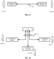
- Fig. 1A is a diagram schematically illustrating an example voice communication system where embodiments of the application can be applied.
- user A operates a communication terminal A
- user B operates a communication terminal B
- the communication terminals A and B are coupled through a data link 103.
- the data link 103 may be implemented as a point-to-point connection or a communication network.
- VAD Voice Activity Detection
- voice presence is decided in an audio block
- corresponding processing e.g., applying a gain suitable for voice
- the audio block is transmitted to another user's communication terminal A through the data link 103.
- corresponding processing e.g., applying a gain suitable for non-voice
- the audio block is transmitted to another user's communication terminal A through the data link 103.
- the other user's communication terminal receives the transmitted audio blocks and stores them to entries corresponding to the same time as the audio blocks in its jitter buffer, to eliminate transmission jitters. Audio blocks in the jitter buffer are fed through decoding and processing to reproduce them at the output transducer or transducers of the communication terminal. Reception of the simple information or nothing may cause corresponding empty entries in the jitter buffer.
- Fig. 1B is a diagram schematically illustrating another example voice communication system where embodiments of the application can be applied.
- a voice conference may be conducted among users.
- Fig. 1B user A operates a communication terminal A
- user B operates a communication terminal B
- user C operates a communication terminal C
- the communication terminals illustrated in Fig. 1B have the same function as those illustrated in Fig. 1A .
- the communication terminals A, B, and C are coupled to a server through a common data link 113 or separate data links 113.
- the data link 113 may be implemented as a point-to-point connection or a communication network.
- VAD is performed on audio blocks of the audio signal captured by the user's communication terminal.
- corresponding processing e.g., applying a gain suitable for voice
- corresponding processing e.g., applying a gain suitable for non-voice
- the server receives the transmitted audio blocks and stores them to entries corresponding to the same time as the audio blocks in its jitter buffers associated with the users respectively, to eliminate transmission jitters.
- Audio blocks corresponding to the same time in the jitter buffers are mixed into one audio block and the mixed audio block is transmitted to all users A, B, and C. Reception of the simple information or nothing may cause corresponding empty entries in the jitter buffers.
- the users' communication terminals receive the audio blocks from the server and store them to entries corresponding to the same time as the audio blocks in their jitter buffers, to eliminate transmission jitters.
- audio blocks in the jitter buffer are fed to a voice processor to reproduce them through the speaker system of the communication terminal.
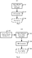
- a first embodiment of the present application provides an apparatus 200 for controlling a jitter buffer 206 as shown in Fig.2 .
- the apparatus comprises an inter-talkspurt delay jitter estimator 202 for estimating an offset value of the delay of a first frame in the current talkspurt with respect to the delay of a latest anchor frame in a previous talkspurt, and a jitter buffer controller 204 for adjusting a length of the jitter buffer 206 based on a long term length of the jitter buffer 206 for each frame and the offset value.
- the length (or size, or level) of the jitter buffer 206 may be adjusted based on the long term length of the jitter buffer (JB) 206 and the offset value (or jitter value) of the delay of the first frame in the current talkspurt.
- the long term length of the JB reflects a long term level of delay jitter in history audio signals
- the offset value of the delay of the first frame reflects the possible delay jitter of the current talkspurt.
- the apparatus for controlling the JB adjusts the length of the JB 206 based on both.
- jitter buffer is a "logical" jitter buffer storing audio frames. While depending on specific implementations, the physical jitter buffer may store any forms of packets or audio frames. Therefore, throughout the specification, the term “jitter buffer” shall be construed as including both jitter buffer actually storing audio frames and jitter buffer actually storing any forms of packets (blocks) which will be decoded into audio frames before being played out or being fed into any components where audio frames are necessary, and the decoding process will not be explicitly discussed in the present application although it does exist.
- the term "frame” shall be construed as including a real frame already decoded from a packet or still encoded in the packet, or a packet itself including one or more frames, or more than one frame encoded in a packet or already decoded from the packet.
- a processing involving a frame may also be construed as a processing involving a packet, or a processing involving simultaneously more than one frame contained in a packet.
- the long term length of the JB is conventionally available for each frame. It may be estimated with a long term length estimator 802 (see Fig.8 ) by computing a histogram of the past jitter values. Alternatively, the histogram can be replaced by a probability mass function (PMF) (see US patent application published as US20090003369A1 ). Once the histogram or PMF is calculated, the long term length can be estimated by setting a threshold such that the cumulative probability of the expected delay variation is less than this threshold.
- PMF probability mass function
- the offset value of the delay of the first frame is calculated with respect to the latest anchor frame in the last talkspurt.
- Anchor frame is conventionally used as a reference for estimating a delay jitter of a newly received frame within the same talkspurt.
- offset value is estimated. And thus the length of the JB may be adjusted upon the start of a new talkspurt by referring to the last talkspurt.
- the anchor frame in a talkspurt may be set with an anchor frame setting unit 402 ( Fig.4 ).
- an anchor frame setting unit 402 Fig.4
- it is difficult to measure an absolute one way delay requiring both sender and receiver timing information and clock synchronization.
- storing many packets in order to get minimum delay is not practical in a real time system like VoIP, and using too old an anchor frame may be subject to numerical issues and clock drift. Therefore, it is proposed to use the first frame of the talkspurt as the anchor and then keep updating it, so that a "local" minimum delay within one talkspurt may be used.
- Another problem arising from setting the first frame as the anchor frame is that the first frame might be in a delay spike, which would not be detected if using the first frame as the anchor. This could lead to inaccurate delay distribution estimation and over-estimation of jitter buffer length.
- Keeping updating the anchor frame within the talkspurt mentioned above may partly mitigate the problem, and the problem may be further mitigated through the cross-talkspurt use of the latest anchor frame in the last talkspurt or more latest anchor frames in several previous talkspurts as will be discussed later. In this way, a local minimum delay within a longer time period may be found and used.
- the apparatus for controlling a jitter buffer may further comprise an anchor frame setting unit 402 for initially setting the first frame in the current talkspurt as the anchor frame, and setting a newly received frame as the anchor frame when a delay jitter of the newly received frame meets a predefined condition.
- an anchor frame setting unit 402 for initially setting the first frame in the current talkspurt as the anchor frame, and setting a newly received frame as the anchor frame when a delay jitter of the newly received frame meets a predefined condition.
- the anchor frame may be updated in time and thus a timely-closer anchor frame may be used. For example, if the delay jitter of a new frame with respect to the present anchor frame is less than 0, that is, the new frame arrived earlier than expected, then the new frame may be used as new anchor frame. Or, for avoiding using too old an anchor frame, the new frame with zero delay jitter may also be used as the new anchor frame.
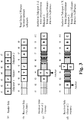
- Fig.3 there are two talkspurts 1 and 2 separated by a silence frame (shown as a block shadowed with slash lines).
- the frames X, Y, Z in Talkspurt 1 are sent at time t1, t2, t3 ( Fig.3(a) ) and would be received on the receiver side at time t3, t4, t5 with an overall delay (total delay with respect to the sending time) of two frame gaps (t1 and t2), assuming t i+1 -t i is a frame gap of 20ms and i is an integer( Fig.3(b) ).
- the first frame X would be set as the initial anchor frame.
- X may be maintained as the anchor frame, or either frame Y or Z may be updated as new anchor frame (not shown in Fig.3(b) ).
- frames X and Y arrive as expected based on the total delay but frame Z arrive 1 frame (frame gap) earlier than expected, taking frame X or Y as reference (anchor frame).
- frame Z is updated as the anchor frame since the jitter value is less than 0 (-1 frame).
- frames Y and Z are shown as arriving at the same time (t4 or t5, respectively).
- the meaning of the expression "at the same time” includes but is not limited to the exact literal meaning, and shall be construed as "within the same time gap/interval of a predefined granularity".
- the predefined granularity may be the time gap between two consecutively-sent frames/packets (such time gap may be referred to as frame gap), or network probing rate for checking packet arrivals , or processing time granularity, but is not limited thereto.
- frame gap e.g. we may quantize the arrival time by frame duration/gap, e.g. 20ms. That is, we represent time in integer number of packets.
- frame duration/gap e.g. 20ms. That is, we represent time in integer number of packets.
- time point when involving a specific time t i (i is integer) for a certain frame where it shall be understood as a time point, assuming for clarity that it indicates the time point when the frame starts on the sender side, or indicates the time point when the reception of the frame starts on the receiver side.
- the first frame X is initially set as anchor frame, with respect to which both frames Y and Z are further delayed.
- the delay jitter of frame Y is 2 frames and that of frame Z is 1 frame, and thus frame X is maintained as anchor frame until talkspurt 1 completes because the jitter value is greater than 0.
- the jitter value of a newly received frame with respect to the anchor frame may be estimated by an intra-talkspurt delay jitter estimator 502 (in variation 500 as shown in Fig.5 ).
- the intra-talkspurt delay jitter estimator 502 is configured to calculate, as the delay jitter, a difference between an actual reception time of the newly received frame and an expected reception time of the same newly received frame, the expected reception time being calculated with the present anchor frame as a reference.
- the delay jitter is measured in unit of time. Since the time gap (frame gap) between two consecutive frames without delay jitter is fixed (such as 20ms), the delay jitter (as well as delay) may also be measured in unit of frame. For example, we can say the delay jitter of frame Z is -1 frame, that is, frame Z arrives one frame earlier.
- the anchor frame will be constantly updated if the predefined condition is met.
- a latest anchor frame such as frame Z in Fig.3(c) or frame X in Fig.3(d) when talkspurt 1 finishes; and for the new talkspurt, there will be a new anchor frame, such as the first frame A in Fig.3 when talkspurt 2 starts.
- the offset value (jitter) of the delay of the first frame is calculated with respect to the latest anchor frame in the last talkspurt, thus the length of the JB may be adjusted upon the start of a new talkspurt by referring to the last talkspurt.
- the offset value of the delay of the first frame may be estimated in the inter-talkspurt delay jitter estimator 202 by means of a time difference estimator 2022 for calculating a time difference between the reception time of the latest anchor frame and the reception time of the first frame, and a frame number estimator 2024 for estimating an expected number of frames between the latest anchor frame and the first frame.
- the offset value may be calculated based on the time difference and an expected time difference obtained based on the expected number of frames.
- the expected number of frames may be determined based on sequence numbers of the latest anchor frame and the first frame and information regarding silence frames between the previous talkspurt and the current talkspurt, the information regarding silence frames being carried in at least one frame in at least one talkspurt in the previous talkspurt and the current talkspurt.
- DTX Discontinuous Transmission
- the number of non-silence frames between two non-silence frames may be deduced from the sequence numbers of the two non-silence frames because non-silence frames are sequentially numbered regardless whether the two non-silence frames belong to the same talkspurt.
- the number of silence frames lapsed since the end of the last talkspurt cannot be deduced directly from RTP (Real-time Transport Protocol) sequence number of RTP packets/frames, because the RTP packet sequence number will not increment for silence packets/frames.
- RTP Real-time Transport Protocol
- the sequence number of frame A directly follows the sequence number of frame Z, thus it is impossible to deduce from the sequence numbers of frames Z and A the number of silence frames between frames Z and A.
- DTX mode and RTP format are just examples and the present application is not limited thereto.
- timestamp information may be embedded in all the frames as that in the standard RTP frame format, or only embedded in the last frame of the previous talkspurt and the first frame of the current talkspurt.
- timestamp information may be embedded in all frames, or only in frames Z and A. In either situation, the timestamp information in frames Z and A is enough for deducing the number of silence frames.
- the timestamp embedded in frame Z will be its sending time t3
- the timestamp embedded in frame A will be its sending time t5.
- the information regarding silence frames may comprise the number of the silence frames, the number being embedded in the first frame of the current talkspurt.
- the information regarding silence frames may comprise timestamps in the last frame of the previous talkspurt and the first frame in the current talkspurt.
- G (such as 20ms) be the expected time gap (frame gap) between consecutive frames without jitter
- the expected reception time difference between the latest anchor frame of the last talkspurt and the first frame of the current talkspurt will be Ntotal*G.
- the delay jitter so calculated is measured in unit of time.
- the latest anchor frame in the last talkspurt is used.
- the last talkspurt is a previous talkspurt immediately previous to the current talkspurt.
- the offset value may be estimated with respect to a previous talkspurt not immediately adjacent to the current talkspurt, and by referring to the description hereinbefore it is easy to anticipate how to estimate the offset value.
- the apparatus for controlling a jitter buffer may further comprise an offset buffer 702 for storing at least one earlier offset value of at least one first frame in at least one earlier talkspurt, and the inter-talkspurt delay jitter estimator 202 may be configured to adjust the offset value of the delay of the first frame in the current talkspurt based on an average or weighted average of the at least one earlier offset valuee, or adopt the largest offset value among the present offset value and the at least one earlier offset value.
- the instant length of the jitter buffer may be adjusted based on the long term length of the jitter buffer and the offset value as determined in the first embodiment. Such adjustment may be implemented in any proper way in so far as both the long term length and the offset value are considered.
- the long term length B j (n) of the jitter buffer for frame n in talkspurt j can be estimated by computing a statistical distribution of history delay jitter values, such as a histogram of the past jitter values.
- a delay jitter threshold may be selected so that the cumulative probability of the delay jitter values lower than the delay jitter threshold meets the requirement in practice. For example, if a voice communication application requires the frame loss rate shall be lower than 5%, then we can set the delay jitter threshold so that the cumulative probability of the delay jitter values lower than the delay jitter threshold is equal or greater than 95%.
- the frame loss rate will be equal to or lower than 5% (although in the present application, the long term length is not necessarily directly adopted as the instant jitter buffer length).
- the histogram can be replaced by a probability mass function (PMF) (see US patent application published as US20090003369A1 ).
- the long term length estimator 802 since the long term length is determined based on jitter values in the history, the history data will be updated only when a new frame is received. Therefore, the estimation of the long term length of the long term length estimator 802 will be triggered only when a new frame is received. At a particular time, we may or may not receive a frame to update the long term length. Therefore, in the symbol of the long term length B j (n), we ignore the time index t.
- the long term length B j (n) may be firstly adjusted by a long term length adjustor 902 with the offset value d j (0) discussed in the first embodiment.
- the basic idea of the adjustment is properly decreasing the long term length if the offset value is greater than 0.
- the decrease of the long term length may be realized in any way.
- B' j (n) is an adjusted version of the long term length B j (n), and d j (0) should be not less than 0.
- the operation ⁇ x ⁇ has the same meaning as in the first embodiment, and may be replaced with rounding function or ceiling function.
- the offset is greater than the long term length, it means the jitter has exhausted the long term length, and the packet should be played out immediately. While in the present application, according to the formula (1), we still give the packet a smaller buffer length (B j (n)/2) to avoid possible packet loss.
- the denominator "2" is just an example and it may be any other value greater than 1.
- the long term length adjustor 902 may be configured to fade the offset value with time. That is, d j (0) calculated in the first embodiment may just serve as an initial offset used in the formula (1), and with the increasing of the index n (as well as lapse of time), that is, every time a new frame is received, the value of d j (0) may be decreased, thus the effect of d j (0) upon the long term length may be faded with time.
- the long term length estimator may reset the long term length to a predefined initial value, and reset the history delay jitter values. That is, the history jitter values up to the last talkspurt will be discarded and the history jitter values will be re-accumulated from the start of the new talkspurt. In this way, we can reset the long term length (and thus the length of the jitter buffer) to a normal level, since the last talkspurt probably is an abnormal one.
- the solution of the second embodiment may be based on the first embodiment, but it can also be a solution independent from the first embodiment. Therefore, as shown in Fig.8 and Fig.9 , those components shown in dash lines may be omitted.
- the jitter buffer length may be adjusted via adjustment to the long term length of the jitter buffer.
- a simple way is directly using the long term length as the instant length of the jitter buffer for each frame.
- a more specific adjustment to the jitter buffer length, or strictly speaking, the initial length of the jitter buffer for a new talkspurt, is introduced.
- the third embodiment is also shown in Fig.8 and Fig.9 , especially by the dashed line arrow directing from the jitter buffer 206 to the JB controller 204.
- the jitter buffer controller 204 may be configured to set the length of the jitter buffer 206 for the first frame of the current talkspurt based on the long term length for the first frame and the number of frames received at the same time with the first frame.
- L j t 0 B ′ j n 0 + N t 0 + C
- L j (t0) is the instant length of the jitter buffer at the time t0 of the first frame n0 in the current talkspurt
- B' j (n0) is the adjusted long term length for the first frame n0
- N(t0) is the number of frames received at t0, that is, at the same time as the first frame n0
- C is a predefined constant integer.
- the expression "at the same time” shall be construed as mentioned before. That is, N(t0) actually is the number of frames received in the same time gap as the first frame n0.
- N(t0) may or may not take the first frame itself into account, and the difference so introduced may be compensated by the constant C.
- the number of not-yet-played out frames of the last talkspurt (that is the jitter buffer length still used by the last talkspurt) is greater than the long term length for the first frame of the current talkspurt, it means not all of those frames of the last talkspurt can be played out if the first frame of the current talkspurt must be played out in time based on the long term length for the first frame.
- the jitter buffer controller 204 may be configured to, if the jitter buffer length still used by the last talkspurt is greater than the long term length and the first frame of the new talkspurt has arrived, drop some of the frames of the last talkspurt so that the frames of the last talkspurt occupy only the long term length of the jitter buffer.
- the JB length is 5 frames.
- 3 frames (1 to 3, including the first frame 1) of a new talkspurt arrive and the estimated (and possibly adjusted) long term length of the jitter buffer for the first frame is 2. That means the long term length (2) for the first frame 1 plus the number (3) of the arrived frames of the new talkspurt will occupy a JB length of 5 frames.
- the first frame 1 of the current talkspurt must wait for 4 frames (n-3 to n, and the frame n-4 has been played out), which deviate from the long term length of 2 frames too much. Therefore, 2 frames of the last talkspurt must be dropped to let the first frame of the current talkspurt be played out timely.
- frames n-1 and n are dropped, that is, the last frames are dropped.
- other dropping scheme may be adopted, which will be discussed later.
- the instant length of the jitter buffer may be adaptively changed from frame to frame.
- the jitter buffer controller 204 may be further configured to adjust the present length of the jitter buffer toward the long term length. Such adjustment may be implemented by calculating a weighted average of the long term length and the present length.
- L f , j n L a , j n + ⁇ B ′ j n ⁇ L a , j n
- B' j (n) is the long term length of the jitter buffer for the current frame n in talkspurt j, which has been adjusted with the offset value as described in previous embodiments and their variants
- L a,j (n) is the actual jitter buffer length for the current frame n
- L f,j (n) is the final jitter buffer length for the current frame n
- ⁇ is the weight, which may be regarded as a time constant controlling how much smoothing is applied.
- the index n is used because the operation is executed from frame to frame.
- index n is still used in the term B' j (n) because B' j (n) is updated on a frame-basis as discussed hereinbefore.
- the current time t does not necessarily correspond to the current frame n in a one-to-one manner, because the time t is always ticking forward while the index n will not necessarily increase so smoothly due to the delay jitter of frames.
- the jitter buffer controller may be configured so that the weight of the long term length is greater when the long term length is greater than the present length, and is smaller when the long term length is smaller than the present length.
- B' j (n) is used.
- B j (n) may be used instead.
- the initial value of L a,j (t) in the current talkspurt that is L a,j (t0)
- L a,j (t0) may or may not adopt the value L j (t0) discussed in the third/fourth embodiment and their variants. That is to say, the fifth embodiment and its variations may be combined together with the other embodiments and their variations discussed in this application, and may also be independent therefrom.
- Jitter is the delay fluctuation of the arrived frames.
- the embodiments and variations discussed hereinbefore predict the jitter buffer length based on jitters of past frames. When there is a large jitter, the buffer algorithm cannot be updated appropriately since the instantaneous jitter is not yet seen by the buffer algorithm. Without adjusting the JB length, a large jitter will cause a large amount of frame losses.
- the apparatus 1100 for controlling a jitter buffer 206 may comprise a jitter buffer monitor 1102 for monitoring occupancy of the jitter buffer 206, and wherein the jitter buffer controller 204 is further configured to increase the length of the jitter buffer 206 in response to the occupancy meeting a predefined condition.
- One embodiment is to check the occurrence number of consecutive single frame buffer occupancy. For example when there are two consecutive single-frame buffer occupancies, it may indicate that a rise of jitter may have occurred and the current buffer length is not long enough to meet the requirement. Therefore an extra one frame delay may be added to the current buffer length.
- the jitter buffer controller 204 may be configured to increase the length of the jitter buffer 206 where an occupancy less than a predetermined threshold has consecutively occurred for a predetermined times.
- pre-emptive expansion occurs when there are still frames available in the buffer, it provides the benefit of using frame interpolation instead of single-side frame extrapolation as in conventional approaches. It is known to those skilled in the art that frame interpolation can often produce better result than frame extrapolation. Pre-emptive expansion also helps spread the signal process which often causes distortion in the output.
- the jitter buffer length cannot be increased too fast and/or unlimitedly.
- the jitter buffer controller 204 may be configured to increase the length of the jitter buffer by one frame each time the condition is met.
- the apparatus for controlling a jitter buffer may further comprise a signal content monitor 1104 for monitoring the content of the audio signal, and wherein the jitter buffer controller 204 is configured not to increase the length of the jitter buffer where the content of the audio signal is not appropriate for frame insertion.
- a specific example is transient signal area. Frame insertion at the transient signal area often generates artifacts. Therefore, the signal content monitor 1104 may be configured to monitor the transient state of the audio signal, and the jitter buffer controller 204 may be configured not to increase the length of the jitter buffer in transient signal area.
- the jitter buffer controller may be configured to not increase the length of the jitter buffer where the present jitter buffer length exceeds a predetermined threshold.
- Past signal processing frequency may also be referred to, i.e. we may stop frame insertion if this has been done a few times already. Therefore, in a variation 1200 as shown in Fig.12 , the apparatus for controlling a jitter buffer may further comprise a counter 1202 for counting frame insertions within the present talkspurt, wherein the jitter buffer controller 204 may be configured to not increase the length of the jitter buffer where the number of frame insertions within the present talkspurt exceeds a predetermined threshold.
- the sixth embodiment and its variations may be implemented on the basis of any one or more of the other embodiments discussed hereinbefore, or may be implemented independent from the other embodiments. Just as shown in Fig.11 and Fig.12 , all the components shown in dashed lines may be omitted or may be combined with the present embodiment in any combination.
- the instant jitter buffer length may be increased or shrunk in various situations.
- the target jitter buffer length (the calculated jitter buffer length) equals to the present actual buffer length
- the head frame of the jitter buffer is pushed out and played.
- an expansion is performed.
- the target jitter buffer length is smaller than the actual buffer length, a buffer shrink is performed.
- Increase of the jitter buffer length may be realized through frame interpolation when a frame is available in the jitter buffer, or frame extrapolation when no frames are available in the jitter buffer.
- Frame interpolation means adding a frame before an available frame in the jitter buffer.
- the added frame may be an empty frame, a synthesized frame or a duplicate of the present playout frame or a future (not yet played out) frame in the jitter buffer.
- Frame extrapolation means adding a frame at the end of the jitter buffer. When there is no available frame in the jitter buffer, it means the added frame is after the latest playout frame. Similar to interpolation, an extrapolated frame may also be an empty frame, a synthesized frame or a duplicate of the latest playout frame.
- Decrease of the jitter buffer length may be realized through dropping frames in the jitter buffer.
- the dropped frame may be at the head or end of the jitter buffer, or in the middle of the jitter buffer.
- the jitter buffer controller may be configured to decrease the jitter buffer length through interleaved removal of frames in the jitter buffer.
- the removed frames may be selected randomly or according to predetermined pattern, such as removing one frame from every two or three frames.
- the apparatus for controlling the jitter buffer may further comprise a frame evaluator for evaluating the importance of frames in the jitter buffer, wherein the jitter buffer controller is configured to decrease the jitter buffer length by dropping those least important frames.
- the importance of the frame may be evaluated based on signal energy or spectral flux of frames, those frames with relatively low signal energy or low spectral flux being determined as relatively less important frames.
- Another factor that may be used as the standard for dropping frames is periodicity. If the signal is highly periodic, it will make time scaling (expansion or compression) less prone to artifacts. Therefore, those segments of an audio signal that are highly periodic may be subject to interleaved removal; while the other segments may be subject to other form of frame dropping if necessary, such as dropping frames of lower energy.
- inter-talkspurt delay jitter offset value
- jitter buffer length Fig.2
- anchor frame Fig.4
- estimating intra-talkspurt delay jitter and updating anchor frame Fig.3 , Fig.5
- estimating inter-talkspurt delay jitter offset value
- Fig.6 estimating inter-talkspurt delay jitter
- Fig.7 multiple offset values to adjust the jitter buffer length
- Fig.8 estimating long term jitter buffer length
- Fig.8 estimating long term jitter buffer length
- Fig.8 determining the jitter buffer length based on long term jitter buffer length and the offset value( Fig.8 )
- setting and adapting instant jitter buffer length based on the long term jitter buffer length and first received frames ( Fig.10 ); (9) adjusting the long term jitter buffer length with the offset value ( Fig.9 ); (10) intra-talkspurt adaption of the jitter buffer length toward
- Fig. 13 is a block diagram illustrating an exemplary system for implementing the aspects of the present application.
- a central processing unit (CPU) 1301 performs various processes in accordance with a program stored in a read only memory (ROM) 1302 or a program loaded from a storage section 1308 to a random access memory (RAM) 1303.
- ROM read only memory
- RAM random access memory
- data required when the CPU 1301 performs the various processes or the like are also stored as required.
- the CPU 1301, the ROM 1302 and the RAM 1303 are connected to one another via a bus 1304.
- An input / output interface 1305 is also connected to the bus 1304.
- the following components are connected to the input/output interface 1305: an input section 1306 including a keyboard, a mouse, or the like; an output section 1307 including a display such as a cathode ray tube (CRT), a liquid crystal display (LCD), or the like, and a loudspeaker or the like; the storage section 1308 including a hard disk or the like ; and a communication section 1309 including a network interface card such as a LAN card, a modem, or the like.
- the communication section 1309 performs a communication process via the network such as the internet.
- a drive 1310 is also connected to the input/output interface 1305 as required.
- a removable medium 1311 such as a magnetic disk, an optical disk, a magneto-optical disk, a semiconductor memory, or the like, is mounted on the drive 1310 as required, so that a computer program read there from is installed into the storage section 1308 as required.
- the program that constitutes the software is installed from the network such as the internet or the storage medium such as the removable medium 1311.
- Figs. 14-18 show several threads among others.
- Fig. 14 is a thread 1400 for setting and updating of anchor frames.
- Fig. 15 is a thread 1500 for estimating the long term length of the jitter buffer.
- Fig. 16 is a thread 1600 for estimating the cross-talkspurt offset and adjusting the long term length of the jitter buffer.
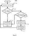
- Fig. 17 is a thread 1700 for updating the jitter buffer length.
- Fig. 14 is a thread 1400 for setting and updating of anchor frames.
- Fig. 15 is a thread 1500 for estimating the long term length of the jitter buffer.
- Fig. 16 is a thread 1600 for estimating the cross-talkspurt offset and adjusting the long term length of the jitter buffer.
- Fig. 17 is a thread 1700 for updating the jitter buffer length.
- Fig. 14 is a thread 1400 for setting and updating of anchor frames.
- Fig. 15 is a thread 1500 for estimating the long term
- the embodiments of the methods for controlling a jitter buffer according to the present application may be only a part of one of the threads shown in Figs. 14-18 , or may be a solution bridging different parts of different threads. For those details not illustrated in Figs. 14-18 and/or not described below, reference may be made to the description of the apparatus for controlling a jitter buffer.
- a method for controlling a jitter buffer is provided.
- an offset value of the delay of a first frame in the current talkspurt is estimated with respect to the delay of a latest anchor frame in a previous talkspurt, and is used to, together with a long term length of the jitter buffer for each frame, to adjust a length of the jitter buffer.
- a positive offset value means the first frame in a new talkspurt probably is delayed too much, that is, has a positive jitter.
- the long term length of the jitter buffer may be increased to accommodate possibly greater jitter, or may be decreased to avoid the delay introduced by the jitter buffer is too long.
- Fig.14 shows the setting of the anchor frame. Initially, that is when receiving a new frame (operation 1402) and the new frame is a first frame in a new talkspurt ("Yes” in operation 1404), then the frame is set as anchor frame (operation 1406). Then, newly received frame after the first frame (“No” in operation 1404) may be set as the anchor frame if it meets a predefined condition ("Yes” in operation 1408). That is, the anchor frame may be updated to be the newly received frame.
- the predefined condition may be about the delay jitter of the newly received frame. If the delay jitter is less than 0, or equal to 0, then the newly received frame may be set as new anchor frame. In this way, it is ensured that finally a local minimum delay may be located within each talkspurt, thus avoiding the jitter buffer length becomes too long.
- the delay jitter may be calculated as a difference between an actual reception time of the newly received frame and an expected reception time of the same newly received frame. The expected reception time is calculated with the present anchor frame as a reference.
- the offset value mentioned above may be estimated with respect to the latest anchor frame in a previous talkspurt immediately previous to the current talkspurt, or a previous talkspurt not immediately adjacent to the current talkspurt. In this way, some previous talkspurts which are too short or too bad in quality may be neglected, and, similar to the estimation of the intra-spurt delay jitter, it can be ensured that the reference (anchor frame in a previous talkspurt) itself can have relatively small jitter.
- the offset value of the delay of the first frame in the current talkspurt may be adjusted based on an average or weighted average of at least one earlier offset value, or adopt the largest offset value among the present offset value and the at least one earlier offset value.
- the offset value may be calculated as a time difference between the following two: a real time difference between the reception time of the latest anchor frame and the reception time of the first frame, and an corresponding expected time difference.
- the expected time difference may be obtained based on an expected number of frames between the latest anchor frame and the first frame.
- the expected number of frames may be obtained firstly based on sequence numbers of the latest anchor frame and the first frame. Also, information regarding silence frames between the previous talkspurt and the current talkspurt may be retrieved from at least one frame in at least one talkspurt in the previous talkspurt and the current talkspurt.
- the information regarding silence frames may include the number of the silence frames, the number being embedded in the first frame of the current talkspurt.
- the information regarding silence frames may comprise timestamps in the last frame of the previous talkspurt and the first frame in the current talkspurt.
- the method may further comprise estimating the long term length for each frame by calculating a statistic distribution of history delay jitter values (operation 1512 or operation 1514 in Fig.15 ), such as a histogram or a probability mass function (PMF) of the past jitter values. Since the long term length is calculated based on delay jitter values of past frames, the calculation or updating thereof may be triggered by reception of a new frame (operation 1502 in Fig.15 ).
- a statistic distribution of history delay jitter values operation 1512 or operation 1514 in Fig.15
- PMF probability mass function
- the long term length at the end of the last talkspurt is not greater than a predefined threshold Th1 ("No" in operation 1508), the long term length will not be reset and will be continued to be estimated based on history jitter values since beginning or the last resetting.
- the long term length may be subject to an adjustment based on the offset value, and all the operations relating to the long term length discussed above are based on the adjusted value of the long term length. For example, when the offset value is greater than zero ("Yes" in operation 1608), the long term length may be decreased (operation 1610). In Fig.16 it is shown that no operations will be performed when the offset is not greater than 0, but the present application is not limited thereto. For example, depending on requirements in practice, sometimes it may be acceptable to increase the long term length when the offset is not greater than 0.
- the offset value is estimated (operation 1606) for the first frame in a new talkspurt ("Yes” in operation 1604).
- the corresponding long term length for each frame may also be adjusted (operation 1610).
- the offset value may fade gradually (operation 1612), since the farther away is the subsequent frame from the first frame, the smaller is the effect of the offset of the first frame.
- the operation of adjusting the length of the jitter buffer may comprise, for the first frame of the current talkspurt (operation 1702 in Fig.17 ) setting the length of the jitter buffer based on the long term length for the first frame and the number of frames received at the same time with the first frame (operation 1708), so as to ensuring the delay time of the first frame and the buffering space for the other frames already received.
- the jitter buffer length still used by the last talkspurt that is the present actual jitter buffer length
- some of the frames of the last talkspurt may be dropped (operation 1706) so that the frames of the last talkspurt occupy only the long term length of the jitter buffer.
- the present jitter buffer length is not greater than the long term length ("No" in operation 1704)
- the frames (if any) of the last talkspurt have enough time to be played out before the first frame of the new talkspurt is played out. The excessive time will be occupied by empty frames in the jitter buffer before the first frame.
- the jitter buffer length may be further adjusted toward the long term length (operation 1714).
- the "time interval” may be the "processing time granularity" as mentioned before, and the word “toward” means the jitter buffer length is adjusted to be closer to the long term length, but not necessarily become equal to the long term length at once.
- the weight of the long term length may be greater so that the jitter buffer length may be increased quickly to the long term length because the situation where the long term length is great generally means the delay is severe and longer jitter buffer is needed to prevent frame loss.
- the weight may be smaller, because in such a situation, the purpose of the adjustment is to release unnecessary length of the jitter buffer so as to shorten the delay time, which is not so urgent as preventing frame loss. Nevertheless, sometimes we may directly set the long term length as the length of the jitter buffer for each frame.
- the method may further comprise pre-emptively expanding the jitter buffer (operation 1718 in Fig.17 ) where necessary ("Yes" in operation 1716), so as to make ready for possible rise of delay jitter.
- Such possible rise of delay jitter may be reflected by continuous low occupancy of the jitter buffer, meaning that the receiving of future frames are becoming slower. Therefore, we may monitor the occupancy of the jitter buffer (operation 1802 in Fig.18 ), and increase the length of the jitter buffer (operation 1814) in response to the occupancy meeting a predefined condition, such as continuous low occupancy ("Yes" in operation 1804).
- a predefined condition is the occupancy is less than a predetermined threshold consecutively for a predetermined times, such as a single-frame occupancy has consecutively occurred twice.
- the pre-emptive expansion is based on a prediction, it is better to be cautious so that the jitter buffer length will not be increased too much and too quickly. Therefore we may pose some limitations on the pre-emptive expansion of the jitter buffer.
- Another criterion is times of frame insertions.
- any combination of the seventh to tenth embodiment and their variations are practical on one hand; and on the other hand, every aspect of the embodiments and their variations may be separate solutions.
- the invention may suitably comprise, consist of, or consist essentially of, any of element (the various parts or features of the invention and their equivalents as described herein, currently existing, and/or as subsequently developed.
- the present invention illustratively disclosed herein may be practiced in the absence of any element, whether or not specifically disclosed herein.
- numerous modifications and variations of the present invention are possible in light of the above teachings. It is therefore to be understood that within the scope of the appended claims, the invention may be practiced otherwise than as specifically described herein.
- EEEs Enumerated Example Embodiments
Landscapes
- Engineering & Computer Science (AREA)
- Computer Networks & Wireless Communication (AREA)
- Signal Processing (AREA)
- Power Engineering (AREA)
- Transportation (AREA)
- Mechanical Engineering (AREA)
- Multimedia (AREA)
- Quality & Reliability (AREA)
- Computer Security & Cryptography (AREA)
- Environmental & Geological Engineering (AREA)
- Data Exchanges In Wide-Area Networks (AREA)
- Communication Control (AREA)
Claims (15)
- Vorrichtung zum Steuern eines Jitterpuffers (206), umfassend:eine Schätzeinrichtung (202) für den Laufzeitjitter zwischen Sprechperioden zum Schätzen eines Abweichungswerts der Laufzeit eines ersten Frames in der aktuellen Sprechperiode in Bezug auf die Laufzeit eines letzten Bezugsframes in einer vorhergehenden Sprechperiode; undeine Jitterpuffer-Steuerung (204) zum Einstellen einer Länge des Jitterpuffers (206) auf der Grundlage des Abweichungswerts und einer geschätzten langfristigen Länge des Jitterpuffers, wobei die Schätzung der geschätzten langfristigen Länge des Jitterpuffers durch den Empfang eines neuen Frames ausgelöst wird.
- Vorrichtung zum Steuern eines Jitterpuffers nach Anspruch 1, weiter umfassend eine Bezugsframe-Einstelleinheit zum anfänglichen Einstellen des ersten Frames in der aktuellen Sprechperiode als den Bezugsframe und Einstellen eines neu empfangenen Frames als den Bezugsframe, wenn ein Laufzeitjitter des neu empfangenen Frames eine vordefinierte Bedingung erfüllt.
- Vorrichtung zum Steuern eines Jitterpuffers nach Anspruch 2, wobei die vorbestimmte Bedingung darin besteht, dass der Laufzeitjitter gleich oder weniger als 0 ist.
- Vorrichtung zum Steuern eines Jitterpuffers nach Anspruch 1, weiter umfassend eine Schätzeinrichtung für den Laufzeitjitter innerhalb einer Sprechperiode zum Berechnen, als Laufzeitjitter, einer Differenz zwischen einer tatsächlichen Empfangszeit des neu empfangenen Frames und einer erwarteten Empfangszeit desselben neu empfangenen Frames, wobei die erwartete Empfangszeit mit dem aktuellen Bezugsframe als Bezugspunkt berechnet wird.
- Vorrichtung zum Steuern eines Jitterpuffers nach Anspruch 1, wobei die Schätzeinrichtung für den Laufzeitjitter zwischen Sprechperioden dafür konfiguriert ist, den Abweichungswert der Laufzeit des ersten Frames in der aktuellen Sprechperiode in Bezug auf die Laufzeit des letzten Bezugsframes in einer vorhergehenden Sprechperiode unmittelbar vor der aktuellen Sprechperiode zu schätzen.
- Vorrichtung zum Steuern eines Jitterpuffers nach Anspruch 5, wobei die Schätzeinrichtung für den Laufzeitjitter zwischen Sprechperioden umfasst:eine Zeitdifferenz-Schätzeinrichtung zum Berechnen einer Zeitdifferenz zwischen der Empfangszeit des letzten Bezugsframes und der Empfangszeit des ersten Frames, undeine Frameanzahl-Schätzeinrichtung zum Schätzen einer erwarteten Anzahl von Frames zwischen dem letzten Bezugsframe und dem ersten Frame; und wobeidie Schätzeinrichtung für den Laufzeitjitter zwischen Sprechperioden dafür konfiguriert ist, den Abweichungswert auf der Grundlage der Zeitdifferenz und einer erwarteten Zeitdifferenz, die auf der Grundlage der erwarteten Anzahl von Frames erhalten wird, zu schätzen.
- Vorrichtung zum Steuern eines Jitterpuffers nach Anspruch 1, weiter umfassend einen Abweichungspuffer zum Speichern von mindestens einem früheren Abweichungswert mindestens eines ersten Frames in mindestens einer früheren Sprechperiode, wobei die Schätzeinrichtung für den Laufzeitjitter zwischen Sprechperioden dafür konfiguriert ist, den Abweichungswert der Laufzeit des ersten Frames in der aktuellen Sprechperiode auf der Grundlage eines Mittelwerts oder gewichteten Mittelwerts des mindestens einen früheren Abweichungswerts einzustellen oder den größten Abweichungswert aus dem aktuellen Abweichungswert und dem mindestens einen früheren Abweichungswert anzunehmen.
- Vorrichtung zum Steuern eines Jitterpuffers nach Anspruch 1, weiter umfassend eine Schätzeinrichtung für die langfristige Länge zum Schätzen der geschätzten langfristigen Länge durch Berechnen einer statistischen Verteilung von Laufzeitjitter-Werten im Verlauf.
- Verfahren zum Steuern eines Jitterpuffers (206), umfassend:Schätzen (1604) eines Abweichungswerts der Laufzeit eines ersten Frames in der aktuellen Sprechperiode in Bezug auf die Laufzeit eines letzten Bezugsframes in einer vorhergehenden Sprechperiode; undEinstellen einer Länge des Jitterpuffers auf der Grundlage des Abweichungswerts und einer geschätzten langfristigen Länge des Jitterpuffers, wobei die Schätzung (1512, 1514) der geschätzten langfristigen Länge des Jitterpuffers durch den Empfang (1502) eines neuen Frames ausgelöst wird.
- Verfahren zum Steuern eines Jitterpuffers nach Anspruch 9, weiter umfassend anfängliches Einstellen des ersten Frames in der aktuellen Sprechperiode als den Bezugsframe und Einstellen eines neu empfangenen Frames als den Bezugsframe, wenn ein Laufzeitjitter des neu empfangenen Frames eine vordefinierte Bedingung erfüllt.
- Verfahren zum Steuern eines Jitterpuffers nach Anspruch 10, wobei die vorbestimmte Bedingung darin besteht, dass der Laufzeitjitter gleich oder weniger als 0 ist.
- Verfahren zum Steuern eines Jitterpuffers nach Anspruch 9, weiter umfassend Berechnen, als Laufzeitjitter, einer Differenz zwischen einer tatsächlichen Empfangszeit des neu empfangenen Frames und einer erwarteten Empfangszeit desselben neu empfangenen Frames, wobei die erwartete Empfangszeit mit dem aktuellen Bezugsframe als Bezugspunkt berechnet wird.
- Verfahren zum Steuern eines Jitterpuffers nach Anspruch 9, wobei der Vorgang des Schätzens des Abweichungswerts ein Schätzen des Abweichungswerts der Laufzeit des ersten Frames in der aktuellen Sprechperiode in Bezug auf die Laufzeit des letzten Bezugsframes in einer vorhergehenden Sprechperiode unmittelbar vor der aktuellen Sprechperiode umfasst.
- Verfahren zum Steuern eines Jitterpuffers nach Anspruch 13, wobei der Vorgang des Schätzens des Abweichungswerts umfasst:Berechnen einer Zeitdifferenz zwischen der Empfangszeit des letzten Bezugsframes und der Empfangszeit des ersten Frames;Schätzen einer erwarteten Anzahl von Frames zwischen dem letzten Bezugsframe und dem ersten Frame; undSchätzen des Abweichungswerts auf der Grundlage der Zeitdifferenz und einer erwarteten Zeitdifferenz, die auf der Grundlage der erwarteten Anzahl von Frames erhalten wird.
- Computerlesbares Medium mit darauf verkörpertem computerlesbarem Programmcode, der beim Ausführen durch einen oder mehrere Prozessoren einer Vorrichtung zum Steuern eines Jitterpuffers die Vorrichtung veranlasst, das Verfahren nach einem der Ansprüche 9 bis 14 durchzuführen.
Applications Claiming Priority (3)
| Application Number | Priority Date | Filing Date | Title |
|---|---|---|---|
| CN201210560747.3A CN103888381A (zh) | 2012-12-20 | 2012-12-20 | 用于控制抖动缓冲器的装置和方法 |
| US201361759023P | 2013-01-31 | 2013-01-31 | |
| PCT/US2013/076387 WO2014100331A1 (en) | 2012-12-20 | 2013-12-19 | Apparatus and methods for controlling jitter buffer |
Related Child Applications (1)
| Application Number | Title | Priority Date | Filing Date |
|---|---|---|---|
| EP18214112.7 Division-Into | 2018-12-19 |
Publications (2)
| Publication Number | Publication Date |
|---|---|
| EP2936770A1 EP2936770A1 (de) | 2015-10-28 |
| EP2936770B1 true EP2936770B1 (de) | 2019-02-06 |
Family
ID=50957105
Family Applications (1)
| Application Number | Title | Priority Date | Filing Date |
|---|---|---|---|
| EP13818147.4A Active EP2936770B1 (de) | 2012-12-20 | 2013-12-19 | Vorrichtung und verfahren zur steuerung eines jitterpuffers |
Country Status (6)
| Country | Link |
|---|---|
| US (2) | US10560393B2 (de) |
| EP (1) | EP2936770B1 (de) |
| CN (1) | CN103888381A (de) |
| ES (1) | ES2714525T3 (de) |
| HK (1) | HK1217141A1 (de) |
| WO (1) | WO2014100331A1 (de) |
Families Citing this family (26)
| Publication number | Priority date | Publication date | Assignee | Title |
|---|---|---|---|---|
| CN104469255A (zh) | 2013-09-16 | 2015-03-25 | 杜比实验室特许公司 | 改进的音频或视频会议 |
| US9882818B2 (en) * | 2013-09-30 | 2018-01-30 | Apple Inc. | Adjusting a jitter buffer based on inter arrival jitter |
| CN103594103B (zh) * | 2013-11-15 | 2017-04-05 | 腾讯科技(成都)有限公司 | 音频处理方法及相关装置 |
| CN105099949A (zh) * | 2014-04-16 | 2015-11-25 | 杜比实验室特许公司 | 基于对延迟抖动和对话动态的监视的抖动缓冲器控制 |
| KR102422794B1 (ko) * | 2015-09-04 | 2022-07-20 | 삼성전자주식회사 | 재생지연 조절 방법 및 장치와 시간축 변형방법 및 장치 |
| US9749178B2 (en) | 2015-09-18 | 2017-08-29 | Whatsapp Inc. | Techniques to dynamically configure target bitrate for streaming network connections |
| US10412779B2 (en) * | 2015-09-18 | 2019-09-10 | Whatsapp Inc. | Techniques to dynamically configure jitter buffer sizing |
| EP3357197B1 (de) | 2015-09-29 | 2019-07-24 | Dolby Laboratories Licensing Corporation | Verfahren und system zur handhabung von heterogenem jitter |
| CN108141793B (zh) | 2015-10-13 | 2021-07-09 | 三星电子株式会社 | 用于提供基于单播的多媒体服务的方法和装置 |
| CN105939289B (zh) * | 2015-12-21 | 2019-03-12 | 小米科技有限责任公司 | 网络抖动处理方法、装置和终端设备 |
| US9929928B1 (en) * | 2015-12-24 | 2018-03-27 | Microsemi Solutions (U.S.), Inc. | Packet transmitter and method for timestamping packets |
| US20170187635A1 (en) * | 2015-12-28 | 2017-06-29 | Qualcomm Incorporated | System and method of jitter buffer management |
| CN105554019B (zh) * | 2016-01-08 | 2018-07-24 | 全时云商务服务股份有限公司 | 一种音频去抖动系统和方法 |
| DE112016006564B4 (de) * | 2016-03-10 | 2025-09-04 | Mitsubishi Electric Corporation | Empfänger und Ereigniserfassungszeitpunkt-Schätzungsverfahren |
| US10686897B2 (en) | 2016-06-27 | 2020-06-16 | Sennheiser Electronic Gmbh & Co. Kg | Method and system for transmission and low-latency real-time output and/or processing of an audio data stream |
| GB201614356D0 (en) | 2016-08-23 | 2016-10-05 | Microsoft Technology Licensing Llc | Media buffering |
| KR102532645B1 (ko) * | 2016-09-20 | 2023-05-15 | 삼성전자 주식회사 | 적응적 스트리밍 서비스에서 스트리밍 어플리케이케이션으로 데이터를 제공하는 방법 및 장치 |
| US10454811B2 (en) | 2017-04-07 | 2019-10-22 | Qualcomm Incorporated | Apparatus and method for de-jitter buffer delay adjustment |
| CN107566889B (zh) * | 2017-09-15 | 2020-06-16 | 深圳国微技术有限公司 | 音频流流速误差处理方法、装置、计算机装置及计算机可读存储介质 |
| GB201720612D0 (en) * | 2017-12-11 | 2018-01-24 | Nordic Semiconductor Asa | Radio communications |
| CN109996286A (zh) * | 2017-12-29 | 2019-07-09 | 华为技术有限公司 | 通信方法和装置 |
| CN110351201B (zh) * | 2018-04-04 | 2021-09-14 | 华为技术有限公司 | 一种数据处理方法及装置 |
| US11595316B2 (en) * | 2018-06-01 | 2023-02-28 | Apple Inc. | Adaptive and seamless playback buffer adjustment for streaming content |
| JP7094452B2 (ja) * | 2019-07-18 | 2022-07-01 | 三菱電機株式会社 | 情報処理装置、プログラム及び情報処理方法 |
| CN112017666B (zh) * | 2020-08-31 | 2024-06-11 | 广州市百果园信息技术有限公司 | 一种延迟控制方法和装置 |
| CN115643393B (zh) * | 2022-12-23 | 2023-03-10 | 广州视景医疗软件有限公司 | 一种针对双眼图像的播放方法和装置 |
Family Cites Families (42)
| Publication number | Priority date | Publication date | Assignee | Title |
|---|---|---|---|---|
| US6259677B1 (en) | 1998-09-30 | 2001-07-10 | Cisco Technology, Inc. | Clock synchronization and dynamic jitter management for voice over IP and real-time data |
| US6452950B1 (en) | 1999-01-14 | 2002-09-17 | Telefonaktiebolaget Lm Ericsson (Publ) | Adaptive jitter buffering |
| US6658027B1 (en) | 1999-08-16 | 2003-12-02 | Nortel Networks Limited | Jitter buffer management |
| US6747999B1 (en) * | 1999-11-15 | 2004-06-08 | Siemens Information And Communication Networks, Inc. | Jitter buffer adjustment algorithm |
| US6683889B1 (en) | 1999-11-15 | 2004-01-27 | Siemens Information & Communication Networks, Inc. | Apparatus and method for adaptive jitter buffers |
| SE517156C2 (sv) | 1999-12-28 | 2002-04-23 | Global Ip Sound Ab | System för överföring av ljud över paketförmedlade nät |
| ATE349113T1 (de) | 2000-04-14 | 2007-01-15 | Cit Alcatel | Selbstanpassender zitterspufferspeicher |
| SE518941C2 (sv) | 2000-05-31 | 2002-12-10 | Ericsson Telefon Ab L M | Anordning och förfarande relaterande till kommunikation av tal |
| US6862298B1 (en) | 2000-07-28 | 2005-03-01 | Crystalvoice Communications, Inc. | Adaptive jitter buffer for internet telephony |
| SE0004839D0 (sv) | 2000-12-22 | 2000-12-22 | Ericsson Telefon Ab L M | Method and communication apparatus in a communication system |
| US6904059B1 (en) | 2001-03-06 | 2005-06-07 | Microsoft Corporation | Adaptive queuing |
| US20020172229A1 (en) | 2001-03-16 | 2002-11-21 | Kenetec, Inc. | Method and apparatus for transporting a synchronous or plesiochronous signal over a packet network |
| ES2319433T3 (es) | 2001-04-24 | 2009-05-07 | Nokia Corporation | Procedimientos para cambiar el tamaño de una memoria de almacenamiento temporal de fluctuacion y para el alineamiento temporal, sistema de comunicaciones, fin de la recepcion y transcodificador. |
| US20030112758A1 (en) * | 2001-12-03 | 2003-06-19 | Pang Jon Laurent | Methods and systems for managing variable delays in packet transmission |
| US7110422B1 (en) | 2002-01-29 | 2006-09-19 | At&T Corporation | Method and apparatus for managing voice call quality over packet networks |
| US7266127B2 (en) | 2002-02-08 | 2007-09-04 | Lucent Technologies Inc. | Method and system to compensate for the effects of packet delays on speech quality in a Voice-over IP system |
| US7496086B2 (en) | 2002-04-30 | 2009-02-24 | Alcatel-Lucent Usa Inc. | Techniques for jitter buffer delay management |
| JP3825007B2 (ja) | 2003-03-11 | 2006-09-20 | 沖電気工業株式会社 | ジッタバッファの制御方法 |
| US7596488B2 (en) | 2003-09-15 | 2009-09-29 | Microsoft Corporation | System and method for real-time jitter control and packet-loss concealment in an audio signal |
| CN1320805C (zh) | 2003-09-17 | 2007-06-06 | 上海贝尔阿尔卡特股份有限公司 | 一种分组交换网络自适应抖动缓冲区调整方法 |
| AU2003304655A1 (en) | 2003-11-11 | 2005-05-26 | Telefonaktiebolaget Lm Ericsson (Publ) | Adapting playout buffer based on audio burst length |
| US7573894B2 (en) | 2004-02-17 | 2009-08-11 | Mitel Networks Corporation | Method of dynamic adaptation for jitter buffering in packet networks |
| US7499472B2 (en) | 2004-03-16 | 2009-03-03 | Dialogic Corporation | Jitter buffer management |
| KR100964437B1 (ko) | 2004-08-30 | 2010-06-16 | 퀄컴 인코포레이티드 | V o I P 용 적응성 디-지터 버퍼 |
| US8085678B2 (en) | 2004-10-13 | 2011-12-27 | Qualcomm Incorporated | Media (voice) playback (de-jitter) buffer adjustments based on air interface |
| US20060187970A1 (en) | 2005-02-22 | 2006-08-24 | Minkyu Lee | Method and apparatus for handling network jitter in a Voice-over IP communications network using a virtual jitter buffer and time scale modification |
| CN100442858C (zh) * | 2005-10-11 | 2008-12-10 | 华为技术有限公司 | 分组网络中多媒体实时传输的唇同步方法及其装置 |
| JP4744332B2 (ja) | 2006-03-22 | 2011-08-10 | 富士通株式会社 | ゆらぎ吸収バッファ制御装置 |
| US7680099B2 (en) | 2006-08-22 | 2010-03-16 | Nokia Corporation | Jitter buffer adjustment |
| EP1919137A1 (de) | 2006-10-30 | 2008-05-07 | Nokia Siemens Networks Gmbh & Co. Kg | Verfahren zur Leistungsbewertung von einem Jitter-Puffer |
| EP1931068A1 (de) | 2006-12-04 | 2008-06-11 | Nokia Siemens Networks Gmbh & Co. Kg | Verfahren zum adaptiven Entjittern von gepufferten paketierten Signalen im Empfänger eines Kommunikationsnetzwerkknotens |
| EP2092679A4 (de) * | 2006-12-06 | 2011-10-26 | Ericsson Telefon Ab L M | Jitter-puffersteuerung |
| US8619642B2 (en) | 2007-03-27 | 2013-12-31 | Cisco Technology, Inc. | Controlling a jitter buffer |
| US7733893B2 (en) * | 2007-06-29 | 2010-06-08 | Global Ip Solutions (Gips) Ab | Method and receiver for determining a jitter buffer level |
| EP2215785A4 (de) * | 2007-11-30 | 2016-12-07 | ERICSSON TELEFON AB L M (publ) | Play-out-verzögerungsschätzung |
| US7852882B2 (en) | 2008-01-24 | 2010-12-14 | Broadcom Corporation | Jitter buffer adaptation based on audio content |
| CN101610249A (zh) | 2008-06-18 | 2009-12-23 | 鸿富锦精密工业(深圳)有限公司 | 抖动缓冲器及抖动缓冲方法 |
| US8848525B2 (en) | 2009-06-10 | 2014-09-30 | Genband Us Llc | Methods, systems, and computer readable media for providing adaptive jitter buffer management based on packet statistics for media gateway |
| US8089992B2 (en) | 2009-09-30 | 2012-01-03 | At&T Intellectual Property I, L.P. | Systems and methods to measure the performance of a de-jitter buffer |
| KR101399604B1 (ko) | 2010-09-30 | 2014-05-28 | 한국전자통신연구원 | 지터버퍼 조정장치, 전자장치 및 그 방법 |
| US20140226476A1 (en) * | 2011-10-07 | 2014-08-14 | Telefonaktiebolaget L M Ericsson (Publ) | Methods Providing Packet Communications Including Jitter Buffer Emulation and Related Network Nodes |
| EP3011692B1 (de) | 2013-06-21 | 2017-06-14 | Fraunhofer-Gesellschaft zur Förderung der angewandten Forschung e.V. | Jitterpuffersteuerung, audiodecodierer, verfahren und computerprogramm |
-
2012
- 2012-12-20 CN CN201210560747.3A patent/CN103888381A/zh active Pending
-
2013
- 2013-12-19 WO PCT/US2013/076387 patent/WO2014100331A1/en not_active Ceased
- 2013-12-19 ES ES13818147T patent/ES2714525T3/es active Active
- 2013-12-19 HK HK16104742.5A patent/HK1217141A1/zh unknown
- 2013-12-19 US US14/654,346 patent/US10560393B2/en active Active
- 2013-12-19 EP EP13818147.4A patent/EP2936770B1/de active Active
-
2019
- 2019-12-18 US US16/718,964 patent/US12063162B2/en active Active
Non-Patent Citations (1)
| Title |
|---|
| None * |
Also Published As
| Publication number | Publication date |
|---|---|
| US10560393B2 (en) | 2020-02-11 |
| HK1217141A1 (zh) | 2016-12-23 |
| WO2014100331A1 (en) | 2014-06-26 |
| US20200127577A1 (en) | 2020-04-23 |
| US20150350099A1 (en) | 2015-12-03 |
| EP2936770A1 (de) | 2015-10-28 |
| US12063162B2 (en) | 2024-08-13 |
| US20220263423A9 (en) | 2022-08-18 |
| CN103888381A (zh) | 2014-06-25 |
| ES2714525T3 (es) | 2019-05-28 |
Similar Documents
| Publication | Publication Date | Title |
|---|---|---|
| US12063162B2 (en) | Controlling a jitter buffer | |
| US8031602B2 (en) | Estimating wireless processing device queue length and estimating signal reception quality in a wireless network | |
| JP4504429B2 (ja) | 端末間のボイスオーバインターネットプロトコルのメディアの待ち時間を管理する方法および装置 | |
| EP2235894B1 (de) | Einfacher adaptiver jitter-pufferalgorithmus für netzwerkknoten | |
| EP3329641B1 (de) | Überwachung von netzwerkzuständen | |
| US20090089447A1 (en) | Proxy-driven content rate selection for streaming media servers | |
| US7349330B1 (en) | Packet receiver with the influence of jitter and packet losses reduced before a buffer becomes idle due to data delays and packet receiving method using the same | |
| US20160127215A1 (en) | Packet Loss and Bandwidth Coordination | |
| US10659380B2 (en) | Media buffering | |
| US9660767B2 (en) | Communication control apparatus, communication control method, and computer-readable non-transitory recording medium | |
| US7283548B2 (en) | Dynamic latency management for IP telephony | |
| CN113936690B (zh) | 用于评估音频卡顿率的方法、装置、计算设备及存储介质 | |
| CN117412120A (zh) | 视频传输方法、视频发送设备、系统以及存储介质 | |
| JP3910083B2 (ja) | 音声パケット通信装置、トラフィック予測方法、及び音声パケット通信装置の制御方法 | |
| US12081347B2 (en) | Reception terminal and method | |
| JP2015076846A (ja) | 遅延予測器、遅延予測方法およびプログラム、通信装置、通信方法およびプログラム | |
| JP5806719B2 (ja) | 音声パケット再生装置とその方法とプログラム |
Legal Events
| Date | Code | Title | Description |
|---|---|---|---|
| PUAI | Public reference made under article 153(3) epc to a published international application that has entered the european phase |
Free format text: ORIGINAL CODE: 0009012 |
|
| 17P | Request for examination filed |
Effective date: 20150720 |
|
| AK | Designated contracting states |
Kind code of ref document: A1 Designated state(s): AL AT BE BG CH CY CZ DE DK EE ES FI FR GB GR HR HU IE IS IT LI LT LU LV MC MK MT NL NO PL PT RO RS SE SI SK SM TR |
|
| AX | Request for extension of the european patent |
Extension state: BA ME |
|
| DAX | Request for extension of the european patent (deleted) | ||
| RAP1 | Party data changed (applicant data changed or rights of an application transferred) |
Owner name: DOLBY LABORATORIES LICENSING CORPORATION |
|
| REG | Reference to a national code |
Ref country code: HK Ref legal event code: DE Ref document number: 1217141 Country of ref document: HK |
|
| REG | Reference to a national code |
Ref country code: DE Ref legal event code: R079 Ref document number: 602013050572 Country of ref document: DE Free format text: PREVIOUS MAIN CLASS: H04L0029060000 Ipc: H04L0012853000 |
|
| GRAP | Despatch of communication of intention to grant a patent |
Free format text: ORIGINAL CODE: EPIDOSNIGR1 |
|
| STAA | Information on the status of an ep patent application or granted ep patent |
Free format text: STATUS: GRANT OF PATENT IS INTENDED |
|
| RIC1 | Information provided on ipc code assigned before grant |
Ipc: H04L 12/841 20130101ALI20180718BHEP Ipc: H04L 12/875 20130101ALI20180718BHEP Ipc: H04L 29/06 20060101ALI20180718BHEP Ipc: H04L 12/853 20130101AFI20180718BHEP |
|
| INTG | Intention to grant announced |
Effective date: 20180810 |
|
| GRAS | Grant fee paid |
Free format text: ORIGINAL CODE: EPIDOSNIGR3 |
|
| GRAA | (expected) grant |
Free format text: ORIGINAL CODE: 0009210 |
|
| STAA | Information on the status of an ep patent application or granted ep patent |
Free format text: STATUS: THE PATENT HAS BEEN GRANTED |
|
| AK | Designated contracting states |
Kind code of ref document: B1 Designated state(s): AL AT BE BG CH CY CZ DE DK EE ES FI FR GB GR HR HU IE IS IT LI LT LU LV MC MK MT NL NO PL PT RO RS SE SI SK SM TR |
|
| REG | Reference to a national code |
Ref country code: GB Ref legal event code: FG4D |
|
| REG | Reference to a national code |
Ref country code: CH Ref legal event code: EP Ref country code: AT Ref legal event code: REF Ref document number: 1095561 Country of ref document: AT Kind code of ref document: T Effective date: 20190215 |
|
| REG | Reference to a national code |
Ref country code: IE Ref legal event code: FG4D |
|
| REG | Reference to a national code |
Ref country code: DE Ref legal event code: R096 Ref document number: 602013050572 Country of ref document: DE |
|
| REG | Reference to a national code |
Ref country code: NL Ref legal event code: FP |
|
| REG | Reference to a national code |
Ref country code: ES Ref legal event code: FG2A Ref document number: 2714525 Country of ref document: ES Kind code of ref document: T3 Effective date: 20190528 |
|
| REG | Reference to a national code |
Ref country code: LT Ref legal event code: MG4D |
|
| PG25 | Lapsed in a contracting state [announced via postgrant information from national office to epo] |
Ref country code: PT Free format text: LAPSE BECAUSE OF FAILURE TO SUBMIT A TRANSLATION OF THE DESCRIPTION OR TO PAY THE FEE WITHIN THE PRESCRIBED TIME-LIMIT Effective date: 20190606 Ref country code: NO Free format text: LAPSE BECAUSE OF FAILURE TO SUBMIT A TRANSLATION OF THE DESCRIPTION OR TO PAY THE FEE WITHIN THE PRESCRIBED TIME-LIMIT Effective date: 20190506 Ref country code: LT Free format text: LAPSE BECAUSE OF FAILURE TO SUBMIT A TRANSLATION OF THE DESCRIPTION OR TO PAY THE FEE WITHIN THE PRESCRIBED TIME-LIMIT Effective date: 20190206 Ref country code: SE Free format text: LAPSE BECAUSE OF FAILURE TO SUBMIT A TRANSLATION OF THE DESCRIPTION OR TO PAY THE FEE WITHIN THE PRESCRIBED TIME-LIMIT Effective date: 20190206 Ref country code: FI Free format text: LAPSE BECAUSE OF FAILURE TO SUBMIT A TRANSLATION OF THE DESCRIPTION OR TO PAY THE FEE WITHIN THE PRESCRIBED TIME-LIMIT Effective date: 20190206 |
|
| REG | Reference to a national code |
Ref country code: AT Ref legal event code: MK05 Ref document number: 1095561 Country of ref document: AT Kind code of ref document: T Effective date: 20190206 |
|
| PG25 | Lapsed in a contracting state [announced via postgrant information from national office to epo] |
Ref country code: RS Free format text: LAPSE BECAUSE OF FAILURE TO SUBMIT A TRANSLATION OF THE DESCRIPTION OR TO PAY THE FEE WITHIN THE PRESCRIBED TIME-LIMIT Effective date: 20190206 Ref country code: BG Free format text: LAPSE BECAUSE OF FAILURE TO SUBMIT A TRANSLATION OF THE DESCRIPTION OR TO PAY THE FEE WITHIN THE PRESCRIBED TIME-LIMIT Effective date: 20190506 Ref country code: IS Free format text: LAPSE BECAUSE OF FAILURE TO SUBMIT A TRANSLATION OF THE DESCRIPTION OR TO PAY THE FEE WITHIN THE PRESCRIBED TIME-LIMIT Effective date: 20190606 Ref country code: LV Free format text: LAPSE BECAUSE OF FAILURE TO SUBMIT A TRANSLATION OF THE DESCRIPTION OR TO PAY THE FEE WITHIN THE PRESCRIBED TIME-LIMIT Effective date: 20190206 Ref country code: HR Free format text: LAPSE BECAUSE OF FAILURE TO SUBMIT A TRANSLATION OF THE DESCRIPTION OR TO PAY THE FEE WITHIN THE PRESCRIBED TIME-LIMIT Effective date: 20190206 Ref country code: GR Free format text: LAPSE BECAUSE OF FAILURE TO SUBMIT A TRANSLATION OF THE DESCRIPTION OR TO PAY THE FEE WITHIN THE PRESCRIBED TIME-LIMIT Effective date: 20190507 |
|
| PG25 | Lapsed in a contracting state [announced via postgrant information from national office to epo] |
Ref country code: SK Free format text: LAPSE BECAUSE OF FAILURE TO SUBMIT A TRANSLATION OF THE DESCRIPTION OR TO PAY THE FEE WITHIN THE PRESCRIBED TIME-LIMIT Effective date: 20190206 Ref country code: EE Free format text: LAPSE BECAUSE OF FAILURE TO SUBMIT A TRANSLATION OF THE DESCRIPTION OR TO PAY THE FEE WITHIN THE PRESCRIBED TIME-LIMIT Effective date: 20190206 Ref country code: DK Free format text: LAPSE BECAUSE OF FAILURE TO SUBMIT A TRANSLATION OF THE DESCRIPTION OR TO PAY THE FEE WITHIN THE PRESCRIBED TIME-LIMIT Effective date: 20190206 Ref country code: AL Free format text: LAPSE BECAUSE OF FAILURE TO SUBMIT A TRANSLATION OF THE DESCRIPTION OR TO PAY THE FEE WITHIN THE PRESCRIBED TIME-LIMIT Effective date: 20190206 Ref country code: RO Free format text: LAPSE BECAUSE OF FAILURE TO SUBMIT A TRANSLATION OF THE DESCRIPTION OR TO PAY THE FEE WITHIN THE PRESCRIBED TIME-LIMIT Effective date: 20190206 Ref country code: CZ Free format text: LAPSE BECAUSE OF FAILURE TO SUBMIT A TRANSLATION OF THE DESCRIPTION OR TO PAY THE FEE WITHIN THE PRESCRIBED TIME-LIMIT Effective date: 20190206 |
|
| REG | Reference to a national code |
Ref country code: DE Ref legal event code: R097 Ref document number: 602013050572 Country of ref document: DE |
|
| PG25 | Lapsed in a contracting state [announced via postgrant information from national office to epo] |
Ref country code: SM Free format text: LAPSE BECAUSE OF FAILURE TO SUBMIT A TRANSLATION OF THE DESCRIPTION OR TO PAY THE FEE WITHIN THE PRESCRIBED TIME-LIMIT Effective date: 20190206 Ref country code: PL Free format text: LAPSE BECAUSE OF FAILURE TO SUBMIT A TRANSLATION OF THE DESCRIPTION OR TO PAY THE FEE WITHIN THE PRESCRIBED TIME-LIMIT Effective date: 20190206 |
|
| PLBE | No opposition filed within time limit |
Free format text: ORIGINAL CODE: 0009261 |
|
| STAA | Information on the status of an ep patent application or granted ep patent |
Free format text: STATUS: NO OPPOSITION FILED WITHIN TIME LIMIT |
|
| PG25 | Lapsed in a contracting state [announced via postgrant information from national office to epo] |
Ref country code: AT Free format text: LAPSE BECAUSE OF FAILURE TO SUBMIT A TRANSLATION OF THE DESCRIPTION OR TO PAY THE FEE WITHIN THE PRESCRIBED TIME-LIMIT Effective date: 20190206 |
|
| 26N | No opposition filed |
Effective date: 20191107 |
|
| PG25 | Lapsed in a contracting state [announced via postgrant information from national office to epo] |
Ref country code: SI Free format text: LAPSE BECAUSE OF FAILURE TO SUBMIT A TRANSLATION OF THE DESCRIPTION OR TO PAY THE FEE WITHIN THE PRESCRIBED TIME-LIMIT Effective date: 20190206 |
|
| PG25 | Lapsed in a contracting state [announced via postgrant information from national office to epo] |
Ref country code: TR Free format text: LAPSE BECAUSE OF FAILURE TO SUBMIT A TRANSLATION OF THE DESCRIPTION OR TO PAY THE FEE WITHIN THE PRESCRIBED TIME-LIMIT Effective date: 20190206 |
|
| REG | Reference to a national code |
Ref country code: CH Ref legal event code: PL |
|
| REG | Reference to a national code |
Ref country code: BE Ref legal event code: MM Effective date: 20191231 |
|
| PG25 | Lapsed in a contracting state [announced via postgrant information from national office to epo] |
Ref country code: MC Free format text: LAPSE BECAUSE OF FAILURE TO SUBMIT A TRANSLATION OF THE DESCRIPTION OR TO PAY THE FEE WITHIN THE PRESCRIBED TIME-LIMIT Effective date: 20190206 |
|
| PG25 | Lapsed in a contracting state [announced via postgrant information from national office to epo] |
Ref country code: IE Free format text: LAPSE BECAUSE OF NON-PAYMENT OF DUE FEES Effective date: 20191219 Ref country code: LU Free format text: LAPSE BECAUSE OF NON-PAYMENT OF DUE FEES Effective date: 20191219 |
|
| PG25 | Lapsed in a contracting state [announced via postgrant information from national office to epo] |
Ref country code: CH Free format text: LAPSE BECAUSE OF NON-PAYMENT OF DUE FEES Effective date: 20191231 Ref country code: BE Free format text: LAPSE BECAUSE OF NON-PAYMENT OF DUE FEES Effective date: 20191231 Ref country code: LI Free format text: LAPSE BECAUSE OF NON-PAYMENT OF DUE FEES Effective date: 20191231 |
|
| PG25 | Lapsed in a contracting state [announced via postgrant information from national office to epo] |
Ref country code: CY Free format text: LAPSE BECAUSE OF FAILURE TO SUBMIT A TRANSLATION OF THE DESCRIPTION OR TO PAY THE FEE WITHIN THE PRESCRIBED TIME-LIMIT Effective date: 20190206 |
|
| PG25 | Lapsed in a contracting state [announced via postgrant information from national office to epo] |
Ref country code: HU Free format text: LAPSE BECAUSE OF FAILURE TO SUBMIT A TRANSLATION OF THE DESCRIPTION OR TO PAY THE FEE WITHIN THE PRESCRIBED TIME-LIMIT; INVALID AB INITIO Effective date: 20131219 Ref country code: MT Free format text: LAPSE BECAUSE OF FAILURE TO SUBMIT A TRANSLATION OF THE DESCRIPTION OR TO PAY THE FEE WITHIN THE PRESCRIBED TIME-LIMIT Effective date: 20190206 |
|
| REG | Reference to a national code |
Ref country code: DE Ref legal event code: R079 Ref document number: 602013050572 Country of ref document: DE Free format text: PREVIOUS MAIN CLASS: H04L0012853000 Ipc: H04L0047241600 |
|
| PG25 | Lapsed in a contracting state [announced via postgrant information from national office to epo] |
Ref country code: MK Free format text: LAPSE BECAUSE OF FAILURE TO SUBMIT A TRANSLATION OF THE DESCRIPTION OR TO PAY THE FEE WITHIN THE PRESCRIBED TIME-LIMIT Effective date: 20190206 |
|
| P01 | Opt-out of the competence of the unified patent court (upc) registered |
Effective date: 20230512 |
|
| REG | Reference to a national code |
Ref country code: HK Ref legal event code: WD Ref document number: 1217141 Country of ref document: HK |
|
| PGFP | Annual fee paid to national office [announced via postgrant information from national office to epo] |
Ref country code: ES Payment date: 20250102 Year of fee payment: 12 |
|
| PGFP | Annual fee paid to national office [announced via postgrant information from national office to epo] |
Ref country code: NL Payment date: 20251119 Year of fee payment: 13 |
|
| PGFP | Annual fee paid to national office [announced via postgrant information from national office to epo] |
Ref country code: DE Payment date: 20251126 Year of fee payment: 13 |
|
| PGFP | Annual fee paid to national office [announced via postgrant information from national office to epo] |
Ref country code: GB Payment date: 20251120 Year of fee payment: 13 |
|
| PGFP | Annual fee paid to national office [announced via postgrant information from national office to epo] |
Ref country code: IT Payment date: 20251119 Year of fee payment: 13 |
|
| PGFP | Annual fee paid to national office [announced via postgrant information from national office to epo] |
Ref country code: FR Payment date: 20251120 Year of fee payment: 13 |