EP2936525B1 - Movable contact of electric switch - Google Patents
Movable contact of electric switch Download PDFInfo
- Publication number
- EP2936525B1 EP2936525B1 EP13865502.2A EP13865502A EP2936525B1 EP 2936525 B1 EP2936525 B1 EP 2936525B1 EP 13865502 A EP13865502 A EP 13865502A EP 2936525 B1 EP2936525 B1 EP 2936525B1
- Authority
- EP
- European Patent Office
- Prior art keywords
- contact
- blade
- blades
- traction member
- contact blade
- Prior art date
- Legal status (The legal status is an assumption and is not a legal conclusion. Google has not performed a legal analysis and makes no representation as to the accuracy of the status listed.)
- Active
Links
Images


Classifications
-
- H—ELECTRICITY
- H01—ELECTRIC ELEMENTS
- H01H—ELECTRIC SWITCHES; RELAYS; SELECTORS; EMERGENCY PROTECTIVE DEVICES
- H01H1/00—Contacts
- H01H1/06—Contacts characterised by the shape or structure of the contact-making surface, e.g. grooved
-
- H—ELECTRICITY
- H01—ELECTRIC ELEMENTS
- H01H—ELECTRIC SWITCHES; RELAYS; SELECTORS; EMERGENCY PROTECTIVE DEVICES
- H01H1/00—Contacts
- H01H1/12—Contacts characterised by the manner in which co-operating contacts engage
- H01H1/14—Contacts characterised by the manner in which co-operating contacts engage by abutting
- H01H1/20—Bridging contacts
- H01H1/2041—Rotating bridge
-
- H—ELECTRICITY
- H01—ELECTRIC ELEMENTS
- H01H—ELECTRIC SWITCHES; RELAYS; SELECTORS; EMERGENCY PROTECTIVE DEVICES
- H01H1/00—Contacts
- H01H1/12—Contacts characterised by the manner in which co-operating contacts engage
- H01H1/36—Contacts characterised by the manner in which co-operating contacts engage by sliding
- H01H1/365—Bridging contacts
-
- H—ELECTRICITY
- H01—ELECTRIC ELEMENTS
- H01H—ELECTRIC SWITCHES; RELAYS; SELECTORS; EMERGENCY PROTECTIVE DEVICES
- H01H1/00—Contacts
- H01H1/12—Contacts characterised by the manner in which co-operating contacts engage
- H01H1/36—Contacts characterised by the manner in which co-operating contacts engage by sliding
- H01H1/42—Knife-and-clip contacts
-
- H—ELECTRICITY
- H01—ELECTRIC ELEMENTS
- H01H—ELECTRIC SWITCHES; RELAYS; SELECTORS; EMERGENCY PROTECTIVE DEVICES
- H01H19/00—Switches operated by an operating part which is rotatable about a longitudinal axis thereof and which is acted upon directly by a solid body external to the switch, e.g. by a hand
- H01H19/02—Details
- H01H19/10—Movable parts; Contacts mounted thereon
-
- H—ELECTRICITY
- H01—ELECTRIC ELEMENTS
- H01H—ELECTRIC SWITCHES; RELAYS; SELECTORS; EMERGENCY PROTECTIVE DEVICES
- H01H11/00—Apparatus or processes specially adapted for the manufacture of electric switches
-
- H—ELECTRICITY
- H01—ELECTRIC ELEMENTS
- H01H—ELECTRIC SWITCHES; RELAYS; SELECTORS; EMERGENCY PROTECTIVE DEVICES
- H01H19/00—Switches operated by an operating part which is rotatable about a longitudinal axis thereof and which is acted upon directly by a solid body external to the switch, e.g. by a hand
- H01H19/02—Details
-
- H—ELECTRICITY
- H01—ELECTRIC ELEMENTS
- H01H—ELECTRIC SWITCHES; RELAYS; SELECTORS; EMERGENCY PROTECTIVE DEVICES
- H01H19/00—Switches operated by an operating part which is rotatable about a longitudinal axis thereof and which is acted upon directly by a solid body external to the switch, e.g. by a hand
- H01H19/64—Encased switches adapted for ganged operation when assembled in a line with identical switches, e.g. stacked switches
Definitions
- the invention relates to electric switches, especially to a movable contact of a rotary electric switch.
- a movable rotary contact is arranged to rotate such as to connect to or disconnect from stationary contacts of the switch.
- the movable contact should have good electric conduction properties.
- it is also needed that the contact between the movable contact and the stationary contact(s) must be tight such that forming of an air gap between them, in connected state, is prevented.
- EP 1213730 discloses a circuit breaking mechanism that has fixed contacts, an engagement shaft and moving contacts.
- the moving contacts have two parallel knife sections. Flexible contact is formed by a flexible grip on the contact arms whilst maintaining mechanical decoupling. Moving the engagement shaft closes the knife section onto the fixed contact.
- the movable contact is easy to assemble.
- An object of the invention is to provide an improved movable contact. This is achieved with the invention defined in the independent claim 1.
- the invention relates to rotary switches having a rotary contact and stationary contacts.
- the rotary contact is arranged to rotate about a rotation axis, and the stationary contacts are arranged opposite to each other with respect to the rotation axis of the rotary contact.
- the rotary contact according to the invention has a sandwich structure having two contact blades arranged at a distance from each other for receiving a stationary contact between the contact blades.
- the movable contact has an elongate structure.
- the movable contact may be arranged to contact stationary contacts at both ends of the movable contact. Making and breaking the contact occurs simultaneously at both ends of the movable contact.
- the contact blades of the movable contact are arranged at a distance from each other by a separation member.
- the separation member may be a protrusion in the contact blade made by punching. Both contact blades may be similar, whereby the protrusions may set against each other thus together forming the total minimum separation between the contact blades. When the stationary contact is guided between the contact blades, the contact blades may move further away from each other than provided by the separation member(s).
- the traction member for attracting the contact blades towards each other.
- the traction member comprises a spring member at least on one side of the pair of contact blades.
- the traction member may comprise at least two frames framing or circumventing the pair contact blades when the contact blades are set against each other. The frames limit the movement of the contact blades in the direction transverse to the longitudinal direction of the contact blades.
- the traction member is a unitary piece.
- each contact blade comprises a stud or pin, and the traction member comprises a hole, which when fitted together, prevent their mutual longitudinal movement.
- the contact blade comprises a recess or groove for receiving a wall of the frame of the traction member.
- the wall of the traction member may comprise a protrusion or wing to be placed into the groove of the contact blade.
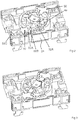
- FIG. 1 shows an embodiment of switch 10 applicable in the context of the present invention.
- the shown embodiment is a four-pole switch but the number of the poles may be different and may be any number up to ten, for instance.
- the mechanism module 28 has a cover 30. Through the cover extends the rotation shaft 32.
- a handle (not shown) may be attached to the rotation shaft to enable operation of the switch.
- the base and intermediate bodies have holes for receiving and tightening a current conductor with a connector screw 38.
- Figure 1 also shows gas exhaust holes 34A, 34B in some of the modules.
- a fastening member 36 for attaching to switch to a mounting plate, for instance.
- Figures 2 and 3 show an embodiment on equipped intermediate module, Figure 2 showing the module in the disconnected state, and Figure 3 in the contacted state.
- the module 24 there are arranged two stationary contacts 50 and 52 opposite to each other with respect to the rotation shaft, or rotation axis of the switch.
- a roll 32A which forms part of the rotation shaft of the switch.
- a movable contact 40 is arranged to the roll 32A such that rotation of the roll causes the movable contact 40 to pivot between the open position of the switch shown in Figure 2 and the closed position of the switch shown in Figure 3 .
- a contact bridge between the stationary contacts is broken, whereas in Figure 3 , the movable contact forms the contact bridge, that is, the contact blades make an electrical contact to the stationary contact received between the contact blades.
- the rotation of the rotary contact may be arranged such that when the rotary contact is rotated from the open position to the closed position, the rotation shaft and the roll are rotated clockwise, and vice versa.
- the rotation angle between the states may be 90 degrees, for instance.
- the stationary contact has a shape of letter Y.
- the base 50C of the stationary contact is used for connecting the stationary contact to an external conductor.
- the right hand branch 50B, a support portion, is set into a recess formed into the module, thus preventing pivoting of the stationary contact.
- the left hand branch, the contact portion of the stationary contact is adapted to make the contact to the contact blades of the rotary contact 40.
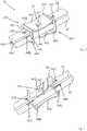
- Figure 4 highlights the positioning of the movable contact to the roll 32A. It can be seen that the roll has four vertical bars 60A, 60B, 60C and 60D. The bars are arranged at a distance from each other such that a slot is formed there between. The slot is formed by a space between bars 60A and 60B, and between bars 60C and 60D. In the case of bars 60A and 60B, the portion of the slot is formed by those portions of the bars that are closest to each other.
- the movable contact comprises three parts, a first contact blade 42, a second contact blade 44 and a traction member 46.
- the contact blades are elongate/longitudinal bars, which extend through the roll from one side to the opposite side of the roll, and via the rotation axis of the roll.
- the contact blades 42, 44 may be similar to each other. Each contact blade may be symmetric.
- the distance between the bars 60A and 60B is substantially the same as the width the contact blades 42, 44 such that the contact blades fit into the slot with a tight fitting. That is the space between the bars 60A, 60B, and bars 60C, 60D with respect to the width of the contact bar is such as to prevent pivoting of the contact blades to each other and the movable contact as a whole with respect to the roll 32A.
- the traction member is shorter than the contact blades.
- the traction member fits within the interior of the roll.
- the traction member is wider than the contact blades.
- the space for receiving the traction member may be rectangular. The space is tight such that pivoting of the traction member about the roll is prevented.
- Such a roll may be another roll similar to the shown roll 32A, or a mechanism roll of a mechanism body.
- Figure 5 shows an embodiment, where two rolls 32A, 32B have been mounted on top of each other. There two rolls form part of the rotation shaft of the switch.
- the shaft may additionally comprise one or more rolls similar to the rolls 32A, 32B, a crank, a mechanism roll and a handle.
- the rolls 32A, 32B are mounted to each other by means of teeth on the bottom of each roll that fit into respective recesses in an underlying roll.
- Each roll may include a movable contact.
- the stack of rolls may also include empty rolls having no movable contact mounted thereto.
- the movable contact 40A of the higher roll 32A is perpendicular to the movable contact 40B in the lower roll. This is advantageous in separating arcs formed in the top roll and the bottom roll as far as possible from each other, as the both movable contacts 40A, 40B are contacted from the respective stationary contacts simultaneously.
- Figure 6 shows an embodiment of a movable contact 40 in more detail.
- the movable contact of the embodiment has three separate parts, a first contact blade 42, a second contact blade 44, and a traction member 46 for pulling the contact blades against each other and/or keeping the contact blades longitudinally in alignment with each other. Furthermore, the traction member keeps the two separate contact blades together as a package. In Figure 6 , the three parts have been mounted together.
- the contact blades may be mutually similar and/or symmetrical.
- the contact blade is a longitudinal blade, which may have a cross-section of substantially letter D.
- the straight section of the D-formed cross-section sets on the outside of the contact blade, and the rounded side of the contact blade sets to the inside of the movable contact.
- the rounded sides of the contact blades are set against each other. This alleviates the receiving of the stationary contact between the contact blades.
- the stationary contact sets against the rounded contact surfaces 42A, 44A of the contact blades.
- Figure 6 shows the movable contact in a situation where a stationary contact is not placed between the contact blades. In this situation, the contact blades are kept separate from each other by using separation members.
- the separation members may be parts that have been made by punching to the contact blades from the outside of the contact blade.
- Figure 6 shows two such separation members 42B, 42C that have been punched to the first contact blade 42. The punched portion extends as a protrusion to the contact surface 42A of the contact blade.
- Figure 6 also shows how the punched protrusion extends as a separation member 44D to the contact surface 44A of the second contact blade 44.
- Each contact blade may have two such separation members, which are positioned at an equal distance from each other from the middle of the contact blade. The separation member(s) of both contact blades set against each other thus keeping the contact blades distanced from each other. When a stationary contact is placed between the contact blades, the separation members of the two contact blades may separate from each other.
- the movable contact also comprises a traction member 46.
- One purpose of the traction member is to pull/press the contact blades against each other, both in a situation when there is no stationary contact between the contact blades, and in a situation when there is stationary contact between the contact blades thus providing a contact pressure between the contact blades and the stationary contact.
- the traction force provided by the traction member may be higher than when there is no stationary contact between the contact blades.
- the traction member thus provides the needed contact pressure between the contact blades, and also to maintain the integrity of the movable contact. That is, the traction member is also arranged to keep the contact blades in place.
- the traction member shown in Figure 6 is unitary. Thus, it is made as one piece. The different portions of the unitary/integral traction member are thus not separable without breaking the structure.
- the traction member may be made of a single metal plate by first cutting the metal plate to the desired size, making the needed holes to it, and finally bending the obtained piece of plate into shown form.
- the traction member comprises two frames 460, 46P arranged at a distance from each other.
- the frames may be arranged longitudinally of the contact blades on both sides about the middle point of the contact blades.
- the distances of the frames may be equal from the middle of the contact blade.
- the frames are arranged to frame, at least partially, the pair of contact blades from all sides. That is, when the contact blades are set against each other, the frames surround the pair of contact blades from all four sides.
- the frame(s) make a full encircle around the contact blades thereby providing maximal support for the contact blades.
- the frame covers only part of the side.
- the frame may comprise short horizontal portions giving support for the second contact blade but not covering the whole width of the second contact blade.
- the frame sides other than the horizontal bar 46B may support and touch at least one of the contact blades 42, 44 all the time. Framing thus refers to in that there is at least a portion of the frame on each side of the pair of contact blades. The frame does not necessarily, however, touch the pair of contact blades from all sides.
- the frames 460, 46P are connected by a spring element 46A, which sets against the outer surface of one of the contact blades.
- the spring provides a constant contact pressure pressing the contact blades against each other.
- the traction member 46 comprises a first spring portion 46A having a first end 46B and a second end 46C.
- the spring portion 46A In the middle of the spring portion in the longitudinal direction, the spring portion 46A is in contact with the outer surface of the first contact blade 42, whereas the ends 46B, 46C are arranged at a distance from the contact blades. The middle portion between the ends is thus tensioned such that it forms a curve.
- the curved portion may be substantially uniform between the ends of the spring.
- the ends may have sloping, downwards extending strengthened portions to prevent buckling of the middle portion. Bucking can also be prevented by limiting the movement of the contact blades such that the spring never reaches its bucking dead point.
- the spring portion 46A straightens a little but the curved form is still maintained at least to some extent.
- the traction member thus comprises two frames 460, 46P arranged at a distance from each, the distance being the length of the spring connecting the frames, that is, the frames are arranged at the ends of the spring.
- the first frame 460 comprises a set of bars 46B, 46D, 46E and 46F, which are arranged perpendicular to each other. The bars may thus form a rectangular frame for limiting the movement of the contact blades placed within the interior of the frame.
- the second frame 46P is provided similarly at the other end of the spring 46A.
- the two frames are preferably similar but may also differ from each other.
- Figure 6 shows the frames as continuous frames surrounding the pair of contact blades completely, it is also possible to provide a partly discontinuous frame.
- the bar 46F may be broken from the middle, even though this may be a suboptimal solution.
- Such a frame supports the contact blade from all sides. That is, the pair of contact blades are supported by the frame from the top, bottom, left and right.
- the vertical side bars 46D and 46E are arranged at such a distance that the contact blades can be placed between them with a tight fitting. That is, horizontal movement and pivoting of the contact blades with respect to the traction member is prevented.
- the horizontal bars 46B and 46F there is predetermined clearance between the horizontal bars 46B and 46F.
- the spring portion 46A forces the second contact blade 44 against the horizontal bar 46F.
- the distance between the horizontal bars 46B and 46F is dimensioned such that when the stationary contact is placed between the contact blades 42, 44, the outer surface of the first contact blade 42 sets against the vertical bar 46B, and the outer surface of the second contact blade 44 sets against the vertical bar 46F.
- the horizontal bars 46B and 46F may be arranged at such a distance from each other that there is a clearance between the outer surface of the first contact blade and the bar 46B even though there is a stationary contact between the blades.
- the second frame may be positioned at an equal distance from the middle point 46I of the traction member.
- the second end 46C thus forms one vertical bar of the rectangular second frame.
- the traction member comprises a first locking member for locking the first contact blade longitudinally to the traction member. Furthermore, the traction member may comprise a second locking member for locking the second contact blade longitudinally to the traction member.
- the first locking member may comprise a hole 46I for receiving a stud/pin 42F formed to the first contact blade 42.
- the hole 46I may be arranged in the middle of the spring element 46A. That is, the hole may be longitudinally between the bars 46B, 46C in the middle of the spring. The hole may be in the middle of the spring also in the transverse direction to the longitudinal direction.
- the stud 42F may have been formed by punching to the first contact blade 42. The stud has been punched from the side of the contact surface of the first contact blade and thus forms a protrusion on the outer surface of the first contact blade. The stud 42F and the hole 46I prevent the longitudinal movement of the first contact blade 42 with respect to the traction member 46.
- the second locking member is provided for locking the second contact blade longitudinally to the traction member.
- the second locking member is highlighted with references 46G, 46H and 46J.
- the reference 46G refers to a locking portion, which is continuously in contact with the outer surface of the second contact blade.
- the locking portion 46G may be arranged at the same level as the lower bar 46F of the first frame and a corresponding bar of the second frame.
- the second locking member may comprise a similar stud-hole arrangement as the first locking member. That is, the second contact blade 44 may comprise a stud/pin on its outer surface, and the locking portion 46G of the locking member may comprise a hole 46J for receiving the stud of the second contact blade 44.
- the second locking member 46H is preferably connected to only one of the frames. In this way, manufacture of the traction member is possible by applying the stages of cutting into appropriate size, making the needed holes, and bending to appropriate shape.
- Figure 7 shows another view of the movable contact of Figure 6 .
- the movable contact is shown from the underside such that the second contact blade 44 is on the top and the first contact blade 42 is on the bottom.
- the figure shows the separation members 44B, 44C which have been punched from the second contact blade 44.
- the separation member 44C forms a protrusion on the inside that is on the side of the contact surface of the first contact blade and sets against the separation member 42D of the first contact blade.
- a locking member in the form of a stud 44F formed to second contact blade 44, which sets to a corresponding hole made to the second locking member 46G, 46H, 46J for locking and keeping the second contact blade 44 and the traction member 46 stationary to each other in the longitudinal direction of the elongate contact blade.
- the second locking member comprises a locking portion 46G, which may be a plane-like level which sets against the outer surface of the second contact blade 44. There may be also provided a positioning portion 46H for positioning of the locking portion. The positioning portion thus begins at the end of the locking portion and gradually distances from the positioning portion and finally connects to a bar of the frame.
- the traction member is preferably made of metal, such as spring steel, for instance.
- a movable contact having two contact blades and a traction member for providing a traction force on the contact blades.
- a spring element on a first side of the traction member for pressing the first contact blade against the second contact blade.
- two support members in the form of frames at the ends of the spring element. Each support member is provided in the form of a rectangular frame and they are provided at an equal distance from the middle of the contact blade.
- the traction member comprises a first locking member for locking of the first contact blade to the traction member, and a second locking member for locking of the second contact blade to the traction member.
- the locking members are implemented by holes in the both sides of the traction member, which holes are configured to receive studs arranged on the contact blades.
- the traction member is a unitary piece.
- the movable contact is mounted by introducing the contact blades through one of the frames and pushing the contact blades so far that the studs on the outer sides of the contact blades click into the respective holes in the traction member.
- the spring elements on both sides of the movable contact are slightly displaced from each other for receiving the studs.
- Figure 8 shows a contact blade 42 from two viewing angles, from the contact surface 42A, and from the outer side 42D.
- the contact blade is punched from the direction of the outer side 42D to form recesses 42B, 42C, which appear on the contact surface 42A as respective protrusions 42D and 42E.
- the protrusions function as separation or spacer members for keeping the contact blades separated from each other such that a stationary contact can be received between the contact blades.
- the protrusion 42F is applied for locking the contact blade to the traction member.
- Figure 9 shows the traction member 46 from two viewing angles.
- the traction member is a one-piece metallic integral part whose portions cannot be separated without breaking the integrity/unitarity of the member.
- the member is flexible to certain extent such that the spring member can slightly flex by straightening when the contact is being made, and when mounting the movable contact.
- Figure 9 shows holes 46I and 46J on the traction member 46 for receiving studs of the respective contact blades.
- Figure 9 also shows two windows 46K, 46L formed by mutually perpendicular bars at opposite ends of the traction member.
- the window/frame 46K is rectangular, and the window/frame 46L is substantially rectangular.
- the window/frame has a recess on one or both of the horizontal bars for allowing the studs 42F of both contact blades to be inserted to the traction member.
- the spring of the traction member may flex.
- the traction member is open from the side of the second locking member. That is, the end of the positioning member 46G does not connect to the frame defining the window 46K. In this way, the manufacture of the unitary traction member is facilitated.
- the spring element 46A connects to the ends 46B, 46C, which form one bars of the respective frames.
- the spring element may be a uniformly curved spring between the ends.
- the form of the spring may correspond to a sector of a circle.
- the middle of the spring sets closer to the contact blades than the ends of the spring.
- the second locking member may comprise two portions, that is the locking portion 46G and the positioning portion 46H.
- the locking portion may be arranged such that it sets substantially parallel to the contact blades. It may thus be substantially perpendicular to the plane of the frames.
- the positioning portion 46H may be arranged to an angle with respect to the locking portion 46G. When seen from the frame, the positioning portion inclines towards the other side of the traction member, that is, towards the spring element.
- Figures 10 to 13 illustrate another embodiment of the movable contact.
- Figures 10 and 11 show the movable contact from the top, and the bottom.
- Figure 12 shows the structure of the contact blades, and
- Figure 13 further illustrates the traction member.
- the main elements of the movable contact shown in Figures 10 to 13 are the same as in the embodiment shown in Figures 6 to 9 . That is, there are two contact blades arranged at a distance from each other, and a unitary traction member for providing a contact pressure between the contact blades, and keeping the contact blades longitudinally fixed with respect to the traction member.
- the main differences between the two embodiments lie in the manner how the contact blades and the traction member are kept in place in longitudinal direction of the contact blades.
- Figure 10 shows the movable contact as a perspective view substantially from the top.
- the contact blades are provided for carrying electrical current between the ends of the contact blades, that is between the stationary contacts.
- Figure 10 also shows a unitary traction member made of one piece by applying plate machine-tooling methods such as cutting, piercing and bending.
- the traction member comprises at least a spring element provided against the outer surface of the first contact blade, and two frames at the end of the first spring, which frames surround/encircle the contact blades.
- the frames surround the contact blades at two separate positions in the longitudinal direction of the contact blades. Between the frames there is no support to the contact blades on the sides of the contact blades.
- the contact blades may be supported/pressed between the frames on one or both outer surfaces of the contact blades.
- the frames As the frames surround the contact blades, the frames have bars that set against the sides of the contact blades.
- the spring that is a continuation of the frame may also be wider than the outer surface of the contact blade.
- the movable contact has a spring element, which sets against the outer surface of the first contact blade.
- the spring element shown in Figure 10 has a different form from the spring shown in Figure 6 .
- the spring of Figure 10 has two tensioning portions 66B and 66C extending from the frames, and a pressing portion 66A between the tensioning portions.
- the tensioning portions may be substantially parallel to the outer surface of the contact blade.
- the pressing portion forms a curve such as a parabola between the tensioning portions.
- the spring portion contacts the contact blade only by the pressing portion.
- the spring may be symmetric, that is the tensioning portions are similar and arranged similarly on both sides of the pressing portion.
- Figure 11 highlights the embodiment of Figure 10 from the bottom.
- the first spring element has two substantially planar tensioning portions 66B, 66C, and there is a provided a ridge 66A forming the pressing portion between the tensioning portions.
- the different portions may each make substantially one third of the horizontal length of the spring element.
- Figures 10 and 11 show that the longitudinal fixing of the contact blades and the traction member to each other is arranged by using the sides of the contact blades, and one or more vertical bars of the frames. This will be explained more in detail with reference to Figures 12 and 13 .
- Figure 12 shows a contact blade from two viewing angles.
- the contact blades have some common features with the contact blades shown in Figures 6 to 9 .
- Each contact blade has separation members, which set against the corresponding separation members of the other contact blade.
- the separation members may be provided in one of the two contact blades, or in both of them.
- the contact blade of Figure 12 has a locking member for locking and keeping the contact blade longitudinally fixed with the traction member.
- this locking member was provided by a protrusion 42F, 42G, which is formed by punching from the side of the contact surface towards the outer surface such that a stud/protrusion is formed on the outer surface.
- the mutual movement is prevented by two receptacles 62E, 62F formed to the side of the contact blade. These receptacles or grooves are arranged to set against respective side walls of the two frames of the traction member.
- the receptacle may have a form of a half circle, or a parabola. Other forms are also possible.
- Figure 13 shows another embodiment of a traction member.
- the traction member comprises a spring on one side of the traction member for setting against the first contact blade.
- the frames define windows through which the contact blades can be inserted to the interior of the frames.
- the traction member comprises a locking member for keeping the contact blade(s) longitudinally in place.
- this locking member comprises a wing formed to a side bar of the frame, which wing is arranged to set to a groove provided in the contact blade.
- the wing may thus have a curved form, which may fit into a curved groove of the contact blade.
- the curved form of the wing may be such that the convex side of the curve sets towards the interior of the frame 660.
- the wing is provided in the vertical side bar of the frame. The wing may extend from the vertical side bar towards exterior of the traction member.
- the wing may have a vertical height such that it fits into the grooves of both contact blades which are arranged against each other inside the window defined by the frames of the traction member.
- the traction member comprises one spring element, which sets against the first contact blade.
- the spring presses the first contact blade against the second contact blade.
- the second contact blade is thereby pressed against the frames, which provides thus the counter-force for the pressing force of the spring.
- the spring member that sets against the contact blade has a uniform, parabola-like form.
- the spring member has a form where the parabola-like section is only in the middle of the spring and there are two substantially planar sections on both sides of the middle portion.
- the traction member comprises a first locking member for locking the first contact blade to the traction member.
- the first locking member may comprise a hole made to the spring element.
- the traction member comprises a second locking member for locking the second contact blade to the traction member.
- the second locking member may comprise a hole made to a support member that sets against the outer surface of the second contact blade.
- a vertical side bar of a frame of the traction member functions as the locking member.
- the same locking member may be arranged to lock both contact blades to the traction member.
- the contact blade may comprise a corresponding locking member for locking to the traction member.
- the locking member comprises a stud in the contact blade for locking to the spring and/or the support element.
- the locking member provided in the contact blade comprises a recess/groove in a side wall of the contact blade.
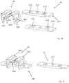
- Figures 14 to 17 show still another embodiment of a movable contact 80.
- the contact blades may be mutually similar, or there may be slight differences between them.
- the contact blades comprise contact surfaces 82A, 84A that are to be assembled so as to face each other and to receive a stationary contact between them.
- one or both of the contact blades comprises one or more separation members 84D, 84E for keeping the contact blades at a predetermined distance from each other.
- the separation members have been obtained by punching from the opposite side such that recesses 82B, 82C are formed on the outer sides of the contact blades.
- the form of the recess on the outer surface may be substantially rectangular.
- the separation members 84D, 84E may appear as cut pyramids.
- the traction member 86 of Figure 14 has two frames/windows 86K, 86L arranged at a distance from other.
- the frames are arranged to receive and envelope the pair of contact blades to the interior of the frames.
- the windows may be perpendicular to the longitudinal direction of the contact blades, and may be substantially rectangular.
- the horizontal bars, such as the bar 86F, of the windows may have a locking member 86M, 86N for co-operating with a locking member of a contact blade.
- the locking member(s) 86M, 86N may be arranged on the opposite side of the window than the spring member connecting the frames.
- the locking member of the window may be arranged as a protrusion that protrudes towards the interior of the window from the horizontal bar.
- Figure 15 illustrates the mounting of the movable contact.
- One of the contact blades 84 has been inserted to the interior of the windows such that the locking members provided on the vertical side bars of the two windows lock to the recesses on the outer sides of the contact blade 84.
- the contact blade 84 that is provided on the opposite side of the traction member than the spring member 86 is assembled first.
- the second contact blade 82 is assembled to the interior of the frames.
- the second contact blade 82 is locked to the traction member with the protrusion 82F that has been arranged to the outer surface of and to middle of the contact blade 82. That protrusion 82F is inserted to a hole that is provided in the spring member 86 that connects the two windows of the traction member.
- the hole may be similar to the hole 46I shown in Figure 9 .
- the spring may be arranged to the edges of the frames, and may comprise a middle portion 86A that sets closer to the contact blade 82 than the end portions 86B, 86C.
- the contact blades may be locked to the traction member with different locking members, although the contact blades may be mutually similar.
- Figures 16 and 17 show the movable contact in an assembled state from two different viewing angles.
- Figure 16 shows the movable contact having the spring member 86 on top, whereas in Figure 17 the spring member is on the bottom.
- Figure 16 corresponds to the assembly of Figure 15 , where the top contact blade 82 has been inserted above the bottom contact blade 84.
- the spring member 86 flexes upwards from the middle so as to allow insertion of the contact blade 82 such that the protrusion in the top contact blade can insert to the respective hole provided in the middle of the spring member 86, which is the lowest part of the spring member 86 being in contact with the contact blade 82 and thus providing the traction force between the contact blades 82, 84.
- Figure 17 shows the movable contact from the bottom. It can be seen that the locking member 86N of the traction member, which may be a tooth in the horizontal bar 86F of the window, is locked to the recess 84C of the contact blade 84 such that longitudinal movement of the contact blade with respect to the traction member is prevented. There may be provided another similar arrangement at the other frame of the traction member.
- the separation members have been arranged to the contact blades to such a position, which coincides with the position of the frames of the traction member 86.
- the separation member is thus utilized in two distinct purposes. On the first hand, it separates the contact blade from another contact blade. Secondly, the recess formed when forming the separation member is utilized in longitudinal locking of the contact blade.
- a traction member for a movable contact of an electric switch.
- the traction member comprises two frame portions for enveloping a pair of contact blades, and a spring member arranged between the frame portions for providing an attraction force between the contact blades, the traction member further comprising a locking member for locking the contact blades to the traction member for preventing longitudinal movement of the contact blades with respect to the traction member.
- the spring member may be attached to the edges of the frames, and the spring member comprises a portion that is closer to the contact blades than the edges of the frames.
- the traction member comprises also a locking member for longitudinal locking of the contact blades.
- this locking member comprises two holes 46I, 46J that receive respective protrusions of the contact blades.
- the locking member comprises wings 66Q, 66R, which set to respective recesses formed to the contact blades.
- the locking member comprises teeth that set to recesses of the first contact blade, which are formed when separation members are formed to the contact blades. The other contact blade is locked by the locking member 82F of the contact blade being inserted to a hole in the spring middle portion 86A.
- the traction member provides a plurality of the tasks. It locks the contact blades such that their longitudinal movement with respect to the traction member is prevented. Thus also the longitudinal movement of the contact blades with respect to each other is prevented.
- the traction member also provides a traction force which attracts the contact blades against each other.
- the traction also supports the contact blades from the sides, whereby twisting of the contact blades is prevented.
Landscapes
- Contacts (AREA)
- Connector Housings Or Holding Contact Members (AREA)
- Push-Button Switches (AREA)
Description
- The invention relates to electric switches, especially to a movable contact of a rotary electric switch.
- In a rotary switch, a movable rotary contact is arranged to rotate such as to connect to or disconnect from stationary contacts of the switch. To ensure optimal electric properties of the switch, the movable contact should have good electric conduction properties. For this purpose, it is also needed that the contact between the movable contact and the stationary contact(s) must be tight such that forming of an air gap between them, in connected state, is prevented.
-
EP 1213730 discloses a circuit breaking mechanism that has fixed contacts, an engagement shaft and moving contacts. The moving contacts have two parallel knife sections. Flexible contact is formed by a flexible grip on the contact arms whilst maintaining mechanical decoupling. Moving the engagement shaft closes the knife section onto the fixed contact. - Furthermore, it is desired that the movable contact is easy to assemble. In view of known structures, there is demand for an improved movable contact.
- An object of the invention is to provide an improved movable contact. This is achieved with the invention defined in the independent claim 1.
- Some advantageous embodiments are disclosed in the dependent claims.
- The invention relates to rotary switches having a rotary contact and stationary contacts. The rotary contact is arranged to rotate about a rotation axis, and the stationary contacts are arranged opposite to each other with respect to the rotation axis of the rotary contact.
- The rotary contact according to the invention has a sandwich structure having two contact blades arranged at a distance from each other for receiving a stationary contact between the contact blades.
- Preferably, the movable contact has an elongate structure. The movable contact may be arranged to contact stationary contacts at both ends of the movable contact. Making and breaking the contact occurs simultaneously at both ends of the movable contact.
- The contact blades of the movable contact are arranged at a distance from each other by a separation member. The separation member may be a protrusion in the contact blade made by punching. Both contact blades may be similar, whereby the protrusions may set against each other thus together forming the total minimum separation between the contact blades. When the stationary contact is guided between the contact blades, the contact blades may move further away from each other than provided by the separation member(s).
- There is provided a traction member for attracting the contact blades towards each other. The traction member comprises a spring member at least on one side of the pair of contact blades. The traction member may comprise at least two frames framing or circumventing the pair contact blades when the contact blades are set against each other. The frames limit the movement of the contact blades in the direction transverse to the longitudinal direction of the contact blades. The traction member is a unitary piece.
- The traction member and/or the contact blades may comprise means for preventing their longitudinal movement with respect to each other. In an embodiment, each contact blade comprises a stud or pin, and the traction member comprises a hole, which when fitted together, prevent their mutual longitudinal movement. In another embodiment, the contact blade comprises a recess or groove for receiving a wall of the frame of the traction member. The wall of the traction member may comprise a protrusion or wing to be placed into the groove of the contact blade.
- In the following, embodiments of invention will be described in more detail referring to drawings, where
-
Figure 1 shows an embodiment of a switch; -
Figure 2 shows a contact module having the contacts in open position; -
Figure 3 shows a contact module having the contacts in closed position; -
Figure 4 shows an embodiment of a force transmission roll having a movable contact placed therein; -
Figure 5 shows two force transmission rolls having movable contacts placed therein; -
Figure 6 shows an embodiment of a movable contact; -
Figure 7 shows another view of the movable contact ofFigure 6 ; -
Figure 8 shows the contact blades of the movable contact ofFigure 6 ; -
Figure 9 shows two views of the traction member of the movable contact ofFigure 6 ; -
Figure 10 shows another embodiment of a movable contact; -
Figure 11 shows another view of the movable contact ofFigure 10 ; -
Figure 12 shows the contact blades of the movable contact ofFigure 10 ; -
Figure 13 shows two views of the traction member of the movable contact ofFigure 10 ; -
Figure 14 shows still another embodiment of a movable contact; -
Figure 15 shows the movable contact partly assembled; -
Figure 16 shows a first view of the movable contact assembled; and -
Figure 17 shows a second view of the movable contact assembled. -
Figure 1 shows an embodiment ofswitch 10 applicable in the context of the present invention. The shown embodiment is a four-pole switch but the number of the poles may be different and may be any number up to ten, for instance. There is a switch module per each pole. InFigure 1 , there is abase module 20 and threeintermediate modules intermediate module 26, there is arranged a mechanism module taking care of the rotation actions of the switch. The mechanism module 28 has acover 30. Through the cover extends therotation shaft 32. A handle (not shown) may be attached to the rotation shaft to enable operation of the switch. - The base and intermediate bodies have holes for receiving and tightening a current conductor with a
connector screw 38.Figure 1 also showsgas exhaust holes 34A, 34B in some of the modules. There is also shown afastening member 36 for attaching to switch to a mounting plate, for instance. -
Figures 2 and 3 show an embodiment on equipped intermediate module,Figure 2 showing the module in the disconnected state, andFigure 3 in the contacted state. - Within the
module 24, there are arranged twostationary contacts roll 32A, which forms part of the rotation shaft of the switch. Amovable contact 40 is arranged to theroll 32A such that rotation of the roll causes themovable contact 40 to pivot between the open position of the switch shown inFigure 2 and the closed position of the switch shown inFigure 3 . In the open position of the switch, a contact bridge between the stationary contacts is broken, whereas inFigure 3 , the movable contact forms the contact bridge, that is, the contact blades make an electrical contact to the stationary contact received between the contact blades. The rotation of the rotary contact may be arranged such that when the rotary contact is rotated from the open position to the closed position, the rotation shaft and the roll are rotated clockwise, and vice versa. The rotation angle between the states may be 90 degrees, for instance. - In the shown embodiment, the stationary contact has a shape of letter Y. The base 50C of the stationary contact is used for connecting the stationary contact to an external conductor. The
right hand branch 50B, a support portion, is set into a recess formed into the module, thus preventing pivoting of the stationary contact. The left hand branch, the contact portion of the stationary contact, is adapted to make the contact to the contact blades of therotary contact 40. -
Figure 4 highlights the positioning of the movable contact to theroll 32A. It can be seen that the roll has fourvertical bars bars bars bars - The movable contact comprises three parts, a
first contact blade 42, asecond contact blade 44 and atraction member 46. The contact blades are elongate/longitudinal bars, which extend through the roll from one side to the opposite side of the roll, and via the rotation axis of the roll. Thecontact blades - The distance between the
bars contact blades bars roll 32A. - As the
Figures 4 and 5 show, the traction member is shorter than the contact blades. The traction member fits within the interior of the roll. Furthermore, the traction member is wider than the contact blades. There are insertions in thebars 60A to 60D, which form a space for receiving the traction member with a tight fitting. The space for receiving the traction member may be rectangular. The space is tight such that pivoting of the traction member about the roll is prevented. - Between the
bars bars roll 32A. Such a roll may be another roll similar to the shownroll 32A, or a mechanism roll of a mechanism body. -
Figure 5 shows an embodiment, where tworolls rolls rolls - Each roll may include a movable contact. Although the embodiment of
Figure 5 shows both rolls having a movable contact, the stack of rolls may also include empty rolls having no movable contact mounted thereto. - In the embodiment of
Figure 5 , themovable contact 40A of thehigher roll 32A is perpendicular to themovable contact 40B in the lower roll. This is advantageous in separating arcs formed in the top roll and the bottom roll as far as possible from each other, as the bothmovable contacts -
Figure 6 shows an embodiment of amovable contact 40 in more detail. The movable contact of the embodiment has three separate parts, afirst contact blade 42, asecond contact blade 44, and atraction member 46 for pulling the contact blades against each other and/or keeping the contact blades longitudinally in alignment with each other. Furthermore, the traction member keeps the two separate contact blades together as a package. InFigure 6 , the three parts have been mounted together. - The contact blades may be mutually similar and/or symmetrical. The contact blade is a longitudinal blade, which may have a cross-section of substantially letter D. The straight section of the D-formed cross-section sets on the outside of the contact blade, and the rounded side of the contact blade sets to the inside of the movable contact. The rounded sides of the contact blades are set against each other. This alleviates the receiving of the stationary contact between the contact blades. When being between the contact blades, the stationary contact sets against the rounded contact surfaces 42A, 44A of the contact blades.
-
Figure 6 shows the movable contact in a situation where a stationary contact is not placed between the contact blades. In this situation, the contact blades are kept separate from each other by using separation members. The separation members may be parts that have been made by punching to the contact blades from the outside of the contact blade.Figure 6 shows twosuch separation members 42B, 42C that have been punched to thefirst contact blade 42. The punched portion extends as a protrusion to thecontact surface 42A of the contact blade. -
Figure 6 also shows how the punched protrusion extends as aseparation member 44D to the contact surface 44A of thesecond contact blade 44. Each contact blade may have two such separation members, which are positioned at an equal distance from each other from the middle of the contact blade. The separation member(s) of both contact blades set against each other thus keeping the contact blades distanced from each other. When a stationary contact is placed between the contact blades, the separation members of the two contact blades may separate from each other. - In addition to the contact blades, the movable contact also comprises a
traction member 46. One purpose of the traction member is to pull/press the contact blades against each other, both in a situation when there is no stationary contact between the contact blades, and in a situation when there is stationary contact between the contact blades thus providing a contact pressure between the contact blades and the stationary contact. When there is a stationary contact between the contact blades, the traction force provided by the traction member may be higher than when there is no stationary contact between the contact blades. - Making the contact by guiding the stationary contact between the contact blades thus tensions the one or more springs of the traction member. The traction member thus provides the needed contact pressure between the contact blades, and also to maintain the integrity of the movable contact. That is, the traction member is also arranged to keep the contact blades in place.
- The traction member shown in
Figure 6 is unitary. Thus, it is made as one piece. The different portions of the unitary/integral traction member are thus not separable without breaking the structure. The traction member may be made of a single metal plate by first cutting the metal plate to the desired size, making the needed holes to it, and finally bending the obtained piece of plate into shown form. - The traction member comprises two
frames - The frames are arranged to frame, at least partially, the pair of contact blades from all sides. That is, when the contact blades are set against each other, the frames surround the pair of contact blades from all four sides.
- Preferably, the frame(s) make a full encircle around the contact blades thereby providing maximal support for the contact blades. In an alternative embodiment, on one side of the contact blades, the frame covers only part of the side. For instance, on the side of the second contact blade, the frame may comprise short horizontal portions giving support for the second contact blade but not covering the whole width of the second contact blade. In the frame, the frame sides other than the
horizontal bar 46B may support and touch at least one of thecontact blades - The
frames spring element 46A, which sets against the outer surface of one of the contact blades. In this way, the spring provides a constant contact pressure pressing the contact blades against each other. Various embodiments of the traction member will become apparent from the following examples. It is noted that even though the following examples make reference to directions such as horizontal, vertical, left, top, and so on, these are to be understood as only illustrating the shown embodiments and may vary depending on the usage position of the switch. - In
Figure 6 , thetraction member 46 comprises afirst spring portion 46A having afirst end 46B and a second end 46C. In the middle of the spring portion in the longitudinal direction, thespring portion 46A is in contact with the outer surface of thefirst contact blade 42, whereas the ends 46B, 46C are arranged at a distance from the contact blades. The middle portion between the ends is thus tensioned such that it forms a curve. The curved portion may be substantially uniform between the ends of the spring. The ends may have sloping, downwards extending strengthened portions to prevent buckling of the middle portion. Bucking can also be prevented by limiting the movement of the contact blades such that the spring never reaches its bucking dead point. Thus, when a stationary contact is placed between the contact blades, thespring portion 46A straightens a little but the curved form is still maintained at least to some extent. - The traction member thus comprises two
frames Figure 6 , thefirst frame 460 comprises a set ofbars second frame 46P is provided similarly at the other end of thespring 46A. The two frames are preferably similar but may also differ from each other. - Even though
Figure 6 , and other Figures show the frames as continuous frames surrounding the pair of contact blades completely, it is also possible to provide a partly discontinuous frame. For instance, inFigure 6 , thebar 46F may be broken from the middle, even though this may be a suboptimal solution. Such a frame, however, supports the contact blade from all sides. That is, the pair of contact blades are supported by the frame from the top, bottom, left and right. - In an embodiment, the vertical side bars 46D and 46E are arranged at such a distance that the contact blades can be placed between them with a tight fitting. That is, horizontal movement and pivoting of the contact blades with respect to the traction member is prevented.
- In an embodiment, there is predetermined clearance between the
horizontal bars spring portion 46A forces thesecond contact blade 44 against thehorizontal bar 46F. In that situation, there is a gap between thehorizontal bar 46B and the outer side of thecontact blade 42. However, the distance between thehorizontal bars contact blades first contact blade 42 sets against thevertical bar 46B, and the outer surface of thesecond contact blade 44 sets against thevertical bar 46F. Alternatively, thehorizontal bars bar 46B even though there is a stationary contact between the blades. - There is also provided a second frame similar to the first frame. The second frame may be positioned at an equal distance from the middle point 46I of the traction member. The second end 46C thus forms one vertical bar of the rectangular second frame.
- In an embodiment, the traction member comprises a first locking member for locking the first contact blade longitudinally to the traction member. Furthermore, the traction member may comprise a second locking member for locking the second contact blade longitudinally to the traction member.
- The first locking member may comprise a hole 46I for receiving a stud/
pin 42F formed to thefirst contact blade 42. The hole 46I may be arranged in the middle of thespring element 46A. That is, the hole may be longitudinally between thebars 46B, 46C in the middle of the spring. The hole may be in the middle of the spring also in the transverse direction to the longitudinal direction. Thestud 42F may have been formed by punching to thefirst contact blade 42. The stud has been punched from the side of the contact surface of the first contact blade and thus forms a protrusion on the outer surface of the first contact blade. Thestud 42F and the hole 46I prevent the longitudinal movement of thefirst contact blade 42 with respect to thetraction member 46. - The second locking member is provided for locking the second contact blade longitudinally to the traction member. The second locking member is highlighted with
references reference 46G refers to a locking portion, which is continuously in contact with the outer surface of the second contact blade. There is also provided apositioning portion 46H, which is arranged at a distance from the outer surface of the contact blade. The lockingportion 46G may be arranged at the same level as thelower bar 46F of the first frame and a corresponding bar of the second frame. The second locking member may comprise a similar stud-hole arrangement as the first locking member. That is, thesecond contact blade 44 may comprise a stud/pin on its outer surface, and the lockingportion 46G of the locking member may comprise ahole 46J for receiving the stud of thesecond contact blade 44. - As can be seen, the
second locking member 46H is preferably connected to only one of the frames. In this way, manufacture of the traction member is possible by applying the stages of cutting into appropriate size, making the needed holes, and bending to appropriate shape. -
Figure 7 shows another view of the movable contact ofFigure 6 . In the figure, the movable contact is shown from the underside such that thesecond contact blade 44 is on the top and thefirst contact blade 42 is on the bottom. - The figure shows the
separation members second contact blade 44. Theseparation member 44C forms a protrusion on the inside that is on the side of the contact surface of the first contact blade and sets against theseparation member 42D of the first contact blade. - It can be seen that there is arranged a locking member in the form of a
stud 44F formed tosecond contact blade 44, which sets to a corresponding hole made to thesecond locking member second contact blade 44 and thetraction member 46 stationary to each other in the longitudinal direction of the elongate contact blade. - The second locking member comprises a locking
portion 46G, which may be a plane-like level which sets against the outer surface of thesecond contact blade 44. There may be also provided apositioning portion 46H for positioning of the locking portion. The positioning portion thus begins at the end of the locking portion and gradually distances from the positioning portion and finally connects to a bar of the frame. - The traction member is preferably made of metal, such as spring steel, for instance.
- In the embodiment shown in
Figures 6 and 7 there is thus provided a movable contact having two contact blades and a traction member for providing a traction force on the contact blades. There is provided a spring element on a first side of the traction member for pressing the first contact blade against the second contact blade. In the shown embodiment, there are provided two support members in the form of frames at the ends of the spring element. Each support member is provided in the form of a rectangular frame and they are provided at an equal distance from the middle of the contact blade. - The traction member comprises a first locking member for locking of the first contact blade to the traction member, and a second locking member for locking of the second contact blade to the traction member. In the shown embodiment, the locking members are implemented by holes in the both sides of the traction member, which holes are configured to receive studs arranged on the contact blades.
- The traction member is a unitary piece. The movable contact is mounted by introducing the contact blades through one of the frames and pushing the contact blades so far that the studs on the outer sides of the contact blades click into the respective holes in the traction member. When placing the studs into the holes, the spring elements on both sides of the movable contact are slightly displaced from each other for receiving the studs.
-
Figure 8 shows acontact blade 42 from two viewing angles, from thecontact surface 42A, and from theouter side 42D. The contact blade is punched from the direction of theouter side 42D to formrecesses 42B, 42C, which appear on thecontact surface 42A asrespective protrusions further protrusion 42F, which has been punched from thecontact surface 42A such that a recess 42G is formed to the side of thecontact surface 42A. Theprotrusion 42F is applied for locking the contact blade to the traction member. -
Figure 9 shows thetraction member 46 from two viewing angles. The traction member is a one-piece metallic integral part whose portions cannot be separated without breaking the integrity/unitarity of the member. The member is flexible to certain extent such that the spring member can slightly flex by straightening when the contact is being made, and when mounting the movable contact. -
Figure 9 showsholes 46I and 46J on thetraction member 46 for receiving studs of the respective contact blades.Figure 9 also shows twowindows frame 46K is rectangular, and the window/frame 46L is substantially rectangular. When mounting the movable contact, the contact blades are pushed to the traction member from thewindow 46L. The window/frame has a recess on one or both of the horizontal bars for allowing thestuds 42F of both contact blades to be inserted to the traction member. When inserting the contact blades to the traction member, the spring of the traction member may flex. - As the figures show, the traction member is open from the side of the second locking member. That is, the end of the
positioning member 46G does not connect to the frame defining thewindow 46K. In this way, the manufacture of the unitary traction member is facilitated. - As
Figure 9 shows, thespring element 46A connects to theends 46B, 46C, which form one bars of the respective frames. The spring element may be a uniformly curved spring between the ends. The form of the spring may correspond to a sector of a circle. The middle of the spring sets closer to the contact blades than the ends of the spring. - The second locking member may comprise two portions, that is the locking
portion 46G and thepositioning portion 46H. The locking portion may be arranged such that it sets substantially parallel to the contact blades. It may thus be substantially perpendicular to the plane of the frames. Thepositioning portion 46H may be arranged to an angle with respect to the lockingportion 46G. When seen from the frame, the positioning portion inclines towards the other side of the traction member, that is, towards the spring element. -
Figures 10 to 13 illustrate another embodiment of the movable contact.Figures 10 and 11 show the movable contact from the top, and the bottom.Figure 12 shows the structure of the contact blades, andFigure 13 further illustrates the traction member. The main elements of the movable contact shown inFigures 10 to 13 are the same as in the embodiment shown inFigures 6 to 9 . That is, there are two contact blades arranged at a distance from each other, and a unitary traction member for providing a contact pressure between the contact blades, and keeping the contact blades longitudinally fixed with respect to the traction member. The main differences between the two embodiments lie in the manner how the contact blades and the traction member are kept in place in longitudinal direction of the contact blades. -
Figure 10 shows the movable contact as a perspective view substantially from the top. There are twocontact blades -
Figure 10 also shows a unitary traction member made of one piece by applying plate machine-tooling methods such as cutting, piercing and bending. The traction member comprises at least a spring element provided against the outer surface of the first contact blade, and two frames at the end of the first spring, which frames surround/encircle the contact blades. - The frames surround the contact blades at two separate positions in the longitudinal direction of the contact blades. Between the frames there is no support to the contact blades on the sides of the contact blades. The contact blades may be supported/pressed between the frames on one or both outer surfaces of the contact blades.
- As the frames surround the contact blades, the frames have bars that set against the sides of the contact blades. Thus, the spring that is a continuation of the frame, may also be wider than the outer surface of the contact blade..
- In the embodiment of
Figure 10 , the movable contact has a spring element, which sets against the outer surface of the first contact blade. The spring element shown inFigure 10 has a different form from the spring shown inFigure 6 . The spring ofFigure 10 has two tensioningportions pressing portion 66A between the tensioning portions. The tensioning portions may be substantially parallel to the outer surface of the contact blade. The pressing portion forms a curve such as a parabola between the tensioning portions. The spring portion contacts the contact blade only by the pressing portion. The spring may be symmetric, that is the tensioning portions are similar and arranged similarly on both sides of the pressing portion. -
Figure 11 highlights the embodiment ofFigure 10 from the bottom. As can be seen, the first spring element has two substantiallyplanar tensioning portions ridge 66A forming the pressing portion between the tensioning portions. By way of an example in can be mentioned that the different portions may each make substantially one third of the horizontal length of the spring element. -
Figures 10 and 11 show that the longitudinal fixing of the contact blades and the traction member to each other is arranged by using the sides of the contact blades, and one or more vertical bars of the frames. This will be explained more in detail with reference toFigures 12 and 13 . -
Figure 12 shows a contact blade from two viewing angles. The contact blades have some common features with the contact blades shown inFigures 6 to 9 . Each contact blade has separation members, which set against the corresponding separation members of the other contact blade. The separation members may be provided in one of the two contact blades, or in both of them. - The contact blade of
Figure 12 has a locking member for locking and keeping the contact blade longitudinally fixed with the traction member. InFigure 8 , this locking member was provided by aprotrusion 42F, 42G, which is formed by punching from the side of the contact surface towards the outer surface such that a stud/protrusion is formed on the outer surface. In the embodiment ofFigure 12 , the mutual movement is prevented by tworeceptacles - As
Figure 12 shows, the receptacle may have a form of a half circle, or a parabola. Other forms are also possible. -
Figure 13 shows another embodiment of a traction member. The traction member comprises a spring on one side of the traction member for setting against the first contact blade. There are two frames at both ends of the traction member, wherein the frames are connected by the spring. The frames define windows through which the contact blades can be inserted to the interior of the frames. - The traction member comprises a locking member for keeping the contact blade(s) longitudinally in place. In the shown embodiment, this locking member comprises a wing formed to a side bar of the frame, which wing is arranged to set to a groove provided in the contact blade. The wing may thus have a curved form, which may fit into a curved groove of the contact blade. The curved form of the wing may be such that the convex side of the curve sets towards the interior of the
frame 660. The wing is provided in the vertical side bar of the frame. The wing may extend from the vertical side bar towards exterior of the traction member. The wing may have a vertical height such that it fits into the grooves of both contact blades which are arranged against each other inside the window defined by the frames of the traction member. There may be provided a wing in both of the frames, or in one of the frames only. Correspondingly, there may be provided one or two grooves/recesses on each contact blade. - The
Figures 6 to 13 show two embodiments of the movable contact. There are some similarities between the embodiments, but also some differences. It is understood that various modifications may be done to the shown embodiments and various combinations may be made of the two embodiments. Some of them will be shortly discussed in the following. - In an embodiment, the traction member comprises one spring element, which sets against the first contact blade. The spring presses the first contact blade against the second contact blade. The second contact blade is thereby pressed against the frames, which provides thus the counter-force for the pressing force of the spring.
- In an embodiment, the spring member that sets against the contact blade has a uniform, parabola-like form. In another embodiment, the spring member has a form where the parabola-like section is only in the middle of the spring and there are two substantially planar sections on both sides of the middle portion.
- In an embodiment, the traction member comprises a first locking member for locking the first contact blade to the traction member. The first locking member may comprise a hole made to the spring element.
- In an embodiment, the traction member comprises a second locking member for locking the second contact blade to the traction member. The second locking member may comprise a hole made to a support member that sets against the outer surface of the second contact blade.
- In another embodiment, a vertical side bar of a frame of the traction member functions as the locking member. The same locking member may be arranged to lock both contact blades to the traction member.
- The contact blade may comprise a corresponding locking member for locking to the traction member. In an embodiment, the locking member comprises a stud in the contact blade for locking to the spring and/or the support element.
- In an embodiment, the locking member provided in the contact blade comprises a recess/groove in a side wall of the contact blade.
-
Figures 14 to 17 show still another embodiment of a movable contact 80. As in the previous Figures, there are two contact blades and a traction member for keeping the contact blades in place with respect to each other. The contact blades may be mutually similar, or there may be slight differences between them. - The contact blades comprise
contact surfaces more separation members 84D, 84E for keeping the contact blades at a predetermined distance from each other. Preferably, the separation members have been obtained by punching from the opposite side such that recesses 82B, 82C are formed on the outer sides of the contact blades. AsFigure 14 shows, the form of the recess on the outer surface may be substantially rectangular. On the contact surface, theseparation members 84D, 84E may appear as cut pyramids. - As in previous figures, also the
traction member 86 ofFigure 14 has two frames/windows bar 86F, of the windows may have a lockingmember -
Figure 15 illustrates the mounting of the movable contact. One of thecontact blades 84 has been inserted to the interior of the windows such that the locking members provided on the vertical side bars of the two windows lock to the recesses on the outer sides of thecontact blade 84. AsFigure 15 shows, thecontact blade 84 that is provided on the opposite side of the traction member than thespring member 86 is assembled first. - When the
first contact blade 84 has been assembled, thesecond contact blade 82 is assembled to the interior of the frames. Thesecond contact blade 82 is locked to the traction member with theprotrusion 82F that has been arranged to the outer surface of and to middle of thecontact blade 82. Thatprotrusion 82F is inserted to a hole that is provided in thespring member 86 that connects the two windows of the traction member. The hole may be similar to the hole 46I shown inFigure 9 . The spring may be arranged to the edges of the frames, and may comprise amiddle portion 86A that sets closer to thecontact blade 82 than theend portions 86B, 86C. - As shown in
Figure 15 , the contact blades may be locked to the traction member with different locking members, although the contact blades may be mutually similar. -
Figures 16 and 17 show the movable contact in an assembled state from two different viewing angles.Figure 16 shows the movable contact having thespring member 86 on top, whereas inFigure 17 the spring member is on the bottom. -
Figure 16 corresponds to the assembly ofFigure 15 , where thetop contact blade 82 has been inserted above thebottom contact blade 84. In the assembly of thetop contact blade 82, thespring member 86 flexes upwards from the middle so as to allow insertion of thecontact blade 82 such that the protrusion in the top contact blade can insert to the respective hole provided in the middle of thespring member 86, which is the lowest part of thespring member 86 being in contact with thecontact blade 82 and thus providing the traction force between thecontact blades -
Figure 17 shows the movable contact from the bottom. It can be seen that the lockingmember 86N of the traction member, which may be a tooth in thehorizontal bar 86F of the window, is locked to the recess 84C of thecontact blade 84 such that longitudinal movement of the contact blade with respect to the traction member is prevented. There may be provided another similar arrangement at the other frame of the traction member. - Thus, in the shown embodiment, the separation members have been arranged to the contact blades to such a position, which coincides with the position of the frames of the
traction member 86. The separation member is thus utilized in two distinct purposes. On the first hand, it separates the contact blade from another contact blade. Secondly, the recess formed when forming the separation member is utilized in longitudinal locking of the contact blade. - In the shown embodiments, there is thus provided a traction member for a movable contact of an electric switch. The traction member comprises two frame portions for enveloping a pair of contact blades, and a spring member arranged between the frame portions for providing an attraction force between the contact blades, the traction member further comprising a locking member for locking the contact blades to the traction member for preventing longitudinal movement of the contact blades with respect to the traction member. The spring member may be attached to the edges of the frames, and the spring member comprises a portion that is closer to the contact blades than the edges of the frames. The traction member comprises also a locking member for longitudinal locking of the contact blades. In
Figure 9 , this locking member comprises twoholes 46I, 46J that receive respective protrusions of the contact blades. InFigure 13 , the locking member comprises wings 66Q, 66R, which set to respective recesses formed to the contact blades. InFigure 14 , the locking member comprises teeth that set to recesses of the first contact blade, which are formed when separation members are formed to the contact blades. The other contact blade is locked by the lockingmember 82F of the contact blade being inserted to a hole in the springmiddle portion 86A. - As shown the embodiments, the traction member provides a plurality of the tasks. It locks the contact blades such that their longitudinal movement with respect to the traction member is prevented. Thus also the longitudinal movement of the contact blades with respect to each other is prevented. The traction member also provides a traction force which attracts the contact blades against each other. The traction also supports the contact blades from the sides, whereby twisting of the contact blades is prevented.
- It is clear that the details can vary within the scope of the claims. The invention is not limited to direct current switches but the invention can be used in many applications where corresponding switches are used.
Claims (13)
- A movable contact of a rotary switch, comprising a pair of contact blades (42, 44, 62, 64) for making an electrical contact to a stationary contact receivable between the contact blades (42, 44, 62, 64), wherein the movable contact comprises a traction member (46, 66) for providing a traction force to attract the contact blades (42, 44, 62, 64) towards each other, the traction member (46, 66) is a unitary piece comprising two frame portions (460, 46P, 660, 66P) for framing the pair of contact blades (42, 44, 62, 64), the traction member (46, 66) further comprising a spring portion (46A, 66A, 66B, 66C) for pressing one of the contact blades (42, 62) against the other contact blade (44, 64) or the stationary contact, wherein the spring portion is arranged to connect the two frame portions (460, 46P, 660, 66P) arranged at a distance from each other, the pair of contact blades (42, 44, 62, 64) comprises a first contact blade (42, 62) and a second contact blade (44, 64) arranged at a distance from each other to receive a stationary contact between the contact blades (42, 44, 62, 64), each of the contact blades (42, 44, 62, 64) comprising a contact surface (42A, 42B) for making an electrical contact to the stationary contact, and an outer surface opposite to the contact surface, characterized in that the spring portion (46A, 66A, 66B, 66C) is arranged at least partly against the outer surface of the first contact blade (42, 62) to press the first contact blade (42, 62) against the second contact blade (44, 64) or the stationary contact whereby the second contact blade (44, 64) is pressed against the frame, which provides a counter-force to a pressing force of the spring portion (46A, 66A, 66B, 66C).
- A movable contact of a rotary switch according to claim 1, characterized in that at least one of the frames (460, 46P, 660, 66P) has a rectangular form and is arranged to support the contact blades (42, 44, 62, 64) from at least one of the outer surfaces and side surfaces being surfaces between the outer surface and the contact surface in each contact blade (42, 44, 62, 64).
- A movable contact of a rotary switch according to any preceding claim, characterized in that the frames (460, 46P, 660, 66P) are arranged, in longitudinal direction of the contact blades (42, 44, 62, 64), at an equal distance from a middle of a longitudinal length of the contact blades (42, 44, 62, 64).
- A movable contact of a rotary switch according to any preceding claim, characterized in that the frames (46O, 46P, 66O, 66P) comprise horizontal top and bottom walls for preventing the contact blades (42, 44, 62, 64) from distancing when the stationary contact is placed between the contact blades (42, 44, 62, 64).
- A movable contact of a rotary switch according to any preceding claim, characterized in that the spring portion (46A) comprises end portions that connect to the frames (460, 46P), and the spring portion (46A) is uniformly curved between the frames (460, 46P) such that the middle of the spring portion (46A) is continuously in contact with the first contact blade (42).
- A movable contact of a rotary switch according to any preceding claim, characterized in that the spring portion (66A, 66B, 66C) comprises two substantially planar portions, and a curved portion (66A) between the two planar portions pointing towards the first contact blade (62), which curved portion (66A) forms substantially one third of the length of the spring portion (66A, 66B, 66C).
- A movable contact of a rotary switch according to any preceding claim, characterized in that the traction member (46, 66) comprises a support portion (46G, 46H), which is arranged to set, between the frames, at least partly against the outer surface of the second contact blade (44, 64).
- A movable contact of a rotary switch according to claim 7, characterized in that the support portion (46G, 46H) is connected to only one of the frames (46P).
- A movable contact of a rotary switch according to any preceding claim, characterized in that at least one of the contact blades (42, 44, 62, 64) and/or the traction member (46, 66) comprise locking means (42F, 42I, 44F, 62E, 62F, 66Q, 66R) for preventing longitudinal movement of the contact blades (42, 44, 62, 64) with respect to the traction member (46, 66).
- A movable contact of a rotary switch according to any preceding any preceding claim, characterized in that at least one of the first contact blade (42, 62) and the second contact blade (44, 64) comprises a protrusion (42F, 44F) on the outer surface of the contact blade (42, 44) for locking the contact blade (42, 44) to the traction member for preventing their mutual longitudinal movement.
- A movable contact of a rotary switch according to any preceding any preceding claim, characterized in that at the spring portion (46A) setting against the first contact blade (42, 62) and/or the support portion (46G, 46H) setting against the second contact blade (44, 64) comprises an opening (46I) for receiving a protrusion (42F, 44F) of a contact blade.
- A movable contact of a rotary switch according to any preceding claim, characterized in that the frame (660, 66R) comprises a protrusion (66Q, 66R) on its vertical side bar for setting to a protrusion of a contact blade for locking the contact blade (62) and the traction member (46, 66) longitudinally to each other.
- A movable contact of a rotary switch according to any preceding claim, characterized in that at least one of the first contact blade (42, 62) and the second contact blade (44, 64) comprises a receptacle (62E, 62F) opening to a side of the contact blade for receiving a protrusion (66Q, 66R) of the frame (660, 66R) for locking the contact blade (62) and the traction member (46, 66) longitudinally to each other.
Applications Claiming Priority (2)
| Application Number | Priority Date | Filing Date | Title |
|---|---|---|---|
| FI20126349A FI125923B (en) | 2012-12-20 | 2012-12-20 | Movable contact of an electrical switch |
| PCT/FI2013/050439 WO2014096509A1 (en) | 2012-12-20 | 2013-04-19 | Movable contact of electric switch |
Publications (3)
| Publication Number | Publication Date |
|---|---|
| EP2936525A1 EP2936525A1 (en) | 2015-10-28 |
| EP2936525A4 EP2936525A4 (en) | 2015-12-30 |
| EP2936525B1 true EP2936525B1 (en) | 2017-01-25 |
Family
ID=50977659
Family Applications (1)
| Application Number | Title | Priority Date | Filing Date |
|---|---|---|---|
| EP13865502.2A Active EP2936525B1 (en) | 2012-12-20 | 2013-04-19 | Movable contact of electric switch |
Country Status (8)
| Country | Link |
|---|---|
| US (1) | US9697958B2 (en) |
| EP (1) | EP2936525B1 (en) |
| CN (1) | CN104871274B (en) |
| CA (1) | CA2895965C (en) |
| ES (1) | ES2623540T3 (en) |
| FI (1) | FI125923B (en) |
| RU (1) | RU2585750C1 (en) |
| WO (1) | WO2014096509A1 (en) |
Cited By (1)
| Publication number | Priority date | Publication date | Assignee | Title |
|---|---|---|---|---|
| DE202017104597U1 (en) | 2017-08-01 | 2018-11-13 | Walter Kraus Gmbh | Residual load-break switch |
Families Citing this family (12)
| Publication number | Priority date | Publication date | Assignee | Title |
|---|---|---|---|---|
| USD784268S1 (en) | 2014-10-16 | 2017-04-18 | Abb Oy | Switch |
| EP3364437B1 (en) * | 2017-02-17 | 2023-07-26 | Ewac Holding B.V. | Rotary switch |
| CN106783335B (en) * | 2017-02-20 | 2019-11-26 | 上海舒森电子科技有限公司 | Rotary switch |
| EP3457422B1 (en) * | 2017-09-15 | 2021-04-14 | ABB Schweiz AG | An electrical switch |
| EP3457421B1 (en) | 2017-09-15 | 2021-04-07 | ABB Schweiz AG | An electrical switch |
| FI11880U1 (en) * | 2017-09-15 | 2017-12-05 | Abb Oy | Electric switch drive unit |
| CN111276376B (en) * | 2018-12-04 | 2024-08-13 | 上海良信电器股份有限公司 | A circuit breaker moving contact structure |
| EP3726553B1 (en) * | 2019-04-18 | 2022-10-19 | ABB Schweiz AG | Switching device |
| RU199663U1 (en) * | 2020-03-25 | 2020-09-14 | Федеральное государственное унитарное предприятие «Всероссийский научно-исследовательский институт автоматики им.Н.Л.Духова» (ФГУП «ВНИИА») | Contact device |
| FR3114696B1 (en) * | 2020-09-25 | 2022-10-14 | Schneider Electric Ind Sas | Stackable block for low height control unit |
| USD1065102S1 (en) * | 2021-02-24 | 2025-03-04 | Abb Schweiz Ag | Switch-disconnector |
| EP4539071A1 (en) * | 2023-10-09 | 2025-04-16 | TE Connectivity Austria GmbH | Contact bridge and method for manufacturing a contact bridge |
Family Cites Families (13)
| Publication number | Priority date | Publication date | Assignee | Title |
|---|---|---|---|---|
| US313778A (en) * | 1885-03-10 | Chaeles m | ||
| US3137778A (en) * | 1962-04-16 | 1964-06-16 | Gen Electric | Pivotally mounted disconnect switch contacts |
| US3780239A (en) * | 1972-10-27 | 1973-12-18 | Westinghouse Electric Corp | Electrical contact assembly |
| SU570123A1 (en) * | 1976-04-20 | 1977-08-25 | Предприятие П/Я А-7359 | Contact system of electromagnetic relay and method of assemblying same |
| US4778959A (en) | 1987-04-27 | 1988-10-18 | General Electric Company | Fused disconnect switch |
| FR2618591B3 (en) * | 1987-07-24 | 1990-03-02 | Vidalenc Francois | TIGHTENING DEVICE FOR QUADRUPLE ELECTRIC CONTACT |
| SU1536450A1 (en) * | 1987-08-18 | 1990-01-15 | Специальное Проектно-Конструкторское И Технологическое Бюро По Комплектным Низковольтным Устройствам Защиты И Системной Автоматики Для Энергетики | Switching device |
| US6222139B1 (en) * | 1999-09-15 | 2001-04-24 | General Electric Company | Rotary electric switch and contact therefore |
| FR2818004B1 (en) * | 2000-12-07 | 2003-10-24 | Pommier | IMPROVEMENTS ON ELECTRICAL SWITCHING DEVICES |
| ES2180421B1 (en) * | 2001-03-30 | 2004-04-01 | Grupo Ormazabal, S.A. | BLOCK OF CONTACT BLADES FOR CUTTING LOAD SWITCHES. |
| CN102804295A (en) * | 2010-01-08 | 2012-11-28 | 库柏电子科技(上海)有限公司 | Moving contact for oil-immersed load switch |
| FI123561B (en) | 2011-06-07 | 2013-07-15 | Abb Oy | Switch |
| RU115121U1 (en) * | 2011-09-29 | 2012-04-20 | Открытое акционерное общество Саратовский электромеханический завод "Электродеталь" | ELECTRIC SWITCH |
-
2012
- 2012-12-20 FI FI20126349A patent/FI125923B/en active IP Right Grant
-
2013
- 2013-04-19 WO PCT/FI2013/050439 patent/WO2014096509A1/en not_active Ceased
- 2013-04-19 CA CA2895965A patent/CA2895965C/en active Active
- 2013-04-19 ES ES13865502.2T patent/ES2623540T3/en active Active
- 2013-04-19 RU RU2015129617/07A patent/RU2585750C1/en active
- 2013-04-19 CN CN201380067686.XA patent/CN104871274B/en active Active
- 2013-04-19 EP EP13865502.2A patent/EP2936525B1/en active Active
-
2015
- 2015-06-19 US US14/744,896 patent/US9697958B2/en active Active
Non-Patent Citations (1)
| Title |
|---|
| None * |
Cited By (5)
| Publication number | Priority date | Publication date | Assignee | Title |
|---|---|---|---|---|
| DE202017104597U1 (en) | 2017-08-01 | 2018-11-13 | Walter Kraus Gmbh | Residual load-break switch |
| WO2019025493A1 (en) | 2017-08-01 | 2019-02-07 | Walter Kraus Gmbh | REST LOAD DISCONNECT SWITCH |
| US11139123B2 (en) | 2017-08-01 | 2021-10-05 | Walter Kraus Gmbh | Residual load circuit breaker |
| EP4209385A1 (en) | 2017-08-01 | 2023-07-12 | Walter Kraus GmbH | Rotary switch body and residual load disconnecting switch |
| EP4212386A1 (en) | 2017-08-01 | 2023-07-19 | Walter Kraus GmbH | Operating method for a residual load disconnecting switch |
Also Published As
| Publication number | Publication date |
|---|---|
| EP2936525A1 (en) | 2015-10-28 |
| US9697958B2 (en) | 2017-07-04 |
| EP2936525A4 (en) | 2015-12-30 |
| CN104871274A (en) | 2015-08-26 |
| CA2895965C (en) | 2017-10-17 |
| CN104871274B (en) | 2017-09-12 |
| CA2895965A1 (en) | 2014-06-26 |
| US20150287551A1 (en) | 2015-10-08 |
| WO2014096509A1 (en) | 2014-06-26 |
| FI125923B (en) | 2016-04-15 |
| RU2585750C1 (en) | 2016-06-10 |
| FI20126349L (en) | 2014-06-21 |
| ES2623540T3 (en) | 2017-07-11 |
Similar Documents
| Publication | Publication Date | Title |
|---|---|---|
| EP2936525B1 (en) | Movable contact of electric switch | |
| US10367272B2 (en) | Spring-loaded clamping connection | |
| US8771004B2 (en) | Miniature spring clamp | |
| EP1923959A1 (en) | Electrical connector for flat conductor | |
| US7300304B1 (en) | Flat circuit board electrical connector | |
| JP5682997B2 (en) | Electrical connector | |
| CN104885303A (en) | Spring force terminal connection and electric device therewith | |
| EP1976068A2 (en) | Cable connector | |
| US11011859B1 (en) | Plug-type connector with insulation displacement contact | |
| CN100459297C (en) | Connector with a locking member | |
| WO2013109747A1 (en) | Connector | |
| CN112154573A (en) | spring terminal | |
| CN101656364A (en) | Cable connector | |
| EP4089847A2 (en) | High voltage (hv) terminal frame | |
| CN113451794B (en) | Jointing clamp | |
| CN112154574A (en) | Spring connecting terminal | |
| EP1530265B1 (en) | A connector housing assembly and an electric connector assembly | |
| KR101286493B1 (en) | Connector | |
| US6471536B1 (en) | Zero Insertion Force socket having mechanical fastening device | |
| EP3667826B1 (en) | Cable connection terminal | |
| EP1441418B1 (en) | Ribbon cable connector | |
| CN1206773C (en) | Conductor connecting element | |
| US5192223A (en) | Wire connector for cable wire, in particular of telecommunication cables | |
| CN218631826U (en) | Contact shell assembly and contactor | |
| JP2002075515A (en) | Terminal metal and joint connector |
Legal Events
| Date | Code | Title | Description |
|---|---|---|---|
| PUAI | Public reference made under article 153(3) epc to a published international application that has entered the european phase |
Free format text: ORIGINAL CODE: 0009012 |
|
| 17P | Request for examination filed |
Effective date: 20150605 |
|
| AK | Designated contracting states |
Kind code of ref document: A1 Designated state(s): AL AT BE BG CH CY CZ DE DK EE ES FI FR GB GR HR HU IE IS IT LI LT LU LV MC MK MT NL NO PL PT RO RS SE SI SK SM TR |
|
| AX | Request for extension of the european patent |
Extension state: BA ME |
|
| A4 | Supplementary search report drawn up and despatched |
Effective date: 20151130 |
|
| RIC1 | Information provided on ipc code assigned before grant |
Ipc: H01H 1/42 20060101ALI20151124BHEP Ipc: H01H 1/06 20060101AFI20151124BHEP Ipc: H01H 1/36 20060101ALI20151124BHEP Ipc: H01H 19/10 20060101ALI20151124BHEP |
|
| 17Q | First examination report despatched |
Effective date: 20160222 |
|
| DAX | Request for extension of the european patent (deleted) | ||
| REG | Reference to a national code |
Ref country code: DE Ref legal event code: R079 Ref document number: 602013016883 Country of ref document: DE Free format text: PREVIOUS MAIN CLASS: H01H0001060000 Ipc: H01H0001200000 |
|
| GRAP | Despatch of communication of intention to grant a patent |
Free format text: ORIGINAL CODE: EPIDOSNIGR1 |
|
| RIC1 | Information provided on ipc code assigned before grant |
Ipc: H01H 1/42 20060101ALI20160921BHEP Ipc: H01H 1/36 20060101ALI20160921BHEP Ipc: H01H 1/20 20060101AFI20160921BHEP |
|
| INTG | Intention to grant announced |
Effective date: 20161012 |
|
| GRAS | Grant fee paid |
Free format text: ORIGINAL CODE: EPIDOSNIGR3 |
|
| GRAA | (expected) grant |
Free format text: ORIGINAL CODE: 0009210 |
|
| AK | Designated contracting states |
Kind code of ref document: B1 Designated state(s): AL AT BE BG CH CY CZ DE DK EE ES FI FR GB GR HR HU IE IS IT LI LT LU LV MC MK MT NL NO PL PT RO RS SE SI SK SM TR |
|
| REG | Reference to a national code |
Ref country code: GB Ref legal event code: FG4D |
|
| REG | Reference to a national code |
Ref country code: CH Ref legal event code: EP |
|
| REG | Reference to a national code |
Ref country code: AT Ref legal event code: REF Ref document number: 864552 Country of ref document: AT Kind code of ref document: T Effective date: 20170215 |
|
| REG | Reference to a national code |
Ref country code: IE Ref legal event code: FG4D |
|
| REG | Reference to a national code |
Ref country code: DE Ref legal event code: R096 Ref document number: 602013016883 Country of ref document: DE |
|
| REG | Reference to a national code |
Ref country code: FR Ref legal event code: PLFP Year of fee payment: 5 |
|
| REG | Reference to a national code |
Ref country code: LT Ref legal event code: MG4D |
|
| REG | Reference to a national code |
Ref country code: NL Ref legal event code: MP Effective date: 20170125 |
|
| REG | Reference to a national code |
Ref country code: AT Ref legal event code: MK05 Ref document number: 864552 Country of ref document: AT Kind code of ref document: T Effective date: 20170125 |
|
| PG25 | Lapsed in a contracting state [announced via postgrant information from national office to epo] |
Ref country code: NL Free format text: LAPSE BECAUSE OF FAILURE TO SUBMIT A TRANSLATION OF THE DESCRIPTION OR TO PAY THE FEE WITHIN THE PRESCRIBED TIME-LIMIT Effective date: 20170125 |
|
| REG | Reference to a national code |
Ref country code: ES Ref legal event code: FG2A Ref document number: 2623540 Country of ref document: ES Kind code of ref document: T3 Effective date: 20170711 |
|
| PG25 | Lapsed in a contracting state [announced via postgrant information from national office to epo] |
Ref country code: LT Free format text: LAPSE BECAUSE OF FAILURE TO SUBMIT A TRANSLATION OF THE DESCRIPTION OR TO PAY THE FEE WITHIN THE PRESCRIBED TIME-LIMIT Effective date: 20170125 Ref country code: GR Free format text: LAPSE BECAUSE OF FAILURE TO SUBMIT A TRANSLATION OF THE DESCRIPTION OR TO PAY THE FEE WITHIN THE PRESCRIBED TIME-LIMIT Effective date: 20170426 Ref country code: IS Free format text: LAPSE BECAUSE OF FAILURE TO SUBMIT A TRANSLATION OF THE DESCRIPTION OR TO PAY THE FEE WITHIN THE PRESCRIBED TIME-LIMIT Effective date: 20170525 Ref country code: NO Free format text: LAPSE BECAUSE OF FAILURE TO SUBMIT A TRANSLATION OF THE DESCRIPTION OR TO PAY THE FEE WITHIN THE PRESCRIBED TIME-LIMIT Effective date: 20170425 Ref country code: FI Free format text: LAPSE BECAUSE OF FAILURE TO SUBMIT A TRANSLATION OF THE DESCRIPTION OR TO PAY THE FEE WITHIN THE PRESCRIBED TIME-LIMIT Effective date: 20170125 Ref country code: HR Free format text: LAPSE BECAUSE OF FAILURE TO SUBMIT A TRANSLATION OF THE DESCRIPTION OR TO PAY THE FEE WITHIN THE PRESCRIBED TIME-LIMIT Effective date: 20170125 |
|
| PG25 | Lapsed in a contracting state [announced via postgrant information from national office to epo] |
Ref country code: RS Free format text: LAPSE BECAUSE OF FAILURE TO SUBMIT A TRANSLATION OF THE DESCRIPTION OR TO PAY THE FEE WITHIN THE PRESCRIBED TIME-LIMIT Effective date: 20170125 Ref country code: AT Free format text: LAPSE BECAUSE OF FAILURE TO SUBMIT A TRANSLATION OF THE DESCRIPTION OR TO PAY THE FEE WITHIN THE PRESCRIBED TIME-LIMIT Effective date: 20170125 Ref country code: PT Free format text: LAPSE BECAUSE OF FAILURE TO SUBMIT A TRANSLATION OF THE DESCRIPTION OR TO PAY THE FEE WITHIN THE PRESCRIBED TIME-LIMIT Effective date: 20170525 Ref country code: LV Free format text: LAPSE BECAUSE OF FAILURE TO SUBMIT A TRANSLATION OF THE DESCRIPTION OR TO PAY THE FEE WITHIN THE PRESCRIBED TIME-LIMIT Effective date: 20170125 Ref country code: PL Free format text: LAPSE BECAUSE OF FAILURE TO SUBMIT A TRANSLATION OF THE DESCRIPTION OR TO PAY THE FEE WITHIN THE PRESCRIBED TIME-LIMIT Effective date: 20170125 Ref country code: SE Free format text: LAPSE BECAUSE OF FAILURE TO SUBMIT A TRANSLATION OF THE DESCRIPTION OR TO PAY THE FEE WITHIN THE PRESCRIBED TIME-LIMIT Effective date: 20170125 Ref country code: BG Free format text: LAPSE BECAUSE OF FAILURE TO SUBMIT A TRANSLATION OF THE DESCRIPTION OR TO PAY THE FEE WITHIN THE PRESCRIBED TIME-LIMIT Effective date: 20170425 |
|
| REG | Reference to a national code |
Ref country code: DE Ref legal event code: R097 Ref document number: 602013016883 Country of ref document: DE |
|
| PG25 | Lapsed in a contracting state [announced via postgrant information from national office to epo] |
Ref country code: CZ Free format text: LAPSE BECAUSE OF FAILURE TO SUBMIT A TRANSLATION OF THE DESCRIPTION OR TO PAY THE FEE WITHIN THE PRESCRIBED TIME-LIMIT Effective date: 20170125 Ref country code: SK Free format text: LAPSE BECAUSE OF FAILURE TO SUBMIT A TRANSLATION OF THE DESCRIPTION OR TO PAY THE FEE WITHIN THE PRESCRIBED TIME-LIMIT Effective date: 20170125 Ref country code: EE Free format text: LAPSE BECAUSE OF FAILURE TO SUBMIT A TRANSLATION OF THE DESCRIPTION OR TO PAY THE FEE WITHIN THE PRESCRIBED TIME-LIMIT Effective date: 20170125 Ref country code: RO Free format text: LAPSE BECAUSE OF FAILURE TO SUBMIT A TRANSLATION OF THE DESCRIPTION OR TO PAY THE FEE WITHIN THE PRESCRIBED TIME-LIMIT Effective date: 20170125 |
|
| PG25 | Lapsed in a contracting state [announced via postgrant information from national office to epo] |
Ref country code: DK Free format text: LAPSE BECAUSE OF FAILURE TO SUBMIT A TRANSLATION OF THE DESCRIPTION OR TO PAY THE FEE WITHIN THE PRESCRIBED TIME-LIMIT Effective date: 20170125 Ref country code: SM Free format text: LAPSE BECAUSE OF FAILURE TO SUBMIT A TRANSLATION OF THE DESCRIPTION OR TO PAY THE FEE WITHIN THE PRESCRIBED TIME-LIMIT Effective date: 20170125 |
|
| PLBE | No opposition filed within time limit |
Free format text: ORIGINAL CODE: 0009261 |
|
| STAA | Information on the status of an ep patent application or granted ep patent |
Free format text: STATUS: NO OPPOSITION FILED WITHIN TIME LIMIT |
|
| 26N | No opposition filed |
Effective date: 20171026 |
|
| REG | Reference to a national code |
Ref country code: IE Ref legal event code: MM4A |
|
| PG25 | Lapsed in a contracting state [announced via postgrant information from national office to epo] |
Ref country code: MC Free format text: LAPSE BECAUSE OF FAILURE TO SUBMIT A TRANSLATION OF THE DESCRIPTION OR TO PAY THE FEE WITHIN THE PRESCRIBED TIME-LIMIT Effective date: 20170125 |
|
| PG25 | Lapsed in a contracting state [announced via postgrant information from national office to epo] |
Ref country code: SI Free format text: LAPSE BECAUSE OF FAILURE TO SUBMIT A TRANSLATION OF THE DESCRIPTION OR TO PAY THE FEE WITHIN THE PRESCRIBED TIME-LIMIT Effective date: 20170125 Ref country code: LU Free format text: LAPSE BECAUSE OF NON-PAYMENT OF DUE FEES Effective date: 20170419 |
|
| REG | Reference to a national code |
Ref country code: BE Ref legal event code: MM Effective date: 20170430 |
|
| REG | Reference to a national code |
Ref country code: FR Ref legal event code: PLFP Year of fee payment: 6 |
|
| PG25 | Lapsed in a contracting state [announced via postgrant information from national office to epo] |
Ref country code: IE Free format text: LAPSE BECAUSE OF NON-PAYMENT OF DUE FEES Effective date: 20170419 |
|
| PG25 | Lapsed in a contracting state [announced via postgrant information from national office to epo] |
Ref country code: BE Free format text: LAPSE BECAUSE OF NON-PAYMENT OF DUE FEES Effective date: 20170430 |
|
| PG25 | Lapsed in a contracting state [announced via postgrant information from national office to epo] |
Ref country code: MT Free format text: LAPSE BECAUSE OF NON-PAYMENT OF DUE FEES Effective date: 20170419 |
|
| REG | Reference to a national code |
Ref country code: ES Ref legal event code: PC2A Owner name: ABB SCHWEIZ AG Effective date: 20190423 |
|
| REG | Reference to a national code |
Ref country code: CH Ref legal event code: PUE Owner name: ABB SCHWEIZ AG, CH Free format text: FORMER OWNER: ABB OY, FI |
|
| REG | Reference to a national code |
Ref country code: GB Ref legal event code: 732E Free format text: REGISTERED BETWEEN 20190516 AND 20190522 |
|
| PG25 | Lapsed in a contracting state [announced via postgrant information from national office to epo] |
Ref country code: HU Free format text: LAPSE BECAUSE OF FAILURE TO SUBMIT A TRANSLATION OF THE DESCRIPTION OR TO PAY THE FEE WITHIN THE PRESCRIBED TIME-LIMIT; INVALID AB INITIO Effective date: 20130419 |
|
| PG25 | Lapsed in a contracting state [announced via postgrant information from national office to epo] |
Ref country code: CY Free format text: LAPSE BECAUSE OF FAILURE TO SUBMIT A TRANSLATION OF THE DESCRIPTION OR TO PAY THE FEE WITHIN THE PRESCRIBED TIME-LIMIT Effective date: 20170125 |
|
| PG25 | Lapsed in a contracting state [announced via postgrant information from national office to epo] |
Ref country code: MK Free format text: LAPSE BECAUSE OF FAILURE TO SUBMIT A TRANSLATION OF THE DESCRIPTION OR TO PAY THE FEE WITHIN THE PRESCRIBED TIME-LIMIT Effective date: 20170125 |
|
| REG | Reference to a national code |
Ref country code: DE Ref legal event code: R081 Ref document number: 602013016883 Country of ref document: DE Owner name: ABB SCHWEIZ AG, CH Free format text: FORMER OWNER: ABB OY, HELSINKI, FI |
|
| PG25 | Lapsed in a contracting state [announced via postgrant information from national office to epo] |
Ref country code: TR Free format text: LAPSE BECAUSE OF FAILURE TO SUBMIT A TRANSLATION OF THE DESCRIPTION OR TO PAY THE FEE WITHIN THE PRESCRIBED TIME-LIMIT Effective date: 20170125 |
|
| PG25 | Lapsed in a contracting state [announced via postgrant information from national office to epo] |
Ref country code: AL Free format text: LAPSE BECAUSE OF FAILURE TO SUBMIT A TRANSLATION OF THE DESCRIPTION OR TO PAY THE FEE WITHIN THE PRESCRIBED TIME-LIMIT Effective date: 20170125 |
|
| PGFP | Annual fee paid to national office [announced via postgrant information from national office to epo] |
Ref country code: DE Payment date: 20250422 Year of fee payment: 13 |
|
| PGFP | Annual fee paid to national office [announced via postgrant information from national office to epo] |
Ref country code: GB Payment date: 20250423 Year of fee payment: 13 Ref country code: ES Payment date: 20250529 Year of fee payment: 13 |
|
| PGFP | Annual fee paid to national office [announced via postgrant information from national office to epo] |
Ref country code: IT Payment date: 20250424 Year of fee payment: 13 |
|
| PGFP | Annual fee paid to national office [announced via postgrant information from national office to epo] |
Ref country code: FR Payment date: 20250425 Year of fee payment: 13 |
|
| PGFP | Annual fee paid to national office [announced via postgrant information from national office to epo] |
Ref country code: CH Payment date: 20250501 Year of fee payment: 13 |