EP1213730A1 - Perfectionnements aux dispositifs de coupure élecrique - Google Patents
Perfectionnements aux dispositifs de coupure élecrique Download PDFInfo
- Publication number
- EP1213730A1 EP1213730A1 EP01403122A EP01403122A EP1213730A1 EP 1213730 A1 EP1213730 A1 EP 1213730A1 EP 01403122 A EP01403122 A EP 01403122A EP 01403122 A EP01403122 A EP 01403122A EP 1213730 A1 EP1213730 A1 EP 1213730A1
- Authority
- EP
- European Patent Office
- Prior art keywords
- knives
- shaft
- contacts
- movable contacts
- drive shaft
- Prior art date
- Legal status (The legal status is an assumption and is not a legal conclusion. Google has not performed a legal analysis and makes no representation as to the accuracy of the status listed.)
- Granted
Links
- 229910000906 Bronze Inorganic materials 0.000 claims 1
- 230000000712 assembly Effects 0.000 claims 1
- 238000000429 assembly Methods 0.000 claims 1
- 229910052790 beryllium Inorganic materials 0.000 claims 1
- ATBAMAFKBVZNFJ-UHFFFAOYSA-N beryllium atom Chemical compound [Be] ATBAMAFKBVZNFJ-UHFFFAOYSA-N 0.000 claims 1
- 239000010974 bronze Substances 0.000 claims 1
- KUNSUQLRTQLHQQ-UHFFFAOYSA-N copper tin Chemical compound [Cu].[Sn] KUNSUQLRTQLHQQ-UHFFFAOYSA-N 0.000 claims 1
- 230000000694 effects Effects 0.000 claims 1
- 239000000463 material Substances 0.000 claims 1
- 238000000926 separation method Methods 0.000 claims 1
Images


Classifications
-
- H—ELECTRICITY
- H01—ELECTRIC ELEMENTS
- H01H—ELECTRIC SWITCHES; RELAYS; SELECTORS; EMERGENCY PROTECTIVE DEVICES
- H01H1/00—Contacts
- H01H1/12—Contacts characterised by the manner in which co-operating contacts engage
- H01H1/36—Contacts characterised by the manner in which co-operating contacts engage by sliding
- H01H1/42—Knife-and-clip contacts
-
- H—ELECTRICITY
- H01—ELECTRIC ELEMENTS
- H01H—ELECTRIC SWITCHES; RELAYS; SELECTORS; EMERGENCY PROTECTIVE DEVICES
- H01H1/00—Contacts
- H01H1/12—Contacts characterised by the manner in which co-operating contacts engage
- H01H1/36—Contacts characterised by the manner in which co-operating contacts engage by sliding
- H01H1/365—Bridging contacts
Definitions
- the present invention relates to the field of devices for Blackout.
- the present invention applies in particular, although not exclusively, to electrical cut-off devices comprising rotating mobile contacts.
- Known devices of the illustrated type in particular schematically in Figure 1 attached, in a partial sectional view longitudinal axial, comprising a housing 10 which accommodates several sets of fixed contacts 20, a rotary drive shaft 30 and several sets of movable contacts 40 linked to the drive shaft 30, so that during rotational movement of the shaft 30, alternately the movable contacts 40 connect the fixed contacts 20 to each other or are separated from them.
- the movable contacts 40 are generally formed by a clamp consisting of two parallel knives 42, 44, urged in approach by blades spring 46, 48, the middle part of which bears on the drive shaft 30, while its ends rest on the knives 42, 44 nearby of their ends.
- the present invention now aims to improve the existing known devices.
- This box can be the subject of any appropriate implementation as to its constituent geometry and material.
- the breaking device comprises a shaft 300 rotatably mounted about its longitudinal axis 302.
- the shaft 300 is advantageously made of material electrically insulating thermoplastic.
- the tree 300 can in itself be the subject of numerous variant embodiments. Its structure will therefore not be described in detail thereafter.
- the shaft 300 can be rotated about the axis 302, manually or by any appropriate automation. Ways drive shaft 300, known in themselves, will not be described thereafter.
- the shaft 300 carries at least one set of movable contacts 400 intended to cooperate with at least two fixed contacts supported by the surface internal of the case.
- the fixed contacts can be known in themselves, by example of the type illustrated in FIG. 1 under the reference 20. They will therefore not described in detail below.
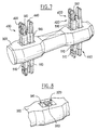
- the shaft 300 preferably carries at least three sets of movable contacts 400 distributed axially along its length (thus schematically illustrated two such sets of mobile contacts 400 on the figure 7).
- the shaft 300 carries four sets of contacts 400 mobile, especially in the case of two-phase systems.
- Each set of movable contacts 400 has two knives 420 and 440 parallels biased by elastic means 500.
- the two knives 420, 440 are of identical structure and symmetrically arranged one opposite the other.
- each knife 420 and 440 is perforated longitudinally at each end.
- each knife 420, 440 is provided with two longitudinal notches 421, 422, 441, 442 which open onto their longitudinal ends.
- each knife 420, 440 is made up of two blades parallel 423, 424, 443, 444 interconnected in the middle part by a bridge 425, 445.
- the knives 420, 440 are made of a material electrically conductive. It is preferably a relatively metal rigid, such as silver copper.
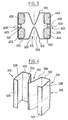
- the knives 420 and 440 are arranged in a generally radial orientation with respect to to the axis 302 of the shaft 300. More precisely still, the knives 420, 440 are arranged in cavities 310, 320 formed in the shaft 300. Thus, the knives 420, 440 cross the shaft 300 and emerge on either side of this one to cooperate with the fixed contacts 20. More precisely still, as seen in Figure 8, the two knives 420, 440 are arranged respectively in a cavity 310, 320 passing through the shaft 300 in a radial direction.
- the two cavities 310, 320 are thus separated by an element intermediate or radial membrane 330 which serves to support the knife 420, 440 in the open position of the cut-off device.
- the membrane 330 can even be openwork.
- the axial dimension of the cavities 310, 320 that is to say the dimension of these cavities considered parallel to axis 302 must be greater than the thickness of the knives 420, 440 to allow a movement of these in the cavities 310, 320 when the device cut is moved from the closed position to the open position Or vice versa.
- the elastic means 500 consist of two springs 510, in the general shape of W, arranged respectively on each end of the knives 420, 440.
- each pair of knives 420, 440 is associated with four W-shaped 510 springs
- each spring 510 has a middle portion 512 in V shape extended on both sides by two ends respectively 514, 516 in general form of C.
- the springs 510 thus have a constant section over their entire length.
- the V-shaped middle part 512 gives each spring 510 an elastic effect.
- the ends in C 514, 516 have the function of surrounding at at least partially a respective blade 423, 424, 443, 444 of a knife 420, 440 as seen in Figure 3.
- the springs 510 prohibit a free spacing of the knives 420, 440.
- each spring 510 is arranged at least partially in a recess or recess 402 formed in each blade 423, 424, 443, 444 (such step 402 is visible for example in FIG. 6). So, the engagement of the springs 510 in the recess 402 prohibits a relative longitudinal offset between spring 510 and knife 420 or 440 associated.
- each spring 510 comprises two coplanar plan sections 520, 522 interconnected by two members 524, 526 forming the aforementioned elastic V 512. This defines a concavity facing outward from W.
- the two basic sections 520, 522 are also extended respectively by two sections 528, 530 parallel to each other and respectively perpendicular to the base sections 520, 522. These sections 528, 530 delimit the ends of the spring at W. Finally, these two 528, 530 end sections are themselves extended by returns 529, 531 parallel to the base section 520, 522 and perpendicular to the sections 528, 530. The returns 529, 531 are directed towards each other, ie inward of W.
- the width of the sections 528, 530 is greater than the width of each blade 421, 423, 441, 443, as seen in FIG. 3.
- the V 512 is placed between the two knives 420, 440, the base walls 520, 522 being oriented parallel to the axis 302 in look at the intermediate wall 330 of the shaft.
- the basic sections 520, 522 are thus arranged on the outside knives 420, 440, returns 529, 531 entering the notches longitudinal 421, 422, 441, 442.
- end sections 528, 530 are positioned in the recesses 402, which are formed, as seen in the figures attached, on the outer surfaces of the knives 420, 440.
- the knives 420, 440, as well as the springs 510 are in principle mechanically separated, that is to say mechanically decoupled from the shaft 300, thanks to the clearance between the knives 420, 440 and the cavities 310, 320 and the axial thickness of the membrane 330 less than the thickness of the fixed contacts 20.
- any vibration transmission is suppressed mechanical between the sets of movable contacts 400 and the shaft 300 and thereby even from one set of movable contacts 400 to another via the shaft 300.
- FIG. 7 There is shown diagrammatically in FIG. 7 a shaft 300 equipped with two movable contact sets 400.
- each shaft 300 is fitted with minus three sets of movable contacts 400 for respectively cutting a phases of a three-phase system.
- the shaft 300 can be equipped with a fourth set of movable contacts 400 to cut the earth line as indicated previously.
- the springs 510 can be made of any elastic material suitable, preferably made of metal, for example based on beryllium bronze.
- the present invention can in particular find application in cut-off devices in which the shaft drive 300 is not mounted for rotation, but for translation.
- each set of movable contacts 400 cooperates with two fixed contacts 20.
- the invention can also find application in switching devices in which each set of movable contacts 400 cooperates with a single fixed contact 20.
- the present invention can find application in all types switch, disconnector, especially for high cut and / or low voltage, in particular for underground cut-off device.
- the present invention is not limited to this field and also covers the overhead shutdown devices.
- the present invention makes it possible in particular to obtain high performance during short circuit closings
Landscapes
- Rotary Switch, Piano Key Switch, And Lever Switch (AREA)
- Electronic Switches (AREA)
- Slide Switches (AREA)
- Keying Circuit Devices (AREA)
Abstract
Description
- au moins un contact fixe,
- un arbre d'entraínement,
- au moins un jeu de contacts mobiles porté par l'arbre d'entraínement, lequel jeu de contacts mobiles comporte au moins deux couteaux généralement parallèles, et
- des moyens de sollicitation élastique, associés aux couteaux du jeu de contacts mobiles, pour solliciter ceux-ci en rapprochement,
caractérisé par le fait que les moyens de sollicitation élastique sont formés d'au moins une pince adaptée pour maintenir les couteaux sur l'arbre d'entraínement tout en autorisant un désaccouplement mécanique entre l'ensemble couteau/moyen de sollicitation élastique, et l'arbre d'entraínement, en position de fermeture.
- l'arbre d'entraínement est monté à rotation et il est prévu deux contacts fixes, par exemple diamétralement opposés par rapport à l'arbre rotatif, coopérant avec chaque jeu de contacts mobiles ;
- les moyens de sollicitation élastique associés à chaque jeu de contacts mobiles, sont formés de deux ensembles séparés disposés respectivement à proximité des extrémités des couteaux ;
- l'arbre d'entraínement porte plusieurs jeux, par exemple au moins trois jeux, voire quatre, de contacts mobiles, qui coopèrent respectivement avec une paire de contacts fixes ;
- chaque ensemble de sollicitation élastique est lui-même formé de deux ressorts ayant globalement la forme d'un W ;
- chaque ressort en W comprend des éléments d'extrémité en C qui entourent partiellement un élément de couteau mobile, pour interdire la séparation des couteaux ;
- chaque ressort en W comprend un élément central en V élastique ;
- les moyens de sollicitation élastique sont placés au moins partiellement dans des renfoncements formés sur les couteaux mobiles, pour interdire un déplacement entre ces moyens de sollicitation et les couteaux, dans le sens longitudinal de ces derniers ;
- chaque couteau est formé de deux lamelles globalement parallèles reliées entre elles par un pont de matière ;
- les deux ensembles de sollicitation élastique associés à chaque jeu de contacts mobiles sont disposés respectivement de part et d'autre d'un élément de l'arbre ;
- l'élément précité de l'arbre a une épaisseur axiale inférieure à celle des contacts fixes, de sorte que, en position de fermeture, les couteaux de contact mobile soient séparés de l'arbre ; et
- en position d'ouverture, les couteaux reposent contre cet élément de l'arbre sous l'effet de la sollicitation élastique.
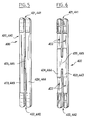
- la figure 1 précédemment décrite représente schématiquement, selon une vue partielle en coupe axiale longitudinale, un dispositif de coupure connu conforme à l'état de la technique,
- la figure 2 représente une vue en coupe axiale longitudinale similaire partielle d'un dispositif conforme à la présente invention,
- la figure 3 représente une vue en coupe transversale d'un jeu de contacts mobiles selon le plan de coupe référencé III-III sur la figure 2,
- la figure 4 représente une vue schématique en perspective d'un ressort conforme à la présente invention,
- les figures 5 et 6 représentent des vues en perspective de couteaux de contacts mobiles conformes à la présente invention,
- la figure 7 représente une vue partielle en perspective d'un arbre d'entraínement équipé de deux jeux de contacts mobiles conformes à la présente invention, et
- la figure 8 représente une vue schématique partielle en perspective d'un arbre conforme à la présente invention avant mise en place des moyens de contacts mobiles.
Claims (14)
- Dispositif de coupure électrique comprenant :de sorte que, par déplacement de l'arbre d'entraínement (300), le jeu de contacts mobiles (400) puisse être déplacé entre au moins deux positions : une position de fermeture dans laquelle les couteaux (420, 440) reposent par au moins une de leurs extrémités, sur le contact fixe (20), et une position d'ouverture dans laquelle les couteaux (420, 440) sont séparés du contact fixe (20),au moins un contact fixe (20),un arbre d'entraínement (300),au moins un jeu de contacts mobiles (400), porté par l'arbre d'entraínement (300), lequel jeu de contacts mobiles (400) comporte au moins deux couteaux généralement parallèles (420, 440), etdes moyens de sollicitation élastique (500), associés aux couteaux (420, 440) du jeu de contacts mobiles, pour solliciter ceux-ci en rapprochement,
caractérisé par le fait que les moyens de sollicitation élastique (500) sont formés d'au moins une pince adaptée pour maintenir les couteaux (420, 440) sur l'arbre d'entraínement (300) tout en autorisant un désaccouplement mécanique entre l'ensemble couteau (420, 440)/moyen de sollicitation élastique (500) et l'arbre d'entraínement (300), en position de fermeture. - Dispositif selon la revendication 1, caractérisé par le fait que l'arbre (300) est monté à rotation et qu'il est prévu deux contacts fixes (20), de préférence diamétralement opposés par rapport à l'axe de rotation (300), coopérant avec chaque jeu de contacts mobiles (400).
- Dispositif selon l'une des revendications 1 ou 2, caractérisé par le fait que les moyens de sollicitation élastique (500) associés à chaque jeu de contacts mobiles (400), sont formés de deux ensembles séparés disposés respectivement à proximité des extrémités des couteaux (420, 440).
- Dispositif selon l'une des revendications 1 à 3, caractérisé par le fait que l'arbre d'entraínement (300) porte plusieurs jeux de contacts mobiles (400) qui coopèrent respectivement avec une paire de contacts fixes (20).
- Dispositif selon l'une des revendications 1 à 4, caractérisé par le fait que chaque ensemble de sollicitation élastique est lui-même formé de deux ressorts (510) ayant globalement la forme d'un W.
- Dispositif selon la revendication 5, caractérisé par le fait que chaque ressort en W (510) comprend des éléments d'extrémité en C qui entourent partiellement un élément de couteau mobile (420, 440), pour interdire la séparation des couteaux (420, 440).
- Dispositif selon l'une des revendications 5 ou 6, caractérisé par le fait que chaque ressort (510) en W comprend un élément central en V élastique (512).
- Dispositif selon l'une des revendications 1 à 7, caractérisé par le fait que les moyens de sollicitation élastique (510) sont placés au moins partiellement dans des renfoncements (402) formés sur les couteaux mobiles (420, 440), pour interdire un déplacement entre ces moyens de sollicitation (510) et les couteaux (420, 440), dans le sens longitudinal de ces derniers.
- Dispositif selon l'une des revendications 1 à 8, caractérisé par le fait que chaque couteau (420, 440) est formé de deux lames (422, 423, 442, 443) globalement parallèles, reliées entre elles par un pont de matière (424, 444).
- Dispositif selon l'une des revendications 1 à 9, caractérisé par le fait qu'il comprend deux ensembles de sollicitation (500) disposés respectivement de part et d'autre d'un élément (330) de l'arbre (300) pour interdire un déplacement des couteaux (420, 440) par rapport à l'arbre dans un sens radial.
- Dispositif selon l'une des revendications 1 à 10, caractérisé par le fait que l'arbre (300) comprend un élément (330) disposé entre deux couteaux (420, 440), lequel élément intermédiaire de l'arbre (330) a une épaisseur axiale inférieure à celle des contacts fixes (20), de sorte qu'en position de fermeture, les couteaux (420, 440) de contact mobile soient séparés de l'arbre (300).
- Dispositif selon la revendication 11, caractérisé par le fait qu'en position d'ouverture, les couteaux (420, 440) reposent contre l'élément intermédiaire (330) de l'arbre (300), sous l'effet de la sollicitation élastique.
- Dispositif selon l'une des revendications 1 à 12, caractérisé par le fait que les moyens de sollicitation élastique (500) sont formés à base de bronze béryllium.
- Dispositif selon l'une des revendications 1 à 13, caractérisé par le fait que l'arbre d'entraínement (300) porte au moins trois jeux de contacts mobiles (400).
Applications Claiming Priority (2)
| Application Number | Priority Date | Filing Date | Title |
|---|---|---|---|
| FR0015906 | 2000-12-07 | ||
| FR0015906A FR2818004B1 (fr) | 2000-12-07 | 2000-12-07 | Perfectionnements aux dispositifs de coupure electrique |
Publications (2)
| Publication Number | Publication Date |
|---|---|
| EP1213730A1 true EP1213730A1 (fr) | 2002-06-12 |
| EP1213730B1 EP1213730B1 (fr) | 2010-01-27 |
Family
ID=8857360
Family Applications (1)
| Application Number | Title | Priority Date | Filing Date |
|---|---|---|---|
| EP01403122A Expired - Lifetime EP1213730B1 (fr) | 2000-12-07 | 2001-12-05 | Perfectionnements aux dispositifs de coupure élecrique |
Country Status (5)
| Country | Link |
|---|---|
| EP (1) | EP1213730B1 (fr) |
| AT (1) | ATE456854T1 (fr) |
| DE (1) | DE60141197D1 (fr) |
| ES (1) | ES2339917T3 (fr) |
| FR (1) | FR2818004B1 (fr) |
Cited By (1)
| Publication number | Priority date | Publication date | Assignee | Title |
|---|---|---|---|---|
| WO2014096509A1 (fr) | 2012-12-20 | 2014-06-26 | Abb Oy | Contact mobile d'interrupteur électrique |
Citations (3)
| Publication number | Priority date | Publication date | Assignee | Title |
|---|---|---|---|---|
| US3202775A (en) * | 1959-12-04 | 1965-08-24 | Gen Electric | Rotor type electric switch with resiliently mounted contact members |
| US3632935A (en) * | 1970-01-22 | 1972-01-04 | Gen Electric | Double blade rotor switch with blades insertable into rotatable shaft |
| US5969308A (en) * | 1998-04-02 | 1999-10-19 | Siemens Energy & Automation, Inc. | Rotary switch including spring biased knife blade contacts |
-
2000
- 2000-12-07 FR FR0015906A patent/FR2818004B1/fr not_active Expired - Lifetime
-
2001
- 2001-12-05 DE DE60141197T patent/DE60141197D1/de not_active Expired - Lifetime
- 2001-12-05 EP EP01403122A patent/EP1213730B1/fr not_active Expired - Lifetime
- 2001-12-05 ES ES01403122T patent/ES2339917T3/es not_active Expired - Lifetime
- 2001-12-05 AT AT01403122T patent/ATE456854T1/de not_active IP Right Cessation
Patent Citations (3)
| Publication number | Priority date | Publication date | Assignee | Title |
|---|---|---|---|---|
| US3202775A (en) * | 1959-12-04 | 1965-08-24 | Gen Electric | Rotor type electric switch with resiliently mounted contact members |
| US3632935A (en) * | 1970-01-22 | 1972-01-04 | Gen Electric | Double blade rotor switch with blades insertable into rotatable shaft |
| US5969308A (en) * | 1998-04-02 | 1999-10-19 | Siemens Energy & Automation, Inc. | Rotary switch including spring biased knife blade contacts |
Cited By (2)
| Publication number | Priority date | Publication date | Assignee | Title |
|---|---|---|---|---|
| WO2014096509A1 (fr) | 2012-12-20 | 2014-06-26 | Abb Oy | Contact mobile d'interrupteur électrique |
| EP2936525A4 (fr) * | 2012-12-20 | 2015-12-30 | Abb Oy | Contact mobile d'interrupteur électrique |
Also Published As
| Publication number | Publication date |
|---|---|
| FR2818004B1 (fr) | 2003-10-24 |
| EP1213730B1 (fr) | 2010-01-27 |
| DE60141197D1 (de) | 2010-03-18 |
| ES2339917T3 (es) | 2010-05-27 |
| FR2818004A1 (fr) | 2002-06-14 |
| ATE456854T1 (de) | 2010-02-15 |
Similar Documents
| Publication | Publication Date | Title |
|---|---|---|
| EP0373052A1 (fr) | Support pour ligne de transmission hyperfréquence, notamment du type triplaque | |
| EP0161120A1 (fr) | Combiné pour coupure en charge et le sectionnement visible d'un circuit électrique | |
| FR2888997A1 (fr) | Contact electrique adapte pour un rotulage | |
| EP1213730B1 (fr) | Perfectionnements aux dispositifs de coupure élecrique | |
| EP3993001B1 (fr) | Porte-contact mobile pour coupe-circuit et coupe-circuit comprenant un tel porte-contact mobile | |
| FR2503444A1 (fr) | Interrupteur a rupture brusque | |
| FR2553590A1 (fr) | Ensemble a balai en carbone | |
| WO2011135034A1 (fr) | Sectionneur de terre a encombrement reduit | |
| FR2859816A1 (fr) | Dispositif de coupure de courant electrique a discrimination complete d'etats | |
| EP0670579A1 (fr) | Dispositif de commutation pour ouvrir et fermer une ligne électrique | |
| EP0728906B1 (fr) | Moteur muni d'un dispositif de freinage par manque de courant | |
| EP1349187B1 (fr) | Dispositif de commutation pour ouvrir et fermer au moins une ligne électrique | |
| EP2061050B1 (fr) | Appareil électrique de coupure à contact(s) mobile(s) rotatif(s) | |
| FR2859815A1 (fr) | Dispositif de coupure de courant electrique a contact mobile en translation | |
| CH648953A5 (fr) | Interrupteur electrique a ressort de contact prearme. | |
| WO1999059177A1 (fr) | Appareil de coupure electrique pour installation electrique a basse tension alternative | |
| WO2024256359A1 (fr) | Contacteur comportant un moteur electrique et un systeme collecteur-balais | |
| EP1162637B1 (fr) | Dispositif de contact électrique sectionnable | |
| EP0779182A1 (fr) | Perfectionnement aux contacteurs electriques tournants | |
| EP4521440A1 (fr) | Dispositif de commutation électrique pour véhicule ferroviaire et véhicule ferroviaire comportant un tel dispositif | |
| FR3134661A1 (fr) | Architecture magnétique pour dispositif de connexion électrique | |
| FR2619659A1 (fr) | Connexion par broche avec torsion elastique | |
| FR2551262A1 (fr) | Interrupteur coaxial hf | |
| FR2662299A1 (fr) | Commutateur electrique pour vehicule automobile. | |
| EP0680849A1 (fr) | Contacteur électrique tournant comprenant des moyens de liaison perfectionnés pour conducteur électrique souple |
Legal Events
| Date | Code | Title | Description |
|---|---|---|---|
| PUAI | Public reference made under article 153(3) epc to a published international application that has entered the european phase |
Free format text: ORIGINAL CODE: 0009012 |
|
| AK | Designated contracting states |
Kind code of ref document: A1 Designated state(s): AT BE CH CY DE DK ES FI FR GB GR IE IT LI LU MC NL PT SE TR |
|
| AX | Request for extension of the european patent |
Free format text: AL;LT;LV;MK;RO;SI |
|
| 17P | Request for examination filed |
Effective date: 20021209 |
|
| AKX | Designation fees paid |
Designated state(s): AT BE CH CY DE DK ES FI FR GB GR IE IT LI LU MC NL PT SE TR |
|
| 17Q | First examination report despatched |
Effective date: 20080917 |
|
| GRAP | Despatch of communication of intention to grant a patent |
Free format text: ORIGINAL CODE: EPIDOSNIGR1 |
|
| GRAS | Grant fee paid |
Free format text: ORIGINAL CODE: EPIDOSNIGR3 |
|
| GRAA | (expected) grant |
Free format text: ORIGINAL CODE: 0009210 |
|
| AK | Designated contracting states |
Kind code of ref document: B1 Designated state(s): AT BE CH CY DE DK ES FI FR GB GR IE IT LI LU MC NL PT SE TR |
|
| REG | Reference to a national code |
Ref country code: GB Ref legal event code: FG4D Free format text: NOT ENGLISH |
|
| REG | Reference to a national code |
Ref country code: CH Ref legal event code: EP |
|
| REG | Reference to a national code |
Ref country code: IE Ref legal event code: FG4D |
|
| REF | Corresponds to: |
Ref document number: 60141197 Country of ref document: DE Date of ref document: 20100318 Kind code of ref document: P |
|
| REG | Reference to a national code |
Ref country code: ES Ref legal event code: FG2A Ref document number: 2339917 Country of ref document: ES Kind code of ref document: T3 |
|
| REG | Reference to a national code |
Ref country code: NL Ref legal event code: VDEP Effective date: 20100127 |
|
| PG25 | Lapsed in a contracting state [announced via postgrant information from national office to epo] |
Ref country code: AT Free format text: LAPSE BECAUSE OF FAILURE TO SUBMIT A TRANSLATION OF THE DESCRIPTION OR TO PAY THE FEE WITHIN THE PRESCRIBED TIME-LIMIT Effective date: 20100127 |
|
| PG25 | Lapsed in a contracting state [announced via postgrant information from national office to epo] |
Ref country code: NL Free format text: LAPSE BECAUSE OF FAILURE TO SUBMIT A TRANSLATION OF THE DESCRIPTION OR TO PAY THE FEE WITHIN THE PRESCRIBED TIME-LIMIT Effective date: 20100127 Ref country code: PT Free format text: LAPSE BECAUSE OF FAILURE TO SUBMIT A TRANSLATION OF THE DESCRIPTION OR TO PAY THE FEE WITHIN THE PRESCRIBED TIME-LIMIT Effective date: 20100527 |
|
| REG | Reference to a national code |
Ref country code: IE Ref legal event code: FD4D |
|
| PG25 | Lapsed in a contracting state [announced via postgrant information from national office to epo] |
Ref country code: FI Free format text: LAPSE BECAUSE OF FAILURE TO SUBMIT A TRANSLATION OF THE DESCRIPTION OR TO PAY THE FEE WITHIN THE PRESCRIBED TIME-LIMIT Effective date: 20100127 |
|
| PG25 | Lapsed in a contracting state [announced via postgrant information from national office to epo] |
Ref country code: IE Free format text: LAPSE BECAUSE OF FAILURE TO SUBMIT A TRANSLATION OF THE DESCRIPTION OR TO PAY THE FEE WITHIN THE PRESCRIBED TIME-LIMIT Effective date: 20100127 Ref country code: CY Free format text: LAPSE BECAUSE OF FAILURE TO SUBMIT A TRANSLATION OF THE DESCRIPTION OR TO PAY THE FEE WITHIN THE PRESCRIBED TIME-LIMIT Effective date: 20100127 Ref country code: GR Free format text: LAPSE BECAUSE OF FAILURE TO SUBMIT A TRANSLATION OF THE DESCRIPTION OR TO PAY THE FEE WITHIN THE PRESCRIBED TIME-LIMIT Effective date: 20100428 Ref country code: SE Free format text: LAPSE BECAUSE OF FAILURE TO SUBMIT A TRANSLATION OF THE DESCRIPTION OR TO PAY THE FEE WITHIN THE PRESCRIBED TIME-LIMIT Effective date: 20100127 |
|
| PLBE | No opposition filed within time limit |
Free format text: ORIGINAL CODE: 0009261 |
|
| STAA | Information on the status of an ep patent application or granted ep patent |
Free format text: STATUS: NO OPPOSITION FILED WITHIN TIME LIMIT |
|
| 26N | No opposition filed |
Effective date: 20101028 |
|
| PG25 | Lapsed in a contracting state [announced via postgrant information from national office to epo] |
Ref country code: DK Free format text: LAPSE BECAUSE OF FAILURE TO SUBMIT A TRANSLATION OF THE DESCRIPTION OR TO PAY THE FEE WITHIN THE PRESCRIBED TIME-LIMIT Effective date: 20100127 |
|
| PG25 | Lapsed in a contracting state [announced via postgrant information from national office to epo] |
Ref country code: MC Free format text: LAPSE BECAUSE OF NON-PAYMENT OF DUE FEES Effective date: 20101231 |
|
| REG | Reference to a national code |
Ref country code: CH Ref legal event code: PL |
|
| GBPC | Gb: european patent ceased through non-payment of renewal fee |
Effective date: 20101205 |
|
| PG25 | Lapsed in a contracting state [announced via postgrant information from national office to epo] |
Ref country code: CH Free format text: LAPSE BECAUSE OF NON-PAYMENT OF DUE FEES Effective date: 20101231 Ref country code: LI Free format text: LAPSE BECAUSE OF NON-PAYMENT OF DUE FEES Effective date: 20101231 |
|
| PG25 | Lapsed in a contracting state [announced via postgrant information from national office to epo] |
Ref country code: GB Free format text: LAPSE BECAUSE OF NON-PAYMENT OF DUE FEES Effective date: 20101205 |
|
| PG25 | Lapsed in a contracting state [announced via postgrant information from national office to epo] |
Ref country code: LU Free format text: LAPSE BECAUSE OF NON-PAYMENT OF DUE FEES Effective date: 20101205 |
|
| PG25 | Lapsed in a contracting state [announced via postgrant information from national office to epo] |
Ref country code: TR Free format text: LAPSE BECAUSE OF FAILURE TO SUBMIT A TRANSLATION OF THE DESCRIPTION OR TO PAY THE FEE WITHIN THE PRESCRIBED TIME-LIMIT Effective date: 20100127 |
|
| REG | Reference to a national code |
Ref country code: FR Ref legal event code: PLFP Year of fee payment: 15 |
|
| REG | Reference to a national code |
Ref country code: FR Ref legal event code: PLFP Year of fee payment: 16 |
|
| REG | Reference to a national code |
Ref country code: FR Ref legal event code: PLFP Year of fee payment: 17 |
|
| PGFP | Annual fee paid to national office [announced via postgrant information from national office to epo] |
Ref country code: DE Payment date: 20201209 Year of fee payment: 20 Ref country code: FR Payment date: 20201214 Year of fee payment: 20 Ref country code: IT Payment date: 20201210 Year of fee payment: 20 |
|
| PGFP | Annual fee paid to national office [announced via postgrant information from national office to epo] |
Ref country code: BE Payment date: 20201214 Year of fee payment: 20 |
|
| PGFP | Annual fee paid to national office [announced via postgrant information from national office to epo] |
Ref country code: ES Payment date: 20210107 Year of fee payment: 20 |
|
| REG | Reference to a national code |
Ref country code: DE Ref legal event code: R071 Ref document number: 60141197 Country of ref document: DE |
|
| REG | Reference to a national code |
Ref country code: BE Ref legal event code: MK Effective date: 20211205 |
|
| REG | Reference to a national code |
Ref country code: ES Ref legal event code: FD2A Effective date: 20220405 |
|
| PG25 | Lapsed in a contracting state [announced via postgrant information from national office to epo] |
Ref country code: ES Free format text: LAPSE BECAUSE OF EXPIRATION OF PROTECTION Effective date: 20211206 |