EP2936261B1 - Computerimplementiertes verfahren zum herstellen eines produktionsanlagenmodells - Google Patents
Computerimplementiertes verfahren zum herstellen eines produktionsanlagenmodells Download PDFInfo
- Publication number
- EP2936261B1 EP2936261B1 EP13818719.0A EP13818719A EP2936261B1 EP 2936261 B1 EP2936261 B1 EP 2936261B1 EP 13818719 A EP13818719 A EP 13818719A EP 2936261 B1 EP2936261 B1 EP 2936261B1
- Authority
- EP
- European Patent Office
- Prior art keywords
- module
- model
- container
- assigned
- grid field
- Prior art date
- Legal status (The legal status is an assumption and is not a legal conclusion. Google has not performed a legal analysis and makes no representation as to the accuracy of the status listed.)
- Active
Links
Images


Classifications
-
- G—PHYSICS
- G06—COMPUTING OR CALCULATING; COUNTING
- G06F—ELECTRIC DIGITAL DATA PROCESSING
- G06F30/00—Computer-aided design [CAD]
- G06F30/10—Geometric CAD
- G06F30/13—Architectural design, e.g. computer-aided architectural design [CAAD] related to design of buildings, bridges, landscapes, production plants or roads
-
- B—PERFORMING OPERATIONS; TRANSPORTING
- B01—PHYSICAL OR CHEMICAL PROCESSES OR APPARATUS IN GENERAL
- B01J—CHEMICAL OR PHYSICAL PROCESSES, e.g. CATALYSIS OR COLLOID CHEMISTRY; THEIR RELEVANT APPARATUS
- B01J19/00—Chemical, physical or physico-chemical processes in general; Their relevant apparatus
-
- G—PHYSICS
- G05—CONTROLLING; REGULATING
- G05B—CONTROL OR REGULATING SYSTEMS IN GENERAL; FUNCTIONAL ELEMENTS OF SUCH SYSTEMS; MONITORING OR TESTING ARRANGEMENTS FOR SUCH SYSTEMS OR ELEMENTS
- G05B19/00—Program-control systems
- G05B19/02—Program-control systems electric
- G05B19/418—Total factory control, i.e. centrally controlling a plurality of machines, e.g. direct or distributed numerical control [DNC], flexible manufacturing systems [FMS], integrated manufacturing systems [IMS] or computer integrated manufacturing [CIM]
- G05B19/41885—Total factory control, i.e. centrally controlling a plurality of machines, e.g. direct or distributed numerical control [DNC], flexible manufacturing systems [FMS], integrated manufacturing systems [IMS] or computer integrated manufacturing [CIM] characterised by modeling, simulation of the manufacturing system
-
- B—PERFORMING OPERATIONS; TRANSPORTING
- B01—PHYSICAL OR CHEMICAL PROCESSES OR APPARATUS IN GENERAL
- B01J—CHEMICAL OR PHYSICAL PROCESSES, e.g. CATALYSIS OR COLLOID CHEMISTRY; THEIR RELEVANT APPARATUS
- B01J2219/00—Chemical, physical or physico-chemical processes in general; Their relevant apparatus
- B01J2219/00002—Chemical plants
- B01J2219/00018—Construction aspects
- B01J2219/0002—Plants assembled from modules joined together
-
- B—PERFORMING OPERATIONS; TRANSPORTING
- B01—PHYSICAL OR CHEMICAL PROCESSES OR APPARATUS IN GENERAL
- B01J—CHEMICAL OR PHYSICAL PROCESSES, e.g. CATALYSIS OR COLLOID CHEMISTRY; THEIR RELEVANT APPARATUS
- B01J2219/00—Chemical, physical or physico-chemical processes in general; Their relevant apparatus
- B01J2219/00049—Controlling or regulating processes
- B01J2219/00243—Mathematical modelling
-
- G—PHYSICS
- G05—CONTROLLING; REGULATING
- G05B—CONTROL OR REGULATING SYSTEMS IN GENERAL; FUNCTIONAL ELEMENTS OF SUCH SYSTEMS; MONITORING OR TESTING ARRANGEMENTS FOR SUCH SYSTEMS OR ELEMENTS
- G05B2219/00—Program-control systems
- G05B2219/30—Nc systems
- G05B2219/32—Operator till task planning
- G05B2219/32085—Layout of factory, facility, cell, production system planning
-
- Y—GENERAL TAGGING OF NEW TECHNOLOGICAL DEVELOPMENTS; GENERAL TAGGING OF CROSS-SECTIONAL TECHNOLOGIES SPANNING OVER SEVERAL SECTIONS OF THE IPC; TECHNICAL SUBJECTS COVERED BY FORMER USPC CROSS-REFERENCE ART COLLECTIONS [XRACs] AND DIGESTS
- Y02—TECHNOLOGIES OR APPLICATIONS FOR MITIGATION OR ADAPTATION AGAINST CLIMATE CHANGE
- Y02P—CLIMATE CHANGE MITIGATION TECHNOLOGIES IN THE PRODUCTION OR PROCESSING OF GOODS
- Y02P90/00—Enabling technologies with a potential contribution to greenhouse gas [GHG] emissions mitigation
- Y02P90/02—Total factory control, e.g. smart factories, flexible manufacturing systems [FMS] or integrated manufacturing systems [IMS]
Definitions
- the present invention relates to a computer-implemented method for producing a two-dimensional system model of a modularly constructed production system for the production of a chemical product.
- the object of the invention is to provide a novel plant concept with which the effort associated with the production of various chemical products can be reduced significantly compared to the conventional procedure.
- the production system can also have two or more process containers that can be connected to one another in terms of production technology.
- the process containers are preferably transportable as a whole, which can be transported to a desired production location at which a correspondingly equipped production plant is to be set up, or can be transported away from this location after the desired production has been completed.
- This enables simple reuse of individual process containers at different production sites, which reduces production costs.
- a process container can have a housing that enables the process container to be transported easily, in which process modules suitable for carrying out an overall process or a specific process section are arranged and connected to one another in terms of production technology.
- a process container can, for example, have functionalities for heating, cooling, mixing, separating, pressure regulating, ventilating and / or venting, which enable a chemical reaction to be carried out and reaction conditions to be regulated.
- a process container can also be set up to independently carry out an overall process or a specific process section of production. In this context, autonomous means that the process section is carried out by means of the process container without any control and / or regulation of the Process section or part of it must be carried out by a facility away from the process container.
- At a production site at least one process container can be connected to a permanently installed communication network and / or to a supply network, preferably via standardized couplings, with which the process container can be supplied with material and / or energy and / or into which materials can be released, so that at least one chemical batch reaction and / or continuous production can be carried out essentially autonomously by means of the process container.
- the supply network can have a compressed air line for the supply of compressed air, a feed water line for the supply of water, an electrical line for the supply of electrical energy, a material line for the supply of starting materials and / or auxiliary materials and / or for the removal of products, by-products and / or waste materials, have a cooling line for supplying cold or for removing heat and / or a heating line for supplying heat or for removing cold.
- Various wired or wireless communication networks come into consideration as the communication network. A standardized exchange of information between the process containers connected to the communication network and / or with superordinate or subordinate devices can take place via the communication network.
- the process modules that can be connected to one another in terms of production technology can be arranged at least partially in a process container as intended.
- the overall arrangement of individual process modules per process container is minimized in terms of their space requirements and the material requirements required for their intended arrangement, so that in particular a maximum number of process modules can be arranged in a process container, which increases the variability of the equipping of a process container with process modules becomes.
- the container model and the module models are divided into equally sized grid fields.
- the grid fields are preferably square.
- the grid fields can be circular.
- a rectangular or elliptical design of the grid fields is possible, which, however, restricts the ability of the process modules to be arranged relative to the process container compared to a square or circular design of the grid fields.
- other types of polygonal or oval grid fields can also be used which are designed to be congruent to one another.
- the module properties and the occupancy properties represent boundary conditions with regard to the arrangement of the individual process modules relative to one another and relative to the process container.
- an optimal assignment of components of the process modules to the sections of the base area of the container and its surroundings that correspond to the grid fields of the container model takes place Size.
- a functional device can be a storage device for material and / or energy that can be connected to a local supply network.
- the occupancy properties of the container model are preferably selected from a group that includes at least the properties "cannot be occupied”, “can only be occupied with control room”, “can only be occupied with functional equipment”, “preferably not occupied”, “preferably occupied with control room” and "preferred occupied with functional device "includes.
- one of the properties “inside the container” or “outside the container” is assigned to each grid field of the container model. This represents a further criterion in the arrangement of the process modules relative to the process container. If a grid field of the container model has the property "inside the container”, then this grid field lies completely within the base area of the actual process container. If, on the other hand, a grid field of the container module has the property “outside the container”, then this grid field lies completely outside the base area of the actual process container, but completely within the base area of the actual environment of limited, predefinable size.
- Grid fields of a process module to which a functional device of the respective process module is assigned are preferably arranged on grid fields of the container model which have the property “inside the container”.
- each grid field of the container model is assigned an absolute, integer coordinate pair (x abs , y abs ), the origin of the absolute coordinate system on which it is based being arranged within the base area of the process container.
- An integral, relative coordinate pair (x rel , y rel ) is advantageously assigned to each grid field of a module model, the origin of the relative coordinate system on which it is based being arranged within the base area of the process module.
- the grid fields of a module model can also be easily individualized, which simplifies the assignment of properties to the individual grid fields of the respective module model.
- each module model is assigned a position in the absolute coordinate system which is defined by the position of the origin of the respective relative coordinate system within the absolute coordinate system.
- the ability of a module model to be arranged relative to the container model represents a first degree of freedom for the arrangement of the process modules to be optimized relative to the process container.
- Each module model is preferably assigned an alignment relative to the absolute coordinate system. If the container model and the module models are subdivided into square grid fields, for example, a module model can be aligned at the relative angles 0 °, 90 °, 180 ° or 270 ° relative to the absolute coordinate system. This relative alignability between the module model and the container model represents a second degree of freedom for the arrangement of the process modules to be optimized relative to the process container.
- connection variants between grid fields of different module models are determined, each connection variant having a value from a predeterminable value range, in particular from the value range ⁇ -100, ..., 100 ⁇ , is weighted.
- the connection variants are determined, for example, taking into account material and technical connections or relationships between the individual process modules to be arranged relative to a process container. Material relationships can result from given material and waste flows. Technical relationships can be based on distance requirements between incompatible devices of process modules.
- Connection variants which are weighted with a negative value lead to a maximization of the distance between grid fields belonging to these connection variants, and connection variants which are weighted with a positive value to a minimization of the distance between grid fields belonging to these connection variants.
- the distance can be maximized, for example, between incompatible technical devices.
- a minimization of the distance can serve, for example, to reduce the length of pipelines between technical devices of process modules.
- connection variant is selected which is weighted with the smallest positive value.
- the module models are preferably arranged in the container model taking into account all of these additional conditions.
- the module models are preferably arranged in the container model also taking into account all of these additional conditions.
- the arrangement of the module models in the container model assigned to the process container takes into account the arrangement of module models in a further container model assigned to a further process container, the further process container being arranged above, below or next to the process container.
- This configuration establishes further boundary conditions for the arrangement of process modules relative to a process container.
- the overall arrangement of process modules of a production plant comprising at least two process containers can be optimized accordingly.
- Another advantageous embodiment provides that a cuboid-shaped, standardized transport container, in particular according to DIN ISO 668, is used as the process container. This enables process containers equipped with process modules to be easily transported to the respective production sites using conventional standardized means of transport.
- the container model, the module models and the respective relative positions between the module models and the container model are displayed by a display device. This enables a simple control option for people involved in the planning of a corresponding production system.
- a method for optimizing an arrangement of at least two process modules of a modularly constructed production plant in a process container is created, whereby the aforementioned module properties, occupancy properties and conditions can be used in different combinations for this optimization.
- One goal of this optimization is to create an arrangement of process modules that is as space-saving as possible, with optimization functions preferably being formulated and used for this purpose. If a correspondingly optimized arrangement of process modules does not meet a predeterminable maximum number of the aforementioned conditions, the optimized arrangement is provided with a corresponding quality value in order, for example, to be able to compare different arrangements after corresponding optimizations.
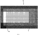
- Figure 1 shows a representation of an embodiment for the occupancy of the grid fields 1 of a two-dimensional container model 2 with occupancy properties.
- the container model 2 was generated for the base area 3 of a process container (not shown in greater detail) and the base area 4 of a container environment of a predetermined size that partially surrounds the process container.
- the container model 2 has been divided into square grid fields 1 of the same size.
- the base area 3 of the process container comprises 4 x 10 grid fields 1.
- the occupancy properties are selected from a group that includes the properties "cannot be used” (black), “can only be used with an operating room” (gray), “can only be used with functional equipment” (white ), “preferably not occupied” (black with hatching), “preferably occupied with control room” (gray with hatching) and “preferably occupied with functional equipment” (white with hatching).
- functional devices of process modules are preferably arranged inside the process container, whereas control rooms assigned to process modules can also be arranged outside the process container.
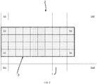
- Figure 2 shows an illustration of the assignment of the in Figure 1 shown container model 2 with absolute coordinate pairs (x abs , y abs ).
- the origin of the underlying absolute coordinate system is arranged within the base area 3 of the process container and marked with the absolute coordinate pair (0, 0).
- Each grid field 1 of the container model 2 is also assigned one of the properties “inside the container” (with hatching) or “outside the container” (white).
- FIG 3 shows an illustration of an exemplary embodiment for the occupation of the grid fields 4 of a module model 5 generated for the base area of a process module (not shown in detail) with module properties.
- the module model 5 is divided into square grid fields 4 of the same size, the dimensions of the grid fields 4 of the module model 5 being that of those of the grid fields 1 in the Figures 1 and 2 container model 2 shown corresponds.
- a relative pair of coordinates (x rel , y rel ) is assigned to each grid field 4 of the module model 5, the origin of the underlying relative coordinate system is arranged within the base area of the process module and marked with the relative coordinate pair (0, 0).
- Each grid field 4 of the module model 5 is a module property with regard to the occupancy of the respective grid field 4 with a functional device of the respective process module arranged above the section of the base area of the respective process module corresponding to this grid field 4 or with a section of the base area of the above the grid field 4 corresponding to this respective process module arranged, assigned to the process module control room.
- the module properties with regard to the occupation of the respective grid field 4 with a functional device of the respective process module arranged above the section of the base area of the respective process module corresponding to this grid field 4 are selected from a group that has the functional properties "material input” (relative coordinate pair (1, 2)) and “process aggregate” (relative coordinate pairs (0, 2), (0, 1), (1, 1), (0, 0) and (1, 0)).
- the module property "process equipment” can also be assigned to the grid field 4 with the relative coordinate pair (1, 2).
- the grid fields 4 with the relative coordinate pairs (-1, 2), (-1, 1), (-1, 0), (0, -1) and (1, -1) are assigned the module property "control room” accordingly .
- the grid fields 4 with the relative coordinate pairs (2, 1), (2, 0) and (2, -1)) are assigned the module property “material output”.
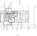
- FIG 4 shows a representation of the container model 2 with three module models 5 arranged therein.
- Each module model 5 is assigned a position in the absolute coordinate system which is defined by the position of the origin of the respective relative coordinate system within the absolute coordinate system.
- the process module 5 shown on the left has, for example, the position in the absolute coordinate system which is characterized by the absolute pair of coordinates (1, 0).
- each module model 5 is assigned an orientation relative to the absolute coordinate system. Since the container model 2 and the module models 5 are subdivided into square grid fields 1 and 4, a module model 5 can be oriented at the relative angles 0 °, 90 °, 180 ° or 270 ° relative to the absolute coordinate system.
- the process module 5 shown on the left is oriented at the relative angle 0 ° relative to the absolute coordinate system.
- the middle process module 5 is arranged at the position with the absolute coordinate pair (7, 0) and is oriented relative to the absolute coordinate system at the relative angle 270 °.
- the process module 5 shown on the right is arranged at the position with the absolute coordinate pair (9, 4) and oriented relative to the absolute coordinate system at the relative angle 0 °.
- connection variants between grid fields 4 of different module models 5, each of which has a functional device is assigned, determined, with each connection variant being weighted with a value from a predeterminable range of values, in particular from the range of values ⁇ -100, ..., 100 ⁇ .
- the grid fields 4 of the module model 5 shown on the left that are assigned the property “material output” can be connected to the grid field 4 of the module model 5 shown in the middle that is assigned the property “material input”.
- These material connections between the module model 5 shown on the left and the module model 5 shown in the middle is shown in FIG Figure 4 marked with the number 1. In Figure 4 these connection variants are indicated by arrows 6.
- connection variant according to which the grid field 4 with the relative coordinate pairs (2, 0) of the module model 5 shown on the left is connected to the grid field 4 with the relative coordinate pairs (0, 1) of the module model 5 shown in the middle, has the value 50 weighted.
- the two other connection variants indicated by an arrow 6 are each weighted with the value 100.
- connection variants between grid fields 4 of the module model 5 shown in the middle and assigned the property "material output” and the grid field assigned with the module property "material input” of the module model 5 shown on the right are shown in FIG Figure 4 marked with the number 2 and indicated by arrows 7.
- the connection variant, according to which the grid field 4 with the relative coordinate pairs (2, -1) of the module model 5 shown in the middle is connected to the grid field 4 with the relative coordinate pairs (0, 0) of the module model 5 shown on the right, is with the value 100 weighted.
- the other connection variant indicated by an arrow 7 is weighted with the value 50.
- FIG Figure 4 A connection variant between the grid fields 4 of the module model 5 shown on the left and assigned the property "material output” and the grid field of the module model 5 shown on the right with the module property "material input” is shown in FIG Figure 4 marked with the number 3 and indicated by the arrow 8.
- This connection variant according to which the grid field 4 with the relative coordinate pairs (1, 2) of the module model 5 shown on the left is connected to the grid field 4 with the relative coordinate pairs (0, 0) of the module model 5 shown on the right, is weighted with the value 50.
- FIG Figure 4 A connection variant between the grid fields 4 of the module model 5 shown on the left and assigned the property “process equipment” and the grid field of the module model 5 shown on the right with the module property “material input” is shown in FIG Figure 4 marked with the number 4 and indicated by the arrow 9.
- This connection variant according to which the grid field 4 with the relative coordinate pairs (0, 1) of the module model 5 shown on the left is connected to the grid field 4 with the relative coordinate pairs (0, 0) of the module model 5 shown on the right, is weighted with the value -100 .
- This connection variant thus relates to a repulsive relationship between the module model shown on the left and the module model shown on the right.
- connection variants are also determined and weighted accordingly. For reasons of clarity, however, other connection variants are not included Figure 4 shown.
- connection variants which, like the other connection variants mentioned above, are weighted with a positive value a minimization of the distance between these connection variants associated grid fields are preferably selected.
- Figure 5 shows a representation of the in Figure 4 shown container model 2 after optimizing the arrangement of the three module models 5 relative to each other and relative to the container model 2.
- the grid fields 4 of the module models 5, to which a functional device of the respective process module is assigned are all within the base area 3 of the process container not shown.
- Each module model 5 is assigned an optimized position in the absolute coordinate system, which is defined by the position of the origin of the respective relative coordinate system within the absolute coordinate system.
- the optimized position of the process module 5 shown on the left corresponds to that in FIG Figure 4 shown starting position of this module model 5 before performing the optimization.
- the middle process module 5 is arranged at the optimized position with the absolute coordinate pair (4, 1) and is oriented relative to the absolute coordinate system at the relative angle 270 °.
- the process module 5 shown on the right is arranged at the optimized position with the absolute coordinate pair (4, 3) and is oriented relative to the absolute coordinate system at the relative angle 180 °.
- This optimized arrangement of the module models 5 in the container model 2 is displayed by a display device not shown in detail.
Landscapes
- Engineering & Computer Science (AREA)
- Physics & Mathematics (AREA)
- Chemical & Material Sciences (AREA)
- Manufacturing & Machinery (AREA)
- General Physics & Mathematics (AREA)
- General Engineering & Computer Science (AREA)
- Quality & Reliability (AREA)
- Chemical Kinetics & Catalysis (AREA)
- Automation & Control Theory (AREA)
- Organic Chemistry (AREA)
- Geometry (AREA)
- Theoretical Computer Science (AREA)
- Computer Hardware Design (AREA)
- Architecture (AREA)
- Structural Engineering (AREA)
- Computational Mathematics (AREA)
- Mathematical Analysis (AREA)
- Mathematical Optimization (AREA)
- Pure & Applied Mathematics (AREA)
- Evolutionary Computation (AREA)
- Civil Engineering (AREA)
- Management, Administration, Business Operations System, And Electronic Commerce (AREA)
- General Factory Administration (AREA)
Priority Applications (1)
| Application Number | Priority Date | Filing Date | Title |
|---|---|---|---|
| PL13818719T PL2936261T3 (pl) | 2012-12-20 | 2013-12-18 | Realizowany komputerowo sposób wytwarzania modelu instalacji produkcyjnej |
Applications Claiming Priority (2)
| Application Number | Priority Date | Filing Date | Title |
|---|---|---|---|
| DE102012112775.1A DE102012112775A1 (de) | 2012-12-20 | 2012-12-20 | Computerimplementiertes Verfahren zum Herstellen eines Produktionsanlagenmodells |
| PCT/EP2013/077050 WO2014095972A1 (de) | 2012-12-20 | 2013-12-18 | Computerimplementiertes verfahren zum herstellen eines produktionsanlagenmodells |
Publications (2)
| Publication Number | Publication Date |
|---|---|
| EP2936261A1 EP2936261A1 (de) | 2015-10-28 |
| EP2936261B1 true EP2936261B1 (de) | 2021-01-20 |
Family
ID=49943332
Family Applications (1)
| Application Number | Title | Priority Date | Filing Date |
|---|---|---|---|
| EP13818719.0A Active EP2936261B1 (de) | 2012-12-20 | 2013-12-18 | Computerimplementiertes verfahren zum herstellen eines produktionsanlagenmodells |
Country Status (8)
| Country | Link |
|---|---|
| US (1) | US9870438B2 (pl) |
| EP (1) | EP2936261B1 (pl) |
| CN (1) | CN105009009B (pl) |
| DE (1) | DE102012112775A1 (pl) |
| DK (1) | DK2936261T3 (pl) |
| ES (1) | ES2857049T3 (pl) |
| PL (1) | PL2936261T3 (pl) |
| WO (1) | WO2014095972A1 (pl) |
Families Citing this family (1)
| Publication number | Priority date | Publication date | Assignee | Title |
|---|---|---|---|---|
| CN120577477B (zh) * | 2025-06-04 | 2025-11-04 | 北京雪迪龙科技股份有限公司 | 一种多智能传感器协同工作的气体监测分析系统 |
Family Cites Families (12)
| Publication number | Priority date | Publication date | Assignee | Title |
|---|---|---|---|---|
| US6470301B1 (en) * | 1999-10-08 | 2002-10-22 | Dassault Systemes | Optimization tool for assembly workcell layout |
| US6821052B2 (en) * | 2001-10-09 | 2004-11-23 | William Harrison Zurn | Modular, robotic road repair machine |
| ITUD20020072A1 (it) * | 2002-03-29 | 2003-09-29 | Univ Degli Studi Trieste | Procedimento per identificare le proprieta' meccaniche di un materiale |
| JP4381743B2 (ja) * | 2003-07-16 | 2009-12-09 | 独立行政法人理化学研究所 | 境界表現データからボリュームデータを生成する方法及びそのプログラム |
| KR100753537B1 (ko) * | 2006-06-09 | 2007-08-30 | 주식회사 아이너스기술 | 메시 데이터를 피처로 이용한 역설계 방법 |
| DE102007003192B4 (de) * | 2007-01-15 | 2012-04-26 | Fraunhofer-Gesellschaft zur Förderung der angewandten Forschung e.V. | Keramischer und/oder pulvermetallurgischer Verbundformkörper und Verfahren zu seiner Herstellung |
| GB2474602A (en) * | 2008-06-12 | 2011-04-20 | Spandan Choudury | A non-virtual-3d-video/photo generator rendering relative physical proportions of image in display medium and hence also of the display medium itself |
| DE102008041950A1 (de) * | 2008-09-10 | 2010-03-11 | Evonik Degussa Gmbh | System zur Bereitstellung einer universellen Infrastruktur für chemische Prozesse |
| DE202009000008U1 (de) * | 2009-01-08 | 2009-03-12 | Bachl, Armin | Haltevorrichtung für gebundenes Lesematerial |
| US8477137B2 (en) * | 2010-03-19 | 2013-07-02 | Yokogawa Electric Corporation | Method and apparatus for generating a material flow diagram for an industrial plant |
| US9430721B2 (en) * | 2014-02-13 | 2016-08-30 | Oce-Technologies B.V. | System for displaying printer information |
| US9441936B2 (en) * | 2014-07-29 | 2016-09-13 | Plethora Corporation | System and method for automated object measurement |
-
2012
- 2012-12-20 DE DE102012112775.1A patent/DE102012112775A1/de not_active Withdrawn
-
2013
- 2013-12-18 DK DK13818719.0T patent/DK2936261T3/da active
- 2013-12-18 ES ES13818719T patent/ES2857049T3/es active Active
- 2013-12-18 EP EP13818719.0A patent/EP2936261B1/de active Active
- 2013-12-18 PL PL13818719T patent/PL2936261T3/pl unknown
- 2013-12-18 WO PCT/EP2013/077050 patent/WO2014095972A1/de not_active Ceased
- 2013-12-18 CN CN201380067171.XA patent/CN105009009B/zh active Active
- 2013-12-18 US US14/653,913 patent/US9870438B2/en active Active
Non-Patent Citations (1)
| Title |
|---|
| None * |
Also Published As
| Publication number | Publication date |
|---|---|
| US9870438B2 (en) | 2018-01-16 |
| WO2014095972A1 (de) | 2014-06-26 |
| DK2936261T3 (da) | 2021-04-12 |
| EP2936261A1 (de) | 2015-10-28 |
| ES2857049T3 (es) | 2021-09-28 |
| CN105009009A (zh) | 2015-10-28 |
| CN105009009B (zh) | 2019-03-22 |
| US20150347636A1 (en) | 2015-12-03 |
| PL2936261T3 (pl) | 2021-06-28 |
| DE102012112775A1 (de) | 2014-07-10 |
Similar Documents
| Publication | Publication Date | Title |
|---|---|---|
| EP2916943B1 (de) | Produktionsanlage eines chemischen oder pharmazeutischen produktes | |
| DE112015005994B4 (de) | Softwareerzeugungseinrichtung | |
| DE102013201171A1 (de) | Verfahren und System zur Nutzung eines Industriegrundstücks | |
| EP2820356B1 (de) | Anlage zur belüftung von reinräumen | |
| DE102017125103A1 (de) | Einstellvorrichtung und einstellsystem zum konfigurieren von einstellungen für eine mehrzahl von maschinen | |
| EP3044644A2 (de) | Verfahren zur geführten umstellung einer behandlungsmaschine | |
| DE102013108910B4 (de) | Elektromagnetventilsteuervorrichtung | |
| EP2936261B1 (de) | Computerimplementiertes verfahren zum herstellen eines produktionsanlagenmodells | |
| EP2874029A1 (de) | Verfahren zum Betreiben einer zur Durchführung von wenigstens einer chemischen Reaktion eingerichteten Anlage | |
| EP3285995A1 (de) | Tablettiermaschine mit einer vorrichtung zur ausführung einer dashboard-anwendung | |
| EP1638028A2 (de) | Rechnergestützte Erzeugung und Änderungsmanagement für Bedienoberflächen | |
| EP2288969A1 (de) | Leitsystem einer anlage mit mehrstufiger modelloptimierung | |
| EP3083032B1 (de) | Verfahren zum betreiben einer modular aufgebauten produktionsanlage | |
| DE102021118796A1 (de) | Verfahren zur Produktionssteuerung | |
| DE19715494B4 (de) | Verfahren zur Erzeugung von Bedien- und Beobachtungsbildern für Anlagensteuersysteme | |
| DE19748528A1 (de) | Verfahren zur Erzeugung von Programmteilen für Steuerprogramme aus Bedien- und Beobachtungsbildern für Anlagensteuersysteme | |
| EP1750187B1 (de) | Regelungstechnische Einrichtung | |
| EP4426081A1 (de) | Verfahren zum bestücken von leiterplatten mittels mehrerer rüstungen auf einer bestückungslinie über einen kurzfristigen planungszeitraum | |
| DE102005020902A1 (de) | Verfahrenstechnische, insbesondere mikroverfahrenstechnische Anlage | |
| EP3483683A1 (de) | Autonomes system | |
| DE202025105226U1 (de) | Stromversorgungsschrank für Wasserstofferzeugung | |
| WO2024132627A1 (de) | Computer-implementiertes verfahren, system, computerprogramm und computerlesbares speichermedium zur herstellung zumindest eines produktes durch ein netzwerk von bearbeitungsanlagen | |
| Schoch | David Schoch | |
| DE102023201929A1 (de) | Verfahren und Vorrichtung zum Bereitstellen von Konfigurationsvorschlägen für eine Konfiguration eines modularen Produktionssystems | |
| WO2016083262A1 (de) | Verfahren zur konfiguration einer zur durchführung von wenigstens einer chemischen reaktion eingerichteten produktionsanlage |
Legal Events
| Date | Code | Title | Description |
|---|---|---|---|
| PUAI | Public reference made under article 153(3) epc to a published international application that has entered the european phase |
Free format text: ORIGINAL CODE: 0009012 |
|
| 17P | Request for examination filed |
Effective date: 20150720 |
|
| AK | Designated contracting states |
Kind code of ref document: A1 Designated state(s): AL AT BE BG CH CY CZ DE DK EE ES FI FR GB GR HR HU IE IS IT LI LT LU LV MC MK MT NL NO PL PT RO RS SE SI SK SM TR |
|
| AX | Request for extension of the european patent |
Extension state: BA ME |
|
| DAX | Request for extension of the european patent (deleted) | ||
| RAP1 | Party data changed (applicant data changed or rights of an application transferred) |
Owner name: BAYER AKTIENGESELLSCHAFT |
|
| STAA | Information on the status of an ep patent application or granted ep patent |
Free format text: STATUS: EXAMINATION IS IN PROGRESS |
|
| 17Q | First examination report despatched |
Effective date: 20191007 |
|
| GRAP | Despatch of communication of intention to grant a patent |
Free format text: ORIGINAL CODE: EPIDOSNIGR1 |
|
| STAA | Information on the status of an ep patent application or granted ep patent |
Free format text: STATUS: GRANT OF PATENT IS INTENDED |
|
| INTG | Intention to grant announced |
Effective date: 20200804 |
|
| GRAS | Grant fee paid |
Free format text: ORIGINAL CODE: EPIDOSNIGR3 |
|
| GRAA | (expected) grant |
Free format text: ORIGINAL CODE: 0009210 |
|
| STAA | Information on the status of an ep patent application or granted ep patent |
Free format text: STATUS: THE PATENT HAS BEEN GRANTED |
|
| AK | Designated contracting states |
Kind code of ref document: B1 Designated state(s): AL AT BE BG CH CY CZ DE DK EE ES FI FR GB GR HR HU IE IS IT LI LT LU LV MC MK MT NL NO PL PT RO RS SE SI SK SM TR |
|
| REG | Reference to a national code |
Ref country code: GB Ref legal event code: FG4D Free format text: NOT ENGLISH |
|
| REG | Reference to a national code |
Ref country code: CH Ref legal event code: EP |
|
| REG | Reference to a national code |
Ref country code: DE Ref legal event code: R096 Ref document number: 502013015463 Country of ref document: DE |
|
| REG | Reference to a national code |
Ref country code: AT Ref legal event code: REF Ref document number: 1356956 Country of ref document: AT Kind code of ref document: T Effective date: 20210215 |
|
| REG | Reference to a national code |
Ref country code: IE Ref legal event code: FG4D Free format text: LANGUAGE OF EP DOCUMENT: GERMAN |
|
| REG | Reference to a national code |
Ref country code: DK Ref legal event code: T3 Effective date: 20210406 |
|
| REG | Reference to a national code |
Ref country code: NL Ref legal event code: FP |
|
| REG | Reference to a national code |
Ref country code: SE Ref legal event code: TRGR |
|
| REG | Reference to a national code |
Ref country code: LT Ref legal event code: MG9D |
|
| PG25 | Lapsed in a contracting state [announced via postgrant information from national office to epo] |
Ref country code: LT Free format text: LAPSE BECAUSE OF FAILURE TO SUBMIT A TRANSLATION OF THE DESCRIPTION OR TO PAY THE FEE WITHIN THE PRESCRIBED TIME-LIMIT Effective date: 20210120 Ref country code: PT Free format text: LAPSE BECAUSE OF FAILURE TO SUBMIT A TRANSLATION OF THE DESCRIPTION OR TO PAY THE FEE WITHIN THE PRESCRIBED TIME-LIMIT Effective date: 20210520 Ref country code: HR Free format text: LAPSE BECAUSE OF FAILURE TO SUBMIT A TRANSLATION OF THE DESCRIPTION OR TO PAY THE FEE WITHIN THE PRESCRIBED TIME-LIMIT Effective date: 20210120 Ref country code: GR Free format text: LAPSE BECAUSE OF FAILURE TO SUBMIT A TRANSLATION OF THE DESCRIPTION OR TO PAY THE FEE WITHIN THE PRESCRIBED TIME-LIMIT Effective date: 20210421 Ref country code: FI Free format text: LAPSE BECAUSE OF FAILURE TO SUBMIT A TRANSLATION OF THE DESCRIPTION OR TO PAY THE FEE WITHIN THE PRESCRIBED TIME-LIMIT Effective date: 20210120 Ref country code: BG Free format text: LAPSE BECAUSE OF FAILURE TO SUBMIT A TRANSLATION OF THE DESCRIPTION OR TO PAY THE FEE WITHIN THE PRESCRIBED TIME-LIMIT Effective date: 20210420 Ref country code: NO Free format text: LAPSE BECAUSE OF FAILURE TO SUBMIT A TRANSLATION OF THE DESCRIPTION OR TO PAY THE FEE WITHIN THE PRESCRIBED TIME-LIMIT Effective date: 20210420 |
|
| PG25 | Lapsed in a contracting state [announced via postgrant information from national office to epo] |
Ref country code: RS Free format text: LAPSE BECAUSE OF FAILURE TO SUBMIT A TRANSLATION OF THE DESCRIPTION OR TO PAY THE FEE WITHIN THE PRESCRIBED TIME-LIMIT Effective date: 20210120 Ref country code: LV Free format text: LAPSE BECAUSE OF FAILURE TO SUBMIT A TRANSLATION OF THE DESCRIPTION OR TO PAY THE FEE WITHIN THE PRESCRIBED TIME-LIMIT Effective date: 20210120 |
|
| REG | Reference to a national code |
Ref country code: ES Ref legal event code: FG2A Ref document number: 2857049 Country of ref document: ES Kind code of ref document: T3 Effective date: 20210928 |
|
| PG25 | Lapsed in a contracting state [announced via postgrant information from national office to epo] |
Ref country code: IS Free format text: LAPSE BECAUSE OF FAILURE TO SUBMIT A TRANSLATION OF THE DESCRIPTION OR TO PAY THE FEE WITHIN THE PRESCRIBED TIME-LIMIT Effective date: 20210520 |
|
| REG | Reference to a national code |
Ref country code: DE Ref legal event code: R097 Ref document number: 502013015463 Country of ref document: DE |
|
| PG25 | Lapsed in a contracting state [announced via postgrant information from national office to epo] |
Ref country code: SM Free format text: LAPSE BECAUSE OF FAILURE TO SUBMIT A TRANSLATION OF THE DESCRIPTION OR TO PAY THE FEE WITHIN THE PRESCRIBED TIME-LIMIT Effective date: 20210120 Ref country code: EE Free format text: LAPSE BECAUSE OF FAILURE TO SUBMIT A TRANSLATION OF THE DESCRIPTION OR TO PAY THE FEE WITHIN THE PRESCRIBED TIME-LIMIT Effective date: 20210120 |
|
| PLBE | No opposition filed within time limit |
Free format text: ORIGINAL CODE: 0009261 |
|
| STAA | Information on the status of an ep patent application or granted ep patent |
Free format text: STATUS: NO OPPOSITION FILED WITHIN TIME LIMIT |
|
| PG25 | Lapsed in a contracting state [announced via postgrant information from national office to epo] |
Ref country code: RO Free format text: LAPSE BECAUSE OF FAILURE TO SUBMIT A TRANSLATION OF THE DESCRIPTION OR TO PAY THE FEE WITHIN THE PRESCRIBED TIME-LIMIT Effective date: 20210120 Ref country code: SK Free format text: LAPSE BECAUSE OF FAILURE TO SUBMIT A TRANSLATION OF THE DESCRIPTION OR TO PAY THE FEE WITHIN THE PRESCRIBED TIME-LIMIT Effective date: 20210120 |
|
| 26N | No opposition filed |
Effective date: 20211021 |
|
| PG25 | Lapsed in a contracting state [announced via postgrant information from national office to epo] |
Ref country code: AL Free format text: LAPSE BECAUSE OF FAILURE TO SUBMIT A TRANSLATION OF THE DESCRIPTION OR TO PAY THE FEE WITHIN THE PRESCRIBED TIME-LIMIT Effective date: 20210120 |
|
| PGFP | Annual fee paid to national office [announced via postgrant information from national office to epo] |
Ref country code: CZ Payment date: 20211129 Year of fee payment: 9 Ref country code: AT Payment date: 20211129 Year of fee payment: 9 Ref country code: SE Payment date: 20211126 Year of fee payment: 9 Ref country code: IE Payment date: 20211123 Year of fee payment: 9 Ref country code: DK Payment date: 20211209 Year of fee payment: 9 |
|
| PG25 | Lapsed in a contracting state [announced via postgrant information from national office to epo] |
Ref country code: SI Free format text: LAPSE BECAUSE OF FAILURE TO SUBMIT A TRANSLATION OF THE DESCRIPTION OR TO PAY THE FEE WITHIN THE PRESCRIBED TIME-LIMIT Effective date: 20210120 |
|
| PGFP | Annual fee paid to national office [announced via postgrant information from national office to epo] |
Ref country code: IT Payment date: 20211129 Year of fee payment: 9 Ref country code: BE Payment date: 20211203 Year of fee payment: 9 |
|
| PGFP | Annual fee paid to national office [announced via postgrant information from national office to epo] |
Ref country code: PL Payment date: 20211130 Year of fee payment: 9 |
|
| PG25 | Lapsed in a contracting state [announced via postgrant information from national office to epo] |
Ref country code: IS Free format text: LAPSE BECAUSE OF FAILURE TO SUBMIT A TRANSLATION OF THE DESCRIPTION OR TO PAY THE FEE WITHIN THE PRESCRIBED TIME-LIMIT Effective date: 20210520 |
|
| PGFP | Annual fee paid to national office [announced via postgrant information from national office to epo] |
Ref country code: TR Payment date: 20211215 Year of fee payment: 9 Ref country code: ES Payment date: 20220105 Year of fee payment: 9 |
|
| PG25 | Lapsed in a contracting state [announced via postgrant information from national office to epo] |
Ref country code: MC Free format text: LAPSE BECAUSE OF FAILURE TO SUBMIT A TRANSLATION OF THE DESCRIPTION OR TO PAY THE FEE WITHIN THE PRESCRIBED TIME-LIMIT Effective date: 20210120 |
|
| PG25 | Lapsed in a contracting state [announced via postgrant information from national office to epo] |
Ref country code: LU Free format text: LAPSE BECAUSE OF NON-PAYMENT OF DUE FEES Effective date: 20211218 |
|
| PGFP | Annual fee paid to national office [announced via postgrant information from national office to epo] |
Ref country code: NL Payment date: 20221114 Year of fee payment: 10 Ref country code: GB Payment date: 20221027 Year of fee payment: 10 |
|
| PGFP | Annual fee paid to national office [announced via postgrant information from national office to epo] |
Ref country code: CH Payment date: 20230101 Year of fee payment: 10 |
|
| PG25 | Lapsed in a contracting state [announced via postgrant information from national office to epo] |
Ref country code: HU Free format text: LAPSE BECAUSE OF FAILURE TO SUBMIT A TRANSLATION OF THE DESCRIPTION OR TO PAY THE FEE WITHIN THE PRESCRIBED TIME-LIMIT; INVALID AB INITIO Effective date: 20131218 |
|
| PG25 | Lapsed in a contracting state [announced via postgrant information from national office to epo] |
Ref country code: CY Free format text: LAPSE BECAUSE OF FAILURE TO SUBMIT A TRANSLATION OF THE DESCRIPTION OR TO PAY THE FEE WITHIN THE PRESCRIBED TIME-LIMIT Effective date: 20210120 |
|
| REG | Reference to a national code |
Ref country code: DK Ref legal event code: EBP Effective date: 20221231 |
|
| PG25 | Lapsed in a contracting state [announced via postgrant information from national office to epo] |
Ref country code: CZ Free format text: LAPSE BECAUSE OF NON-PAYMENT OF DUE FEES Effective date: 20221218 |
|
| REG | Reference to a national code |
Ref country code: SE Ref legal event code: EUG |
|
| REG | Reference to a national code |
Ref country code: AT Ref legal event code: MM01 Ref document number: 1356956 Country of ref document: AT Kind code of ref document: T Effective date: 20221218 |
|
| REG | Reference to a national code |
Ref country code: BE Ref legal event code: MM Effective date: 20221231 |
|
| PG25 | Lapsed in a contracting state [announced via postgrant information from national office to epo] |
Ref country code: SE Free format text: LAPSE BECAUSE OF NON-PAYMENT OF DUE FEES Effective date: 20221219 Ref country code: IE Free format text: LAPSE BECAUSE OF NON-PAYMENT OF DUE FEES Effective date: 20221218 Ref country code: AT Free format text: LAPSE BECAUSE OF NON-PAYMENT OF DUE FEES Effective date: 20221218 |
|
| PG25 | Lapsed in a contracting state [announced via postgrant information from national office to epo] |
Ref country code: BE Free format text: LAPSE BECAUSE OF NON-PAYMENT OF DUE FEES Effective date: 20221231 |
|
| PG25 | Lapsed in a contracting state [announced via postgrant information from national office to epo] |
Ref country code: IT Free format text: LAPSE BECAUSE OF NON-PAYMENT OF DUE FEES Effective date: 20221218 Ref country code: DK Free format text: LAPSE BECAUSE OF NON-PAYMENT OF DUE FEES Effective date: 20221231 |
|
| REG | Reference to a national code |
Ref country code: ES Ref legal event code: FD2A Effective date: 20240201 |
|
| PG25 | Lapsed in a contracting state [announced via postgrant information from national office to epo] |
Ref country code: ES Free format text: LAPSE BECAUSE OF NON-PAYMENT OF DUE FEES Effective date: 20221219 |
|
| PG25 | Lapsed in a contracting state [announced via postgrant information from national office to epo] |
Ref country code: MK Free format text: LAPSE BECAUSE OF FAILURE TO SUBMIT A TRANSLATION OF THE DESCRIPTION OR TO PAY THE FEE WITHIN THE PRESCRIBED TIME-LIMIT Effective date: 20210120 Ref country code: ES Free format text: LAPSE BECAUSE OF NON-PAYMENT OF DUE FEES Effective date: 20221219 |
|
| PG25 | Lapsed in a contracting state [announced via postgrant information from national office to epo] |
Ref country code: PL Free format text: LAPSE BECAUSE OF NON-PAYMENT OF DUE FEES Effective date: 20221218 |
|
| REG | Reference to a national code |
Ref country code: CH Ref legal event code: PL |
|
| REG | Reference to a national code |
Ref country code: NL Ref legal event code: MM Effective date: 20240101 |
|
| GBPC | Gb: european patent ceased through non-payment of renewal fee |
Effective date: 20231218 |
|
| PG25 | Lapsed in a contracting state [announced via postgrant information from national office to epo] |
Ref country code: NL Free format text: LAPSE BECAUSE OF NON-PAYMENT OF DUE FEES Effective date: 20240101 |
|
| PG25 | Lapsed in a contracting state [announced via postgrant information from national office to epo] |
Ref country code: MT Free format text: LAPSE BECAUSE OF FAILURE TO SUBMIT A TRANSLATION OF THE DESCRIPTION OR TO PAY THE FEE WITHIN THE PRESCRIBED TIME-LIMIT Effective date: 20210120 Ref country code: NL Free format text: LAPSE BECAUSE OF NON-PAYMENT OF DUE FEES Effective date: 20240101 |
|
| PG25 | Lapsed in a contracting state [announced via postgrant information from national office to epo] |
Ref country code: GB Free format text: LAPSE BECAUSE OF NON-PAYMENT OF DUE FEES Effective date: 20231218 |
|
| PG25 | Lapsed in a contracting state [announced via postgrant information from national office to epo] |
Ref country code: CH Free format text: LAPSE BECAUSE OF NON-PAYMENT OF DUE FEES Effective date: 20231231 |
|
| PG25 | Lapsed in a contracting state [announced via postgrant information from national office to epo] |
Ref country code: GB Free format text: LAPSE BECAUSE OF NON-PAYMENT OF DUE FEES Effective date: 20231218 Ref country code: CH Free format text: LAPSE BECAUSE OF NON-PAYMENT OF DUE FEES Effective date: 20231231 |
|
| PGFP | Annual fee paid to national office [announced via postgrant information from national office to epo] |
Ref country code: DE Payment date: 20251216 Year of fee payment: 13 |
|
| PGFP | Annual fee paid to national office [announced via postgrant information from national office to epo] |
Ref country code: FR Payment date: 20251222 Year of fee payment: 13 |