EP2936049B1 - Apparatus and method for measuring the profile depth of a tire - Google Patents
Apparatus and method for measuring the profile depth of a tire Download PDFInfo
- Publication number
- EP2936049B1 EP2936049B1 EP13786235.5A EP13786235A EP2936049B1 EP 2936049 B1 EP2936049 B1 EP 2936049B1 EP 13786235 A EP13786235 A EP 13786235A EP 2936049 B1 EP2936049 B1 EP 2936049B1
- Authority
- EP
- European Patent Office
- Prior art keywords
- tire
- image recording
- measuring
- profile
- light
- Prior art date
- Legal status (The legal status is an assumption and is not a legal conclusion. Google has not performed a legal analysis and makes no representation as to the accuracy of the status listed.)
- Active
Links
- 238000000034 method Methods 0.000 title claims description 51
- 238000005259 measurement Methods 0.000 claims description 107
- 230000003287 optical effect Effects 0.000 claims description 31
- 238000005286 illumination Methods 0.000 claims description 24
- 238000011156 evaluation Methods 0.000 claims description 22
- 238000003384 imaging method Methods 0.000 claims description 15
- 238000013459 approach Methods 0.000 claims description 8
- 238000005096 rolling process Methods 0.000 claims description 8
- 230000010354 integration Effects 0.000 claims description 5
- 230000002123 temporal effect Effects 0.000 claims description 3
- 238000001454 recorded image Methods 0.000 claims 2
- 238000004458 analytical method Methods 0.000 description 12
- 238000012360 testing method Methods 0.000 description 10
- 230000008901 benefit Effects 0.000 description 7
- 230000007613 environmental effect Effects 0.000 description 7
- 241001136792 Alle Species 0.000 description 5
- 238000009434 installation Methods 0.000 description 5
- 238000012546 transfer Methods 0.000 description 5
- 238000005299 abrasion Methods 0.000 description 4
- 238000010276 construction Methods 0.000 description 4
- 238000003745 diagnosis Methods 0.000 description 4
- 238000004364 calculation method Methods 0.000 description 3
- 230000001419 dependent effect Effects 0.000 description 3
- 230000000694 effects Effects 0.000 description 3
- 238000010191 image analysis Methods 0.000 description 3
- 230000005540 biological transmission Effects 0.000 description 2
- 230000007423 decrease Effects 0.000 description 2
- 238000013461 design Methods 0.000 description 2
- VVQNEPGJFQJSBK-UHFFFAOYSA-N Methyl methacrylate Chemical compound COC(=O)C(C)=C VVQNEPGJFQJSBK-UHFFFAOYSA-N 0.000 description 1
- 229920005372 Plexiglas® Polymers 0.000 description 1
- 230000009471 action Effects 0.000 description 1
- 230000004913 activation Effects 0.000 description 1
- 230000015572 biosynthetic process Effects 0.000 description 1
- 230000008859 change Effects 0.000 description 1
- 230000006835 compression Effects 0.000 description 1
- 238000007906 compression Methods 0.000 description 1
- 238000012937 correction Methods 0.000 description 1
- 238000010219 correlation analysis Methods 0.000 description 1
- 238000005520 cutting process Methods 0.000 description 1
- 238000001514 detection method Methods 0.000 description 1
- 230000004069 differentiation Effects 0.000 description 1
- 238000006073 displacement reaction Methods 0.000 description 1
- 238000009826 distribution Methods 0.000 description 1
- 238000005516 engineering process Methods 0.000 description 1
- 230000002349 favourable effect Effects 0.000 description 1
- 239000011521 glass Substances 0.000 description 1
- 230000001771 impaired effect Effects 0.000 description 1
- 230000003993 interaction Effects 0.000 description 1
- 230000002452 interceptive effect Effects 0.000 description 1
- 238000013507 mapping Methods 0.000 description 1
- 239000000463 material Substances 0.000 description 1
- 238000005457 optimization Methods 0.000 description 1
- 230000001151 other effect Effects 0.000 description 1
- 230000000704 physical effect Effects 0.000 description 1
- 230000008569 process Effects 0.000 description 1
- 230000009467 reduction Effects 0.000 description 1
- 230000000717 retained effect Effects 0.000 description 1
- 238000003860 storage Methods 0.000 description 1
- 230000003746 surface roughness Effects 0.000 description 1
- 239000000725 suspension Substances 0.000 description 1
- 230000001360 synchronised effect Effects 0.000 description 1
- 230000001960 triggered effect Effects 0.000 description 1
- 238000012800 visualization Methods 0.000 description 1
- 230000001755 vocal effect Effects 0.000 description 1
Images


Classifications
-
- G—PHYSICS
- G01—MEASURING; TESTING
- G01B—MEASURING LENGTH, THICKNESS OR SIMILAR LINEAR DIMENSIONS; MEASURING ANGLES; MEASURING AREAS; MEASURING IRREGULARITIES OF SURFACES OR CONTOURS
- G01B11/00—Measuring arrangements characterised by the use of optical techniques
- G01B11/22—Measuring arrangements characterised by the use of optical techniques for measuring depth
-
- G—PHYSICS
- G01—MEASURING; TESTING
- G01B—MEASURING LENGTH, THICKNESS OR SIMILAR LINEAR DIMENSIONS; MEASURING ANGLES; MEASURING AREAS; MEASURING IRREGULARITIES OF SURFACES OR CONTOURS
- G01B11/00—Measuring arrangements characterised by the use of optical techniques
- G01B11/24—Measuring arrangements characterised by the use of optical techniques for measuring contours or curvatures
- G01B11/245—Measuring arrangements characterised by the use of optical techniques for measuring contours or curvatures using a plurality of fixed, simultaneously operating transducers
-
- G—PHYSICS
- G01—MEASURING; TESTING
- G01B—MEASURING LENGTH, THICKNESS OR SIMILAR LINEAR DIMENSIONS; MEASURING ANGLES; MEASURING AREAS; MEASURING IRREGULARITIES OF SURFACES OR CONTOURS
- G01B11/00—Measuring arrangements characterised by the use of optical techniques
- G01B11/24—Measuring arrangements characterised by the use of optical techniques for measuring contours or curvatures
- G01B11/25—Measuring arrangements characterised by the use of optical techniques for measuring contours or curvatures by projecting a pattern, e.g. one or more lines, moiré fringes on the object
-
- G—PHYSICS
- G01—MEASURING; TESTING
- G01M—TESTING STATIC OR DYNAMIC BALANCE OF MACHINES OR STRUCTURES; TESTING OF STRUCTURES OR APPARATUS, NOT OTHERWISE PROVIDED FOR
- G01M17/00—Testing of vehicles
- G01M17/007—Wheeled or endless-tracked vehicles
- G01M17/02—Tyres
- G01M17/027—Tyres using light, e.g. infrared, ultraviolet or holographic techniques
Description
Die Erfindung betrifft eine Vorrichtung und ein Verfahren zur Messung der Profiltiefe wenigstens eines Reifens, insbesondere eines Kfz-Reifens.The invention relates to a device and a method for measuring the tread depth of at least one tire, in particular a motor vehicle tire.
Zur Messung der Profiltiefe von Reifen sind verschiedene Verfahren zur manuellen oder automatischen Profiltiefenmessung, mechanisch oder berührungslos messende Verfahren, sowie Verfahren zur Messung bei stehendem oder bei rollendem Fahrzeug bzw. Reifen bekannt.For measuring the tread depth of tires, various methods for manual or automatic tread depth measurement, mechanically or contactlessly measuring methods, and methods for measuring when the vehicle or tire is stationary or rolling are known.
Triangulationsverfahren mit Laserscannern zur Profiltiefenmessung in einem Rollenprüfstand werden beispielsweise in
Die
Es ist eine Aufgabe der Erfindung, eine verbesserte Vorrichtung und ein verbessertes Verfahren zur Messung der Profiltiefe eines Rades, insbesondere eines Kraftfahrzeuges, bereitzustellen, die für eine Vielzahl von Reifenbreiten geeignet sind, eine hohe Messgenauigkeit aufweisen und einfach zu bedienen bzw. auszuführen sind.It is an object of the invention to provide an improved device and an improved method for measuring the tread depth of a wheel, in particular a motor vehicle, which are suitable for a large number of tire widths, have a high measuring accuracy and are easy to operate and implement.
Die Aufgabe wird durch eine Vorrichtung nach dem unabhängigen Patentanspruch 1 und ein Verfahren nach dem unabhängigen Patentanspruch 9 gelöst. Die abhängigen Patentansprüche beschreiben mögliche Ausführungsformen einer erfindungsgemäßen Vorrichtung bzw. eines erfindungsgemäßen Verfahrens.The object is achieved by a device according to
Weitere Vorrichtungen und Verfahren zum Messen der Profiltiefe von Kraftfahrzeugreifen sind in
Die erfindungsgemäße Vorrichtung nach Anspruch 1 und das erfindungsgemäße Verfahren nach Anspruch 9 ermöglichen es, mit herkömmlichen Bauelementen, insbesondere mit marktgängigen kostengünstigen Flächenbildsensoren eine robuste und komfortable Messung der Profiltiefe von Kraftfahrzeugreifen mit nahezu beliebiger Breite zu realisieren.The device according to the invention according to
In einer Ausführungsform sind die Beleuchtungseinrichtungen der Messmodule so ausgebildet, dass sie ein Muster, das mehrere Lichtlinien umfasst, auf das Profil projizieren. Durch die Verwendung eines Musters mit mehreren Lichtlinien anstelle einer einzigen Lichtlinie lassen sich die Robustheit der Messung und die Genauigkeit der Messergebnisse noch weiter verbessern.In one embodiment, the lighting devices of the measuring modules are designed in such a way that they project a pattern comprising a plurality of lines of light onto the profile. By using a pattern with multiple lines of light instead of a single line of light, the robustness of the measurement and the accuracy of the measurement results can be further improved.
In einer Ausführungsform weisen die Beleuchtungseinrichtungen jeweils wenigstens ein diffraktives optisches Element ("DOE") auf, um das Lichtmuster zu erzeugen. Diffraktive optische Elemente können einfacher als konventionelle optische Elemente zur Erzeugung von Lichtlinienmustern ausgelegt werden, erzeugen eine gleichmäßige Intensitätsverteilung und nutzen, anders als beispielsweise optische Masken, die Energie des einfallenden Lichtstrahls fast vollständig aus.In one embodiment, the lighting devices each have at least one diffractive optical element (“DOE”) in order to generate the light pattern. Diffractive optical elements can be designed more easily than conventional optical elements for generating light line patterns, generate a uniform intensity distribution and, unlike, for example, optical masks, use the energy of the incident light beam almost completely.
Erfindungsgemäß sind die Beleuchtungseinrichtungen so ausgebildet, dass die einzelnen Lichtlinien kodiert sind, so dass sie eindeutig identifizierbar und insbesondere eindeutig einem der Messmodule zuordenbar sind. Die Identifizierbarkeit der einzelnen Lichtlinien ist notwendig, um in Verbindung mit einer großen Anzahl an Linien eine hohe Messgenauigkeit zu erreichen.According to the invention, the lighting devices are designed in such a way that the individual light lines are coded so that they can be clearly identified and, in particular, clearly assigned to one of the measuring modules. It is necessary to identify the individual light lines in order to achieve a high level of measurement accuracy in connection with a large number of lines.
Erfindungsgemäß sind die Lichtlinien zeitlich kodiert. Die Kodierung könnte auch eine räumliche, oder eine Kombination aus räumlicher und zeitlicher Kodierung umfassen. Dies ist aber nicht beansprucht. Eine räumliche Kodierung kann z.B. durch eine geeignet ausgebildetes diffraktives optisches Element, dass ein Linienmuster mit variierenden Linienabstand erzeugt, erreicht werden. Alternativ können auch die Breite der Linien, das Linienmuster und/oder die Linienform variiert werden.According to the invention, the light lines are time-coded. The coding could also include spatial coding or a combination of spatial and temporal coding. But this is not claimed. Spatial coding can e.g. by a suitably designed diffractive optical element that generates a line pattern with varying line spacing. Alternatively, the width of the lines, the line pattern and / or the line shape can also be varied.
Erfindungsgemäß wird eine zeitliche Kodierung der Linien vorgenommen, indem die Lichtlinien nicht gleichzeitig, sondern in einer vorgegebenen zeitlichen Abfolge auf das Reifenprofil projiziert werden.According to the invention, the lines are temporally coded in that the light lines are not projected onto the tire profile at the same time, but rather in a predetermined time sequence.
In einer Ausführungsform weisen die Bildaufnahmeeinrichtungen jeweils wenigsten ein optisches Element auf, das ausgebildet ist, um den Bildaufnahmebereich der Bildaufnahmeeinrichtung optisch zu verzerren, insbesondere in Laufrichtung des Reifens zu verdichten und/oder quer zur Laufrichtung des Reifens aufzuweiten. Durch ein derartiges optisches Element kann die vorgegebene Aufnahmefläche des Flächenbildsensors optimal ausgenutzt werden, so dass die Genauigkeit der Messung bei gleichbleibendem finanziellem Aufwand verbessert werden kann. Als optisches Element kann insbesondere eine Zylinderlinse zum Einsatz kommen.In one embodiment, the image recording devices each have at least one optical element which is designed to optically distort the image recording area of the image recording device, in particular to compress it in the running direction of the tire and / or to expand it transversely to the running direction of the tire. With such an optical element, the predetermined recording surface of the surface image sensor can be optimally used, so that the accuracy of the measurement can be improved with the same financial outlay. A cylinder lens, in particular, can be used as the optical element.
Alternativ oder zusätzlich kann die Ausnutzung der Aufnahmefläche des Bildsensors verbessert werden, indem der in der Regel rechteckige Flächenbildsensor um 90° gedreht angeordnet wird, so dass die Richtung des Reifenprofils, die parallel zur Laufrichtung des Reifens verläuft, in der eine höhere Auflösung erforderlich bzw. gewünscht ist, in der Richtung des Flächenbildsensors abgebildet wird, welche die höhere Anzahl an Bildpunkten aufweist.Alternatively or in addition, the utilization of the recording surface of the image sensor can be improved by arranging the generally rectangular surface image sensor rotated by 90 ° so that the direction of the tire profile, which runs parallel to the running direction of the tire, in which a higher resolution is required or desired, is imaged in the direction of the surface image sensor which has the higher number of pixels.
In einer Ausführungsform sind die Messmodule so ausgebildet, dass die Beleuchtungseinrichtungen und Bildaufnahmeeinrichtungen der verschiedenen Messmodule in der Laufrichtung des zu vermessenden Reifens versetzt zueinander, d.h. in der Laufrichtung des Reifens hintereinander, angeordnet sind. Durch eine derartige versetzte Anordnung wird zuverlässig verhindert, dass die Lichtlinien eines Messmoduls in den Messbereich eines benachbarten Messmoduls projiziert werden. In diesem Fall wäre es nicht notwendig, die Lichtlinien erfindungsgemäß so zu kodieren, dass die Lichtlinien der einzelnen Messmodule voneinander unterschieden werden können; daher können die Beleuchtungseinrichtungen der einzelnen Messmodule identisch aufgebaut sein. Darüber hinaus kann mit Hilfe von in Fahrtrichtung des Fahrzeugs hintereinander angeordneten Messmodulen die Geschwindigkeit des Fahrzeugs bestimmt werden, ohne dass dafür ein zusätzlicher Sensor benötigt wird.In one embodiment, the measuring modules are designed such that the lighting devices and image recording devices of the various measuring modules are offset from one another in the running direction of the tire to be measured, i.e. are arranged one behind the other in the running direction of the tire. Such an offset arrangement reliably prevents the light lines from one measuring module from being projected into the measuring area of an adjacent measuring module. In this case it would not be necessary to encode the light lines according to the invention in such a way that the light lines of the individual measuring modules can be differentiated from one another; therefore the lighting devices of the individual measuring modules can be constructed identically. In addition, with the help of measuring modules arranged one behind the other in the direction of travel of the vehicle, the speed of the vehicle can be determined without the need for an additional sensor.
In einer Ausführungsform sind die diffraktiven optischen Elemente einander unmittelbar benachbarter Messmodule verdreht gegeneinander angeordnet, so dass die einander überlappenden Lichtmuster, die von den Beleuchtungseinrichtungen einander unmittelbar benachbarter Messmodule erzeugt werden, unterschiedlich kodiert sind. Aufgrund der unterschiedlichen Kodierung können die Lichtmuster eindeutig einem der Messmodule zugeordnet werden. Ist z.B. in einem ersten Messmodul ein diffraktives optisches Element so ausgebildet und angeordnet, dass sich der Abstand der von ihm erzeugten Lichtlinien in Fahrtrichtung des Fahrzeugs von hinten nach vorne vergrößert, so ist ein identisch ausgebildetes diffraktives optisches Element eines unmittelbar benachbarten zweiten Messmoduls um 180° gedreht so angeordnet, dass der Abstand der Lichtlinien des von dem zweiten diffraktiven optischen Element erzeugten Lichtmusters in Fahrtrichtung des Fahrzeugs von hinten nach vorne abnimmt.In one embodiment, the diffractive optical elements of measuring modules that are directly adjacent to one another are arranged rotated relative to one another, so that the overlapping light patterns that are generated by the lighting devices of measuring modules that are directly adjacent to one another are coded differently. Due to the different coding, the light patterns can be clearly assigned to one of the measuring modules. Is e.g. In a first measuring module, a diffractive optical element is designed and arranged in such a way that the distance between the light lines it generates increases from back to front in the direction of travel of the vehicle, an identically designed diffractive optical element of an immediately adjacent second measuring module is rotated by 180 ° arranged that the distance between the light lines of the light pattern generated by the second diffractive optical element decreases in the direction of travel of the vehicle from the rear to the front.
Das diffraktive optische Element eines dem zweiten Messmodul benachbarten dritten Messmoduls ist dann wieder in der gleichen Ausrichtung wie das diffraktive optische Element des ersten Messmoduls angeordnet, das diffraktive optische Element eines vierten Messmoduls hat dann wieder die gleiche Ausrichtung, wie das diffraktive optische Element des zweiten Messmoduls usw. Auf diese Weise weisen einander überlappende Bereiche der Lichtmuster unmittelbar benachbarter Messmodule unterschiedliche Linienabstände auf, so dass die Lichtlinien über die gesamte Fahrzeugbreite eindeutig einem der Messmodule zugeordnet werden können.The diffractive optical element of a third measuring module adjacent to the second measuring module is then again arranged in the same orientation as the diffractive optical element of the first measuring module, the diffractive optical element of a fourth measuring module then again has the same orientation as the diffractive optical element of the second measuring module etc. In this way, overlapping areas of the light patterns of directly adjacent measuring modules have different line spacings, so that the light lines can be clearly assigned to one of the measuring modules over the entire width of the vehicle.
In einer Ausführungsform beträgt der Winkel zwischen der Richtung, in der die Beleuchtungseinrichtung die Lichtlinie auf den Reifen projiziert und der Bildaufnahmerichtung der zugehörigen Bildaufnahmeeinrichtung 20° bis 45°, insbesondere 40°. Ein Winkel im Bereich von 20° bis 45° stellt einen guten Kompromiss zwischen einer möglichst hohen Messgenauigkeit und einer möglichst geringen Abschattung, die beide mit einem größer werdenden Winkel zwischen der Projektionsrichtung der Beleuchtungseinrichtung und der Bildaufnahmerichtung der zugehörigen Bildaufnahmeeinrichtung zunehmen, dar.In one embodiment, the angle between the direction in which the lighting device projects the light line onto the tire and the image recording direction of the associated image recording device is 20 ° to 45 °, in particular 40 °. An angle in the range from 20 ° to 45 ° represents a good compromise between the highest possible measurement accuracy and the lowest possible shadowing, both of which increase with an increasing angle between the projection direction of the lighting device and the image recording direction of the associated image recording device.
In einer Ausführungsform beträgt der Öffnungswinkel der Bildaufnahmeeinrichtungen ± 20°. Unter Annahme einer Rillenbreite von 4 mm und einer Rillentiefe von 8 mm für einen typischen PKW-Neureifen hat sich eine Auslegung der Bildaufnahmeeinrichtung 18 mit einem effektiven Öffnungswinkel von ϕ = ± 20° unter Berücksichtigung der auftretenden Abschattung als gut geeignet erwiesen.In one embodiment, the opening angle of the image recording devices is ± 20 °. Assuming a groove width of 4 mm and a groove depth of 8 mm for a typical new car tire, a design of the
In einer Ausführungsform weist die Vorrichtung wenigstens einen zusätzlichen Sensor auf, der ausgebildet ist, um die Annäherung eines Reifens und/oder die Beleuchtung des Reifenprofils zu detektieren. Ein solcher zusätzlicher Sensor ermöglicht es, die Vorrichtung bei der Annäherung eines Fahrzeugs rechtzeitig in den Messzustand zu versetzen. Bei einem bekannten Abstand des zusätzlichen Sensors von der Messvorrichtung kann darüber hinaus die Annäherungsgeschwindigkeit des Fahrzeugs bestimmt werden. Auf diese Weise kann zuverlässig festgestellt werden, ob eine mögliche Fehlmessung ggf. auf eine zu hohe Fahrgeschwindigkeit des Fahrzeugs zurückzuführen ist.In one embodiment, the device has at least one additional sensor which is designed to detect the approach of a tire and / or the illumination of the tire profile. Such an additional sensor makes it possible to put the device into the measuring state in good time when a vehicle approaches. If the distance between the additional sensor and the measuring device is known, the approach speed of the vehicle can also be determined. In this way, it can be reliably determined whether a possible incorrect measurement is possibly due to an excessively high driving speed of the vehicle.
In einer Ausführungsform umfasst ein erfindungsgemäßes Verfahren, die Geschwindigkeit des Reifens zu bestimmen und das Verfahren abzubrechen, wenn eine zulässige Maximalgeschwindigkeit überschritten wird. Auf diese Weise können Fehlmessungen, die sich aus einer zu hohen Geschwindigkeit des Fahrzeugs ergeben, zuverlässig vermieden werden.In one embodiment, a method according to the invention comprises determining the speed of the tire and terminating the method if a permissible maximum speed is exceeded. In this way, incorrect measurements that result from an excessively high speed of the vehicle can be reliably avoided.
In einer Ausführungsform umfasst ein erfindungsgemäßes Verfahren zusätzlich, die ermittelte Profiltiefe mit einem vorgegebenen Grenzwert zu vergleichen und eine Warnung auszugeben, wenn die bestimmte Profiltiefe den vorgegebenen ersten Grenzwert unterschreitet. Auf diese Weise wird der Fahrer des Fahrzeugs zuverlässig gewarnt, wenn die Profiltiefe wenigstens eines Reifens die minimal zulässige Mindestprofiltiefe (erster Grenzwert) unterschreitet.In one embodiment, a method according to the invention additionally comprises comparing the determined profile depth with a predetermined limit value and to issue a warning if the specific profile depth falls below the specified first limit value. In this way, the driver of the vehicle is reliably warned if the profile depth of at least one tire falls below the minimum permissible minimum profile depth (first limit value).
In einer Ausführungsform umfasst ein erfindungsgemäßes Verfahren auch, die Profiltiefen der Reifen einer Achse miteinander zu vergleichen und eine Warnung auszugeben, wenn die Differenz zwischen den Profiltiefen der Reifen einer Achse einen vorgegebenen zweiten Grenzwert unterschreitet. Auf diese Weise wird der Fahrer des Fahrzeugs zuverlässig auf mögliche Fahrwerksprobleme hingewiesen, die zu einer unterschiedlichen Abnutzung der Reifen führen.In one embodiment, a method according to the invention also includes comparing the tread depths of the tires on an axle with one another and outputting a warning if the difference between the tread depths of the tires on an axle falls below a predetermined second limit value. In this way, the driver of the vehicle is reliably informed of possible chassis problems that lead to different tire wear.
In einer Ausführungsform umfasst ein erfindungsgemäßes Verfahren zusätzlich, Abbildungsparameter, die insbesondere die Beleuchtungsstärke der Beleuchtungseinrichtung und/oder die Integrationszeit der Bildaufnahmeeinrichtung umfassen, zu optimieren. Auf diese Weise wird erreicht, dass das Verfahren stets mit nahezu optimalen Abbildungsparametern durchgeführt wird, um eine möglichst hohe Qualität der Abbildung und in der Folge eine hohe Messgenauigkeit zu erreichen.In one embodiment, a method according to the invention additionally comprises the optimization of imaging parameters which in particular include the illuminance of the lighting device and / or the integration time of the image recording device. In this way it is achieved that the method is always carried out with almost optimal imaging parameters in order to achieve the highest possible quality of the imaging and, as a result, a high measurement accuracy.
Zusammenfassend weist die vorliegende Erfindung in den beschriebenen Ausführungsformen u. a. die folgenden Vorteile auf:
Durch den Einsatz mehrerer Messmodule auf jeder Fahrzeugseite, wird eine optimale Abbildungsgeometrie quer zur Laufrichtung des Reifens auch für große Messbreiten, z.B. PKW Spurweiten von 1200 mm bis 1800 mm, LKW Spurweiten von 1600 mm bis 2100 mm bis hin zu Transportern und LKW mit Doppelbereifung, gewährleistet, so dass das Verfahren und die Vorrichtung für PKW aller Art, aber auch für LKW, Busse und für mehrachsige Fahrzeuge einsetzbar sind.In summary, the present invention in the described embodiments has the following advantages, among others:
By using several measuring modules on each side of the vehicle, an optimal imaging geometry is achieved across the running direction of the tire, even for large measuring widths, e.g. passenger car track widths from 1200 mm to 1800 mm, truck track widths from 1600 mm to 2100 mm up to vans and trucks with double tires, guaranteed, so that the method and the device can be used for all types of cars, but also for trucks, buses and multi-axle vehicles.
Der vorgeschlagene modulare Aufbau ermöglicht eine einfache Bereitstellung von Messsystemen mit an den jeweiligen Bedarf angepassten lückenlosen Messbreiten beliebiger Größe.The proposed modular structure enables a simple provision of measuring systems with gapless measuring widths of any size, adapted to the respective requirements.
Die Erfindung stellt eine robuste Lösung zur Verfügung, die auch rauen Prüfbedingungen gewachsen ist. Die Vorrichtung weist keine bewegten Teile auf und vermeidet dadurch den Verschleiß an bewegten Teilen.The invention provides a robust solution that can also cope with harsh test conditions. The device has no moving parts and thus avoids wear and tear on moving parts.
Durch den vorgeschlagenen Einbau in die Fahrbahn, auf der Fahrbahn oder in eine Überfahrschwelle kann eine erfindungsgemäße Vorrichtung einfach an einer Vielzahl von Stellen, insb. auch in Einfahrten, z.B. von Werkstätten, Tankstellen, Drive-In, Drive-Thru, Parkplätzen, eingesetzt werden.As a result of the proposed installation in the roadway, on the roadway or in a drive-over threshold, a device according to the invention can easily be installed in a large number of places, especially in driveways, e.g. in workshops, gas stations, drive-in, drive-thru, parking lots.
Durch die Messung am rollenden Fahrzeug (Rad) wird eine für den Betreiber der Messstelle und für den Fahrer komfortable Lösung bereitgestellt.The measurement on the rolling vehicle (wheel) provides a comfortable solution for the operator of the measuring point and for the driver.
Die Messung findet von unten statt, wodurch potentiell störende Lichteinflüsse der Umwelt minimiert werden. Schwankendes Umgebungslicht (Tag, Nacht, Sonne, Wolken, ...) wird durch eine optimierte Beleuchtung kompensiert. Durch Anpassung der Beleuchtungsintensität und Integrationszeit werden Unter- und Überbelichtungen vermieden. Durch die Anordnung der Bildaufnahmeeinrichtung und auch der Beleuchtungseinrichtung in einem größeren Winkel zur Orthogonalen der Reifenoberfläche werden störende Reflexionen, welche die Messergebnisse verfälschen könnten, zuverlässig vermieden.The measurement takes place from below, which minimizes potentially disruptive light influences from the environment. Fluctuating ambient light (day, night, sun, clouds, ...) is compensated for by optimized lighting. By adjusting the lighting intensity and integration time, underexposure and overexposure can be avoided. By arranging the image recording device and also the lighting device at a larger angle to the orthogonal to the tire surface, disruptive reflections which could falsify the measurement results are reliably avoided.
Durch die Messung in der Reifenaufstandsfläche von unten durch einen Schlitz der Vorrichtung, werden Messfehler durch Profildeformation in der belasteten Aufstandsfläche vermieden.By measuring in the tire contact area from below through a slot in the device, measurement errors due to profile deformation in the loaded contact area are avoided.
Zusätzliche Korrekturverfahren aufgrund unterschiedlicher Messwinkel zur Orthogonalen der Reifenoberfläche bei unterschiedlichen Reifendurchmessern, sind nicht erforderlich.Additional correction procedures due to different measurement angles to the orthogonal of the tire surface for different tire diameters are not required.
Die Messung erfolgt quasi an einem statisch ruhenden Rad, dadurch werden Messfehler durch Bewegungsunschärfe vermieden.The measurement takes place on a statically stationary wheel, so measurement errors due to motion blur are avoided.
Es wird eine hohe Messgenauigkeit erreicht. Durch die Generierung einer großen Anzahl an Lichtlinien, die auf die Reifenoberfläche projiziert werden, wird eine hohe Abtastdichte erreicht, die eine sichere Erkennung von in das Profil integrierten Abriebindikatoren und von Objekten (z.B. verklemmte Steinchen) in den Profilrillen des Reifens, die das Messergebnis verfälschen könnten, ermöglicht. Durch eine Kodierung der Lichtlinien können die Bilder der reflektierten Lichtlinien auch bei kleinen Abständen zwischen den Lichtlinien zuverlässig zugeordnet und ausgewertet werden.A high measurement accuracy is achieved. By generating a large number of lines of light that are projected onto the tire surface, a high scanning density is achieved, which enables reliable detection of wear indicators integrated in the tread and of objects (e.g. jammed stones) in the tread grooves of the tire that falsify the measurement result could, made possible. By coding the light lines, the images of the reflected light lines can be reliably assigned and evaluated even with small distances between the light lines.
Die Visualisierung des Prüfergebnisses in Form einer Ampel und zusätzlich einer verbalen Handlungsempfehlung für den Fahrer erleichtert die Bedienbarkeit und vermeidet Fehler bei der Beurteilung der Messergebnisse.The visualization of the test result in the form of a traffic light and also a verbal recommendation for action for the driver makes it easier to use and avoids errors in the assessment of the measurement results.
Ausführungsbeispiele der Erfindung werden im Folgenden anhand der beigefügten Figuren näher erläutert.Embodiments of the invention are explained in more detail below with reference to the accompanying figures.
-
Figur 1 veranschaulicht in einer schematischen Darstellung das hier verwendete Messprinzip zur Profiltiefenmessung.Figure 1 shows in a schematic representation the measuring principle used here for profile depth measurement. -
Figur 2 zeigt eine schematische, perspektivische Ansicht eines Messplatzes zur Profiltiefenmessung.Figure 2 shows a schematic, perspective view of a measuring station for profile depth measurement. -
Figur 3 zeigt eine Anordnung zur Messung der Profiltiefe in einer schematischen Seitenansicht.Figure 3 shows an arrangement for measuring the profile depth in a schematic side view. -
Figur 4a zeigt einen Schnitt senkrecht zur Ebene der Fahrbahn durch das Zentrum des Reifens orthogonal zur Fahrtrichtung des Fahrzeugs.Figure 4a shows a section perpendicular to the plane of the road through the center of the tire orthogonal to the direction of travel of the vehicle. -
Figur 4b zeigt einen vergrößerten Ausschnitt ausFigur 4a .Figure 4b shows an enlarged sectionFigure 4a . -
Figur 5 zeigt einen Ausschnitt eines Reifens mit einer Profilrille und die geometrischen Zusammenhänge der Abschattung.Figure 5 shows a section of a tire with a tread groove and the geometrical relationships between the shading. -
Figur 6 zeigt einen Schnitt durch eine Vorrichtung zur Profiltiefenmessung mit vier Bildaufnahmeeinrichtungen.Figure 6 shows a section through a device for profile depth measurement with four image recording devices. -
Figuren 7a und 7b veranschaulichen eine verbesserte Ausnutzung eines Flächenbildsensors durch eine verzerrte optische Abbildung.Figures 7a and 7b illustrate an improved utilization of a surface image sensor by means of a distorted optical image. -
Figuren 8a und 8b veranschaulichen eine verbesserte Ausnutzung eines Flächenbildsensors durch eine alternative verzerrte optische Abbildung.Figures 8a and 8b illustrate an improved utilization of a surface image sensor through an alternative distorted optical image. -
Figur 9 ist ein Graph, der den Anteil der Fehlmessungen als Funktion der Anzahl der projizierten Lichtlinien zeigt.Figure 9 is a graph showing the proportion of incorrect measurements as a function of the number of projected lines of light. -
Figur 10 veranschaulicht eine Messung mit Lichtlinien, deren Abstände zu den jeweils benachbarten Linien variieren.Figure 10 illustrates a measurement with lines of light whose distances to the respective neighboring lines vary. -
Figur 11 zeigt eine schematische Ansicht einer Vorrichtung zur Messung der Profiltiefe in oder auf einer Fahrbahn quer zur Fahrtrichtung eines Kraftfahrzeuges.Figure 11 shows a schematic view of a device for measuring the tread depth in or on a roadway transverse to the direction of travel of a motor vehicle. -
Figur 12 zeigt eine seitliche Schnittansicht einer in einer Überfahrrinne angeordneten Vorrichtung zur Messung der Profiltiefe.Figure 12 shows a side sectional view of a device arranged in a drive-over channel for measuring the profile depth. -
Figur 13 zeigt eine Messvorrichtung mit vier in einer Überfahrrinne nebeneinander angeordneten identischen Messmodulen mit einem gemeinsamen Schlitz in der Aufsicht.Figure 13 shows a measuring device with four identical measuring modules arranged next to one another in a drive-over channel with a common slot in plan view. -
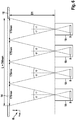
Figur 14 zeigt eine Messvorrichtung mit vier in einer Überfahrrinne nebeneinander angeordneten Messmodulen, die jeweils um 180° gedreht zueinander angeordnet sind, in der Aufsicht.Figure 14 shows a measuring device with four measuring modules arranged next to one another in a transfer channel, each of which is arranged rotated by 180 ° to one another, in a top view.
Ein Objektkoordinatensystem K ist so ausgerichtet, dass die Tiefenausdehnung des Profils parallel zur Z-Achse des Objektkoordinatensystems K ausgerichtet ist.An object coordinate system K is aligned in such a way that the depth of the profile is aligned parallel to the Z axis of the object coordinate system K.
Eine Beleuchtungseinrichtung 4 projiziert mindestens eine Lichtlinie 6 auf die mit einem Profil ausgebildete Lauffläche des Reifens 12. Eine Bildaufnahmeeinrichtung 18 ist mit einem in der
Die Schlitze 14 haben quer zur Fahrtrichtung F des Fahrzeugs 10 eine Ausdehnung (Länge) L, die mindestens der Breite der maximalen Aufstandsfläche der zu vermessenden Reifen 12 entspricht. Zusätzlich ist jedoch die Varianz der Spurweiten der zu vermessenden Fahrzeuge 10 zu berücksichtigen, um eine automatische Vermessung einer möglichst großen Zahl unterschiedlicher Fahrzeugtypen zu ermöglichen. Wenn die Messvorrichtung auch für Nutzfahrzeuge geeignet sein soll, ist insbesondere auch die Varianz der Spurweiten und Reifenbreiten von Transportern und LKW mit oder ohne Doppelbereifung zu berücksichtigen.The
Die Breite B der Schlitze 14 parallel zur Fahrtrichtung F ist zum einen deutlich kleiner zu wählen als die kleinste Aufstandsfläche typischer Reifen 12, zum anderen ist die Breite B der Schlitze 14 auch so zu wählen, dass durch die Überfahrt der Fahrkomfort nicht unangenehm beeinträchtigt wird.The width B of the
Die Schlitze 14 ermöglichen es, die Messung der Profiltiefe in einem unbelasteten Teilbereich der Lauffläche des zu prüfenden Reifens 12 durchzuführen. Dies hat den Vorteil, dass Messfehler, die aufgrund der durch die Radlast des Fahrzeugs 10 zwangsläufig hervorgerufenen Quetschung des Reifenmaterials in der Aufstandsfläche des Reifens 12 entstehen würden, vermieden werden.The
Darüber hinaus entspricht eine Messung im Bereich der Aufstandsfläche des Reifens 12 quasi einer Messung in Ruhelage, denn jeder Punkt der Lauffläche des Reifens 12 bewegt sich während des Abrollens auf der Fahrbahn 16 entlang einer Zykloiden mit der physikalischen Eigenschaft, dass seine Geschwindigkeit im Aufstandspunkt Null ist. Das hat den Vorteil, dass keine zusätzliche Messunsicherheit durch Bewegungsunschärfe vorhanden ist.In addition, a measurement in the area of the contact area of the
Ein weiterer Vorteil der Messung des aufstehenden Reifenprofils von unten durch einen Schlitz 14 besteht darin, dass durch die Karosserie des Fahrzeugs 10 und den Reifen 12 selbst das Umgebungslicht zu einem großen Teil abgeschattet wird und die Messung dadurch weitgehend unabhängig von wechselnden Umgebungsbedingungen (wie z.B. Tag, Nacht, Sonne, Wolken, ...) ist.Another advantage of measuring the upright tire profile from below through a
Für die Vermessung von PKW mit Spurweiten zwischen 1200 mm und 1800 mm in den Einfahrten von Werkstätten, Tankstellen oder Parkplätzen u.ä. unter Annahme einer maximalen Geschwindigkeit von 15 km/h hat sich zum Beispiel auf jeder Fahrzeugseite ein Schlitz 14 mit einer Länge L zwischen 500 mm und 700 mm und einer Breite B zwischen 30 mm und 50 mm als gut geeignet erwiesen. In der folgenden Beschreibung wird beispielhaft eine Schlitzlänge von L = 700 mm und eine Schlitzbreite von B = 50 mm angenommen.For the measurement of cars with gauges between 1200 mm and 1800 mm in the driveways of workshops, petrol stations or parking lots, etc. assuming a maximum speed of 15 km / h, for example, a
Die Beleuchtungseinrichtung 4 und die Bildaufnahmeeinrichtung 18 sind so angeordnet, dass der Messbereich der Bildaufnahmeeinrichtung dem Schlitz 14 in der Fahrbahn 16 entspricht. Das Messprinzip verlangt eine feste, unveränderliche Zuordnung zwischen dem Objekt (Reifen 12), der Beleuchtungseinrichtung 4 und der Bildaufnahmeeinrichtung 18. Durch die Vermessung des unbelasteten Teilbereichs der Reifenaufstandsfläche durch den Schlitz 14 in der Fahrbahn 16 ist gewährleistet, dass die Tiefenausdehnung des Reifenprofils, oder anders gesprochen, der Normalenvektor n des Reifens 12, für jeden Reifen 12 zum Zeitpunkt der Messung eine identische Ausrichtung aufweist. In dieser Anordnung ist das Messsystem auch zu kalibrieren.The
Die Genauigkeit des Lichtschnitt-Triangulationsverfahrens hängt von der Abbildungsgeometrie (Abbildungsmaßstab, Schnittwinkel der Raumstrahlen) und der als Punktmessgenauigkeit spx bezeichneten Güte der Linienpunktbestimmung ab. Die Punktmessgenauigkeit spx ist nicht nur abhängig von dem zur Detektion der Lichtlinie 6 eingesetzten Bildmessalgorithmus, sondern beinhaltet auch Messunsicherheiten, die durch die Oberflächentextur, Reflexionen oder Speckle-Effekte der Beleuchtung hervorgerufen werden. Unter optimalen Bedingungen und wenn sich die Breite der abgebildeten Lichtlinie 6 auf dem Flächenbildsensor 8 über mehrere Pixel erstreckt, kann durch Interpolation eine Subpixel-Punktmessgenauigkeit spx von 1/3 Pixel erreicht werden. Formel (1) ermöglicht eine Abschätzung der Tiefenmessgenauigkeit dZ eines optischen 3D-Triangulationssystems. ![]()
- mb:
- Abbildungsmaßstab zwischen Objektraum und Bildraum
- ps:
- Größe eines Sensorpixels in mm
- δ:
- Schnittwinkel zwischen der
Lichtebene 5und dem Abbildungsstrahl 7 am Objektpunkt P.
- mb:
- Image scale between object space and image space
- ps:
- Size of a sensor pixel in mm
- δ:
- Intersection angle between the
light plane 5 and theimaging beam 7 at the object point P.
Aus der Formel (1) ist ersichtlich, dass die Messgenauigkeit mit zunehmendem Winkel δ steigt. Aus praktischen Gründen, wie z.B. Beschränkungen des zur Verfügung stehenden Bauraums und der Gefahr, dass bei einem zu großen Winkel δ bei nicht ebenen Objekten Bereiche abgeschattet werden können, wie im Folgenden diskutiert wird, wird die Anordnung meist auf einen Winkel δ zwischen 20° und 45°, insbesondere 40° ausgelegt.It can be seen from formula (1) that the measurement accuracy increases with increasing angle δ. For practical reasons, e.g. Restrictions on the available installation space and the risk that, if the angle δ is too large, areas can be shaded in non-planar objects, as discussed below, the arrangement is usually set to an angle δ between 20 ° and 45 °, in particular 40 ° designed.
Die in der
Die Beleuchtungseinrichtung 4 wird so ausgerichtet, dass die Lichtlinien 6 parallel oder nahezu parallel zur Längsseite des Schlitzes 14 quer zur Fahrtrichtung F des Fahrzeugs 10 bzw. zur Laufrichtung des Reifens 12 auf dessen Lauffläche projiziert werden.The
Die vergrößerte Darstellung des Reifenprofils in der
Eine tabellarische Übersicht über die resultierenden Abschattungen 20 in Prozent der Rillenbreite als Funktion der Rillenbreite, der Profiltiefe und des Öffnungswinkels ϕ zeigt, dass die Abschattung 20 bei einer Rillentiefe von 8 mm auf maximal 27% begrenzt ist.
Unter der Annahme einer Rillenbreite von 4 mm und einer Rillentiefe von 8 mm eines typischen PKW-Neureifens hat sich eine Auslegung des Messsystems mit einem effektiven Öffnungswinkel von ϕ = ± 20° als gut geeignet erwiesen.Assuming a groove width of 4 mm and a groove depth of 8 mm in a typical new car tire, a design of the measuring system with an effective opening angle of ϕ = ± 20 ° has proven to be well suited.
Die Vermessung der betroffenen Profilrillen R1, R2, R3, R4, R5 wird durch die Abschattung 20 zwar eingeschränkt, kann aber durch zusätzliche Randbedingungen wieder verbessert werden:
Zum einen wird das Ausmaß der Abschattung 20 umso geringer, je geringer die Profiltiefe ist, d.h. je weiter das Profil abgefahren ist. Dadurch erhöht sich die Messgenauigkeit je mehr sich die Profiltiefe dem kritischen Warnwert der gesetzlich vorgegebenen Mindesttiefe nähert oder diesen unterschreitet.The measurement of the affected profile grooves R1, R2, R3, R4, R5 is restricted by the
On the one hand, the extent of the shadowing 20 becomes smaller, the smaller the profile depth, ie the further the profile is traversed. As a result, the measurement accuracy increases the closer the profile depth approaches the critical warning value of the legally prescribed minimum depth or falls below it.
Des Weiteren kann die Messgenauigkeit auch durch eine Erhöhung der Anzahl der auf das Profil projizierten Lichtlinien 6 gesteigert werden. Anstatt einen kompletten Rillengrund mit einer einzigen Lichtlinie 6 zu vermessen, können vier Lichtlinien 6 mit nur 25% messbarem Rillengrund theoretisch dasselbe Messergebnis für diese Rille erbringen. Aufgrund von zu erwartenden fehlerbehafteten Messungen ist eine deutlich größeren Anzahl von Lichtlinien 6 vorteilhaft, wie im Folgenden ausgeführt werden wird.Furthermore, the measurement accuracy can also be increased by increasing the number of light lines 6 projected onto the profile. Instead of measuring a complete groove base with a single light line 6, four light lines 6 with only 25% measurable groove base can theoretically produce the same measurement result for this groove. Due to expected error-prone Measurements, a significantly larger number of light lines 6 is advantageous, as will be explained below.
Typische PKW-Reifenprofile weisen in der Regel Längsrillen und schräg dazu verlaufende Nebenrillen auf, die systematisch wiederkehrende Blöcke mit einer Größe von 4 mm bis 8 mm bilden. Um Strukturen dieser Größenordnung im Bild der Bildaufnahmeeinrichtung 18 sicher detektieren zu können, wird eine Abbildung mit einer Auflösung von mindestens 2-3 Pixel/mm gewählt. Die Abbildung eines Messbereichs von 700 mm, definiert durch die Schlitzlänge L, erfordert bei 3 Pixel/mm demnach einen Flächenbildsensor 8 mit einer Auflösung von 2100 Pixeln zumindest in einer Richtung der Bildaufnahmefläche des Flächenbildsensors 8.Typical car tire profiles usually have longitudinal grooves and inclined secondary grooves which systematically form blocks with a size of 4 mm to 8 mm. In order to be able to reliably detect structures of this order of magnitude in the image of the
Auf dem Markt sind entsprechende Flächenbildsensoren 8 verfügbar. Die am Markt kostengünstig verfügbaren Flächenbildsensoren 8 haben jedoch den Nachteil, dass sie entweder relativ teuer sind oder Bilder nur mit niedrigen Aufnahmefrequenzen aufnehmen können. Ein typischer PKW-Reifen 12 hat einen Umfang von etwa 2000 mm und eine Latschlänge (Länge der Reifenaufstandsfläche) von etwa 100 mm. Bei einer Auslegung des Messsystems auf eine Überfahrgeschwindigkeit von maximal 15 km/h ist das Reifenprofil für die Bildaufnahmeeinrichtung 18 durch den Schlitz 14 für etwa 0,025 Sekunden sichtbar, so dass die Bildaufnahmeeinrichtung 18 auf eine Frequenz von mindestens 40 Bildern pro Sekunde ausgelegt sein muss.Corresponding
Erschwerend für den vorgesehenen Einsatz marktüblicher Flächenbildsensoren 8 für eine Profiltiefenmessung durch einen Schlitz 14 von unten kommt hinzu, dass zur Einhaltung des maximalen Öffnungswinkels ϕ von ± 20° mit Flächenbildsensoren 8 hoher Auflösung ein Abstand D zwischen dem Reifenprofil und dem Flächenbildsensor 8 (Aufnahmeabstand) von etwa 1 Meter erforderlich ist. Ein derartiger Aufnahmeabstand erfordert einen Bauraum entsprechender Größe oder andere konstruktive Maßnahmen.A further complicating factor for the intended use of commercially available
Alternativ zu einem großen Bauraum kann daher vorgesehen werden, mehrere relativ preiswerte Bildaufnahmeeinrichtungen 18, deren Flächenbildsensoren 8 zwar eine geringere Auflösung aber eine ausreichend hohe Aufnahmefrequenz haben, in Längsrichtung L des Schlitzes 14 quer zur Fahrtrichtung F des Fahrzeugs 10 nebeneinander anzuordnen.As an alternative to a large installation space, several relatively inexpensive
Mit der aus der optischen 3D-Messtechnik bekannten Formel (1) lässt sich die zu erwartende Tiefenmessgenauigkeit für die Profilmesseinrichtung wie folgt abschätzen: ![]()
![]()
Diese Abschätzung zeigt, dass mit einer Vorrichtung, wie sie in der
Aus dem Format der Flächenbildsensoren 8, dem Öffnungswinkel ϕ = ± 20° und der Aufnahmeentfernung D1 = 240 mm ergibt sich ein rechteckiges Objektfenster 24 der Größe 175 mm x 130 mm. Da die Breite B des Schlitzes 14 nur 50 mm beträgt, werden, wie in der
Diesem Nachteil kann durch eine zusätzliche, lineare Optik 22, wie z.B. einer Zylinderlinse 22, die im Strahlengang 7, zwischen dem Flächenbildsensor 8 und dem Schlitz 14 angeordnet ist und die nur in einer Raumrichtung Brechkraft besitzt, abgeholfen werden.This disadvantage can be avoided by an additional,
Ein alternatives Konzept sieht vor, das nicht quadratische Bildformat des Flächenbildsensors 8 der Bildaufnahmeeinrichtung 18 durch eine Drehung um 90° mit seiner höheren Auflösung von 640 Pixel für die Messung der kleineren Objektfensterbreite B zu verwenden. Dadurch nimmt die Auflösung in Richtung der Breite B des Schlitzes 14 auf etwa 13 Pixel/mm zu.An alternative concept provides that the non-square image format of the
Ein weiteres Konzept sieht vor, den Aufnahmeabstand D1 zum Beispiel auf einen Aufnahmeabstand D2 < D1 zu verringern, so dass das Objektfenster 24 nur noch etwa 50 mm x 37 mm beträgt und die 50 mm der Breite B des Objektfensters 24 auf die 640 Pixel des Flächenbildsensors 8 abgebildet werden, wie in der
Auf diese Weise wird eine noch höhere Auflösung für die Tiefenmessgenauigkeit und eine deutlich höhere Messgenauigkeit erreicht, die sich gemäß Formel (2) durch einen verringerten Abbildungsmaßstab abschätzen lässt. Die dabei reduzierte Größe des Objektfensters 24 in der Richtung quer zur Fahrtrichtung F kann, wie in der
Ein weiterer Vorteil der in der
Auch eine Kombination aus einer Komprimierung des Bildes in einer Richtung parallel zur Fahrtrichtung F gemäß
In einem in den Figuren nicht gezeigten Ausführungsbeispiel wird die normale Abbildungsoptik der Bildaufnahmeeinrichtung 18 mit der linearen Optik 22, 23 zu einem gemeinsamen optischen System zusammengefasst, das in den Richtungen parallel und quer zur Fahrtrichtung F eine unterschiedliche Brechkraft aufweist. Da die Aufnahmeeinrichtung 18 in diesem Fall mit nur einem einzigen Objektiv versehen wird, das die Eigenschaften der Bildaufnahmeeinrichtung 18 und der linearen Optik 22, 23 miteinander vereint, vereinfacht sich die Konstruktion der Bildaufnahmeeinrichtung 18.In an exemplary embodiment not shown in the figures, the normal imaging optics of the
Die Genauigkeit und die Robustheit der Profiltiefenmessung können durch eine Erhöhung der Anzahl der auf das Profil projizierten Lichtlinien 6 weiter gesteigert werden.The accuracy and robustness of the profile depth measurement can be increased further by increasing the number of light lines 6 projected onto the profile.
In den Profilgrund der Reifenlauffläche sind gemäß einer gesetzlichen Richtlinie sogenannte Abriebindikatoren integriert, die sich gegenüber dem Rillengrund um den Betrag der gesetzlich vorgeschriebenen minimalen Profiltiefe erheben. Durch diese Erhebungen sowie durch andere Störobjekte wie Schmutz oder verklemmte Steinchen kann die Messung verfälscht werden, wenn die fehlerhaften Messungen nicht robust als Ausreißer erkannt und eliminiert werden. Robuste Schätzer zur Effizienzsteigerung von Schätzverfahren, wie zum Beispiel der RANSAC-Algorithmus, sind aus der mathematischen Statistik bekannt. Aufgrund der zum Teil vorgeschriebenen Anordnung der Abriebindikatoren und ihrer typischen Ausdehnung von etwa 6 mm bis 10 mm in Laufrichtung können die Messwerte im vorgesehen Messfenster mit einer Schlitzbreite von 50 mm einen theoretischen Ausreißeranteil von 20% aufweisen. Abhängig von der im gewissen Umfang vom Reifenhersteller frei wählbaren Anordnung der Abriebindikatoren und der zufälligen Position der Abriebindikatoren im Bereich des Schlitzes 14 zum Zeitpunkt der Messung, kann bei nur wenigen Linien der Ausreißeranteil jedoch im günstigen Fall einen Wert von 0% und im ungünstigen Fall einen Wert von 100% einnehmen, so dass eine Erkennung, ob Ausreißer vorliegen bzw. welche Messwerte als Ausreißer zu werten sind, gar nicht bzw. nur mit großer Unsicherheit möglich ist.In accordance with a legal guideline, so-called abrasion indicators are integrated into the base of the tread of the tire tread, which increase compared to the base of the groove by the amount of the legally prescribed minimum tread depth. These surveys and other interfering objects such as dirt or jammed stones can falsify the measurement if the incorrect measurements are not robustly identified as outliers and eliminated. Robust estimators for increasing the efficiency of estimation methods, such as the RANSAC algorithm, are known from mathematical statistics. Due to the sometimes prescribed arrangement of the abrasion indicators and their typical extension of around 6 mm to 10 mm in the running direction, the measured values in the provided measurement window with a slot width of 50 mm can have a theoretical outlier proportion of 20%. Depending on the freely selectable arrangement of the abrasion indicators by the tire manufacturer to a certain extent and the random position of the abrasion indicators in the area of the
In der
Der Erfolg des Ausreißertests ist auch abhängig von einem vorzugebenden Grenzwert, bis zu welcher Grenze ein Messwert nicht als Ausreißer gilt. Je kleiner der Grenzwert gewählt werden kann, desto zuverlässiger können die Ausreißer detektiert werden, einhergehend mit weniger Rechenaufwand, je genauer der theoretische Ausreißeranteil a priori bekannt ist.The success of the outlier test also depends on a limit value to be specified, up to which limit a measured value is not considered an outlier. The smaller the limit value that can be selected, the more reliably the outliers can be detected, along with less computational effort, the more precisely the theoretical outlier portion is known a priori.
Praktische Messungen haben ergeben, dass mindestens dreißig Lichtlinien 6 empfehlenswert sind, um eine absolute Messgenauigkeit von ≤ ± 0.2 mm bei einer Robustheit von ≥ 98% zu gewährleisten.Practical measurements have shown that at least thirty lines of light 6 are recommended in order to ensure an absolute measurement accuracy of ≤ ± 0.2 mm with a robustness of ≥ 98%.
Bei einer hohen Anzahl n von Lichtlinien 6 geht die lokale, linienweise Abtastung in eine flächenhafte Abtastung über, die zusätzliche Möglichkeiten zur Messung und Bewertung des Reifenprofils eröffnet. Ein weiterer Vorteil einer hohen Abtastdichte ist, dass die Abriebindikatoren sicher als solche detektiert und gemessen werden können, weil dadurch die relative Messgenauigkeit und Zuverlässigkeit der Ergebnisse verbessert wird. Hilfreich ist dazu die Kenntnis, dass die Abriebindikatoren für die meisten Reifenprofile in Laufrichtung etwa 10 mm Ausdehnung aufweisen, die bei einer hohen Anzahl von Linien 6 einfacher segmentiert werden können. Weiterhin besteht auch die Möglichkeit, Hinweise auf Schäden wie Auswaschungen oder Sägezahnbildung im Profil geben zu können oder die einseitige Abnutzung des Profils als Folge eines fehlerhaften Radsturzes zu erkennen. Darüber hinaus kann die hohe Abtastdichte dazu verwendet werden, um anhand der unterschiedlichen Profilstrukturen zu unterscheiden, ob es sich um einen Sommer-, Winter- oder Alljahresreifen handelt.In the case of a high number n of light lines 6, the local, line-by-line scanning changes into area-wide scanning, which opens up additional possibilities for measuring and evaluating the tire profile. A further advantage of a high scanning density is that the wear indicators can be reliably detected and measured as such, because this improves the relative measurement accuracy and the reliability of the results. It is helpful to know that the wear indicators for most tire profiles have an extension of about 10 mm in the running direction, which can be segmented more easily with a large number of lines 6. Furthermore, there is also the possibility of being able to provide information on damage such as washouts or sawtooth formation in the profile or to recognize the one-sided wear of the profile as a result of a faulty wheel camber. In addition, the high scanning density can be used to distinguish on the basis of the different profile structures whether it is a summer, winter or all-season tire.
Die Breite einer Lichtlinie 6 im Bild auf dem Flächenbildsensor 8 ist abhängig von der Qualität der abbildenden Optiken der Beleuchtungseinrichtung 4 und der Bildaufnahmeeinrichtung 18, von der Oberflächenrauhigkeit und von weiteren Effekten wie Streulicht und Speckle. Abbildungseffekte können deshalb durchaus toleriert werden, wenn sie systematisch zu einer Linienverbreiterung beitragen. Wie bereits erwähnt, ist die Breite einer abgebildeten Lichtlinie 6 entscheidend für die Linienpunktmessgenauigkeit. Aus der Anforderung einer optimalen Linienbreite von ca. fünf Pixel zur Linienpunktmessung im Subpixel-Bereich und unter Annahme eines minimalen Abstandes von einem Pixel zur Trennung der Lichtlinien 6 lässt sich herleiten, dass theoretisch maximal 106 Lichtlinien 6 möglich sind, wenn, wie im Beispiel beschrieben, auf dem Flächenbildsensor 8 640 Pixel zur Verfügung stehen.The width of a line of light 6 in the image on the
Von der objektseitigen Betrachtung her ist die Generierung von Lichtlinien 6 mit einer Linienbreiten von 0,3 mm oder weniger technisch möglich, so dass unter Annahme eines Linienabstandes von beispielsweise 0,2 mm etwa einhundert Lichtlinien 6 in einen Schlitz 14 mit einer Breite B von 50 mm projiziert werden können.When viewed from the object side, it is technically possible to generate lines of light 6 with a line width of 0.3 mm or less, so that assuming a line spacing of, for example, 0.2 mm, approximately one hundred lines of light 6 into a
Die geeignete Breite der projizierten Lichtlinien 6 ist deshalb abhängig von der Abbildungsgeometrie und systemimmanenter Abbildungsfehler und wird so festgelegt, dass durch alle Einflussfaktoren eine Linienbreite im Bild auf dem Flächenbildsensor 8 von etwa fünf Pixeln entsteht und mindestens dreißig Lichtlinien 6 abgebildet werden können.The suitable width of the projected light lines 6 is therefore dependent on the imaging geometry and system-immanent imaging errors and is determined in such a way that all influencing factors result in a line width in the image on the
Bei einer hohen Anzahl von Lichtlinien 6 und sich einem daraus ergebenden geringen Abstand zwischen den einzelnen Lichtlinien 6 ist, abhängig von der Tiefenausdehnung des Objekts und vom Winkel δ zwischen der Projektionsrichtung der Beleuchtungseinrichtung 4 und der Aufnahmerichtung der Bildaufnahmeeinrichtung 18 am Objekt, eine eindeutige Zuordnung des Bildes einer Lichtlinie 6a auf dem Flächenbildsensor 8 zu einer projizierten Lichtlinie 6 nicht mehr ohne weiteres möglich.With a high number of light lines 6 and a resulting small distance between the individual light lines 6, depending on the depth of the object and the angle δ between the projection direction of the
Um eine eindeutige Zuordnung zu ermöglichen, muss die sich aus der Objekttiefe und der Aufnahmegeometrie ergebende Verschiebung des Lichtstrahls 5 im Bild geringer als der Abstand der abgebildeten Linien 6a im Bild sein. Aus der Formel (2) und den dort angegebenen Parametern zur Bildauflösung und Aufnahmekonfiguration lässt sich zum Beispiel ableiten, dass eine Tiefenänderung von etwa 1 mm einer Verschiebung des Lichtstrahles um etwa 3 Pixel auf dem Flächenbildsensor 8 entspricht. Wenn die Profiltiefe eines fabrikneuen Reifens 12 von 8 mm bis 9 mm zugrunde gelegt wird, ergibt sich im Bild für die Profiltiefe von 9 mm eine Verschiebung der Linienabschnitte des Rillengrundes gegenüber der Lauffläche um etwa 9 mm ∗ 3 Pixel/mm = 27 Pixel.In order to enable an unambiguous assignment, the displacement of the
Unter Berücksichtigung einer zusätzlichen, optimalen Linienbreite von ca. 5 Pixeln wird bei einer verfügbaren Auflösung von 640 Pixeln für Lichtlinien 6 mit einem konstanten Abstand voneinander die Grenze der eindeutigen Zuordnung bei maximal zwanzig Lichtlinien 6 erreicht. Bei einer darüber hinausgehenden Anzahl an Lichtlinien 6 wird die Unterscheidung zwischen den einzelnen Lichtlinien 6 zunehmend schwieriger und fehlerträchtig.Taking into account an additional, optimal line width of approx. 5 pixels, with an available resolution of 640 pixels for light lines 6 with a constant distance from one another, the limit of unambiguous assignment is reached with a maximum of twenty light lines 6. If there is a number of light lines 6 beyond this, the differentiation between the individual light lines 6 becomes increasingly difficult and prone to errors.
Eine Verringerung des Schnittwinkels δ vergrößert die mögliche Anzahl an Lichtlinien 6, bei denen die Eindeutigkeit der Zuordnung erhalten bleibt. Aus der Formel (2) ist jedoch ebenfalls ersichtlich, dass die Tiefenmessgenauigkeit bei einem kleineren Schnittwinkel δ abnimmt. Zum Erreichen der für die hier vorgesehene Profiltiefenmessung erforderlichen hohen Messgenauigkeit wird einem großen Schnittwinkel δ ∼ 40° der Vorzug gegeben und für die eindeutige Zuordnung einer hohen Anzahl von Lichtlinien 6, die sich im Bild durch die genannten Bedingungen ineinander verschoben haben, wird als erfindungsgemäßeA reduction in the angle of intersection δ increases the possible number of light lines 6 in which the uniqueness of the assignment is retained. However, it can also be seen from formula (2) that the depth measurement accuracy decreases with a smaller cutting angle δ. To achieve the high measurement accuracy required for the profile depth measurement provided here A large intersection angle δ ∼ 40 ° is given preference and for the unambiguous assignment of a large number of light lines 6, which have shifted into one another in the image due to the conditions mentioned, is used as an inventive
Maßnahme eine Kodierung der Lichtlinien 6 durchgeführt, um Mehrdeutigkeiten aufzulösen.Measure carried out a coding of the light lines 6 in order to resolve ambiguities.
Eine erste, einfache, aber nicht beanspruchte Möglichkeit einer räumlichen Linienkodierung ist eine Variation der Abstände zwischen benachbarten Lichtlinien 6, d.h. die Beleuchtungseinrichtung 4 beleuchtet das zu vermessende Teilstück des Reifenprofils zeitgleich mit mehreren Lichtlinien 6, die alle die gleiche Breite aber unterschiedliche Abstände voneinander haben.A first, simple, but not claimed possibility of spatial line coding is a variation of the distances between adjacent light lines 6, i.e. the
Für die Erzeugung eines kodierten Linienmusters mit variablem Linienabstand, wie er in der
Eine erfindungsgemäße Ausführung sieht eine zeitliche Kodierung der Lichtlinien 6 vor. Eine Anzahl von eindeutig bestimmbaren Lichtlinien 6 wird mehrfach, jedoch zeitlich versetzt, auf den zu messenden Profilausschnitt projiziert. Dabei müssen die Beleuchtungsfrequenz der Beleuchtungseinrichtung 4 und die Aufnahmefrequenz der Bildaufnahmeeinrichtung 18 entsprechend synchronisiert sein. Auch erhöht sich die Anzahl der benötigten Beleuchtungseinrichtungen 4, sofern als Beleuchtungseinrichtung 4 nicht ein programmierbarer Linienprojektor eingesetzt wird.An embodiment according to the invention provides a time coding of the light lines 6. A number of clearly determinable light lines 6 are projected several times, but offset in time, onto the profile section to be measured. The lighting frequency of the
In einem weiteren alternativen Ausführungsbeispiel werden Lichtlinien 6 mit unterschiedlicher Wellenlänge (Farbe) auf den zu messenden Profilausschnitt projiziert und es werden eine oder mehrere Bildaufnahmeeinrichtungen 18 eingesetzt, die mit einem Farbsensor versehen sind, so dass die Lichtlinien 6 mit unterschiedlicher Wellenlänge (Farbe) getrennt voneinander ausgewertet werden können.In a further alternative embodiment, lines of light 6 with different wavelengths (color) are projected onto the profile section to be measured and one or more
Alle zuvor beschriebenen Kodierungen können auch beliebig miteinander kombiniert werden, um die Eindeutigkeit der Zuordnung zu optimieren und/oder die Anzahl der unterscheidbaren Lichtlinien 6 noch weiter zu erhöhen.All the codings described above can also be combined with one another as desired in order to optimize the uniqueness of the assignment and / or to increase the number of distinguishable light lines 6 even further.
Bei der Überfahrt über die Schlitze 14 in der Fahrbahn 16 werden die Reifen 12 nur in Ausnahmefällen von lediglich einem Messmodul 26, d.h. einer Kombination aus einer Beleuchtungseinrichtung 4 und der zugehörigen Bildaufnahmeeinrichtung 18, erfasst. In der Regel werden die Reifen 12 in den Bildsequenzen von mindestens zwei benachbarten Messmodulen 26 abgebildet. Das liegt zum einen an der Breite der Reifen 12, die oft größer als die Länge L der Schlitze 14 von L=175 mm ist, und zum anderen an der zufälligen Fahrspur, die sich nicht exakt und zuverlässig auf ein einziges Messmodul 26 begrenzen lässt. Im Bereich der Überlappung benachbarter Messmodule 26 werden Lichtlinien 6 beider Messmodule 26 abgebildet. Dies erschwert eine eindeutige Zuordnung der Lichtlinien 6 zusätzlich. Die zuvor beschriebene Kodierung der Lichtlinien 6 muss daher auch geeignet sein, um die Lichtlinien 6 benachbarter Messmodule 26 eindeutig dem jeweiligen Messmodul 26 zuordnen zu können.When driving over the
Neben einer Kombination der zuvor vorgeschlagenen Kodierungen, die verschiedene DOEs 46 und/oder zusätzlichen technischen Aufwand erfordern, bietet zum Beispiel ein DOE 46, das ein asymmetrisch kodiertes Linienmuster erzeugt, eine einfache und kostengünstige Möglichkeit zur Identifikation der Lichtlinien 6 benachbarter Messmodule 26, z.B. indem das für alle Messmodule 26 verwendete einheitliche DOE 46 in benachbarten Messmodulen 26 in einer wechselseitigen, insbesondere um 180° gedrehten Anordnung verwendet wird.In addition to a combination of the previously proposed codings, which require
Ein alternatives, in der
Die Messeinrichtungen zur Messung der Profiltiefe der Reifen 12 beider Fahrzeugseiten sind über Kabel 31 oder drahtlos mit einer gemeinsamen Mess- und Auswerteinrichtung 30 verbunden. Die Mess- und Auswerteeinrichtung 30 ist mit einer Anzeigeeinrichtung 32 zum Anzeigen der Ergebnisse und bei Bedarf mit einem Server 34 verbunden.The measuring devices for measuring the tread depth of the
Die beschriebene Vorrichtung kann einen zusätzlichen Sensor 28 aufweisen, der ausgebildet ist, um ein auf die Vorrichtung zufahrendes Fahrzeug 10 zu detektieren. Der zusätzliche Sensor 28 ist mit der Mess- und Auswerteeinrichtung 30 verbunden und versetzt die Mess- und Auswerteeinrichtung 30 unmittelbar vor der Überfahrt des Fahrzeuges 10 von einem Ruhezustand in den Messzustand.The device described may have an
Der zusätzliche Sensor 28 kann ein Kontaktschalter sein, der durch einen auf das Prüfsystem zufahrendes Reifen 12 ausgelöst wird. Der zusätzliche Sensor 28 kann auch zur Bestimmung der Geschwindigkeit des Fahrzeugs 10 verwendet werden: Bei einem bekannten Abstand d1 zwischen dem zusätzlichen Sensor 28 und dem Schlitz 14 zur Profiltiefenmessung kann durch die Messung der Zeit, die zwischen Auslösen des zusätzlichen Sensors 28 und dem Überfahren des Schlitzes 14 vergeht, die Geschwindigkeit des Fahrzeugs 10 ermittelt werden.The
Zusätzlich kann ein Umweltsensor 36 vorgesehen sein, der beispielsweise ein lichtempfindlicher Sensor ist, der zur Optimierung der Beleuchtung und Abbildung eingesetzt wird, indem der Umweltsensor 36 kontinuierlich oder in einem vorgegebenen Zeitintervall die Intensität des Umgebungslichtes (Tag, Nacht, Sonne, Wolken, ...) misst.In addition, an
Auch der Umweltsensor 36 ist mit der Mess- und Auswerteeinrichtung 30 des Messsystems verbunden. Die Mess- und Auswerteeinrichtung 30 analysiert die Sensordaten und stellt optimale Parameter für die Beleuchtungseinrichtung 4 (z.B. Beleuchtungsintensität) und/oder die Bildaufnahmeeinrichtung 18 (z.B. Integrationszeit) bereit, die eine Unter- oder Überbelichtung während der Messungen verhindern.The
In einem Ausführungsbeispiel kann eine zusätzliche Bildaufnahmeeinrichtung gleichzeitig die Funktionen des Kontaktsensors 28 und des Umweltsensors 36 realisieren und sowohl ein sich der Messvorrichtung näherndes Fahrzeug 10 detektieren, als auch das Umgebungslicht analysieren. Die zusätzliche Bildaufnahmeeinrichtung kann ggf. auch das Kennzeichen des Fahrzeugs 10 ermitteln und es auf diese Weise ermöglichen, die Messergebnisse automatisch dem Fahrzeug 10 zuzuordnen.In one embodiment, an additional image recording device can simultaneously realize the functions of the
In einem alternativen Ausführungsbeispiel wird die Bildaufnahmeeinrichtung 18 der Messvorrichtung selbst als Sensor zur Analyse der Intensität des Umgebungslichtes eingesetzt. In einem separaten Messmodus wird kontinuierlich oder in einem vorgegebenen Zeitintervall die Intensität des Umgebungslichtes analysiert und die optimalen Parameter zur Profiltiefenmessung werden fortlaufend ermittelt. Sobald sich ein Fahrzeugs 10 der Messvorrichtung nähert, wird der Messmodus der Messvorrichtung auf die eigentliche Profiltiefenmessung umgestellt, bei der Profiltiefenmessung werden dann die zuvor ermittelten Parameter verwendet.In an alternative exemplary embodiment, the
Die Mess- und Auswerteeinrichtung 30 ist beispielsweise mit einer Rechnereinrichtung (CPU), einer Speichereinrichtung (RAM) und einer Auswertesoftware ausgestattet und führt die Analyse der Messdaten des Umweltsensors 36, die Berechnung der Fahrzeuggeschwindigkeit, eine Bildanalyse zur Unterscheidung des Reifentyps, zur Berechnung der Profiltiefe, Profiltiefenabweichung und flächenhaften Profilstruktur jedes Reifens 12, eine Berechnung der relativen Abweichung der Profiltiefen und Profiltiefenabweichung der Reifen 12 an jeder Achse, eine Bewertung der Profiltiefe, Profiltiefenabweichung und Profilstruktur für jeden Reifen 12 anhand definierter Grenzwerte, eine Bewertung der relativen Abweichung und der Differenz der Profiltiefenabweichung der Reifen 12 an einer Achse anhand definierter Grenzwerte sowie eine zusammenfassende Reifendiagnose für das Gesamtfahrzeug durch und steuert die Anzeigeeinrichtung 32 zur Ausgabe der Prüfergebnisse sowie bei Bedarf die Übertragung der Ergebnisse der Prüfung und Auswertung an den übergeordneten Server 34.The measuring and
Ein erfindungsgemäßes Messsystem kann zweckmäßigerweise in eine Überfahrrinne 38 integriert werden, wie sie aus dem Straßenbau bekannt und bewährt sind.
Eine Montage der optischen Elemente 4, 18, 42, 44 sowie der Mess- und Auswerteeinrichtung 30 an einer Seitenwand 39 der Überfahrrinne 38 schützt die optischen Elemente 4, 18, 42, 44 und die Mess- und Auswerteeinrichtung 30 zum Beispiel vor Stauwasser, dass sich am Boden der Überfahrrinne 38 sammelt. Die Montage aller Komponenten 4, 18, 42, 44, 30 des Messsystems an einem Deckel 37 der Überfahrrinne 38 ermöglicht es, die Komponenten 4, 18, 42, 44, 30 einfach zu warten und/oder auszutauschen. Der Kontaktsensor 28 und der Umweltsensor 36 sind in der
Der Schlitz 14 kann durch eine transparente Schicht, z.B. aus Glas oder Plexiglas, verschlossen werden, um die optischen Elemente 4, 18, 42, 44 vor Schmutz und Feuchtigkeit zu schützen.The
Eine Messung ist gültig, wenn alle Lichtlinien 6 auf dem Bildflächensensor 8 abgebildet sind. Unter günstigen Bedingungen, d.h. bei großen Latschlängen (die Latschlänge ist abhängig vom Reifentyp, vom Reifendruck und der Radlast) können mit einer Aufnahmefrequenz von 60 Bildern pro Sekunde auch bei Geschwindigkeiten von mehr 15 km/h gültige Messergebnisse erzielt werden, wenn mindestens ein Bild erfasst wird, dass alle Linien umfasst.A measurement is valid when all light lines 6 are imaged on the
Sind nicht alle Lichtlinien 6 auf dem Bildflächensensor 8 abgebildet, wird die Messung als ungültig gewertet. Überschreitet zusätzlich die Überfahrgeschwindigkeit einen vorgegebenen Grenzwert von z.B. 15 km/h, wird als mögliche Ursache für die Fehlmessung eine zu hohe Geschwindigkeit ausgewiesen.If not all light lines 6 are imaged on the
Eine Möglichkeit der Geschwindigkeitsmessung ohne zusätzlichen Sensor bzw. Kontaktschalter 28 bietet die in
Während einer Messung fährt das Fahrzeug 10 zuerst mit einem Vorderrad 12 und dann mit einem Hinterrad 12 über den Schlitz 14 bzw. die Schlitze 14 der Messanordnung. So können mit einer Messanordnung die Profiltiefen aller Räder 12 auf einer Fahrzeugseite in einem Messvorgang nahezu gleichzeitig bestimmt werden.During a measurement, the
Anschließend werden für alle Räder 12 die Ergebnisse automatisch bewertet und z.B. über eine Ampel farblich und/oder durch einen geeigneten Bewertungstext dem Fahrer des Fahrzeugs angezeigt.The results for all
Die Bewertung der Profiltiefe erfolgt dabei auf der Grundlage der gesetzlich vorgegebenen Mindestprofiltiefe von 1,6 mm und einem aus Gründen der Fahrsicherheit empfohlenen Grenzwert von 3 mm bis 4 mm für die Warnung vor stark abgenutzten Reifen mit nur noch geringer Restnutzungsdauer.The tread depth is assessed on the basis of the legally prescribed minimum tread depth of 1.6 mm and a limit value of 3 mm to 4 mm recommended for reasons of driving safety for warning of heavily worn tires with only a short remaining service life.
Unterschreitet eine gemessene Profiltiefe den vorgegebenen Warnwert, wird die Ampelfarbe "Gelb", bei Unterschreiten der Mindestprofiltiefe wird die Ampelfarbe "Rot" und sonst die Ampelfarbe "Grün" ausgegeben.
Ein weiteres Prüfkriterium für die Reifenprofiltiefe stellt die Tatsache dar, dass die Profiltiefe für die Reifen 12 auf einer Achse in der Regel gleich sein sollte, aber zwischen den Reifen 12 auf der Vorder- und Hinterachse durchaus differieren darf:
Da bei einem eventuellen Reifenwechsel während der Fahrzeugnutzung auf einer Achse immer die gleichen Reifen montiert werden, ergibt sich mit einer relativen Profilanalyse eine zusätzliche Möglichkeit, Abweichungen zwischen linkem und rechtem Rad einer Achse zu prüfen. Die Differenz zwischen den beiden Profiltiefen sollte einen definierten Grenzwert nicht überschreiten. Wird der Grenzwert überschritten, deutet dies auf einen fehlerhaften Reifendruck oder Reifen unterschiedlicher Qualität hin und es wird die Ampelfarbe "Gelb" ausgegeben. Eine sich über die Reifenbreite verändernde Profiltiefe gibt einen Hinweis auf eine fehlerhafte Fahrwerkseinstellung. Wird ein hierfür vorgegebener Grenzwert überschritten, wird die Ampelfarbe "Gelb" ausgegeben:
Die Ausgabe an einer Anzeigevorrichtung für den Fahrer zeigt vorzugsweise nur ein Ergebnis für das Gesamtfahrzeug:
Ein Verfahren zur Profiltiefenmessung auf einer Fahrzeugachse kann somit insgesamt die folgenden Verfahrensschritte umfassen:
- 1. Analyse des Umgebungslichtes (Tag, Nacht, Sonne, Wolken) und Einstellen der Beleuchtungsintensität der Beleuchtungseinrichtungen 4 und der Integrationszeit der
Bildaufnahmeeinrichtungen 18. - 2. Aktivieren des Messsystems bei Annäherung eines Fahrzeugs 10.
- 3. Beleuchten des Schlitzes mit mehreren kodierten Lichtlinien 6 und kontinuierliches Erfassen und Speichern der
Bilder der Bildaufnahmeeinrichtungen 18 beim Überrollen mit dem Reifen 12 (auf beiden Fahrzeugseiten mit jeweils einem Messsystem). - 4. Bestimmung der Fahrgeschwindigkeit.
- 5. Durchführung der Bildanalyse mit eindeutiger Identifikation der einzelnen Lichtlinien 6 (Dekodierung), Bestimmung aller Linienpunkte für jeden
Reifen 12. - 6. Berechnen der Profiltiefe für jede Profilrille R1, R2, R3, R4, R5 und Lichtlinie 6 für jeden
Reifen 12. Ermittlung eines repräsentativen Profiltiefenwertes für jede Rille R1, R2, R3, R4, R5 aus den Informationen aller Lichtlinien 6. - 7. Berechnung einer mittleren Profiltiefe für jeden Reifen 12 aus den Profiltiefen aller Profilrillen R1, R2, R3, R4, R5 sowie die Profiltiefenabweichung über die Breite des
Reifens 12. - 8. Prüfen der Gültigkeit der Messung jedes Reifens 12.
- 8a. Sind nicht alle Lichtlinien 6 in mindestens einem Bild abgebildet und ist die berechnete Geschwindigkeit größer als der Grenzwert,
wird dem Fahrzeug 10 der Zustand "Messung ungültig, Geschwindigkeit zu hoch:
Ampelfarbe Rot" zugeordnet. Die Auswertung wird abgebrochen. Es erfolgt keine weitere Analyse, sondern eine entsprechende Ausgabe an den Fahrer gemäßVerfahrensschritt 15. - 8b. Sind nicht alle Lichtlinien 6 in mindestens einem Bild abgebildet und ist die berechnete Geschwindigkeit geringer als der Grenzwert,
wird dem Fahrzeug 10 der Zustand "Messung ungültig (nicht messbereit): Ampelfarbe Rot" zugeordnet. Die Auswertung wird abgebrochen. Es erfolgt keine weitere Analyse, sondern eine entsprechende Ausgabe an den Fahrer und an dieServicezentrale gemäß Verfahrensschritt 15.
- 8a. Sind nicht alle Lichtlinien 6 in mindestens einem Bild abgebildet und ist die berechnete Geschwindigkeit größer als der Grenzwert,
- 9. Ermitteln der flächenhaften Profilstruktur aus den bestimmten Linienpunkten jedes Reifens 12.
- 10. Analyse der Profilstruktur und Bestimmung des Reifentyps jedes Reifens 12.
- 10a. Wird in der Jahreszeit Winter der Reifentyp als Sommerreifen identifiziert, wird diesem Reifen 12 der Zustand "Falscher Reifentyp: Ampelfarbe Rot" zugeordnet.
- 10b. Wird in der Jahreszeit Sommer der Reifentyp als Winterreifen identifiziert, wird diesem Reifen 12 der Zustand "Reifentyp prüfen: Ampelfarbe Gelb" zugeordnet.
- 11. Bewerten der mittleren Profiltiefe jedes Reifens 12 durch Vergleich der gemessenen Profiltiefe mit definierten Grenzwerten (die Grenzwerte für Sommer- und Winterreifen können verschieden sein).
- 11a. Hat die mittlere Profiltiefe die gesetzlich vorgegebene Mindestprofiltiefe erreicht oder unterschritten, wird diesem Reifen 12 der Zustand "Mindestprofiltiefe erreicht: Ampelfarbe Rot" zugeordnet.
- 11b. Liegt die mittlere Profiltiefe zwischen der gesetzlich vorgegebenen Mindestprofiltiefe und dem sicherheitsrelevanten Grenzwert, wird diesem Reifen 12 der Zustand "Reifenverschleiß prüfen: Ampelfarbe Gelb" zugeordnet.
- 11c. Ist die mittlere Profiltiefe größer oder gleich dem sicherheitsrelevanten Grenzwert, wird diesem Reifen 12 der Zustand "Ampelfarbe Grün" zugeordnet.
- 12. Bewerten der Abweichung der Profiltiefe über die Reifenbreite jedes Reifens 12 anhand eines definierten Grenzwertes, wenn die mittlere Profiltiefe größer oder gleich dem sicherheitsrelevanten Grenzwert ist.
12a. Überschreitet die Profiltiefenabweichung den Grenzwert, wird diesem Reifen 12 der Zustand "Reifenverschleiß einseitig, Fahrwerk prüfen: Ampelfarbe Gelb" zugeordnet. - 13. Analyse der flächenhaften Profilstruktur jedes Reifens 12 in Laufrichtung auf Vorliegen von Sägezahnstruktur und Auswaschungen und Bewertung anhand eines definierten Grenzwertes, wenn die mittlere Profiltiefe größer oder gleich dem sicherheitsrelevanten Grenzwert ist.
13a. Überschreitet die Tiefe der flächenhaften Profilstruktur den Grenzwert, wird diesem Reifen 12 der Zustand "Reifenverschleiß prüfen: Ampelfarbe Gelb" zugeordnet. - 14. Bestimmung der relativen Differenz der mittleren Profiltiefe und der Profiltiefenabweichung über die Reifenbreite der
Reifen 12 einer Achse und Vergleich mit vordefinierten Grenzwerten, wenn die mittlere Profiltiefe beider Reifen 12 größer oder gleich dem sicherheitsrelevanten Grenzwert ist.- 14a. Ist die berechnete Differenz der mittleren Profiltiefe links/rechts größer als der Grenzwert, wird
dem Reifen 12 mit der geringeren Profiltiefe der Zustand "Reifenverschleiß unterschiedlich, Reifendruck, Reifenqualität prüfen: Ampelfarbe Gelb" zugeordnet; die Ampelfarbe "Grün" wird überschrieben. - 14b. Ist die berechnete Differenz der Profiltiefenabweichung über Reifenbreite links/rechts größer als der Grenzwert, wird beiden Reifen 12 der Achse der Zustand "Reifenverschleiß unterschiedlich, Fahrwerk prüfen: Ampelfarbe Gelb" zugeordnet; die Ampelfarbe "Grün" wird überschrieben.
- 14a. Ist die berechnete Differenz der mittleren Profiltiefe links/rechts größer als der Grenzwert, wird
- 15. Bestimmung des Zustandes für das Gesamtfahrzeug.
- 15a. Wurden alle
Reifen 12 mit der Ampelfarbe "Grün" bewertet, wird dem Gesamtfahrzeug der Zustand "Ampelfarbe Grün" zugeordnet. - 15b. Wurde
mindestens ein Reifen 12 mit der Ampelfarbe "Gelb" bewertet, wird dem Gesamtfahrzeug der Zustand "Reifenverschleiß prüfen, Ampelfarbe Gelb" zugeordnet. - 15c. Wurde
mindestens ein Reifen 12 mit der Ampelfarbe "Rot" bewertet, wird dem Gesamtfahrzeug der Zustand "Reifenverschleiß prüfen, Ampelfarbe Rot" zugeordnet. - 15d. Wurden nicht alle Lichtlinien 6 in mindestens einem Bild abgebildet und ist die berechnete Geschwindigkeit größer als der Grenzwert,
wird dem Fahrzeug 10 der Zustand "Messung ungültig, Geschwindigkeit zu hoch: Ampelfarbe Rot" zugeordnet. - 15e. Wurden nicht alle Lichtlinien 6 in mindestens einem Bild abgebildet und ist die berechnete Geschwindigkeit geringer als der Grenzwert,
wird dem Fahrzeug 10 der Zustand "Messung ungültig (nicht messbereit): Ampelfarbe Rot" zugeordnet: Zusätzlich wird die Servicezentrale informiert.
- 15a. Wurden alle
- 16. Optische Anzeige des Prüfergebnisses für den Fahrer:
- 16a. Ergebnis der Reifendiagnose für
das Gesamtfahrzeug 10 mit Klartext der Bezeichnung des ermittelten Zustands und/oder der an den Zustand gekoppelten Ampelfarbe. - 16b. Optional Ergebnis der Reifendiagnose für jeden einzelnen Reifen 12 mit Klartext der Bezeichnung des ermittelten Zustands und/oder der an den Zustand gekoppelten Ampelfarbe und/oder den ermittelten Messwerten zur Bewertung des einzelnen Reifens 12 und/oder zur Vergleichsbewertung der
Reifen 12 einer Achse.
- 16a. Ergebnis der Reifendiagnose für
- 17. Optional Übertragung der Messdaten und Ergebnisse an
einen Server 34.
- 1. Analysis of the ambient light (day, night, sun, clouds) and setting the lighting intensity of the
lighting devices 4 and the integration time of theimage recording devices 18. - 2. Activation of the measuring system when a vehicle approaches 10.
- 3. Illumination of the slot with several coded lines of light 6 and continuous acquisition and storage of the images of the
image recording devices 18 as thetire 12 rolls over them (on both sides of the vehicle with one measuring system each). - 4. Determination of the driving speed.
- 5. Carrying out the image analysis with clear identification of the individual light lines 6 (decoding), determination of all line points for each
tire 12. - 6. Calculate the tread depth for each tread groove R1, R2, R3, R4, R5 and light line 6 for each
tire 12. Determination of a representative tread depth value for each groove R1, R2, R3, R4, R5 from the information from all light lines 6. - 7. Calculation of an average tread depth for each
tire 12 from the tread depths of all tread grooves R1, R2, R3, R4, R5 and the tread depth deviation across the width of thetire 12. - 8. Check the validity of the measurement of each
tire 12.- 8a. If not all light lines 6 are shown in at least one image and the calculated speed is greater than the limit value, the
vehicle 10 is given the status "Measurement invalid, speed too high:
Traffic light color red ". The evaluation is aborted. No further analysis takes place, but a corresponding output to the driver according tomethod step 15. - 8b. If not all light lines 6 are shown in at least one image and the calculated speed is less than the limit value, the
vehicle 10 is assigned the status “measurement invalid (not ready for measurement): red traffic light”. The evaluation is canceled. There is no further analysis, but a corresponding output to the driver and to the service center in accordance withmethod step 15.
- 8a. If not all light lines 6 are shown in at least one image and the calculated speed is greater than the limit value, the
- 9. Determination of the two-dimensional tread structure from the specific line points of each
tire 12. - 10. Analysis of the tread structure and determination of the tire type of each
tire 12.- 10a. If the tire type is identified as summer tire in the winter season, this
tire 12 is assigned the status “Incorrect tire type: red traffic light”. - 10b. If the tire type is identified as winter tire in the summer season, the status “Check tire type: traffic light yellow” is assigned to this
tire 12.
- 10a. If the tire type is identified as summer tire in the winter season, this
- 11. Evaluating the mean tread depth of each
tire 12 by comparing the measured tread depth with defined limit values (the limit values for summer and winter tires can be different).- 11a. If the mean tread depth has reached or fallen below the legally prescribed minimum tread depth, this
tire 12 is assigned the state “Minimum tread depth reached: traffic light red”. - 11b. If the mean tread depth lies between the legally prescribed minimum tread depth and the safety-relevant limit value, the status “Check tire wear: traffic light yellow” is assigned to this
tire 12. - 11c. If the mean tread depth is greater than or equal to the safety-relevant limit value, the status “traffic light green” is assigned to this
tire 12.
- 11a. If the mean tread depth has reached or fallen below the legally prescribed minimum tread depth, this
- 12. Evaluate the deviation of the tread depth across the tire width of each
tire 12 using a defined limit value if the mean tread depth is greater than or equal to the safety-relevant limit value.
12a. If the tread depth deviation exceeds the limit value, the status “tire wear on one side, check chassis: traffic light yellow” is assigned to thistire 12. - 13. Analysis of the two-dimensional tread structure of each
tire 12 in the running direction for the presence of a sawtooth structure and washouts and evaluation based on a defined limit value if the average tread depth is greater than or equal to the safety-relevant limit value.
13a. If the depth of the two-dimensional tread structure exceeds the limit value, the status “Check tire wear: traffic light yellow” is assigned to thistire 12. - 14. Determination of the relative difference between the average tread depth and the tread depth deviation across the tire width of the
tires 12 of an axle and comparison with predefined limit values if the average tread depth of bothtires 12 is greater than or equal to the safety-relevant limit value.- 14a. If the calculated difference in the mean tread depth on the left / right is greater than the limit value, the condition "Different tire wear, tire pressure, check tire quality: traffic light yellow" is assigned to tire 12 with the lower tread depth; the traffic light color "green" is overwritten.
- 14b. If the calculated difference in the tread depth deviation across the left / right tire width is greater than the limit value, the status "Different tire wear, check chassis: traffic light yellow" is assigned to both
tires 12 of the axle; the traffic light color "green" is overwritten.
- 15. Determination of the condition for the entire vehicle.
- 15a. If all
tires 12 have been rated with the traffic light color "green", the status "traffic light green" is assigned to the overall vehicle. - 15b. If at least one
tire 12 has been rated with the traffic light “yellow”, the status “check tire wear, traffic light yellow” is assigned to the overall vehicle. - 15c. If at least one
tire 12 has been rated with the traffic light color “red”, the status “check tire wear, traffic light color red” is assigned to the overall vehicle. - 15d. If not all light lines 6 have been mapped in at least one image and the calculated speed is greater than the limit value, the
vehicle 10 is assigned the status “Measurement invalid, speed too high: traffic light red”. - 15e. If not all light lines 6 were mapped in at least one image and the calculated speed is lower than the limit value, the
vehicle 10 is assigned the status "Measurement invalid (not ready for measurement): traffic light red": The service center is also informed.
- 15a. If all
- 16. Optical display of the test result for the driver:
- 16a. Result of the tire diagnosis for the
entire vehicle 10 with clear text of the designation of the determined condition and / or the traffic light color linked to the condition. - 16b. Optional result of the tire diagnosis for each
individual tire 12 with clear text of the designation of the determined condition and / or the traffic light color linked to the condition and / or the determined measured values for evaluating theindividual tire 12 and / or for comparing thetires 12 of an axle.
- 16a. Result of the tire diagnosis for the
- 17. Optional transmission of the measurement data and results to a
server 34.
Die Verfahrensschritte für ein zweiachsiges Fahrzeug 10 umfassen die oben beschriebenen Verfahrensschritte 3 bis 14 für die Vorderachse und unmittelbar daran anschließend die gleichen Verfahrensschritte 3 bis 14 für die Hinterachse. Die Verfahrensschritte 15 bis 17 werden für alle Reifen 12 des Fahrzeuges gleichzeitig ausgeführt.The method steps for a two-
Claims (13)
- An apparatus for measuring the profile of a tread of a tire (12) mounted on a vehicle (10),
comprising a measuring module (26) adapted to be travelled over by the vehicle (10), and
at least one illumination device (4) which is configured and arranged such that during operation it projects at least one light line (6) onto the profile to be measured, and
at least one image recording device (18) which is configured for recording at least one image of at least one area of the profile to be measured,
wherein the at least one illumination device (4) and the at least one image recording device (18) are configured and arranged such that the illumination direction of the illumination device (4) and the image recording direction of the image recording device (18) are oriented neither parallel to one another nor orthogonally with respect to the tread of the tire (12) during a measurement,
and the apparatus comprises a plurality of measuring modules (26) arranged transversely with respect to the running direction (F) of the tire (12) and connected to a shared evaluation device (30);
wherein the illumination devices (4) are configured such that the individual light lines (6) are encoded to be identifiable and in particular to permit unambiguous association thereof with one of the measuring modules (26); characterized in that the light lines (6) comprise a temporal encoding in that the illumination device (4) is configured such that the light lines (6) are not projected simultaneously onto the tread of the tire (12), but in a predefined time sequence. - The apparatus according to claim 1,
wherein the illumination devices (4) of the measuring modules (26) are each configured for projecting a pattern having multiple light lines (6) onto the profile, and wherein the illumination devices (4) in particular each include at least one diffractive optical element (46) configured to generate such pattern. - The apparatus according to any of the preceding claims,
wherein the image recording devices (18) each include at least one optical element (22, 23), in particular a cylindrical lens, configured for distorting the image recording range of the image recording device (18), in particular for compressing the image recording range parallel to the running direction (F) of the tire (12) and/or expanding the same transverse to the running direction (F) of the tire (12). - The apparatus according to any of the preceding claims,
wherein the image recording device (18) includes a surface image sensor (8) which has a different number of pixels in both directions of its surface and which is arranged such that the direction having the higher number of pixels is arranged parallel to the running direction (F) of the vehicle (10). - The apparatus according to any of claims 2 to 4,
wherein the measuring modules (26) are provided next to one another and wherein the diffractive optical elements (46) of directly adjacent measuring modules (26) are oriented twisted against each other to generate differently encoded light patterns. - The apparatus according to any of the preceding claims,
wherein the measuring modules (26) are configured such that the illumination devices (4) and image recording devices (18) are arranged offset relative to one another in the running direction (F) of the tire (12) to be measured. - The apparatus according to any of the preceding claims,
wherein the opening angle ϕ of the image recording device (18) and the fan angle of the light plane (5) of the illumination device (4) is ±20°, and wherein the angle δ between the illumination direction of the illumination device (4) and the image recording direction of the image recording device (18) is 20° to 45°, in particular 40°. - The apparatus according to any of the preceding claims,
comprising at least one additional sensor (28) configured for detecting the approach of a tire (12) and/or the illumination of the tire profile. - A method for measuring the profile of the tread of a tire (12) mounted on a vehicle (10) by means of an apparatus according to any of the preceding claims, said method comprising:rolling the vehicle with the tire (12) to be measured over said apparatus;projecting, by means of the illumination devices (4), at least one light line (6) each onto the tread of the tire (12) to be measured, the light lines (6) comprising a temporal encoding in that the light lines (6) are not projected simultaneously onto the tread of the tire (12), but in a predefined time sequence; recording, by means of the image recording devices (18), each time at least one reflected image of the tread;identifying the light lines (6) in the recorded images and associating the same with one of the illumination devices (4); andevaluating the recorded images of the light lines (6) so as to determine the depth of the profile.
- The method according to claim 9,
wherein the method further comprises determining the speed of the tire (12) and aborting the method when a permissible maximum speed is exceeded. - The method according to claim 9 or 10,
wherein the method further comprises comparing the determined profile depth to a predefined limit value and outputting a warning when the determined profile depth is less than the predefined first limit value. - The method according to any of claims 9 to 11,
wherein the method further comprises comparing the profile depths determined for the tires (12) on one axle and outputting a warning when the difference between the profile depths of the tires (12) on one axle is less than a predefined second limit value. - The method according to any of claims 9 to 12,
wherein the method further comprises optimizing imaging parameters, in particular the illumination intensity of the illumination device (4) and/or the integration time of the image recording device (18).
Applications Claiming Priority (2)
| Application Number | Priority Date | Filing Date | Title |
|---|---|---|---|
| DE102012224260.0A DE102012224260A1 (en) | 2012-12-21 | 2012-12-21 | Device and method for measuring the tread depth of a tire |
| PCT/EP2013/072925 WO2014095142A1 (en) | 2012-12-21 | 2013-11-04 | Apparatus and method for measuring the profile depth of a tire |
Publications (2)
| Publication Number | Publication Date |
|---|---|
| EP2936049A1 EP2936049A1 (en) | 2015-10-28 |
| EP2936049B1 true EP2936049B1 (en) | 2020-09-30 |
Family
ID=49518957
Family Applications (1)
| Application Number | Title | Priority Date | Filing Date |
|---|---|---|---|
| EP13786235.5A Active EP2936049B1 (en) | 2012-12-21 | 2013-11-04 | Apparatus and method for measuring the profile depth of a tire |
Country Status (5)
| Country | Link |
|---|---|
| US (1) | US10352688B2 (en) |
| EP (1) | EP2936049B1 (en) |
| CN (1) | CN104870934B (en) |
| DE (1) | DE102012224260A1 (en) |
| WO (1) | WO2014095142A1 (en) |
Cited By (1)
| Publication number | Priority date | Publication date | Assignee | Title |
|---|---|---|---|---|
| DE102021118449B3 (en) | 2021-07-16 | 2022-09-08 | Gid Gmbh | Device and method for imaging a tire of a vehicle |
Families Citing this family (41)
| Publication number | Priority date | Publication date | Assignee | Title |
|---|---|---|---|---|
| US9805697B1 (en) | 2012-06-01 | 2017-10-31 | Hunter Engineering Company | Method for tire tread depth modeling and image annotation |
| DE102013200919A1 (en) | 2013-01-22 | 2014-07-24 | Robert Bosch Gmbh | Apparatus and method for monitoring and calibrating a device for measuring the tread depth of a tire |
| US9046446B1 (en) | 2013-02-22 | 2015-06-02 | Hunter Engineering Company | Method and apparatus for environmental protection of drive-over tire tread depth optical sensors |
| US10063837B2 (en) * | 2013-07-25 | 2018-08-28 | TIREAUDIT.COM, Inc. | System and method for analysis of surface features |
| GB201318824D0 (en) * | 2013-10-24 | 2013-12-11 | Wheelright Ltd | Tyre condition analysis |
| DE102014207604A1 (en) * | 2014-04-23 | 2015-10-29 | Robert Bosch Gmbh | Protective device for a surface mirror of an optical measuring system |
| DE202014007337U1 (en) * | 2014-09-15 | 2015-12-18 | Api International Ag | Tread detection device |
| CN105856985B (en) | 2015-02-09 | 2019-07-26 | 斯耐普昂设备有限公司 | The lifting device and its state of wear detector of at least one wheel of vehicle or tire |
| JP6591762B2 (en) | 2015-02-27 | 2019-10-16 | 三菱重工業株式会社 | Wear inspection apparatus, wear inspection method and program |
| US9921133B2 (en) * | 2015-07-29 | 2018-03-20 | Hon Hai Precision Industry Co., Ltd. | Tread depth measuring system |
| US10605698B2 (en) | 2015-12-16 | 2020-03-31 | Pirelli Tyre S.P.A. | Method and apparatus for checking tyres |
| MX2018008102A (en) | 2015-12-28 | 2018-12-17 | Pirelli | Apparatus and method for checking tyres. |
| DE102016002398B4 (en) * | 2016-02-26 | 2019-04-25 | Gerd Häusler | Optical 3D sensor for fast and dense shape detection |
| US10789773B2 (en) | 2016-03-04 | 2020-09-29 | TIREAUDIT.COM, Inc. | Mesh registration system and method for diagnosing tread wear |
| US11472234B2 (en) * | 2016-03-04 | 2022-10-18 | TIREAUDIT.COM, Inc. | Mesh registration system and method for diagnosing tread wear |
| US10247641B2 (en) | 2016-03-04 | 2019-04-02 | TIREAUDIT.COM, Inc. | Mesh registration system and method for diagnosing tread wear |
| ITUA20162722A1 (en) * | 2016-04-19 | 2017-10-19 | Butler Eng And Marketing S P A | DEVICE AND METHOD FOR ANALYSIS AND DETECTION OF GEOMETRIC CHARACTERISTICS OF AN OBJECT |
| WO2017187163A1 (en) | 2016-04-25 | 2017-11-02 | Sigmavision Ltd | Hand-held tyre scanner |
| US20170368890A1 (en) | 2016-06-24 | 2017-12-28 | Ford Global Technologies, Llc | Tire monitor |
| DE202016105450U1 (en) * | 2016-08-24 | 2016-11-07 | INSISTO GmbH | Device for inspecting at least the outer sides of motor vehicles |
| CN106289105A (en) * | 2016-10-31 | 2017-01-04 | 吉林大学 | The verification system of automobile tire Shape measure instrument based on active vision |
| PL3580073T3 (en) * | 2017-02-13 | 2022-09-19 | Wheelright Ltd | Tread line scanner |
| CN106996750B (en) * | 2017-03-15 | 2019-03-29 | 山东交通学院 | A kind of pattern depth measuring device and pattern depth calculation method |
| CN108629758A (en) * | 2017-03-21 | 2018-10-09 | 北京爱德盛业科技有限公司 | A kind of inspection method of the automobile rubber part based on cloud computing |
| DE102017208839A1 (en) * | 2017-05-24 | 2018-11-29 | Cst Gmbh | Device and method for measuring the tread depth of a tire |
| US11453259B2 (en) * | 2018-02-01 | 2022-09-27 | Pixart Imaging Inc. | Object surface managing method and object surface managing system |
| CN109141937B (en) * | 2018-08-03 | 2021-04-09 | 北京逸驰科技有限公司 | Intelligent tire evaluation system and use method thereof |
| JP7176900B2 (en) * | 2018-09-13 | 2022-11-22 | 株式会社 資生堂 | Deformation photographing device, deformation photographing support device, and deformation photographing method |
| US10816327B2 (en) * | 2018-09-20 | 2020-10-27 | Zebra Technologies Corporation | Apparatus and method for determining tread depth |
| IT201900003029A1 (en) * | 2019-03-01 | 2020-09-01 | Suntekne S R L | DEVICE FOR DETECTION OF THE PROFILE OF A TREAD AND RELATIVE DETECTION PROCEDURE |
| US10957060B2 (en) * | 2019-03-20 | 2021-03-23 | Zebra Technologies Corporation | Computing device and method of detecting sensor obstructions |
| CN110220473A (en) * | 2019-06-05 | 2019-09-10 | 陈子昂 | Study on tire pattern depth measurement method, device and equipment |
| JP6827506B2 (en) * | 2019-09-19 | 2021-02-10 | 三菱重工業株式会社 | Wear inspection equipment, wear inspection methods and programs |
| JP7428870B2 (en) * | 2019-10-11 | 2024-02-07 | 横浜ゴム株式会社 | Tire wear degree estimation device, tire wear degree learning device, tire wear degree estimation method, learned model generation method and program |
| CN110942460B (en) * | 2019-12-12 | 2023-01-31 | 湖南省鹰眼在线电子科技有限公司 | Tire pattern depth measuring method, system and storage medium |
| JP7014338B1 (en) * | 2020-03-31 | 2022-02-01 | 日本製鉄株式会社 | Surface measuring device and surface measuring method |
| US11421982B2 (en) * | 2020-05-28 | 2022-08-23 | The Goodyear Tire & Rubber Company | System and method for estimating tire tread depth |
| US11562472B2 (en) * | 2020-09-30 | 2023-01-24 | Uveye Ltd. | System of tread depth estimation and method thereof |
| DE102021004255A1 (en) | 2021-08-20 | 2023-02-23 | Oybek Bakhramov | Tire profile height test piece using color scale |
| CN114183122A (en) * | 2021-12-09 | 2022-03-15 | 荆州市世纪派创石油机械检测有限公司 | Depth detection device and detection method for corrosion pits on inner wall of well cementation fracturing manifold |
| CN114923926A (en) * | 2022-04-22 | 2022-08-19 | 深圳市易检车服科技有限公司 | Tire tread detection device and tire tread detection system |
Family Cites Families (32)
| Publication number | Priority date | Publication date | Assignee | Title |
|---|---|---|---|---|
| DE1809459A1 (en) | 1968-11-18 | 1970-06-11 | Dr Ekkehard Fuchs | Method and arrangement for measuring the tread depth of motor vehicle tires and for evaluating the measurement results |
| US4095464A (en) * | 1976-06-21 | 1978-06-20 | The Goodyear Tire & Rubber Company | Method and apparatus for tire tread analysis |
| JPH0820228B2 (en) * | 1990-01-31 | 1996-03-04 | 住友ゴム工業株式会社 | Method and apparatus for measuring profile of tire outer peripheral surface |
| US5054918A (en) * | 1990-02-02 | 1991-10-08 | Fmc Corporation | Light scanning system for measurement of orientation and physical features of a workpiece |
| FR2665255A1 (en) | 1990-07-24 | 1992-01-31 | Inrets | DEVICE FOR EVALUATING THE DEGREE OF WEAR OF TIRES OF VEHICLES. |
| US5245867A (en) * | 1991-12-16 | 1993-09-21 | Bridgestone Corporation | Method and apparatus for measuring tire parameters |
| DE4316984A1 (en) | 1993-05-21 | 1994-08-18 | Daimler Benz Ag | Method and a device for automatically determining the tread depth of vehicle tyres |
| JPH0792058A (en) | 1993-09-20 | 1995-04-07 | Ibiden Co Ltd | Tire groove detecting device |
| TW341654B (en) * | 1995-05-26 | 1998-10-01 | Burger Joachim | Tread depth measuring device |
| GB9516968D0 (en) | 1995-08-18 | 1995-10-18 | Mot Technologies Ltd | Automated system for vehicle condition evaluation |
| US6044170A (en) * | 1996-03-21 | 2000-03-28 | Real-Time Geometry Corporation | System and method for rapid shape digitizing and adaptive mesh generation |
| EP0816799A3 (en) * | 1996-07-04 | 1998-01-28 | Sun Electric UK Ltd. | Tyre condition assessment |
| US5789668A (en) * | 1996-08-15 | 1998-08-04 | Bridgestone/Firestone, Inc. | Apparatus and related methods for obtaining tire profiles including the tread and both sidewalls |
| DE19705047A1 (en) | 1997-02-03 | 1998-08-06 | Buerger Joachim | Detailed tyre tread depth measurement and recording using laser beam illumination |
| US6532811B2 (en) * | 2001-01-26 | 2003-03-18 | Bridgestone/Firestone North American Tire, Llc | Method of wear testing a tire |
| DE10239765C5 (en) | 2002-08-29 | 2010-02-18 | Maha Maschinenbau Haldenwang Gmbh & Co. Kg | Profiltiefenmeßvorrichtung |
| DE202004009224U1 (en) | 2004-06-14 | 2004-08-12 | Isra Vision Systems Ag | Sensor for measuring the surface of an object |
| DE502006003568D1 (en) * | 2005-11-22 | 2009-06-04 | Frank H Schaefer | DEVICE FOR TESTING TIRE PROFILE DEPTH AND TYPE, SPEED AND BODY FREQUENCY ON VEHICLES DURING THE RIDE |
| US7995834B1 (en) * | 2006-01-20 | 2011-08-09 | Nextengine, Inc. | Multiple laser scanner |
| CA2670214A1 (en) * | 2006-11-21 | 2008-05-29 | Mantisvision Ltd. | 3d geometric modeling and 3d video content creation |
| DE102006055059A1 (en) * | 2006-11-22 | 2008-07-31 | Kt Projektentwicklungs Gmbh | Device for measuring the tread depth of motor vehicle tires |
| KR100765394B1 (en) | 2006-12-06 | 2007-10-10 | 한국타이어 주식회사 | Hydroplaning measuring apparatus of tire |
| DE102006062447B4 (en) | 2006-12-28 | 2009-08-20 | Chronos Vision Gmbh | Method and device for detecting the three-dimensional surface of an object, in particular a vehicle tire |
| JP2008185511A (en) * | 2007-01-31 | 2008-08-14 | Bridgestone Corp | Tire rro measurement method and its device |
| JP5046688B2 (en) | 2007-03-08 | 2012-10-10 | 株式会社神戸製鋼所 | Tire shape detection device and tire shape detection method |
| US7578180B2 (en) | 2007-06-29 | 2009-08-25 | The Goodyear Tire & Rubber Company | Tread depth sensing device and method for measuring same |
| GB0903689D0 (en) | 2009-03-03 | 2009-04-15 | Sigmavision Ltd | Vehicle tyre measurement |
| DE102009016498A1 (en) | 2009-04-08 | 2010-10-21 | Ventech Gmbh | Method and device for determining the tread depth of a vehicle tire |
| GB0921461D0 (en) * | 2009-12-08 | 2010-01-20 | Qinetiq Ltd | Range based sensing |
| FR2957417B1 (en) | 2010-03-15 | 2013-01-04 | Michelin Soc Tech | HOLDING DEVICE FOR VISUAL INSPECTION OF A TIRE |
| US20120000814A1 (en) * | 2010-06-30 | 2012-01-05 | Christopher Lawrence Smith | Container for a fabric stain treatment device |
| CN102778203B (en) * | 2012-07-06 | 2014-12-10 | 天津大学 | Online measuring device and measuring and controlling method for tread thickness of tire tread winding |
-
2012
- 2012-12-21 DE DE102012224260.0A patent/DE102012224260A1/en not_active Withdrawn
-
2013
- 2013-11-04 US US14/652,395 patent/US10352688B2/en active Active
- 2013-11-04 EP EP13786235.5A patent/EP2936049B1/en active Active
- 2013-11-04 WO PCT/EP2013/072925 patent/WO2014095142A1/en active Application Filing
- 2013-11-04 CN CN201380067126.4A patent/CN104870934B/en not_active Expired - Fee Related
Non-Patent Citations (1)
| Title |
|---|
| None * |
Cited By (1)
| Publication number | Priority date | Publication date | Assignee | Title |
|---|---|---|---|---|
| DE102021118449B3 (en) | 2021-07-16 | 2022-09-08 | Gid Gmbh | Device and method for imaging a tire of a vehicle |
Also Published As
| Publication number | Publication date |
|---|---|
| CN104870934B (en) | 2018-12-14 |
| US10352688B2 (en) | 2019-07-16 |
| EP2936049A1 (en) | 2015-10-28 |
| DE102012224260A1 (en) | 2014-06-26 |
| CN104870934A (en) | 2015-08-26 |
| US20150330773A1 (en) | 2015-11-19 |
| WO2014095142A1 (en) | 2014-06-26 |
Similar Documents
| Publication | Publication Date | Title |
|---|---|---|
| EP2936049B1 (en) | Apparatus and method for measuring the profile depth of a tire | |
| EP2948748B1 (en) | Device and method for monitoring and calibrating a device for measuring the profile depth of a tyre | |
| EP2417418B1 (en) | Method and apparatus for determining the tread depth of a vehicle tire | |
| DE4410406C2 (en) | Optoelectronic device for monitoring the surroundings of a vehicle | |
| EP2106530B1 (en) | Method and device for sensing the three-dimensional surface of an object, in particular of a vehicle tire | |
| EP2210078A2 (en) | Method for ascertaining the pressure and the profile depth in a vehicle tyre | |
| EP2989594B1 (en) | Device and method for recognising inscriptions on vehicle tyres | |
| EP2732236A1 (en) | Optical device and method for inspecting tires | |
| DE102008004632A1 (en) | Device and method for measuring a parking space | |
| EP1505367A2 (en) | Method for evaluating axle geometry and sensor for implemention of said method | |
| DE102012200262A1 (en) | System and method for providing environmental information of a vehicle | |
| EP2834611A1 (en) | Method and device for tyre pressure testing | |
| DE10239765B4 (en) | Profiltiefenmeßvorrichtung | |
| EP3813355B1 (en) | Camera for detecting an object stream and method for determining the height of objects | |
| EP2861949B1 (en) | Device and method for checking tyre pressure | |
| EP3407010B1 (en) | Device and method for measuring depth of a tread of a tire | |
| DE102017208810A1 (en) | Device and method for measuring the tread depth of a tire | |
| EP2126510B1 (en) | Method and apparatus for the contactless determination of the lateral misalignment relative to a straight direction | |
| AT517658B1 (en) | System for recording vehicle side views | |
| EP3049757A1 (en) | Chassis measurement under ambient light | |
| WO2013149825A1 (en) | Method and device for tyre pressure testing | |
| DE102012023197A1 (en) | Device for use in system for detecting tire profile parameters of vehicle, has two profile detecting units for detecting tire profile parameters of tires, where evaluation unit has comparing units for comparing abrasion factors of tire | |
| DE202020002961U1 (en) | Measuring system for steps of escalators and pallets of moving walks | |
| DE10338884A1 (en) | Vehicle, especially motor vehicle, object separation measurement method is based on imaging of the object using a 2D monocular camera and then determining its separation distance by analysis of its light intensity distribution | |
| DE102004055253A1 (en) | Motor vehicle tire`s slip movement detection method, involves evaluating slip movement by comparison of image following reference image, with reference image, while deflection of contact points of tires with transparent body is determined |
Legal Events
| Date | Code | Title | Description |
|---|---|---|---|
| PUAI | Public reference made under article 153(3) epc to a published international application that has entered the european phase |
Free format text: ORIGINAL CODE: 0009012 |
|
| 17P | Request for examination filed |
Effective date: 20150721 |
|
| AK | Designated contracting states |
Kind code of ref document: A1 Designated state(s): AL AT BE BG CH CY CZ DE DK EE ES FI FR GB GR HR HU IE IS IT LI LT LU LV MC MK MT NL NO PL PT RO RS SE SI SK SM TR |
|
| AX | Request for extension of the european patent |
Extension state: BA ME |
|
| DAX | Request for extension of the european patent (deleted) | ||
| TPAC | Observations filed by third parties |
Free format text: ORIGINAL CODE: EPIDOSNTIPA |
|
| STAA | Information on the status of an ep patent application or granted ep patent |
Free format text: STATUS: EXAMINATION IS IN PROGRESS |
|
| 17Q | First examination report despatched |
Effective date: 20170601 |
|
| TPAC | Observations filed by third parties |
Free format text: ORIGINAL CODE: EPIDOSNTIPA |
|
| RAP1 | Party data changed (applicant data changed or rights of an application transferred) |
Owner name: BEISSBARTH GMBH |
|
| GRAP | Despatch of communication of intention to grant a patent |
Free format text: ORIGINAL CODE: EPIDOSNIGR1 |
|
| STAA | Information on the status of an ep patent application or granted ep patent |
Free format text: STATUS: GRANT OF PATENT IS INTENDED |
|
| INTG | Intention to grant announced |
Effective date: 20200414 |
|
| GRAS | Grant fee paid |
Free format text: ORIGINAL CODE: EPIDOSNIGR3 |
|
| GRAA | (expected) grant |
Free format text: ORIGINAL CODE: 0009210 |
|
| STAA | Information on the status of an ep patent application or granted ep patent |
Free format text: STATUS: THE PATENT HAS BEEN GRANTED |
|
| AK | Designated contracting states |
Kind code of ref document: B1 Designated state(s): AL AT BE BG CH CY CZ DE DK EE ES FI FR GB GR HR HU IE IS IT LI LT LU LV MC MK MT NL NO PL PT RO RS SE SI SK SM TR |
|
| REG | Reference to a national code |
Ref country code: CH Ref legal event code: EP Ref country code: GB Ref legal event code: FG4D Free format text: NOT ENGLISH |
|
| REG | Reference to a national code |
Ref country code: DE Ref legal event code: R096 Ref document number: 502013015178 Country of ref document: DE Ref country code: AT Ref legal event code: REF Ref document number: 1319250 Country of ref document: AT Kind code of ref document: T Effective date: 20201015 |
|
| REG | Reference to a national code |
Ref country code: IE Ref legal event code: FG4D Free format text: LANGUAGE OF EP DOCUMENT: GERMAN |
|
| PG25 | Lapsed in a contracting state [announced via postgrant information from national office to epo] |
Ref country code: GR Free format text: LAPSE BECAUSE OF FAILURE TO SUBMIT A TRANSLATION OF THE DESCRIPTION OR TO PAY THE FEE WITHIN THE PRESCRIBED TIME-LIMIT Effective date: 20201231 Ref country code: FI Free format text: LAPSE BECAUSE OF FAILURE TO SUBMIT A TRANSLATION OF THE DESCRIPTION OR TO PAY THE FEE WITHIN THE PRESCRIBED TIME-LIMIT Effective date: 20200930 Ref country code: SE Free format text: LAPSE BECAUSE OF FAILURE TO SUBMIT A TRANSLATION OF THE DESCRIPTION OR TO PAY THE FEE WITHIN THE PRESCRIBED TIME-LIMIT Effective date: 20200930 Ref country code: HR Free format text: LAPSE BECAUSE OF FAILURE TO SUBMIT A TRANSLATION OF THE DESCRIPTION OR TO PAY THE FEE WITHIN THE PRESCRIBED TIME-LIMIT Effective date: 20200930 Ref country code: NO Free format text: LAPSE BECAUSE OF FAILURE TO SUBMIT A TRANSLATION OF THE DESCRIPTION OR TO PAY THE FEE WITHIN THE PRESCRIBED TIME-LIMIT Effective date: 20201230 Ref country code: BG Free format text: LAPSE BECAUSE OF FAILURE TO SUBMIT A TRANSLATION OF THE DESCRIPTION OR TO PAY THE FEE WITHIN THE PRESCRIBED TIME-LIMIT Effective date: 20201230 |
|
| PG25 | Lapsed in a contracting state [announced via postgrant information from national office to epo] |
Ref country code: RS Free format text: LAPSE BECAUSE OF FAILURE TO SUBMIT A TRANSLATION OF THE DESCRIPTION OR TO PAY THE FEE WITHIN THE PRESCRIBED TIME-LIMIT Effective date: 20200930 Ref country code: LV Free format text: LAPSE BECAUSE OF FAILURE TO SUBMIT A TRANSLATION OF THE DESCRIPTION OR TO PAY THE FEE WITHIN THE PRESCRIBED TIME-LIMIT Effective date: 20200930 |
|
| REG | Reference to a national code |
Ref country code: NL Ref legal event code: MP Effective date: 20200930 |
|
| REG | Reference to a national code |
Ref country code: LT Ref legal event code: MG4D |
|
| PG25 | Lapsed in a contracting state [announced via postgrant information from national office to epo] |
Ref country code: CZ Free format text: LAPSE BECAUSE OF FAILURE TO SUBMIT A TRANSLATION OF THE DESCRIPTION OR TO PAY THE FEE WITHIN THE PRESCRIBED TIME-LIMIT Effective date: 20200930 Ref country code: EE Free format text: LAPSE BECAUSE OF FAILURE TO SUBMIT A TRANSLATION OF THE DESCRIPTION OR TO PAY THE FEE WITHIN THE PRESCRIBED TIME-LIMIT Effective date: 20200930 Ref country code: SM Free format text: LAPSE BECAUSE OF FAILURE TO SUBMIT A TRANSLATION OF THE DESCRIPTION OR TO PAY THE FEE WITHIN THE PRESCRIBED TIME-LIMIT Effective date: 20200930 Ref country code: RO Free format text: LAPSE BECAUSE OF FAILURE TO SUBMIT A TRANSLATION OF THE DESCRIPTION OR TO PAY THE FEE WITHIN THE PRESCRIBED TIME-LIMIT Effective date: 20200930 Ref country code: LT Free format text: LAPSE BECAUSE OF FAILURE TO SUBMIT A TRANSLATION OF THE DESCRIPTION OR TO PAY THE FEE WITHIN THE PRESCRIBED TIME-LIMIT Effective date: 20200930 Ref country code: PT Free format text: LAPSE BECAUSE OF FAILURE TO SUBMIT A TRANSLATION OF THE DESCRIPTION OR TO PAY THE FEE WITHIN THE PRESCRIBED TIME-LIMIT Effective date: 20210201 Ref country code: NL Free format text: LAPSE BECAUSE OF FAILURE TO SUBMIT A TRANSLATION OF THE DESCRIPTION OR TO PAY THE FEE WITHIN THE PRESCRIBED TIME-LIMIT Effective date: 20200930 |
|
| PG25 | Lapsed in a contracting state [announced via postgrant information from national office to epo] |
Ref country code: IS Free format text: LAPSE BECAUSE OF FAILURE TO SUBMIT A TRANSLATION OF THE DESCRIPTION OR TO PAY THE FEE WITHIN THE PRESCRIBED TIME-LIMIT Effective date: 20210130 Ref country code: PL Free format text: LAPSE BECAUSE OF FAILURE TO SUBMIT A TRANSLATION OF THE DESCRIPTION OR TO PAY THE FEE WITHIN THE PRESCRIBED TIME-LIMIT Effective date: 20200930 Ref country code: AL Free format text: LAPSE BECAUSE OF FAILURE TO SUBMIT A TRANSLATION OF THE DESCRIPTION OR TO PAY THE FEE WITHIN THE PRESCRIBED TIME-LIMIT Effective date: 20200930 Ref country code: ES Free format text: LAPSE BECAUSE OF FAILURE TO SUBMIT A TRANSLATION OF THE DESCRIPTION OR TO PAY THE FEE WITHIN THE PRESCRIBED TIME-LIMIT Effective date: 20200930 |
|
| PG25 | Lapsed in a contracting state [announced via postgrant information from national office to epo] |
Ref country code: MC Free format text: LAPSE BECAUSE OF FAILURE TO SUBMIT A TRANSLATION OF THE DESCRIPTION OR TO PAY THE FEE WITHIN THE PRESCRIBED TIME-LIMIT Effective date: 20200930 Ref country code: SK Free format text: LAPSE BECAUSE OF FAILURE TO SUBMIT A TRANSLATION OF THE DESCRIPTION OR TO PAY THE FEE WITHIN THE PRESCRIBED TIME-LIMIT Effective date: 20200930 |
|
| REG | Reference to a national code |
Ref country code: CH Ref legal event code: PL |
|
| REG | Reference to a national code |
Ref country code: DE Ref legal event code: R097 Ref document number: 502013015178 Country of ref document: DE |
|
| PG25 | Lapsed in a contracting state [announced via postgrant information from national office to epo] |
Ref country code: LU Free format text: LAPSE BECAUSE OF NON-PAYMENT OF DUE FEES Effective date: 20201104 |
|
| PLBE | No opposition filed within time limit |
Free format text: ORIGINAL CODE: 0009261 |
|
| STAA | Information on the status of an ep patent application or granted ep patent |
Free format text: STATUS: NO OPPOSITION FILED WITHIN TIME LIMIT |
|
| REG | Reference to a national code |
Ref country code: BE Ref legal event code: MM Effective date: 20201130 |
|
| GBPC | Gb: european patent ceased through non-payment of renewal fee |
Effective date: 20201230 |
|
| PG25 | Lapsed in a contracting state [announced via postgrant information from national office to epo] |
Ref country code: LI Free format text: LAPSE BECAUSE OF NON-PAYMENT OF DUE FEES Effective date: 20201130 Ref country code: CH Free format text: LAPSE BECAUSE OF NON-PAYMENT OF DUE FEES Effective date: 20201130 Ref country code: DK Free format text: LAPSE BECAUSE OF FAILURE TO SUBMIT A TRANSLATION OF THE DESCRIPTION OR TO PAY THE FEE WITHIN THE PRESCRIBED TIME-LIMIT Effective date: 20200930 |
|
| 26N | No opposition filed |
Effective date: 20210701 |
|
| PG25 | Lapsed in a contracting state [announced via postgrant information from national office to epo] |
Ref country code: IE Free format text: LAPSE BECAUSE OF NON-PAYMENT OF DUE FEES Effective date: 20201104 Ref country code: IT Free format text: LAPSE BECAUSE OF FAILURE TO SUBMIT A TRANSLATION OF THE DESCRIPTION OR TO PAY THE FEE WITHIN THE PRESCRIBED TIME-LIMIT Effective date: 20200930 Ref country code: FR Free format text: LAPSE BECAUSE OF NON-PAYMENT OF DUE FEES Effective date: 20201130 |
|
| PG25 | Lapsed in a contracting state [announced via postgrant information from national office to epo] |
Ref country code: SI Free format text: LAPSE BECAUSE OF FAILURE TO SUBMIT A TRANSLATION OF THE DESCRIPTION OR TO PAY THE FEE WITHIN THE PRESCRIBED TIME-LIMIT Effective date: 20200930 Ref country code: GB Free format text: LAPSE BECAUSE OF NON-PAYMENT OF DUE FEES Effective date: 20201230 |
|
| REG | Reference to a national code |
Ref country code: AT Ref legal event code: MM01 Ref document number: 1319250 Country of ref document: AT Kind code of ref document: T Effective date: 20201104 |
|
| PG25 | Lapsed in a contracting state [announced via postgrant information from national office to epo] |
Ref country code: AT Free format text: LAPSE BECAUSE OF NON-PAYMENT OF DUE FEES Effective date: 20201104 |
|
| PG25 | Lapsed in a contracting state [announced via postgrant information from national office to epo] |
Ref country code: IS Free format text: LAPSE BECAUSE OF FAILURE TO SUBMIT A TRANSLATION OF THE DESCRIPTION OR TO PAY THE FEE WITHIN THE PRESCRIBED TIME-LIMIT Effective date: 20210130 Ref country code: TR Free format text: LAPSE BECAUSE OF FAILURE TO SUBMIT A TRANSLATION OF THE DESCRIPTION OR TO PAY THE FEE WITHIN THE PRESCRIBED TIME-LIMIT Effective date: 20200930 Ref country code: MT Free format text: LAPSE BECAUSE OF FAILURE TO SUBMIT A TRANSLATION OF THE DESCRIPTION OR TO PAY THE FEE WITHIN THE PRESCRIBED TIME-LIMIT Effective date: 20200930 Ref country code: CY Free format text: LAPSE BECAUSE OF FAILURE TO SUBMIT A TRANSLATION OF THE DESCRIPTION OR TO PAY THE FEE WITHIN THE PRESCRIBED TIME-LIMIT Effective date: 20200930 |
|
| PG25 | Lapsed in a contracting state [announced via postgrant information from national office to epo] |
Ref country code: MK Free format text: LAPSE BECAUSE OF FAILURE TO SUBMIT A TRANSLATION OF THE DESCRIPTION OR TO PAY THE FEE WITHIN THE PRESCRIBED TIME-LIMIT Effective date: 20200930 |
|
| PG25 | Lapsed in a contracting state [announced via postgrant information from national office to epo] |
Ref country code: BE Free format text: LAPSE BECAUSE OF NON-PAYMENT OF DUE FEES Effective date: 20201130 |
|
| PGFP | Annual fee paid to national office [announced via postgrant information from national office to epo] |
Ref country code: DE Payment date: 20230124 Year of fee payment: 10 |
|
| REG | Reference to a national code |
Ref country code: DE Ref legal event code: R081 Ref document number: 502013015178 Country of ref document: DE Owner name: BEISSBARTH AUTOMOTIVE TESTING SOLUTIONS GMBH, DE Free format text: FORMER OWNER: BEISSBARTH GMBH, 80993 MUENCHEN, DE |
|
| P01 | Opt-out of the competence of the unified patent court (upc) registered |
Effective date: 20230707 |