EP2935925B1 - Dispositif de changement de vitesse synchronisé pour un véhicule - Google Patents
Dispositif de changement de vitesse synchronisé pour un véhicule Download PDFInfo
- Publication number
- EP2935925B1 EP2935925B1 EP13786244.7A EP13786244A EP2935925B1 EP 2935925 B1 EP2935925 B1 EP 2935925B1 EP 13786244 A EP13786244 A EP 13786244A EP 2935925 B1 EP2935925 B1 EP 2935925B1
- Authority
- EP
- European Patent Office
- Prior art keywords
- shaft
- teeth
- annular
- coupling element
- sleeve
- Prior art date
- Legal status (The legal status is an assumption and is not a legal conclusion. Google has not performed a legal analysis and makes no representation as to the accuracy of the status listed.)
- Active
Links
- 230000001360 synchronised effect Effects 0.000 title claims description 26
- 230000008878 coupling Effects 0.000 claims description 44
- 238000010168 coupling process Methods 0.000 claims description 44
- 238000005859 coupling reaction Methods 0.000 claims description 44
- 230000005540 biological transmission Effects 0.000 claims description 28
- 238000002485 combustion reaction Methods 0.000 claims description 4
- 238000000034 method Methods 0.000 claims description 4
- 230000002706 hydrostatic effect Effects 0.000 description 4
- 239000003337 fertilizer Substances 0.000 description 2
- 239000012530 fluid Substances 0.000 description 2
- 238000010276 construction Methods 0.000 description 1
- 239000000446 fuel Substances 0.000 description 1
- 238000004519 manufacturing process Methods 0.000 description 1
- 238000012986 modification Methods 0.000 description 1
- 230000004048 modification Effects 0.000 description 1
- 238000003860 storage Methods 0.000 description 1
- 238000003971 tillage Methods 0.000 description 1
Images


Classifications
-
- F—MECHANICAL ENGINEERING; LIGHTING; HEATING; WEAPONS; BLASTING
- F16—ENGINEERING ELEMENTS AND UNITS; GENERAL MEASURES FOR PRODUCING AND MAINTAINING EFFECTIVE FUNCTIONING OF MACHINES OR INSTALLATIONS; THERMAL INSULATION IN GENERAL
- F16D—COUPLINGS FOR TRANSMITTING ROTATION; CLUTCHES; BRAKES
- F16D23/00—Details of mechanically-actuated clutches not specific for one distinct type
- F16D23/02—Arrangements for synchronisation, also for power-operated clutches
- F16D23/04—Arrangements for synchronisation, also for power-operated clutches with an additional friction clutch
- F16D23/06—Arrangements for synchronisation, also for power-operated clutches with an additional friction clutch and a blocking mechanism preventing the engagement of the main clutch prior to synchronisation
-
- B—PERFORMING OPERATIONS; TRANSPORTING
- B60—VEHICLES IN GENERAL
- B60K—ARRANGEMENT OR MOUNTING OF PROPULSION UNITS OR OF TRANSMISSIONS IN VEHICLES; ARRANGEMENT OR MOUNTING OF PLURAL DIVERSE PRIME-MOVERS IN VEHICLES; AUXILIARY DRIVES FOR VEHICLES; INSTRUMENTATION OR DASHBOARDS FOR VEHICLES; ARRANGEMENTS IN CONNECTION WITH COOLING, AIR INTAKE, GAS EXHAUST OR FUEL SUPPLY OF PROPULSION UNITS IN VEHICLES
- B60K17/00—Arrangement or mounting of transmissions in vehicles
- B60K17/28—Arrangement or mounting of transmissions in vehicles characterised by arrangement, location, or type of power take-off
-
- B—PERFORMING OPERATIONS; TRANSPORTING
- B60—VEHICLES IN GENERAL
- B60K—ARRANGEMENT OR MOUNTING OF PROPULSION UNITS OR OF TRANSMISSIONS IN VEHICLES; ARRANGEMENT OR MOUNTING OF PLURAL DIVERSE PRIME-MOVERS IN VEHICLES; AUXILIARY DRIVES FOR VEHICLES; INSTRUMENTATION OR DASHBOARDS FOR VEHICLES; ARRANGEMENTS IN CONNECTION WITH COOLING, AIR INTAKE, GAS EXHAUST OR FUEL SUPPLY OF PROPULSION UNITS IN VEHICLES
- B60K6/00—Arrangement or mounting of plural diverse prime-movers for mutual or common propulsion, e.g. hybrid propulsion systems comprising electric motors and internal combustion engines ; Control systems therefor, i.e. systems controlling two or more prime movers, or controlling one of these prime movers and any of the transmission, drive or drive units Informative references: mechanical gearings with secondary electric drive F16H3/72; arrangements for handling mechanical energy structurally associated with the dynamo-electric machine H02K7/00; machines comprising structurally interrelated motor and generator parts H02K51/00; dynamo-electric machines not otherwise provided for in H02K see H02K99/00
- B60K6/20—Arrangement or mounting of plural diverse prime-movers for mutual or common propulsion, e.g. hybrid propulsion systems comprising electric motors and internal combustion engines ; Control systems therefor, i.e. systems controlling two or more prime movers, or controlling one of these prime movers and any of the transmission, drive or drive units Informative references: mechanical gearings with secondary electric drive F16H3/72; arrangements for handling mechanical energy structurally associated with the dynamo-electric machine H02K7/00; machines comprising structurally interrelated motor and generator parts H02K51/00; dynamo-electric machines not otherwise provided for in H02K see H02K99/00 the prime-movers consisting of electric motors and internal combustion engines, e.g. HEVs
- B60K6/22—Arrangement or mounting of plural diverse prime-movers for mutual or common propulsion, e.g. hybrid propulsion systems comprising electric motors and internal combustion engines ; Control systems therefor, i.e. systems controlling two or more prime movers, or controlling one of these prime movers and any of the transmission, drive or drive units Informative references: mechanical gearings with secondary electric drive F16H3/72; arrangements for handling mechanical energy structurally associated with the dynamo-electric machine H02K7/00; machines comprising structurally interrelated motor and generator parts H02K51/00; dynamo-electric machines not otherwise provided for in H02K see H02K99/00 the prime-movers consisting of electric motors and internal combustion engines, e.g. HEVs characterised by apparatus, components or means specially adapted for HEVs
- B60K6/36—Arrangement or mounting of plural diverse prime-movers for mutual or common propulsion, e.g. hybrid propulsion systems comprising electric motors and internal combustion engines ; Control systems therefor, i.e. systems controlling two or more prime movers, or controlling one of these prime movers and any of the transmission, drive or drive units Informative references: mechanical gearings with secondary electric drive F16H3/72; arrangements for handling mechanical energy structurally associated with the dynamo-electric machine H02K7/00; machines comprising structurally interrelated motor and generator parts H02K51/00; dynamo-electric machines not otherwise provided for in H02K see H02K99/00 the prime-movers consisting of electric motors and internal combustion engines, e.g. HEVs characterised by apparatus, components or means specially adapted for HEVs characterised by the transmission gearings
- B60K6/365—Arrangement or mounting of plural diverse prime-movers for mutual or common propulsion, e.g. hybrid propulsion systems comprising electric motors and internal combustion engines ; Control systems therefor, i.e. systems controlling two or more prime movers, or controlling one of these prime movers and any of the transmission, drive or drive units Informative references: mechanical gearings with secondary electric drive F16H3/72; arrangements for handling mechanical energy structurally associated with the dynamo-electric machine H02K7/00; machines comprising structurally interrelated motor and generator parts H02K51/00; dynamo-electric machines not otherwise provided for in H02K see H02K99/00 the prime-movers consisting of electric motors and internal combustion engines, e.g. HEVs characterised by apparatus, components or means specially adapted for HEVs characterised by the transmission gearings with the gears having orbital motion
-
- B—PERFORMING OPERATIONS; TRANSPORTING
- B60—VEHICLES IN GENERAL
- B60K—ARRANGEMENT OR MOUNTING OF PROPULSION UNITS OR OF TRANSMISSIONS IN VEHICLES; ARRANGEMENT OR MOUNTING OF PLURAL DIVERSE PRIME-MOVERS IN VEHICLES; AUXILIARY DRIVES FOR VEHICLES; INSTRUMENTATION OR DASHBOARDS FOR VEHICLES; ARRANGEMENTS IN CONNECTION WITH COOLING, AIR INTAKE, GAS EXHAUST OR FUEL SUPPLY OF PROPULSION UNITS IN VEHICLES
- B60K6/00—Arrangement or mounting of plural diverse prime-movers for mutual or common propulsion, e.g. hybrid propulsion systems comprising electric motors and internal combustion engines ; Control systems therefor, i.e. systems controlling two or more prime movers, or controlling one of these prime movers and any of the transmission, drive or drive units Informative references: mechanical gearings with secondary electric drive F16H3/72; arrangements for handling mechanical energy structurally associated with the dynamo-electric machine H02K7/00; machines comprising structurally interrelated motor and generator parts H02K51/00; dynamo-electric machines not otherwise provided for in H02K see H02K99/00
- B60K6/20—Arrangement or mounting of plural diverse prime-movers for mutual or common propulsion, e.g. hybrid propulsion systems comprising electric motors and internal combustion engines ; Control systems therefor, i.e. systems controlling two or more prime movers, or controlling one of these prime movers and any of the transmission, drive or drive units Informative references: mechanical gearings with secondary electric drive F16H3/72; arrangements for handling mechanical energy structurally associated with the dynamo-electric machine H02K7/00; machines comprising structurally interrelated motor and generator parts H02K51/00; dynamo-electric machines not otherwise provided for in H02K see H02K99/00 the prime-movers consisting of electric motors and internal combustion engines, e.g. HEVs
- B60K6/22—Arrangement or mounting of plural diverse prime-movers for mutual or common propulsion, e.g. hybrid propulsion systems comprising electric motors and internal combustion engines ; Control systems therefor, i.e. systems controlling two or more prime movers, or controlling one of these prime movers and any of the transmission, drive or drive units Informative references: mechanical gearings with secondary electric drive F16H3/72; arrangements for handling mechanical energy structurally associated with the dynamo-electric machine H02K7/00; machines comprising structurally interrelated motor and generator parts H02K51/00; dynamo-electric machines not otherwise provided for in H02K see H02K99/00 the prime-movers consisting of electric motors and internal combustion engines, e.g. HEVs characterised by apparatus, components or means specially adapted for HEVs
- B60K6/38—Arrangement or mounting of plural diverse prime-movers for mutual or common propulsion, e.g. hybrid propulsion systems comprising electric motors and internal combustion engines ; Control systems therefor, i.e. systems controlling two or more prime movers, or controlling one of these prime movers and any of the transmission, drive or drive units Informative references: mechanical gearings with secondary electric drive F16H3/72; arrangements for handling mechanical energy structurally associated with the dynamo-electric machine H02K7/00; machines comprising structurally interrelated motor and generator parts H02K51/00; dynamo-electric machines not otherwise provided for in H02K see H02K99/00 the prime-movers consisting of electric motors and internal combustion engines, e.g. HEVs characterised by apparatus, components or means specially adapted for HEVs characterised by the driveline clutches
- B60K6/387—Actuated clutches, i.e. clutches engaged or disengaged by electric, hydraulic or mechanical actuating means
-
- F—MECHANICAL ENGINEERING; LIGHTING; HEATING; WEAPONS; BLASTING
- F16—ENGINEERING ELEMENTS AND UNITS; GENERAL MEASURES FOR PRODUCING AND MAINTAINING EFFECTIVE FUNCTIONING OF MACHINES OR INSTALLATIONS; THERMAL INSULATION IN GENERAL
- F16D—COUPLINGS FOR TRANSMITTING ROTATION; CLUTCHES; BRAKES
- F16D21/00—Systems comprising a plurality of actuated clutches
- F16D21/02—Systems comprising a plurality of actuated clutches for interconnecting three or more shafts or other transmission members in different ways
- F16D21/06—Systems comprising a plurality of actuated clutches for interconnecting three or more shafts or other transmission members in different ways at least two driving shafts or two driven shafts being concentric
-
- F—MECHANICAL ENGINEERING; LIGHTING; HEATING; WEAPONS; BLASTING
- F16—ENGINEERING ELEMENTS AND UNITS; GENERAL MEASURES FOR PRODUCING AND MAINTAINING EFFECTIVE FUNCTIONING OF MACHINES OR INSTALLATIONS; THERMAL INSULATION IN GENERAL
- F16H—GEARING
- F16H47/00—Combinations of mechanical gearing with fluid clutches or fluid gearing
- F16H47/02—Combinations of mechanical gearing with fluid clutches or fluid gearing the fluid gearing being of the volumetric type
- F16H47/04—Combinations of mechanical gearing with fluid clutches or fluid gearing the fluid gearing being of the volumetric type the mechanical gearing being of the type with members having orbital motion
-
- B—PERFORMING OPERATIONS; TRANSPORTING
- B60—VEHICLES IN GENERAL
- B60K—ARRANGEMENT OR MOUNTING OF PROPULSION UNITS OR OF TRANSMISSIONS IN VEHICLES; ARRANGEMENT OR MOUNTING OF PLURAL DIVERSE PRIME-MOVERS IN VEHICLES; AUXILIARY DRIVES FOR VEHICLES; INSTRUMENTATION OR DASHBOARDS FOR VEHICLES; ARRANGEMENTS IN CONNECTION WITH COOLING, AIR INTAKE, GAS EXHAUST OR FUEL SUPPLY OF PROPULSION UNITS IN VEHICLES
- B60K17/00—Arrangement or mounting of transmissions in vehicles
- B60K17/34—Arrangement or mounting of transmissions in vehicles for driving both front and rear wheels, e.g. four wheel drive vehicles
- B60K17/344—Arrangement or mounting of transmissions in vehicles for driving both front and rear wheels, e.g. four wheel drive vehicles having a transfer gear
-
- F—MECHANICAL ENGINEERING; LIGHTING; HEATING; WEAPONS; BLASTING
- F16—ENGINEERING ELEMENTS AND UNITS; GENERAL MEASURES FOR PRODUCING AND MAINTAINING EFFECTIVE FUNCTIONING OF MACHINES OR INSTALLATIONS; THERMAL INSULATION IN GENERAL
- F16D—COUPLINGS FOR TRANSMITTING ROTATION; CLUTCHES; BRAKES
- F16D23/00—Details of mechanically-actuated clutches not specific for one distinct type
- F16D23/02—Arrangements for synchronisation, also for power-operated clutches
- F16D23/04—Arrangements for synchronisation, also for power-operated clutches with an additional friction clutch
- F16D23/06—Arrangements for synchronisation, also for power-operated clutches with an additional friction clutch and a blocking mechanism preventing the engagement of the main clutch prior to synchronisation
- F16D2023/0631—Sliding sleeves; Details thereof
-
- F—MECHANICAL ENGINEERING; LIGHTING; HEATING; WEAPONS; BLASTING
- F16—ENGINEERING ELEMENTS AND UNITS; GENERAL MEASURES FOR PRODUCING AND MAINTAINING EFFECTIVE FUNCTIONING OF MACHINES OR INSTALLATIONS; THERMAL INSULATION IN GENERAL
- F16D—COUPLINGS FOR TRANSMITTING ROTATION; CLUTCHES; BRAKES
- F16D21/00—Systems comprising a plurality of actuated clutches
- F16D21/02—Systems comprising a plurality of actuated clutches for interconnecting three or more shafts or other transmission members in different ways
-
- F—MECHANICAL ENGINEERING; LIGHTING; HEATING; WEAPONS; BLASTING
- F16—ENGINEERING ELEMENTS AND UNITS; GENERAL MEASURES FOR PRODUCING AND MAINTAINING EFFECTIVE FUNCTIONING OF MACHINES OR INSTALLATIONS; THERMAL INSULATION IN GENERAL
- F16H—GEARING
- F16H37/00—Combinations of mechanical gearings, not provided for in groups F16H1/00 - F16H35/00
- F16H37/02—Combinations of mechanical gearings, not provided for in groups F16H1/00 - F16H35/00 comprising essentially only toothed or friction gearings
- F16H37/06—Combinations of mechanical gearings, not provided for in groups F16H1/00 - F16H35/00 comprising essentially only toothed or friction gearings with a plurality of driving or driven shafts; with arrangements for dividing torque between two or more intermediate shafts
- F16H37/08—Combinations of mechanical gearings, not provided for in groups F16H1/00 - F16H35/00 comprising essentially only toothed or friction gearings with a plurality of driving or driven shafts; with arrangements for dividing torque between two or more intermediate shafts with differential gearing
- F16H37/0833—Combinations of mechanical gearings, not provided for in groups F16H1/00 - F16H35/00 comprising essentially only toothed or friction gearings with a plurality of driving or driven shafts; with arrangements for dividing torque between two or more intermediate shafts with differential gearing with arrangements for dividing torque between two or more intermediate shafts, i.e. with two or more internal power paths
- F16H37/084—Combinations of mechanical gearings, not provided for in groups F16H1/00 - F16H35/00 comprising essentially only toothed or friction gearings with a plurality of driving or driven shafts; with arrangements for dividing torque between two or more intermediate shafts with differential gearing with arrangements for dividing torque between two or more intermediate shafts, i.e. with two or more internal power paths at least one power path being a continuously variable transmission, i.e. CVT
- F16H2037/0866—Power split variators with distributing differentials, with the output of the CVT connected or connectable to the output shaft
- F16H2037/0873—Power split variators with distributing differentials, with the output of the CVT connected or connectable to the output shaft with switching, e.g. to change ranges
-
- F—MECHANICAL ENGINEERING; LIGHTING; HEATING; WEAPONS; BLASTING
- F16—ENGINEERING ELEMENTS AND UNITS; GENERAL MEASURES FOR PRODUCING AND MAINTAINING EFFECTIVE FUNCTIONING OF MACHINES OR INSTALLATIONS; THERMAL INSULATION IN GENERAL
- F16H—GEARING
- F16H2200/00—Transmissions for multiple ratios
- F16H2200/20—Transmissions using gears with orbital motion
- F16H2200/2002—Transmissions using gears with orbital motion characterised by the number of sets of orbital gears
- F16H2200/2005—Transmissions using gears with orbital motion characterised by the number of sets of orbital gears with one sets of orbital gears
-
- Y—GENERAL TAGGING OF NEW TECHNOLOGICAL DEVELOPMENTS; GENERAL TAGGING OF CROSS-SECTIONAL TECHNOLOGIES SPANNING OVER SEVERAL SECTIONS OF THE IPC; TECHNICAL SUBJECTS COVERED BY FORMER USPC CROSS-REFERENCE ART COLLECTIONS [XRACs] AND DIGESTS
- Y10—TECHNICAL SUBJECTS COVERED BY FORMER USPC
- Y10S—TECHNICAL SUBJECTS COVERED BY FORMER USPC CROSS-REFERENCE ART COLLECTIONS [XRACs] AND DIGESTS
- Y10S903/00—Hybrid electric vehicles, HEVS
- Y10S903/902—Prime movers comprising electrical and internal combustion motors
Definitions
- the invention relates to shifting means for achieving locked connection of at least two shafts whereby the shafts have different rotation speeds at the start of a shift procedure, and also to the use of such shifting means in power takeoff (PTO) and other drive systems for utility vehicles and, in particular, for agricultural tractors.
- PTO power takeoff
- Some implements, tillage implements for example, are power hungry and place a constant high load upon the PTO typically operating at the nominal engine speed to deliver the optimum efficiency.
- Other implements such as fertilizers spreaders place a low load upon the PTO but still demand the maximum speed.
- the demanded PTO speed dictates the speed at which the engine must be run due to the direct mechanical connection between the engine and the output PTO stub. In the case of low load at applications this results in excessive fuel consumption and noise.
- Some implements demand a constant ratio between the groundspeed and the PTO speed.
- Some tractors provide a groundspeed PTO mode wherein the propulsion drive to the wheels is directly coupled by meshed gears to the PTO stub. The ratio between groundspeed and PTO speed in such a mode is fixed by the gears installed during manufacture and the size of tyre fitted.
- a synchronised shift device for connection of either of two input shafts to an output shaft in an automatic dual-clutch transmission is described in United States patent application US 2011/0167957 .
- the device comprises:
- a synchronised shift device for locked connection of at least two shafts whereby the shafts have different rotation speeds at the start of a shift procedure, comprising:
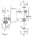
- a prime mover such as an internal combustion engine 1 drives an input shaft 3a of a gearbox/transmission unit 3 via flywheel 2.
- the transmission unit 3 may be configured to adapt gear ratios in a stepped or continuously variable mode to drive first 3b and second 3c output shafts.
- Output shaft 3b drives the vehicle rear axle 4 via rear axle differential 4a.
- the rear axle assembly further comprises rear axle brakes 4b, rear axle final drives 4c, and rear wheels 4d.
- output shaft 3c drives the vehicle front axle 5, with the front axle assembly further comprising differential 5a, brakes 5b, final drive 5c and front wheels 5d.
- ATD all-wheel drive
- a synchronised shift device 7 operable to couple an output shaft 7a thereof with either the input shaft 3a or an output of the transmission in dependence on whether engine speed or groundspeed PTO operation is required. Further details of the construction and operation of shift device 7 are given below with reference to the embodiment of Figures 3 and 4 .
- the synchronised shift device output shaft 7a drives the PTO shaft 10.
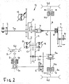
- FIG 2 shows an alternative driveline arrangement having a power split transmission arrangement (indicated generally at 12) in place of the transmission 3 of Figure 1 .
- Planetary or epicyclic gearing 13 separates the torque delivered by the engine 1 for mechanical and hydrostatic branches, with the hydrostatic branch including a pump 14 driven via the planetary gearing 13.
- the pump 14 supplies pressurised fluid to first and second hydrostatic motors 15, 16 (the fluid connection is omitted for reasons of clarity).
- the hydrostatic motors 15, 16 drive an output shaft 20 delivering driving torque to both front 5a and rear 4a axle differentials.
- the synchronised shift device 7 is operable to selectively connect its output shaft 7a to one of the transmission input shaft 3a (for engine speed PTO operation) or transmission output body or shaft 20, via gearing 18, 19 (for ground speed operation).
- the synchronised shift device comprises inner and outer coaxially aligned and respectively rotatable input bodies alternately connectable to the shift device output shaft, with the inner input body connected to the transmission input (engine output) shaft and the outer input body or shaft driveably connected to the transmission output.
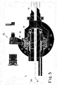
- Figures 3 and 4 show an embodiment of the shift device which comprises a first input shaft 30 axially aligned with, and connectable to (in a manner to be described), an output shaft 32.
- Bearings 34 support an end of the input shaft 30 within a recessed end portion of the output shaft 32 and permit the two shafts to rotate relative to one another and about the common axis A.
- a first annular drive body 36, 38 is coaxially and fixedly mounted on the first input shaft 30 and has a plurality of teeth 40 on a radial outer surface thereof.
- a synchronisation body 42 is rotatably mounted on the first input shaft 30 adjacent the first annular drive body 36, 38.
- a first annular coupling element 44 is rotatably mounted relative to the first annular drive body and driveably engageable therewith through respective friction surfaces 46.
- the coupling element 44 has a plurality of teeth 48 on a radial outer surface thereof.
- a synchronisation sleeve 50 is disposed about the first annular drive body 36, 38, synchronisation body 42 and first annular coupling element 44, the sleeve having teeth on an inner surface thereof and being slidable in an axial direction of the first input shaft from a first disengaged position (as shown), through an intermediate position wherein the teeth of the sleeve engage the teeth 48 of the first annular coupling element 44 and thereby drive engagement of the first annular coupling element and first annular drive body, to an engaged position wherein the teeth of the sleeve engage the teeth 40 of the first annular drive body.
- the second shaft 32 has external gearing 52 over a part of the length thereof, which external gearing remains in driving engagement with gearing 54 on a part of the inner surface of the synchronisation sleeve in all positions of the synchronisation sleeve.
- a control mechanism engages with a recess 58 in the outer surface of the sleeve 50 to control the movement of the sleeve from disengaged to engaged positions.
- the engagement of the friction surfaces between the first annular drive body 36 and first annular coupling element 44 cause the coupling element 44 and sleeve 50 (and thereby also the output shaft 32) to commence rotation at the same speed as the first annular drive body 36 and first input shaft 30 before full engagement by the teeth 40 of the first annular drive body 36 with the sleeve 50.
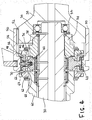
- a third shaft 60 (used here as a second input) coaxially and rotatably disposed about the first shaft 30.
- a second annular drive body 62 is coaxially and fixedly mounted on the third shaft adjacent the synchronisation body 42 and, as for the first annular drive body, it has a plurality of teeth 64 on a radial outer surface thereof.
- a second annular coupling element 66 is rotatably mounted relative to the second annular drive body 62 and is driveably engageable therewith through friction surfaces 68.
- the second annular coupling element 66 has a plurality of teeth 70 on a radial outer surface thereof.
- the synchronisation sleeve 50 is slidable (to the left as it appears in the Figure) through a second intermediate position wherein the teeth of the sleeve engage the teeth 70 of the second annular coupling element 66 and thereby drive engagement of the second annular coupling element 66 and second annular drive body 62 through friction surfaces 68, to a second engaged position wherein the teeth of the sleeve engage the teeth 64 of the second annular drive body.
- the rotation speeds of the third shaft 60 and output shaft 32 are synchronised before the coupling engagement of teeth 64 and sleeve 50.
- the first shaft 30 is connected directly to the engine output/transmission input shaft 3a whilst the third shaft 60 is driveably connected (for example through gearing 18, 19) to the transmission output.
- the unit 7 provides a synchronised shift for the PTO shaft between engine speed and groundspeed operation.
- the synchronised shift unit of Figures 3 and 4 has application beyond switching for PTO drive.
- the shaft 32 may be coupled to a torque source with the shafts 30, 60 providing alternative outputs.
- Figures 5 to 7 show exemplary alternative uses for the shift device.
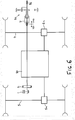
- the device 7 is employed for engaging a crawl speed mode for vehicle operation.
- Engine 1 drives front 5 and rear 4 axles through shift gearbox 80 and via respective differentials 5a, 4a.
- the synchronised shift unit 7 is positioned in the driveline behind the gearbox 80 and is used to switch in or out planetary reduction gear 82 for slow or normal speed operation.
- the device 7 is used for synchronised shifting between two rotation speeds (such as 750 rpm and 540rpm) of an engine speed PTO by switching in or out planetary reduction gear 84 in the line between engine 1 and PTO shaft 86.
- the device is used for synchronised shifting between drive modes in a parallel-hybrid drivetrain.
- the combustion engine 1 provides an input to both shift gearbox 80 and to electrical generator 88.
- the generator 88 through power electronics circuitry 90 and storage battery 92, drives electric motor 94.
- the shift gearbox 80 output provides a first input to the device 7, suitably via inner input shaft 30 ( Fig. 3 ).
- the second input to the device 7, suitably on outer input shaft 60 ( Fig. 3 ), coupled via planetary gearing 96 is from the electric motor 94.
- the shift device 7 thereby enables synchronised shifting between electric E and combustion engine V drive modes with the output from shift device 7 driving front and rear axles 5, 4 via respective differentials 5a, 4a.
- a synchronised shift device for locked connection of at least two shafts, which shafts have different rotation speeds at the start of a shift procedure.
- An arrangement of first annular drive body, synchronisation body and first annular coupling element bring about synchronisation of the shaft speed prior to coupling by a synchronisation sleeve.
- a further shaft, coaxially arranged, may be provided with a similar arrangement of annular drive body and coupling element for synchronised connection with one of the other shafts.
Landscapes
- Engineering & Computer Science (AREA)
- General Engineering & Computer Science (AREA)
- Mechanical Engineering (AREA)
- Chemical & Material Sciences (AREA)
- Combustion & Propulsion (AREA)
- Transportation (AREA)
- Arrangement And Driving Of Transmission Devices (AREA)
- Structure Of Transmissions (AREA)
Claims (13)
- Dispositif de changement de vitesse synchronisé destiné à assurer le couplage verrouillé d'au moins deux arbres de telle sorte que les arbres présentent des vitesses de rotation différentes au début d'une procédure de changement de vitesse, comprenant :a. un premier arbre (30) ;b. un premier corps d'entraînement annulaire (36, 38) monté de manière coaxiale et solidaire sur le premier arbre et comportant une pluralité de dents (40) sur sa surface radiale externe ;c. un corps de synchronisation (42) monté afin de pouvoir tourner sur le premier arbre (30) de manière adjacente au premier corps annulaire (36, 38) ;d. un premier élément de couplage annulaire (44) monté de manière à pouvoir tourner par rapport au premier corps d'entraînement annulaire (36, 38) et pouvant être couplé afin d'assurer l'entraînement à celui-ci, ledit élément de couplage (44) comportant une pluralité de dents (48) sur sa surface externe radiale ;e. un manchon de synchronisation (50) disposé autour du premier corps d'entraînement annulaire (36, 38), du corps de synchronisation (42) et du premier élément de couplage annulaire (44), le manchon comportant des dents (54) sur sa surface interne et pouvant glisser suivant une direction axiale du premier arbre à partir d'une première position découplée, en passant par une position intermédiaire dans laquelle les dents (54) du manchon (50) se couplent aux dents (48) du premier élément de couplage annulaire (44) et assurent ainsi le couplage du premier élément de couplage annulaire (44) et du premier corps d'entraînement annulaire (36, 38), jusqu'à une position couplée dans laquelle les dents (54) du manchon se couplent aux dents (40) du corps d'entraînement (36, 38) ;f. un deuxième arbre (32) comportant un engrenage externe (52) sur une partie de sa longueur, ledit engrenage externe étant couplé de manière à assurer l'entraînement à un engrenage (54) sur une partie de la surface interne du manchon de synchronisation (50) dans toutes les positions du manchon de synchronisation ;g. un troisième arbre (60) disposé de manière coaxiale et afin de pouvoir tourner autour du premier arbre (30) ;h. un second corps d'entraînement annulaire (62) monté de manière coaxiale et solidaire sur le troisième arbre (60), de manière adjacente au corps de synchronisation (42) et comportant une pluralité de dents (64) sur sa surface radiale externe ; eti. un second élément de couplage annulaire (66) monté de manière à pouvoir tourner par rapport au second corps d'entraînement annulaire (62) et pouvant être couplé afin d'assurer un entraînement avec ce dernier, ledit second élément de couplage annulaire comportant une pluralité de dents (70) sur sa surface radiale externe ;dans lequel le manchon de synchronisation (50) peut glisser en passant par une seconde position intermédiaire dans laquelle les dents (54) du manchon se couplent aux dents (70) du second élément de couplage annulaire (66) et assurent ainsi le couplage du second élément de couplage annulaire et du second corps d'entraînement annulaire (62), jusqu'à une seconde position couplée dans laquelle les dents (54) du manchon se couplent aux dents (64) du second corps d'entraînement annulaire.
- Dispositif de changement de vitesse synchronisé selon la revendication 1, dans lequel les premier (30) et deuxième (32) arbres sont alignés axialement.
- Dispositif de changement de vitesse synchronisé selon la revendication 2, dans lequel une partie d'extrémité du premier arbre (30) est reçue de manière à pouvoir tourner (34) dans une partie creuse sur une partie d'extrémité du deuxième arbre (32).
- Dispositif de changement de vitesse synchronisé selon l'une quelconque des revendications 1 à 3, dans lequel le couplage du corps d'entraînement annulaire (36, 62) et de l'élément de couplage annulaire (44, 66) est assuré par l'intermédiaire de surfaces de frottement respectives (46, 68).
- Dispositif de changement de vitesse synchronisé selon l'une quelconque des revendications 1 à 4, dans lequel l'engrenage externe (52) du deuxième arbre (32) comprend une pluralité des cannelures s'étendant axialement sur une partie de la longueur du deuxième arbre.
- Dispositif de transmission comportant un dispositif de changement de vitesse synchronisé (7) selon l'une quelconque des revendications précédentes.
- Dispositif de transmission selon la revendication 6, dans lequel le deuxième arbre (32) est un arbre de sortie (7a) et les premier et troisième arbres (30, 60) sont les arbres d'entrée.
- Dispositif de transmission selon la revendication 7, dans lequel les arbres d'entrée sont couplés à un arbre de transmission (3a) et à un engrenage planétaire (19).
- Dispositif de transmission selon la revendication 8, dans lequel l'engrenage planétaire (19) est entraîné par un moteur électrique (90) et l'arbre de transmission (3a) est entraîné par un moteur thermique (1).
- Dispositif de transmission selon la revendication 6, dans lequel le deuxième arbre (32) est un arbre d'entrée et les premier (30) et troisième (60) arbres sont des arbres de sortie.
- Dispositif de transmission selon la revendication 10, dans lequel les arbres de sortie (30, 60) sont couplés à au moins un essieu moteur ou à un arbre de prise de couple (PTO).
- Dispositif de transmission selon la revendication 10 ou 11, dans lequel les arbres de sortie (30, 60) se sont couplés à un arbre de transmission et à un boîtier de réduction épicycloïdal.
- Dispositif de transmission selon les revendications 8, 9 ou 12, dans lequel l'arbre de transmission est un arbre d'entrée de transmission ou un arbre de sortie de transmission.
Applications Claiming Priority (2)
| Application Number | Priority Date | Filing Date | Title |
|---|---|---|---|
| GBGB1223545.3A GB201223545D0 (en) | 2012-12-21 | 2012-12-21 | Synchronised shift device for a vehicle |
| PCT/EP2013/072983 WO2014095147A1 (fr) | 2012-12-21 | 2013-11-05 | Dispositif de changement de vitesse synchronisé pour un véhicule |
Publications (2)
| Publication Number | Publication Date |
|---|---|
| EP2935925A1 EP2935925A1 (fr) | 2015-10-28 |
| EP2935925B1 true EP2935925B1 (fr) | 2020-01-01 |
Family
ID=47716320
Family Applications (1)
| Application Number | Title | Priority Date | Filing Date |
|---|---|---|---|
| EP13786244.7A Active EP2935925B1 (fr) | 2012-12-21 | 2013-11-05 | Dispositif de changement de vitesse synchronisé pour un véhicule |
Country Status (4)
| Country | Link |
|---|---|
| US (1) | US9441679B2 (fr) |
| EP (1) | EP2935925B1 (fr) |
| GB (1) | GB201223545D0 (fr) |
| WO (1) | WO2014095147A1 (fr) |
Families Citing this family (4)
| Publication number | Priority date | Publication date | Assignee | Title |
|---|---|---|---|---|
| GB201223544D0 (en) * | 2012-12-21 | 2013-02-13 | Agco Int Gmbh | Power take off drive system for a vehicle |
| EP3268639B1 (fr) * | 2015-03-13 | 2020-05-06 | DANA ITALIA S.r.l. | Transmission hydrostatique à entraînement direct |
| US20180154772A1 (en) * | 2015-05-28 | 2018-06-07 | Borgwarner Inc. | Driveline disconnect using multimode clutches |
| CN112026513B (zh) * | 2020-09-07 | 2022-02-15 | 中国第一汽车股份有限公司 | 一种断开装置及同轴电驱动系统 |
Family Cites Families (16)
| Publication number | Priority date | Publication date | Assignee | Title |
|---|---|---|---|---|
| SE417544B (sv) | 1977-11-11 | 1981-03-23 | Saab Scania Ab | Synkroniseringsanordning for vexllada |
| DE3208944A1 (de) * | 1982-03-12 | 1983-09-22 | Zahnradfabrik Friedrichshafen Ag, 7990 Friedrichshafen | Schaltkupplung in zahnraederwechselgetrieben |
| DE3612741A1 (de) | 1986-04-16 | 1987-10-22 | Porsche Ag | Sperrsynchronisiereinrichtung fuer ein zahnraederwechselgetriebe eines kraftfahrzeugs |
| EP0521195B1 (fr) * | 1991-07-04 | 1995-06-07 | CLAAS Kommanditgesellschaft auf Aktien | Transmission hydromécanique à division de puissance |
| US5199704A (en) * | 1991-11-07 | 1993-04-06 | Badami Raymond F | Pool ball positioning apparatus |
| US5311787A (en) * | 1992-06-08 | 1994-05-17 | New Venture Gear, Inc. | Power take-off adaptor |
| US5499951A (en) * | 1993-08-02 | 1996-03-19 | Borg-Warner Automotive, Inc. | Dynamic range shift transfer case with electromagnetic clutch for coupling one output to the input for modulating torque split |
| US7219571B2 (en) * | 2004-11-15 | 2007-05-22 | Borgwarner, Inc. | Transmission having an electro-mechanical gear actuation system |
| JP2008002507A (ja) * | 2006-06-20 | 2008-01-10 | Aisin Ai Co Ltd | 変速機の同期装置 |
| JP4274268B2 (ja) * | 2007-06-19 | 2009-06-03 | トヨタ自動車株式会社 | 動力伝達装置 |
| JP4572956B2 (ja) * | 2008-06-03 | 2010-11-04 | トヨタ自動車株式会社 | 車両の駆動装置 |
| DE102009003107A1 (de) * | 2009-05-14 | 2010-11-18 | Zf Friedrichshafen Ag | Antriebsanordnung für ein Kraftfahrzeug mit einer Nebenabtriebskupplung |
| JP5384376B2 (ja) * | 2010-01-14 | 2014-01-08 | アイシン・エーアイ株式会社 | デュアルクラッチ式自動変速機 |
| DE102010044957A1 (de) | 2010-09-10 | 2012-03-15 | Gm Global Technology Operations, Inc. | Synchronisiervorrichtung eines Wechselschaltgetriebes |
| GB201109100D0 (en) * | 2011-05-27 | 2011-07-13 | Zeroshift Ltd | Transmission system |
| JP5400916B2 (ja) * | 2012-03-19 | 2014-01-29 | 本田技研工業株式会社 | 変速機のシンクロ装置 |
-
2012
- 2012-12-21 GB GBGB1223545.3A patent/GB201223545D0/en not_active Ceased
-
2013
- 2013-11-05 US US14/438,794 patent/US9441679B2/en active Active
- 2013-11-05 EP EP13786244.7A patent/EP2935925B1/fr active Active
- 2013-11-05 WO PCT/EP2013/072983 patent/WO2014095147A1/fr active Application Filing
Non-Patent Citations (1)
| Title |
|---|
| None * |
Also Published As
| Publication number | Publication date |
|---|---|
| US9441679B2 (en) | 2016-09-13 |
| GB201223545D0 (en) | 2013-02-13 |
| EP2935925A1 (fr) | 2015-10-28 |
| WO2014095147A1 (fr) | 2014-06-26 |
| US20150300422A1 (en) | 2015-10-22 |
Similar Documents
| Publication | Publication Date | Title |
|---|---|---|
| EP2934935B1 (fr) | Système d'entraînement de prise de force destiné à un véhicule | |
| US10094457B2 (en) | Electric all-wheel drive two speed with split double reduction planetary | |
| CN106671771B (zh) | 具有双速双级行星齿轮减速器的电动全轮驱动装置 | |
| US9895970B2 (en) | Multi-mode drive system for transaxle applications | |
| US8911321B2 (en) | Tandem axle system | |
| US7951035B2 (en) | Continuously variable torque vectoring axle assembly | |
| US20120115668A1 (en) | Drive arrangement for vehicle auxiliaries | |
| US10415679B2 (en) | Electric all-wheel drive two speed with split double reduction planetary | |
| US20160138695A1 (en) | Disconnecting awd driveline with torque-vectoring capabilities | |
| EP2905510B1 (fr) | Ensemble de transfert de puissance | |
| US20100285913A1 (en) | Transmission With Dual IVT's And Planetary Gear Set | |
| EP2935925B1 (fr) | Dispositif de changement de vitesse synchronisé pour un véhicule | |
| US10520071B2 (en) | Drive unit for shifting a torque balance | |
| US8984973B1 (en) | Multiple speed power take off | |
| GB2493961A (en) | Power takeoff drive system for an agricultural tractor | |
| US9108511B2 (en) | Transfer case | |
| US20210046816A1 (en) | P3 hybrid transfer case | |
| US9958048B2 (en) | Transfer case | |
| US7993230B2 (en) | Dual path hydromechanical powertrain | |
| EP4077013B1 (fr) | Agencement et procédé de transmission destinés un véhicule agricole | |
| EP2142824A1 (fr) | Motopropulseur à quatre roues motrices | |
| EP2730446B1 (fr) | Prise de force à vitesses multiples | |
| US20080173113A1 (en) | Auxiliary transmission for a motor vehicle |
Legal Events
| Date | Code | Title | Description |
|---|---|---|---|
| PUAI | Public reference made under article 153(3) epc to a published international application that has entered the european phase |
Free format text: ORIGINAL CODE: 0009012 |
|
| 17P | Request for examination filed |
Effective date: 20150721 |
|
| AK | Designated contracting states |
Kind code of ref document: A1 Designated state(s): AL AT BE BG CH CY CZ DE DK EE ES FI FR GB GR HR HU IE IS IT LI LT LU LV MC MK MT NL NO PL PT RO RS SE SI SK SM TR |
|
| AX | Request for extension of the european patent |
Extension state: BA ME |
|
| DAX | Request for extension of the european patent (deleted) | ||
| GRAP | Despatch of communication of intention to grant a patent |
Free format text: ORIGINAL CODE: EPIDOSNIGR1 |
|
| STAA | Information on the status of an ep patent application or granted ep patent |
Free format text: STATUS: GRANT OF PATENT IS INTENDED |
|
| INTG | Intention to grant announced |
Effective date: 20190711 |
|
| GRAS | Grant fee paid |
Free format text: ORIGINAL CODE: EPIDOSNIGR3 |
|
| GRAA | (expected) grant |
Free format text: ORIGINAL CODE: 0009210 |
|
| STAA | Information on the status of an ep patent application or granted ep patent |
Free format text: STATUS: THE PATENT HAS BEEN GRANTED |
|
| AK | Designated contracting states |
Kind code of ref document: B1 Designated state(s): AL AT BE BG CH CY CZ DE DK EE ES FI FR GB GR HR HU IE IS IT LI LT LU LV MC MK MT NL NO PL PT RO RS SE SI SK SM TR |
|
| REG | Reference to a national code |
Ref country code: GB Ref legal event code: FG4D |
|
| REG | Reference to a national code |
Ref country code: AT Ref legal event code: REF Ref document number: 1220140 Country of ref document: AT Kind code of ref document: T Effective date: 20200115 Ref country code: CH Ref legal event code: EP |
|
| REG | Reference to a national code |
Ref country code: IE Ref legal event code: FG4D |
|
| REG | Reference to a national code |
Ref country code: DE Ref legal event code: R096 Ref document number: 602013064640 Country of ref document: DE |
|
| REG | Reference to a national code |
Ref country code: NL Ref legal event code: MP Effective date: 20200101 |
|
| REG | Reference to a national code |
Ref country code: LT Ref legal event code: MG4D |
|
| PG25 | Lapsed in a contracting state [announced via postgrant information from national office to epo] |
Ref country code: FI Free format text: LAPSE BECAUSE OF FAILURE TO SUBMIT A TRANSLATION OF THE DESCRIPTION OR TO PAY THE FEE WITHIN THE PRESCRIBED TIME-LIMIT Effective date: 20200101 Ref country code: RS Free format text: LAPSE BECAUSE OF FAILURE TO SUBMIT A TRANSLATION OF THE DESCRIPTION OR TO PAY THE FEE WITHIN THE PRESCRIBED TIME-LIMIT Effective date: 20200101 Ref country code: NL Free format text: LAPSE BECAUSE OF FAILURE TO SUBMIT A TRANSLATION OF THE DESCRIPTION OR TO PAY THE FEE WITHIN THE PRESCRIBED TIME-LIMIT Effective date: 20200101 Ref country code: CZ Free format text: LAPSE BECAUSE OF FAILURE TO SUBMIT A TRANSLATION OF THE DESCRIPTION OR TO PAY THE FEE WITHIN THE PRESCRIBED TIME-LIMIT Effective date: 20200101 Ref country code: PT Free format text: LAPSE BECAUSE OF FAILURE TO SUBMIT A TRANSLATION OF THE DESCRIPTION OR TO PAY THE FEE WITHIN THE PRESCRIBED TIME-LIMIT Effective date: 20200527 Ref country code: LT Free format text: LAPSE BECAUSE OF FAILURE TO SUBMIT A TRANSLATION OF THE DESCRIPTION OR TO PAY THE FEE WITHIN THE PRESCRIBED TIME-LIMIT Effective date: 20200101 Ref country code: NO Free format text: LAPSE BECAUSE OF FAILURE TO SUBMIT A TRANSLATION OF THE DESCRIPTION OR TO PAY THE FEE WITHIN THE PRESCRIBED TIME-LIMIT Effective date: 20200401 |
|
| PG25 | Lapsed in a contracting state [announced via postgrant information from national office to epo] |
Ref country code: IS Free format text: LAPSE BECAUSE OF FAILURE TO SUBMIT A TRANSLATION OF THE DESCRIPTION OR TO PAY THE FEE WITHIN THE PRESCRIBED TIME-LIMIT Effective date: 20200501 Ref country code: SE Free format text: LAPSE BECAUSE OF FAILURE TO SUBMIT A TRANSLATION OF THE DESCRIPTION OR TO PAY THE FEE WITHIN THE PRESCRIBED TIME-LIMIT Effective date: 20200101 Ref country code: GR Free format text: LAPSE BECAUSE OF FAILURE TO SUBMIT A TRANSLATION OF THE DESCRIPTION OR TO PAY THE FEE WITHIN THE PRESCRIBED TIME-LIMIT Effective date: 20200402 Ref country code: LV Free format text: LAPSE BECAUSE OF FAILURE TO SUBMIT A TRANSLATION OF THE DESCRIPTION OR TO PAY THE FEE WITHIN THE PRESCRIBED TIME-LIMIT Effective date: 20200101 Ref country code: BG Free format text: LAPSE BECAUSE OF FAILURE TO SUBMIT A TRANSLATION OF THE DESCRIPTION OR TO PAY THE FEE WITHIN THE PRESCRIBED TIME-LIMIT Effective date: 20200401 Ref country code: HR Free format text: LAPSE BECAUSE OF FAILURE TO SUBMIT A TRANSLATION OF THE DESCRIPTION OR TO PAY THE FEE WITHIN THE PRESCRIBED TIME-LIMIT Effective date: 20200101 |
|
| REG | Reference to a national code |
Ref country code: DE Ref legal event code: R097 Ref document number: 602013064640 Country of ref document: DE |
|
| PG25 | Lapsed in a contracting state [announced via postgrant information from national office to epo] |
Ref country code: SK Free format text: LAPSE BECAUSE OF FAILURE TO SUBMIT A TRANSLATION OF THE DESCRIPTION OR TO PAY THE FEE WITHIN THE PRESCRIBED TIME-LIMIT Effective date: 20200101 Ref country code: ES Free format text: LAPSE BECAUSE OF FAILURE TO SUBMIT A TRANSLATION OF THE DESCRIPTION OR TO PAY THE FEE WITHIN THE PRESCRIBED TIME-LIMIT Effective date: 20200101 Ref country code: DK Free format text: LAPSE BECAUSE OF FAILURE TO SUBMIT A TRANSLATION OF THE DESCRIPTION OR TO PAY THE FEE WITHIN THE PRESCRIBED TIME-LIMIT Effective date: 20200101 Ref country code: EE Free format text: LAPSE BECAUSE OF FAILURE TO SUBMIT A TRANSLATION OF THE DESCRIPTION OR TO PAY THE FEE WITHIN THE PRESCRIBED TIME-LIMIT Effective date: 20200101 Ref country code: SM Free format text: LAPSE BECAUSE OF FAILURE TO SUBMIT A TRANSLATION OF THE DESCRIPTION OR TO PAY THE FEE WITHIN THE PRESCRIBED TIME-LIMIT Effective date: 20200101 Ref country code: RO Free format text: LAPSE BECAUSE OF FAILURE TO SUBMIT A TRANSLATION OF THE DESCRIPTION OR TO PAY THE FEE WITHIN THE PRESCRIBED TIME-LIMIT Effective date: 20200101 |
|
| PLBE | No opposition filed within time limit |
Free format text: ORIGINAL CODE: 0009261 |
|
| STAA | Information on the status of an ep patent application or granted ep patent |
Free format text: STATUS: NO OPPOSITION FILED WITHIN TIME LIMIT |
|
| REG | Reference to a national code |
Ref country code: AT Ref legal event code: MK05 Ref document number: 1220140 Country of ref document: AT Kind code of ref document: T Effective date: 20200101 |
|
| 26N | No opposition filed |
Effective date: 20201002 |
|
| PG25 | Lapsed in a contracting state [announced via postgrant information from national office to epo] |
Ref country code: IT Free format text: LAPSE BECAUSE OF FAILURE TO SUBMIT A TRANSLATION OF THE DESCRIPTION OR TO PAY THE FEE WITHIN THE PRESCRIBED TIME-LIMIT Effective date: 20200101 Ref country code: AT Free format text: LAPSE BECAUSE OF FAILURE TO SUBMIT A TRANSLATION OF THE DESCRIPTION OR TO PAY THE FEE WITHIN THE PRESCRIBED TIME-LIMIT Effective date: 20200101 |
|
| PG25 | Lapsed in a contracting state [announced via postgrant information from national office to epo] |
Ref country code: SI Free format text: LAPSE BECAUSE OF FAILURE TO SUBMIT A TRANSLATION OF THE DESCRIPTION OR TO PAY THE FEE WITHIN THE PRESCRIBED TIME-LIMIT Effective date: 20200101 Ref country code: PL Free format text: LAPSE BECAUSE OF FAILURE TO SUBMIT A TRANSLATION OF THE DESCRIPTION OR TO PAY THE FEE WITHIN THE PRESCRIBED TIME-LIMIT Effective date: 20200101 |
|
| PG25 | Lapsed in a contracting state [announced via postgrant information from national office to epo] |
Ref country code: MC Free format text: LAPSE BECAUSE OF FAILURE TO SUBMIT A TRANSLATION OF THE DESCRIPTION OR TO PAY THE FEE WITHIN THE PRESCRIBED TIME-LIMIT Effective date: 20200101 |
|
| REG | Reference to a national code |
Ref country code: CH Ref legal event code: PL |
|
| PG25 | Lapsed in a contracting state [announced via postgrant information from national office to epo] |
Ref country code: LU Free format text: LAPSE BECAUSE OF NON-PAYMENT OF DUE FEES Effective date: 20201105 |
|
| REG | Reference to a national code |
Ref country code: BE Ref legal event code: MM Effective date: 20201130 |
|
| PG25 | Lapsed in a contracting state [announced via postgrant information from national office to epo] |
Ref country code: CH Free format text: LAPSE BECAUSE OF NON-PAYMENT OF DUE FEES Effective date: 20201130 Ref country code: LI Free format text: LAPSE BECAUSE OF NON-PAYMENT OF DUE FEES Effective date: 20201130 |
|
| PG25 | Lapsed in a contracting state [announced via postgrant information from national office to epo] |
Ref country code: IE Free format text: LAPSE BECAUSE OF NON-PAYMENT OF DUE FEES Effective date: 20201105 |
|
| PG25 | Lapsed in a contracting state [announced via postgrant information from national office to epo] |
Ref country code: TR Free format text: LAPSE BECAUSE OF FAILURE TO SUBMIT A TRANSLATION OF THE DESCRIPTION OR TO PAY THE FEE WITHIN THE PRESCRIBED TIME-LIMIT Effective date: 20200101 Ref country code: MT Free format text: LAPSE BECAUSE OF FAILURE TO SUBMIT A TRANSLATION OF THE DESCRIPTION OR TO PAY THE FEE WITHIN THE PRESCRIBED TIME-LIMIT Effective date: 20200101 Ref country code: CY Free format text: LAPSE BECAUSE OF FAILURE TO SUBMIT A TRANSLATION OF THE DESCRIPTION OR TO PAY THE FEE WITHIN THE PRESCRIBED TIME-LIMIT Effective date: 20200101 |
|
| REG | Reference to a national code |
Ref country code: DE Ref legal event code: R084 Ref document number: 602013064640 Country of ref document: DE |
|
| PG25 | Lapsed in a contracting state [announced via postgrant information from national office to epo] |
Ref country code: MK Free format text: LAPSE BECAUSE OF FAILURE TO SUBMIT A TRANSLATION OF THE DESCRIPTION OR TO PAY THE FEE WITHIN THE PRESCRIBED TIME-LIMIT Effective date: 20200101 Ref country code: AL Free format text: LAPSE BECAUSE OF FAILURE TO SUBMIT A TRANSLATION OF THE DESCRIPTION OR TO PAY THE FEE WITHIN THE PRESCRIBED TIME-LIMIT Effective date: 20200101 |
|
| PG25 | Lapsed in a contracting state [announced via postgrant information from national office to epo] |
Ref country code: BE Free format text: LAPSE BECAUSE OF NON-PAYMENT OF DUE FEES Effective date: 20201130 |
|
| PGFP | Annual fee paid to national office [announced via postgrant information from national office to epo] |
Ref country code: GB Payment date: 20221125 Year of fee payment: 10 |
|
| P01 | Opt-out of the competence of the unified patent court (upc) registered |
Effective date: 20230518 |
|
| PGFP | Annual fee paid to national office [announced via postgrant information from national office to epo] |
Ref country code: FR Payment date: 20231120 Year of fee payment: 11 Ref country code: DE Payment date: 20231121 Year of fee payment: 11 |
|
| GBPC | Gb: european patent ceased through non-payment of renewal fee |
Effective date: 20231105 |