EP2935846B1 - Ratenbasiertes prädiktives modellsteuerungsverfahren zur luftwegregelung eines verbrennungsmotors - Google Patents
Ratenbasiertes prädiktives modellsteuerungsverfahren zur luftwegregelung eines verbrennungsmotors Download PDFInfo
- Publication number
- EP2935846B1 EP2935846B1 EP13821295.6A EP13821295A EP2935846B1 EP 2935846 B1 EP2935846 B1 EP 2935846B1 EP 13821295 A EP13821295 A EP 13821295A EP 2935846 B1 EP2935846 B1 EP 2935846B1
- Authority
- EP
- European Patent Office
- Prior art keywords
- egr
- engine
- controller
- rate
- model
- Prior art date
- Legal status (The legal status is an assumption and is not a legal conclusion. Google has not performed a legal analysis and makes no representation as to the accuracy of the status listed.)
- Active
Links
- 238000000034 method Methods 0.000 title claims description 28
- 238000002485 combustion reaction Methods 0.000 title claims description 8
- 239000000446 fuel Substances 0.000 claims description 18
- PXFBZOLANLWPMH-UHFFFAOYSA-N 16-Epiaffinine Natural products C1C(C2=CC=CC=C2N2)=C2C(=O)CC2C(=CC)CN(C)C1C2CO PXFBZOLANLWPMH-UHFFFAOYSA-N 0.000 claims description 9
- 230000004044 response Effects 0.000 claims description 3
- 230000001419 dependent effect Effects 0.000 claims description 2
- 238000013459 approach Methods 0.000 description 6
- 239000007789 gas Substances 0.000 description 6
- 238000004088 simulation Methods 0.000 description 6
- 238000012545 processing Methods 0.000 description 5
- 238000013461 design Methods 0.000 description 4
- 230000008569 process Effects 0.000 description 4
- 230000003190 augmentative effect Effects 0.000 description 3
- 230000008901 benefit Effects 0.000 description 3
- 238000010586 diagram Methods 0.000 description 3
- 239000011159 matrix material Substances 0.000 description 3
- MWUXSHHQAYIFBG-UHFFFAOYSA-N nitrogen oxide Inorganic materials O=[N] MWUXSHHQAYIFBG-UHFFFAOYSA-N 0.000 description 3
- 230000007704 transition Effects 0.000 description 3
- 230000009471 action Effects 0.000 description 2
- 238000004590 computer program Methods 0.000 description 2
- 230000006399 behavior Effects 0.000 description 1
- 230000008859 change Effects 0.000 description 1
- 239000000567 combustion gas Substances 0.000 description 1
- 238000011217 control strategy Methods 0.000 description 1
- 239000002283 diesel fuel Substances 0.000 description 1
- 230000008030 elimination Effects 0.000 description 1
- 238000003379 elimination reaction Methods 0.000 description 1
- 230000006870 function Effects 0.000 description 1
- 238000005259 measurement Methods 0.000 description 1
- 230000005055 memory storage Effects 0.000 description 1
- 238000005457 optimization Methods 0.000 description 1
- 239000013618 particulate matter Substances 0.000 description 1
- 238000005070 sampling Methods 0.000 description 1
- 238000000638 solvent extraction Methods 0.000 description 1
- 230000000638 stimulation Effects 0.000 description 1
- 230000001052 transient effect Effects 0.000 description 1
Images


Classifications
-
- F—MECHANICAL ENGINEERING; LIGHTING; HEATING; WEAPONS; BLASTING
- F02—COMBUSTION ENGINES; HOT-GAS OR COMBUSTION-PRODUCT ENGINE PLANTS
- F02B—INTERNAL-COMBUSTION PISTON ENGINES; COMBUSTION ENGINES IN GENERAL
- F02B47/00—Methods of operating engines involving adding non-fuel substances or anti-knock agents to combustion air, fuel, or fuel-air mixtures of engines
- F02B47/04—Methods of operating engines involving adding non-fuel substances or anti-knock agents to combustion air, fuel, or fuel-air mixtures of engines the substances being other than water or steam only
- F02B47/08—Methods of operating engines involving adding non-fuel substances or anti-knock agents to combustion air, fuel, or fuel-air mixtures of engines the substances being other than water or steam only the substances including exhaust gas
-
- F—MECHANICAL ENGINEERING; LIGHTING; HEATING; WEAPONS; BLASTING
- F02—COMBUSTION ENGINES; HOT-GAS OR COMBUSTION-PRODUCT ENGINE PLANTS
- F02D—CONTROLLING COMBUSTION ENGINES
- F02D41/00—Electrical control of supply of combustible mixture or its constituents
- F02D41/0025—Controlling engines characterised by use of non-liquid fuels, pluralities of fuels, or non-fuel substances added to the combustible mixtures
- F02D41/0047—Controlling exhaust gas recirculation [EGR]
- F02D41/0077—Control of the EGR valve or actuator, e.g. duty cycle, closed loop control of position
-
- F—MECHANICAL ENGINEERING; LIGHTING; HEATING; WEAPONS; BLASTING
- F02—COMBUSTION ENGINES; HOT-GAS OR COMBUSTION-PRODUCT ENGINE PLANTS
- F02D—CONTROLLING COMBUSTION ENGINES
- F02D41/00—Electrical control of supply of combustible mixture or its constituents
- F02D41/0002—Controlling intake air
- F02D41/0007—Controlling intake air for control of turbo-charged or super-charged engines
-
- F—MECHANICAL ENGINEERING; LIGHTING; HEATING; WEAPONS; BLASTING
- F02—COMBUSTION ENGINES; HOT-GAS OR COMBUSTION-PRODUCT ENGINE PLANTS
- F02D—CONTROLLING COMBUSTION ENGINES
- F02D41/00—Electrical control of supply of combustible mixture or its constituents
- F02D41/0025—Controlling engines characterised by use of non-liquid fuels, pluralities of fuels, or non-fuel substances added to the combustible mixtures
- F02D41/0047—Controlling exhaust gas recirculation [EGR]
- F02D41/005—Controlling exhaust gas recirculation [EGR] according to engine operating conditions
-
- F—MECHANICAL ENGINEERING; LIGHTING; HEATING; WEAPONS; BLASTING
- F02—COMBUSTION ENGINES; HOT-GAS OR COMBUSTION-PRODUCT ENGINE PLANTS
- F02D—CONTROLLING COMBUSTION ENGINES
- F02D41/00—Electrical control of supply of combustible mixture or its constituents
- F02D41/02—Circuit arrangements for generating control signals
- F02D41/14—Introducing closed-loop corrections
- F02D41/1401—Introducing closed-loop corrections characterised by the control or regulation method
- F02D2041/1412—Introducing closed-loop corrections characterised by the control or regulation method using a predictive controller
-
- F—MECHANICAL ENGINEERING; LIGHTING; HEATING; WEAPONS; BLASTING
- F02—COMBUSTION ENGINES; HOT-GAS OR COMBUSTION-PRODUCT ENGINE PLANTS
- F02D—CONTROLLING COMBUSTION ENGINES
- F02D41/00—Electrical control of supply of combustible mixture or its constituents
- F02D41/02—Circuit arrangements for generating control signals
- F02D41/14—Introducing closed-loop corrections
- F02D41/1401—Introducing closed-loop corrections characterised by the control or regulation method
- F02D2041/1413—Controller structures or design
- F02D2041/1415—Controller structures or design using a state feedback or a state space representation
- F02D2041/1416—Observer
-
- F—MECHANICAL ENGINEERING; LIGHTING; HEATING; WEAPONS; BLASTING
- F02—COMBUSTION ENGINES; HOT-GAS OR COMBUSTION-PRODUCT ENGINE PLANTS
- F02D—CONTROLLING COMBUSTION ENGINES
- F02D41/00—Electrical control of supply of combustible mixture or its constituents
- F02D41/02—Circuit arrangements for generating control signals
- F02D41/14—Introducing closed-loop corrections
- F02D41/1401—Introducing closed-loop corrections characterised by the control or regulation method
- F02D2041/1433—Introducing closed-loop corrections characterised by the control or regulation method using a model or simulation of the system
- F02D2041/1434—Inverse model
-
- Y—GENERAL TAGGING OF NEW TECHNOLOGICAL DEVELOPMENTS; GENERAL TAGGING OF CROSS-SECTIONAL TECHNOLOGIES SPANNING OVER SEVERAL SECTIONS OF THE IPC; TECHNICAL SUBJECTS COVERED BY FORMER USPC CROSS-REFERENCE ART COLLECTIONS [XRACs] AND DIGESTS
- Y02—TECHNOLOGIES OR APPLICATIONS FOR MITIGATION OR ADAPTATION AGAINST CLIMATE CHANGE
- Y02T—CLIMATE CHANGE MITIGATION TECHNOLOGIES RELATED TO TRANSPORTATION
- Y02T10/00—Road transport of goods or passengers
- Y02T10/10—Internal combustion engine [ICE] based vehicles
- Y02T10/12—Improving ICE efficiencies
-
- Y—GENERAL TAGGING OF NEW TECHNOLOGICAL DEVELOPMENTS; GENERAL TAGGING OF CROSS-SECTIONAL TECHNOLOGIES SPANNING OVER SEVERAL SECTIONS OF THE IPC; TECHNICAL SUBJECTS COVERED BY FORMER USPC CROSS-REFERENCE ART COLLECTIONS [XRACs] AND DIGESTS
- Y02—TECHNOLOGIES OR APPLICATIONS FOR MITIGATION OR ADAPTATION AGAINST CLIMATE CHANGE
- Y02T—CLIMATE CHANGE MITIGATION TECHNOLOGIES RELATED TO TRANSPORTATION
- Y02T10/00—Road transport of goods or passengers
- Y02T10/10—Internal combustion engine [ICE] based vehicles
- Y02T10/40—Engine management systems
Definitions
- the present description relates, in general, to methods and controls for internal combustion engines and, more particularly, to methods for controlling diesel engines.
- VGT variable geometry turbines
- diesel engines with a VGT In addition to providing optimum performance and fuel economy, modern diesel engines must also meet stringent federal regulations on emissions, particularly, particulate matter and nitrogen oxides. In order to meet all of these requirements, diesel engines with a VGT also use an exhaust gas recirculation (EGR) valve that has a variable controlled position to recirculate varying amounts of engine exhaust gases back into the engine cylinders for more complete combustion and reduced engine emissions.
- EGR exhaust gas recirculation
- one and typically multiple controllers are embedded in the engine control unit (ECU) to control various engine actuators in response to sensors detecting engine performance in order to optimize engine performance, emissions, etc,.
- ECU engine control unit
- MPC Model Predictive Control
- a standard MPC approach incorporates integral type action to guarantee zero state-to-state error that adds additional integral states to the predictive control model.
- the MPC model uses a number of different engine operating ranges (fuel rate and engine speed), and develops a controller for each range to control the engine actuators.
- VGT variable geometry turbine
- EGR throttle EGR throttle
- EGR valve actuator EGR valve actuator
- model predictive controllers to internal combustion engines and, in particular to diesel engines have utilized multiple operating ranges of engine performance, each of which has required a separate predictive controller. Further, each predictive controller uses integral type action that presents problems with overshoot restraints of controlled engine variables.
- model predictive controller for use with an internal combustion engine, which has a minimal number of operating ranges for reduced computation time, and memory storage requirements, while at the same time providing zero state-to-state tracking error of engine controlled performance variables.
- a method for controlling an internal combustion engine having a controller controlling a variable geometry turbine (VGT) and an EGR valve during engine operation includes using a rate based predictive model in the controller responsive to engine intake manifold pressure and EGR valve flow to generate requested EGR flow rate and engine turbine lift.
- VVT variable geometry turbine
- the method further includes defining at least one engine operating zone about a center linearization point for engine speed range and fuel rate ranges.
- the method further includes developing a non-linear model of the engine operating parameters.
- the method further includes developing a linear quadratic model predictive controller in each zone.
- the method further includes linearizing the non-linear model at a center operating point within each operating zone.
- the method further includes developing a second order reduced linear model based on the non-linear model.
- the method further includes generating the rate-based predictive model as a derivative of the linear model.
- the method further includes applying partial inversion to the rate-based predictive model controller outputs to convert an EGR flow control signal to convert the VGT duty cycle signal to a VGT lift control signal.
- the method further includes reducing the number of regions in each of the at least one zone by using a single time instant to enforce overshoot restraint of at least one controller output.
- the method includes estimating the engine state, determining the region of the piecewise affine control law on the estimated engine state, applying feedback gain associated with the selected region of the piecewise affine control law to determine the control rate, and integrating the control rate to determine a control value to be applied to one engine input.
- the method has the controller executing a computer program tangibly embodied on a computer usable medium comprising instructions that when executed by a processor is functional to use a rate based predictive model controller responsive to intake manifold pressure and EGR valve flow rate to control turbine lift and requested EGR flow rate.
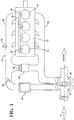
- an internal combustion engine 20 described hereafter by example as a diesel engine, includes an engine block 22 housing a plurality of cylinders 24.
- a fuel rail 26 connected to a fuel supply, not shown, supplies diesel fuel to a plurality of fuel injectors 28 with one fuel injector provided for each cylinder 24.
- An intake manifold 30 is coupled to the cylinders 24 for supplying intake air to each cylinder.
- An intake manifold pressure sensor 32 is coupled to the intake manifold 30 for measuring intake manifold air pressure.
- An exhaust manifold 34 carries combustion gases from the cylinders 24 away from the engine block 22.
- An EGR valve 40 is coupled in a bypass path between the intake manifold 30 and the exhaust manifold 34 to recirculate a portion of the exhaust gases from the exhaust manifold 34 back into the intake manifold 32 for supply to the cylinders 24.
- An EGR cooler 42 may be coupled in the bypass path along with the EGR valve 40.
- An EGR throttle 44 is mounted in the airflow path from the compressor 46 of the variable geometry turbine (VGT) 48 to control gas circulation.
- VGT variable geometry turbine
- An intercooler 50 may be mounted in the intake air path ahead of the EGR throttle 44.
- variable geometry turbine 48 by controlling the angle of the turbine input vanes, controls the intake manifold pressure via the compressor 46.
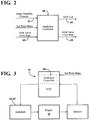
- a rate based predictive model control for the engine 20 uses a plurality of control inputs, such as intake manifold pressure 62 and EGR valve flow rate 64 as shown in Fig. 2 .
- Partial non-linear inversion is used to backtrack the two inputs 62 and 64 to VGT lift duty cycle and EGR valve position, respectively. Partial inversion reduces the degree of model nonlinearity, and is a first step toward reducing the number of zones to cover engine operating range and hence computational complexity.
- Partial inversion also avoids the need to deal with DC gain reversal.
- the controller 60 design uses partitioning of the engine operating range, composed of engine speed and fuel rate, for reduced order linearized engine models within each zone of operation. Only a single zone may be used for good tracking performance under control and state constraints. Thus, the ROM usage in the ECU can be reduced, as well as controller calibration time. A separate controller can be employed for use of the EGR throttle.
- An explicit MPC solution can be computed and is used in the ECU 70, Fig. 3 , rather than one based on on-board quadratic programming. This implementation is motivated by limited computing power and code simplicity.
- the rate based predictive model includes the following elements:
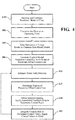
- the nonlinear model for the engine 20 can be developed in step 100, Fig. 4 , using a mean value, gray-box modeling approach that utilized physics and data fits.
- the main dynamic states in the model are the intake manifold pressure, exhaust manifold pressure, pre-throttle pressure, turbocharger turbine speed, EGR cooler outlet temperature, intake manifold density, exhaust manifold density, intake manifold burn gas fraction, exhaust manifold burnt gas fraction, and engine temperature.
- the inputs to the model are engine speed, fuel rate, VGT duty cycle, and EGR throttle position.
- control inputs are chosen to be intake manifold pressure 62 and EGR valve flow rate 64 instead of VGT duty cycle and EGR valve position.
- the control strategy utilizes partial nonlinear inversion to recover VGT duty cycle and EGR valve position from the prescribed control inputs 62 and 64.
- the remaining inputs namely, engine speed, fuel rate and EGR throttle position, remain unchanged.
- the outputs are chosen as VGT lift and EGR valve flow rate, and MAF, not shown. MAF is only used as an input to the Kalman filter.
- the engine operating range (fuel rate and engine speed range) is divided into zones centered at selected operating points.
- the nonlinear model is linearized resulting in a 10 th order linear model.
- Balanced truncation is applied to reduce the model order.
- the order of the linear model can be reduced by two. Since the states of the reduced order model are transformative of physical states, a state observer is used to estimate them from measured outputs. Lowering the order of the linear design and model is advantageous as the controller ROM size is reduced and the state observer is lower dimensional.
- step 102 a 2 nd order continuous time linear model is used.
- the u is the vector of outputs (VGT lift, EGR valve flow), and d is the vector of measured disturbances, (EGR throttle position, engine speed, and fuel rate).
- the model will optimize the control rates u ⁇ k .
- the states u ⁇ k are current values of the controls.
- the d k the derivative of the measured disturbances, is augmented instead 0 ⁇ ⁇ ⁇ 1 is a prediction decay rate on the disturbance derivative and is chosen based on simulations. o k and r k .
- the incremental cost weights tracking error, control effort, and slack variables.
- control horizon was chosen as a single step.
- the explicit MPC rate based controller 60 is generated in step 106 in the form of a piecewise affine control law using a MPT toolbox for Matlab.
- the controller 60 has a piecewise affine control law form.
- the total augmented state, X aug , in (12) is of dimension 16.
- Partial inversion is applied in the rate based predictive model controller 60 to replace EGR valve position control signal by EGR flow control signal and to replace VGT duty cycle signal by VGT lift control signal.
- the EGR valve flow is a function of intake pressure, exhaust pressure, exhaust temperature, EGR valve position, and engine speed.
- the inversion of EGR flow to EGR valve position is described in Huang et al. [2013]. Because EGR valve flow available as an ECU estimate, a PID controller can also be applied to the difference between EGR flow estimate and the requested EGR flow. Figure 5 suggests that even without the PID controller, the inversion is sufficiently accurate. The discrepancies are compensated by the PID feedback and the by the outer loop MPC feedback.
- the partial inversion (but without dynamic compensation since VGT lift is not measured) is also used to convert VGT life requested by the MPC controller to a commanded VGT duty cycle.
- the pneumatic VGT actuator dynamics are complicated and involve hysteresis. Nevertheless, the model translates VGT lift, engine speed, exhaust pressure and exhaust temperature (that are available as ECU estimates) into VGT duty cycle, see Figure 6 .
- the throttle controller sets the throttle position to the engine speed and fuel-dependent set-point, ⁇ req , prescribed by the throttle position feed-forward map, provided a margin, M egr , is maintained between the requested EGR flow. W egr req . If this margin is eroded, a PID controller, C PID(8) , is applied to recover the margin by closing the EGR throttle.
- n r is the number of regions per zone.
- Table 1 n z ⁇ n r [kB] flops [ ⁇ s] RB-MPC w/6 i.c. 1 28 141.3 6551 406.2 RB-MPC w /1 i.c. 1 10 35.0 1615 100.0
- regions that have a small Chebyshey radius can be removed.
- region elimination the selected region is given by i ⁇ argmin i max j H ij x aug ⁇ K ij ) where j corresponds to j th inequality in the definition of the i th region to which x aug strictly belongs is found. For strategies that use intermittent constraint enforcement, around half of the region have been additional removed.
- the number of regions depends on the number of possible combinations of active constraints. Hence, to reduce the number of regions, the approach of enforcing the constraints at all-time instants over the prediction horizon is modified by enforcing tightened constraints at a smaller number of time instants.
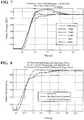
- the final design of RB-MPC 60 uses just a single time instant (20 steps ahead) to enforce the intake pressure overshoot constraint.
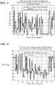
- Figure 7 demonstrates this approach with RB-MPC controller 60.
- this approach is able to handle the overshoot constraint during a large step in fueling rate from 5 to 55 mm 3 /stroke which corresponds to a 124 kPa to 232 kPa step in the intake pressure set-point.
- the transient behavior highlights the benefits of using a rate-based approach.
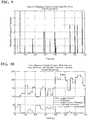
- the Markov Chain process is intended to speed up the average case region selection process by searching for the region x aug is currently inside in likelihood order. From drive cycle stimulations and the trajectory of regions visited, a transition probability matrix for an associated Markov Chain model of region transitions is created. Each entry represents the probability of transitioning from the previous region, indexed by column. The probability transition matrix is then sorted to produce, for each previous region, the order in which to check for the current region. Figure 8 shows the number of regions checked during this simulation. In the worst case, the computation time is the same as the one shown in Table 1.
- RB-MPC controller 60 The simulation results of RB-MPC controller 60 on the nonlinear model of the engine 20 as shown in Figures 10-13 . These figures show fuel step responses covering engine speed ranges from 1000 to 4000 rpm and fuel rates between 5 and 55 mm 3 stroke. Every 100sec is a step up of engine speed by 500 rpm. A single RB-MPC controller 60 is used and the linearization point is located at 1750 rpm, 45 mm3/stroke. The controller demonstrates good tracking performances and overshoots constraint handling through the entire operating range. As apparent from Figure 11 , the EGR throttle occasionally closes, e.g. at 25 sec, more than dictated by EGR throttle set-point to recover EGR flow margin.
- the controller 60 is implemented in the ECU 70 of the engine 20 as shown in Fig. 3 .
- the ECU 70 has a processor that executes a computer program tangibly embodied on computer useable medium and comprising instructions that when executed by the processor implement the rate based predictive model controller described above.
- the ECU 70 may include a central processing unit which may any type of device, or multiple devices, capable of manipulating or processing information.
- the central processing unit is practiced with a single processor or multiple processors.
- the central processing unit accesses a memory, which can be a random access memory or any other suitable type of storage device.
- the memory can include code and data that is accessed by the central processing unit.
- the memory can further include an operating system and application programs, including the rate based predictive model controller used to performed the method described herein.
- the ECU 70 using the rate based predictive model controller 60 will estimate the engine state space that is divided into regions by means of an algorithm or formulas. Once the state is determined in state 110, the ECU 70, via the rate based predictive model controller 60, determines, by using the estimated state in step 108, the region of a piecewise affine control law generated in step 112.
- the ECU 70 via the rate based predictive model controller 60, in step 114, applies a feedback gain, stored in memory, which is associated with the selected region to determine the control rates of the actuator 62, 64.
- the ECU 70 via the rate based predictive model controller 60, in step 116, integrates the determined control rate from step 114 to determine a control value for the actuator 62 or 64, which is then applied by the ECU 60 to the actuator the outputs 62 or 64.
Landscapes
- Engineering & Computer Science (AREA)
- Chemical & Material Sciences (AREA)
- Combustion & Propulsion (AREA)
- Mechanical Engineering (AREA)
- General Engineering & Computer Science (AREA)
- Combined Controls Of Internal Combustion Engines (AREA)
- Feedback Control In General (AREA)
- Output Control And Ontrol Of Special Type Engine (AREA)
- Supercharger (AREA)
- Exhaust-Gas Circulating Devices (AREA)
Claims (3)
- Verfahren zum Steuern einer Verbrennungskraftmaschine mit einen Controller, der eine Turbine mit variabler Geometrie und ein AGR-Ventil während eines Betriebs der Maschine steuert, wobei das Verfahren aufweist:Entwickeln eines nichtlinearen Modells unter Verwendung von Maschinenbetriebsparametern;Definieren zumindest einer Maschinenbetriebszone um einen Zentrallinearisierungspunkt für Maschinendrehzahlbereiche und Kraftstoffverbrauchsbereiche;Linearisieren des nichtlinearen Modells an einem Zentrallinearisierungspunkt innerhalb einer Maschinenbetriebszone;Entwickeln eines reduzierten Linearmodells zweiter Ordnung auf Basis des nichtlinearen Modells;Entwickeln einer Linearquadratmodell-Prädiktivsteuerung für jede Maschinenbetriebszone auf Basis des nichtlinearen Modells;Erzeugen eines ratenbasierten Prädiktivmodells als ein Derivat des Linearmodells; Erzeugen des Linearmodells als ein Linearquadratmodell in der Form einer stückweisen affinen Steuerregel, wobei:wobei i ∈ {1,...,nr} den i-ten polyhedralen Bereich bezeichnet, (F ixaug +G i ) die angefragten Steuerraten gibt, u̇, u den Vektor von Ausgaben bezeichnet, d den Vektor von Störungen bezeichnet, und

 Schätzen eines Maschinenzustands;Bestimmen eines Bereichs der stückweisen affinen Steuerregel auf Basis des geschätzten Maschinenzustands;Anwenden einer Feedback-Verstärkung, diedem ausgewählten Bereich der stückweisen affinen Steuerregel zugeordnet ist, um eine Steuerrate zu bestimmen; undIntegrieren der Steuerrate, um einen Steuerwert zu bestimmen, der auf eine Maschineneingabe angewendet wird,unter Verwendung des ratenbasieren Prädiktivmodells in dem Controller, ansprechend auf einen Maschinenansaugkrümmerdruck und eine AGR-Ventilströmungsrate, um den angefragten Maschinenturbinenhub und die angefragte AGR-Strömungsrate zu erzeugen; undSteuern, durch den Controller, einer Turbine mit variabler Geometrie und eines AGR-Ventils während des Betriebs der Maschine als Reaktion auf den Ansaugkrümmerdruck und die angefragte AGR-Ventilströmungsrate, um einen Turbinenhub und eine AGR-Strömungsrate zu erzeugen.
 - Verfahren nach Anspruch 1, ferner aufweisend:
Anwenden einer partiellen Inversion auf die ratenbasierte Prädiktivmodellsteuerung, um ein AGR-Ventilströmungsratensignal zu einem AGR-Ventilpositionstastverhältnissignal zu konvertieren und um ein Turbinenhubsignal zu einem Turbinenhubtastverhältnissignal zu konvertieren. - Verfahren nach Anspruch 1, ferner aufweisend:
Entwickeln einer AGR-Drosselsteuerung gemäß:
Voraussetzung, dass zwischen der angefragten AGR-Strömung,
Applications Claiming Priority (2)
| Application Number | Priority Date | Filing Date | Title |
|---|---|---|---|
| US13/724,957 US9581080B2 (en) | 2012-12-21 | 2012-12-21 | Rate-based model predictive control method for internal combustion engine air path control |
| PCT/US2013/076391 WO2014100334A1 (en) | 2012-12-21 | 2013-12-19 | Rate-based model predictive control method for internal combustion engine air path control |
Publications (2)
| Publication Number | Publication Date |
|---|---|
| EP2935846A1 EP2935846A1 (de) | 2015-10-28 |
| EP2935846B1 true EP2935846B1 (de) | 2021-12-01 |
Family
ID=49956411
Family Applications (1)
| Application Number | Title | Priority Date | Filing Date |
|---|---|---|---|
| EP13821295.6A Active EP2935846B1 (de) | 2012-12-21 | 2013-12-19 | Ratenbasiertes prädiktives modellsteuerungsverfahren zur luftwegregelung eines verbrennungsmotors |
Country Status (5)
| Country | Link |
|---|---|
| US (1) | US9581080B2 (de) |
| EP (1) | EP2935846B1 (de) |
| JP (1) | JP6416781B2 (de) |
| CN (1) | CN105308296B (de) |
| WO (1) | WO2014100334A1 (de) |
Families Citing this family (48)
| Publication number | Priority date | Publication date | Assignee | Title |
|---|---|---|---|---|
| US9222426B2 (en) * | 2012-02-17 | 2015-12-29 | Ford Global Technologies, Llc | Transient air flow control |
| US9534547B2 (en) | 2012-09-13 | 2017-01-03 | GM Global Technology Operations LLC | Airflow control systems and methods |
| US9382865B2 (en) | 2014-03-26 | 2016-07-05 | GM Global Technology Operations LLC | Diagnostic systems and methods using model predictive control |
| US9347381B2 (en) | 2014-03-26 | 2016-05-24 | GM Global Technology Operations LLC | Model predictive control systems and methods for internal combustion engines |
| US9599049B2 (en) | 2014-06-19 | 2017-03-21 | GM Global Technology Operations LLC | Engine speed control systems and methods |
| US9784198B2 (en) | 2015-02-12 | 2017-10-10 | GM Global Technology Operations LLC | Model predictive control systems and methods for increasing computational efficiency |
| US9863345B2 (en) | 2012-11-27 | 2018-01-09 | GM Global Technology Operations LLC | System and method for adjusting weighting values assigned to errors in target actuator values of an engine when controlling the engine using model predictive control |
| US9797318B2 (en) | 2013-08-02 | 2017-10-24 | GM Global Technology Operations LLC | Calibration systems and methods for model predictive controllers |
| US9587573B2 (en) | 2014-03-26 | 2017-03-07 | GM Global Technology Operations LLC | Catalyst light off transitions in a gasoline engine using model predictive control |
| US9376965B2 (en) * | 2013-04-23 | 2016-06-28 | GM Global Technology Operations LLC | Airflow control systems and methods using model predictive control |
| US9605615B2 (en) | 2015-02-12 | 2017-03-28 | GM Global Technology Operations LLC | Model Predictive control systems and methods for increasing computational efficiency |
| US9920697B2 (en) | 2014-03-26 | 2018-03-20 | GM Global Technology Operations LLC | Engine control systems and methods for future torque request increases |
| US9732688B2 (en) | 2014-03-26 | 2017-08-15 | GM Global Technology Operations LLC | System and method for increasing the temperature of a catalyst when an engine is started using model predictive control |
| US9528453B2 (en) | 2014-11-07 | 2016-12-27 | GM Global Technologies Operations LLC | Throttle control systems and methods based on pressure ratio |
| US9541019B2 (en) | 2014-03-26 | 2017-01-10 | GM Global Technology Operations LLC | Estimation systems and methods with model predictive control |
| US9765703B2 (en) | 2013-04-23 | 2017-09-19 | GM Global Technology Operations LLC | Airflow control systems and methods using model predictive control |
| US9429085B2 (en) | 2013-04-23 | 2016-08-30 | GM Global Technology Operations LLC | Airflow control systems and methods using model predictive control |
| US9714616B2 (en) | 2014-03-26 | 2017-07-25 | GM Global Technology Operations LLC | Non-model predictive control to model predictive control transitions |
| US9435274B2 (en) | 2014-03-26 | 2016-09-06 | GM Global Technology Operations LLC | System and method for managing the period of a control loop for controlling an engine using model predictive control |
| US9562484B2 (en) * | 2012-12-21 | 2017-02-07 | Toyota Motor Engineering & Manufacturing North America, Inc. | Rate-based contractive model predictive control method for internal combustion engine air path control |
| US9989001B2 (en) * | 2012-12-21 | 2018-06-05 | Toyota Motor Engineering & Manufacturing North America, Inc. | Discrete time rate-based model predictive control method for internal combustion engine air path control |
| EP2972604B1 (de) | 2013-03-15 | 2020-04-29 | United Technologies Corporation | Auf einem kompakten luft-wärme-modell basierender startalgorithmus für ein regelungssystem |
| JP6156429B2 (ja) * | 2014-05-26 | 2017-07-05 | トヨタ自動車株式会社 | 内燃機関の制御装置 |
| US9951701B2 (en) | 2014-09-22 | 2018-04-24 | General Electric Company | Method and systems for EGR control |
| EP3091212A1 (de) * | 2015-05-06 | 2016-11-09 | Honeywell International Inc. | Identifikationsansatz für verbrennungsmotor-mittelwertmodelle |
| CN104915472B (zh) * | 2015-05-13 | 2018-08-24 | 北京宝沃汽车有限公司 | 发动机冷却系统优化仿真计算方法 |
| DE102016121338B4 (de) * | 2015-11-23 | 2020-06-18 | The Regents Of The University Of Michigan | System und Verfahren zum Steuern einer Brennkraftmaschine sowie nichtflüchtiges Speichermedium |
| CN105888861B (zh) * | 2016-04-08 | 2018-10-16 | 潍柴动力股份有限公司 | 一种egr与vtg的控制方法及系统 |
| DK201770423A1 (en) | 2016-06-11 | 2018-01-15 | Apple Inc | Activity and workout updates |
| US9938908B2 (en) | 2016-06-14 | 2018-04-10 | GM Global Technology Operations LLC | System and method for predicting a pedal position based on driver behavior and controlling one or more engine actuators based on the predicted pedal position |
| US10190522B2 (en) * | 2016-06-17 | 2019-01-29 | Toyota Motor Engineering & Manufacturing North America, Inc. | Hybrid partial and full step quadratic solver for model predictive control of diesel engine air path flow and methods of use |
| JP2018048721A (ja) * | 2016-09-23 | 2018-03-29 | 株式会社デンソーテン | 制御装置および制御方法 |
| US10309059B2 (en) * | 2016-09-23 | 2019-06-04 | Honeywell International Inc. | Method of designing model predictive control for cross directional flat sheet manufacturing processes to guarantee temporal robust stability and performance |
| JP6150934B1 (ja) | 2016-10-17 | 2017-06-21 | 三菱重工業株式会社 | 情報処理方法、情報処理装置、プログラム、及び情報処理システム |
| US11454188B2 (en) | 2017-06-02 | 2022-09-27 | The Mathworks, Inc. | Systems and methods for rescaling executable simulation models |
| US12056425B2 (en) | 2017-06-02 | 2024-08-06 | The Mathworks, Inc. | Systems and methods for rescaling executable simulation models |
| US10316784B2 (en) * | 2017-06-06 | 2019-06-11 | Gm Global Technology Operations Llc. | Air charging control of engine assembly with multiple turbines |
| US10156197B1 (en) * | 2017-06-16 | 2018-12-18 | GM Global Technology Operations LLC | Model predictive control systems and methods for increasing computational efficiency |
| DE102017009583B3 (de) * | 2017-10-16 | 2018-11-22 | Mtu Friedrichshafen Gmbh | Verfahren zur modellbasierten Steuerung und Regelung einer Brennkraftmaschine |
| US10844795B2 (en) * | 2018-01-10 | 2020-11-24 | Toyota Motor Engineering & Manufacturing North America, Inc. | Feedforward and feedback architecture for air path model predictive control of an internal combustion engine |
| CN108365986B (zh) * | 2018-02-07 | 2019-06-21 | 重庆大学 | 基于模型预测控制的混合动力车队协同能量管理方法 |
| DE102018213177B4 (de) * | 2018-08-07 | 2023-02-09 | Volkswagen Aktiengesellschaft | Verfahren zur Leistungsregelung des Verbrennungsmotors eines Kraftfahrzeugs |
| KR20200066751A (ko) | 2018-11-30 | 2020-06-11 | 현대자동차주식회사 | 차량의 엔진 제어방법 |
| DK201970532A1 (en) | 2019-05-06 | 2021-05-03 | Apple Inc | Activity trends and workouts |
| CN110716431B (zh) * | 2019-09-30 | 2022-03-29 | 哈尔滨工程大学 | 一种基于观测器的增压柴油机气路抗干扰容错控制方法 |
| FR3112167B1 (fr) | 2020-07-06 | 2022-07-15 | Renault Sas | Système de contrôle et de commande d'un moteur à combustion interne de type Diesel de véhicule automobile |
| CN112327669B (zh) * | 2020-11-14 | 2022-02-18 | 大连理工大学 | 一种航空发动机显式预测控制器的设计方法 |
| US11761392B2 (en) | 2021-05-17 | 2023-09-19 | Caterpillar Inc. | Method and system for engine air system control |
Citations (7)
| Publication number | Priority date | Publication date | Assignee | Title |
|---|---|---|---|---|
| FR2764941A1 (fr) * | 1997-06-19 | 1998-12-24 | Renault | Procede et dispositif de controle d'un moteur a combustion interne, a allumage commande |
| US20050131620A1 (en) * | 2002-01-31 | 2005-06-16 | Cambridge Consultants Limited | Control system |
| US20060137347A1 (en) * | 2004-12-29 | 2006-06-29 | Stewart Gregory E | Coordinated multivariable control of fuel and air in engines |
| US20090222245A1 (en) * | 2008-02-29 | 2009-09-03 | Ono Sokki Co., Ltd. | Method, computer, and recording medium storing a program for computing engine design variables |
| US20100268353A1 (en) * | 2007-12-21 | 2010-10-21 | Crisalle Oscar D | Systems and Methods for Offset-Free Model Predictive Control |
| JP2010249057A (ja) * | 2009-04-16 | 2010-11-04 | Isuzu Motors Ltd | 内燃機関の制御方法及び制御装置 |
| US20110301723A1 (en) * | 2010-06-02 | 2011-12-08 | Honeywell International Inc. | Using model predictive control to optimize variable trajectories and system control |
Family Cites Families (18)
| Publication number | Priority date | Publication date | Assignee | Title |
|---|---|---|---|---|
| US5527238A (en) | 1995-04-10 | 1996-06-18 | Ford Motor Company | Automatic transmission bypass clutch slip control using nonlinear nverse dynamics |
| US5771482A (en) | 1995-12-15 | 1998-06-23 | The Ohio State University | Estimation of instantaneous indicated torque in multicylinder engines |
| DE10034789B4 (de) * | 2000-07-18 | 2014-06-05 | Robert Bosch Gmbh | Verfahren und Vorrichtung zur Kompensation des nichtlinearen Verhaltens des Luftsystems einer Brennkraftmaschine |
| US7076953B2 (en) * | 2002-09-19 | 2006-07-18 | Detroit Diesel Corporation | Method for controlling an engine with VGT and EGR systems |
| US6990401B2 (en) | 2002-10-04 | 2006-01-24 | Daimlerchrysler Ag | Predictive speed control for a motor vehicle |
| US7328577B2 (en) * | 2004-12-29 | 2008-02-12 | Honeywell International Inc. | Multivariable control for an engine |
| WO2006104434A1 (en) | 2005-04-01 | 2006-10-05 | Hoerbiger Kompressortechnik Holding Gmbh | Method for the estimation of combustion parameters |
| JP2007113563A (ja) * | 2005-09-26 | 2007-05-10 | Honda Motor Co Ltd | 内燃機関の制御装置 |
| DE102005060350B4 (de) * | 2005-12-16 | 2014-07-10 | Continental Automotive Gmbh | Verfahren zur Regelung eines Verbrennungsprozesses einer aufgeladenen Brennkraftmaschine mit Abgasrückführung |
| US7415389B2 (en) | 2005-12-29 | 2008-08-19 | Honeywell International Inc. | Calibration of engine control systems |
| CA2664172C (en) | 2006-09-16 | 2016-03-29 | Terence Gilhuly | Improved sensors and sensing for monitoring neuromuscular blockade |
| US7908858B2 (en) * | 2007-07-31 | 2011-03-22 | Caterpillar Inc. | System that limits turbo speed by controlling fueling |
| US8090456B2 (en) | 2008-11-03 | 2012-01-03 | United Technologies Corporation | System and method for design and control of engineering systems utilizing component-level dynamic mathematical model |
| US8397499B2 (en) * | 2009-08-24 | 2013-03-19 | Ford Global Technologies, Llc | Methods and systems for turbocharger control |
| US20110264353A1 (en) * | 2010-04-22 | 2011-10-27 | Atkinson Christopher M | Model-based optimized engine control |
| US8439021B2 (en) * | 2010-06-15 | 2013-05-14 | Deere & Company | EGR system for an internal combustion engine |
| JP5569426B2 (ja) * | 2011-02-16 | 2014-08-13 | 富士通株式会社 | エンジン制御プログラム及び装置 |
| US9765703B2 (en) * | 2013-04-23 | 2017-09-19 | GM Global Technology Operations LLC | Airflow control systems and methods using model predictive control |
-
2012
- 2012-12-21 US US13/724,957 patent/US9581080B2/en not_active Expired - Fee Related
-
2013
- 2013-12-19 CN CN201380067640.8A patent/CN105308296B/zh not_active Expired - Fee Related
- 2013-12-19 JP JP2015549673A patent/JP6416781B2/ja not_active Expired - Fee Related
- 2013-12-19 WO PCT/US2013/076391 patent/WO2014100334A1/en active Application Filing
- 2013-12-19 EP EP13821295.6A patent/EP2935846B1/de active Active
Patent Citations (7)
| Publication number | Priority date | Publication date | Assignee | Title |
|---|---|---|---|---|
| FR2764941A1 (fr) * | 1997-06-19 | 1998-12-24 | Renault | Procede et dispositif de controle d'un moteur a combustion interne, a allumage commande |
| US20050131620A1 (en) * | 2002-01-31 | 2005-06-16 | Cambridge Consultants Limited | Control system |
| US20060137347A1 (en) * | 2004-12-29 | 2006-06-29 | Stewart Gregory E | Coordinated multivariable control of fuel and air in engines |
| US20100268353A1 (en) * | 2007-12-21 | 2010-10-21 | Crisalle Oscar D | Systems and Methods for Offset-Free Model Predictive Control |
| US20090222245A1 (en) * | 2008-02-29 | 2009-09-03 | Ono Sokki Co., Ltd. | Method, computer, and recording medium storing a program for computing engine design variables |
| JP2010249057A (ja) * | 2009-04-16 | 2010-11-04 | Isuzu Motors Ltd | 内燃機関の制御方法及び制御装置 |
| US20110301723A1 (en) * | 2010-06-02 | 2011-12-08 | Honeywell International Inc. | Using model predictive control to optimize variable trajectories and system control |
Non-Patent Citations (1)
| Title |
|---|
| JONATHAN A DECASTRO: "Rate-Based Model Predictive Control of Turbofan Engine Clearance", JOURNAL OF PROPULSION AND POWER, vol. 23, no. 4, 1 July 2007 (2007-07-01), pages 804 - 813, XP055423424, Retrieved from the Internet <URL:https://ntrs.nasa.gov/archive/nasa/casi.ntrs.nasa.gov/20060056313.pdf> [retrieved on 20171115], DOI: 10.2514/1.25846 * |
Also Published As
| Publication number | Publication date |
|---|---|
| JP2016507691A (ja) | 2016-03-10 |
| US9581080B2 (en) | 2017-02-28 |
| JP6416781B2 (ja) | 2018-10-31 |
| CN105308296A (zh) | 2016-02-03 |
| US20140174413A1 (en) | 2014-06-26 |
| CN105308296B (zh) | 2018-11-30 |
| EP2935846A1 (de) | 2015-10-28 |
| WO2014100334A1 (en) | 2014-06-26 |
Similar Documents
| Publication | Publication Date | Title |
|---|---|---|
| EP2935846B1 (de) | Ratenbasiertes prädiktives modellsteuerungsverfahren zur luftwegregelung eines verbrennungsmotors | |
| US9562484B2 (en) | Rate-based contractive model predictive control method for internal combustion engine air path control | |
| US9989001B2 (en) | Discrete time rate-based model predictive control method for internal combustion engine air path control | |
| EP1864012B1 (de) | Koordinierte multivariable kraftstoff- und luftkontrolle bei motoren | |
| Stefanopoulou et al. | Control of variable geometry turbocharged diesel engines for reduced emissions | |
| Zhao et al. | An explicit model predictive control framework for turbocharged diesel engines | |
| US9765621B2 (en) | Switch gain scheduled explicit model predictive control of diesel engines | |
| CN106762170B (zh) | 用于内燃机空气路径控制的基于离散时间速率的模型预测控制方法 | |
| Wang et al. | Quantitative feedback design of air and boost pressure control system for turbocharged diesel engines | |
| US9732684B2 (en) | Control apparatus | |
| US10422290B1 (en) | Supervisory model predictive controller for diesel engine emissions control | |
| US20190085780A1 (en) | Smoothed and regularized fischer-burmeister solver for embedded real-time constrained optimal control problems in automotive systems | |
| Huang et al. | Towards combining nonlinear and predictive control of diesel engines | |
| Huang et al. | Rate-based model predictive control of diesel engines | |
| Liao-McPherson et al. | A cascaded economic model predictive control strategy for a diesel engine using a non-uniform prediction horizon discretization | |
| Zhao et al. | Explicit model predictive control on the air path of turbocharged diesel engines | |
| US10844795B2 (en) | Feedforward and feedback architecture for air path model predictive control of an internal combustion engine | |
| Huang | Low Complexity Model Predictive Control of a Diesel Engine Airpath. | |
| Shutty et al. | 12 Air System Control for Advanced Diesel Engines | |
| Ejiri et al. | Transient control of air intake system in diesel engines | |
| Min et al. | Iterative learning control algorithm for feedforward controller of EGR and VGT systems in a CRDI diesel engine | |
| Park et al. | Gain-scheduled EGR control algorithm for light-duty diesel engines with static-gain parameter modeling | |
| Zhang et al. | Modeling and Control of Diesel Engine Emissions using Multi-layer Neural Networks and Economic Model Predictive Control | |
| Shirai et al. | An application of a model-prediction-based reference modification algorithm to engine air path control | |
| Keller | Two-stage model predictive control for the air path of a turbocharged gasoline engine with exhaust gas recirculation |
Legal Events
| Date | Code | Title | Description |
|---|---|---|---|
| PUAI | Public reference made under article 153(3) epc to a published international application that has entered the european phase |
Free format text: ORIGINAL CODE: 0009012 |
|
| 17P | Request for examination filed |
Effective date: 20150717 |
|
| AK | Designated contracting states |
Kind code of ref document: A1 Designated state(s): AL AT BE BG CH CY CZ DE DK EE ES FI FR GB GR HR HU IE IS IT LI LT LU LV MC MK MT NL NO PL PT RO RS SE SI SK SM TR |
|
| AX | Request for extension of the european patent |
Extension state: BA ME |
|
| DAX | Request for extension of the european patent (deleted) | ||
| STAA | Information on the status of an ep patent application or granted ep patent |
Free format text: STATUS: EXAMINATION IS IN PROGRESS |
|
| 17Q | First examination report despatched |
Effective date: 20171122 |
|
| RAP1 | Party data changed (applicant data changed or rights of an application transferred) |
Owner name: THE REGENTS OF THE UNIVERSITY OF MICHIGAN Owner name: TOYOTA MOTOR ENGINEERING & MANUFACTURING NORTH AME |
|
| STAA | Information on the status of an ep patent application or granted ep patent |
Free format text: STATUS: EXAMINATION IS IN PROGRESS |
|
| GRAP | Despatch of communication of intention to grant a patent |
Free format text: ORIGINAL CODE: EPIDOSNIGR1 |
|
| STAA | Information on the status of an ep patent application or granted ep patent |
Free format text: STATUS: GRANT OF PATENT IS INTENDED |
|
| RIC1 | Information provided on ipc code assigned before grant |
Ipc: F02D 41/14 20060101AFI20210521BHEP Ipc: F02D 41/00 20060101ALI20210521BHEP |
|
| INTG | Intention to grant announced |
Effective date: 20210616 |
|
| GRAS | Grant fee paid |
Free format text: ORIGINAL CODE: EPIDOSNIGR3 |
|
| GRAA | (expected) grant |
Free format text: ORIGINAL CODE: 0009210 |
|
| STAA | Information on the status of an ep patent application or granted ep patent |
Free format text: STATUS: THE PATENT HAS BEEN GRANTED |
|
| AK | Designated contracting states |
Kind code of ref document: B1 Designated state(s): AL AT BE BG CH CY CZ DE DK EE ES FI FR GB GR HR HU IE IS IT LI LT LU LV MC MK MT NL NO PL PT RO RS SE SI SK SM TR |
|
| REG | Reference to a national code |
Ref country code: GB Ref legal event code: FG4D |
|
| REG | Reference to a national code |
Ref country code: AT Ref legal event code: REF Ref document number: 1451975 Country of ref document: AT Kind code of ref document: T Effective date: 20211215 Ref country code: CH Ref legal event code: EP |
|
| REG | Reference to a national code |
Ref country code: IE Ref legal event code: FG4D |
|
| REG | Reference to a national code |
Ref country code: DE Ref legal event code: R096 Ref document number: 602013080282 Country of ref document: DE |
|
| REG | Reference to a national code |
Ref country code: LT Ref legal event code: MG9D |
|
| REG | Reference to a national code |
Ref country code: NL Ref legal event code: MP Effective date: 20211201 |
|
| REG | Reference to a national code |
Ref country code: AT Ref legal event code: MK05 Ref document number: 1451975 Country of ref document: AT Kind code of ref document: T Effective date: 20211201 |
|
| PG25 | Lapsed in a contracting state [announced via postgrant information from national office to epo] |
Ref country code: RS Free format text: LAPSE BECAUSE OF FAILURE TO SUBMIT A TRANSLATION OF THE DESCRIPTION OR TO PAY THE FEE WITHIN THE PRESCRIBED TIME-LIMIT Effective date: 20211201 Ref country code: LT Free format text: LAPSE BECAUSE OF FAILURE TO SUBMIT A TRANSLATION OF THE DESCRIPTION OR TO PAY THE FEE WITHIN THE PRESCRIBED TIME-LIMIT Effective date: 20211201 Ref country code: FI Free format text: LAPSE BECAUSE OF FAILURE TO SUBMIT A TRANSLATION OF THE DESCRIPTION OR TO PAY THE FEE WITHIN THE PRESCRIBED TIME-LIMIT Effective date: 20211201 Ref country code: BG Free format text: LAPSE BECAUSE OF FAILURE TO SUBMIT A TRANSLATION OF THE DESCRIPTION OR TO PAY THE FEE WITHIN THE PRESCRIBED TIME-LIMIT Effective date: 20220301 Ref country code: AT Free format text: LAPSE BECAUSE OF FAILURE TO SUBMIT A TRANSLATION OF THE DESCRIPTION OR TO PAY THE FEE WITHIN THE PRESCRIBED TIME-LIMIT Effective date: 20211201 |
|
| PG25 | Lapsed in a contracting state [announced via postgrant information from national office to epo] |
Ref country code: SE Free format text: LAPSE BECAUSE OF FAILURE TO SUBMIT A TRANSLATION OF THE DESCRIPTION OR TO PAY THE FEE WITHIN THE PRESCRIBED TIME-LIMIT Effective date: 20211201 Ref country code: PL Free format text: LAPSE BECAUSE OF FAILURE TO SUBMIT A TRANSLATION OF THE DESCRIPTION OR TO PAY THE FEE WITHIN THE PRESCRIBED TIME-LIMIT Effective date: 20211201 Ref country code: NO Free format text: LAPSE BECAUSE OF FAILURE TO SUBMIT A TRANSLATION OF THE DESCRIPTION OR TO PAY THE FEE WITHIN THE PRESCRIBED TIME-LIMIT Effective date: 20220301 Ref country code: LV Free format text: LAPSE BECAUSE OF FAILURE TO SUBMIT A TRANSLATION OF THE DESCRIPTION OR TO PAY THE FEE WITHIN THE PRESCRIBED TIME-LIMIT Effective date: 20211201 Ref country code: HR Free format text: LAPSE BECAUSE OF FAILURE TO SUBMIT A TRANSLATION OF THE DESCRIPTION OR TO PAY THE FEE WITHIN THE PRESCRIBED TIME-LIMIT Effective date: 20211201 Ref country code: GR Free format text: LAPSE BECAUSE OF FAILURE TO SUBMIT A TRANSLATION OF THE DESCRIPTION OR TO PAY THE FEE WITHIN THE PRESCRIBED TIME-LIMIT Effective date: 20220302 Ref country code: ES Free format text: LAPSE BECAUSE OF FAILURE TO SUBMIT A TRANSLATION OF THE DESCRIPTION OR TO PAY THE FEE WITHIN THE PRESCRIBED TIME-LIMIT Effective date: 20211201 |
|
| PG25 | Lapsed in a contracting state [announced via postgrant information from national office to epo] |
Ref country code: NL Free format text: LAPSE BECAUSE OF FAILURE TO SUBMIT A TRANSLATION OF THE DESCRIPTION OR TO PAY THE FEE WITHIN THE PRESCRIBED TIME-LIMIT Effective date: 20211201 |
|
| REG | Reference to a national code |
Ref country code: DE Ref legal event code: R119 Ref document number: 602013080282 Country of ref document: DE |
|
| PG25 | Lapsed in a contracting state [announced via postgrant information from national office to epo] |
Ref country code: SM Free format text: LAPSE BECAUSE OF FAILURE TO SUBMIT A TRANSLATION OF THE DESCRIPTION OR TO PAY THE FEE WITHIN THE PRESCRIBED TIME-LIMIT Effective date: 20211201 Ref country code: SK Free format text: LAPSE BECAUSE OF FAILURE TO SUBMIT A TRANSLATION OF THE DESCRIPTION OR TO PAY THE FEE WITHIN THE PRESCRIBED TIME-LIMIT Effective date: 20211201 Ref country code: RO Free format text: LAPSE BECAUSE OF FAILURE TO SUBMIT A TRANSLATION OF THE DESCRIPTION OR TO PAY THE FEE WITHIN THE PRESCRIBED TIME-LIMIT Effective date: 20211201 Ref country code: PT Free format text: LAPSE BECAUSE OF FAILURE TO SUBMIT A TRANSLATION OF THE DESCRIPTION OR TO PAY THE FEE WITHIN THE PRESCRIBED TIME-LIMIT Effective date: 20220401 Ref country code: EE Free format text: LAPSE BECAUSE OF FAILURE TO SUBMIT A TRANSLATION OF THE DESCRIPTION OR TO PAY THE FEE WITHIN THE PRESCRIBED TIME-LIMIT Effective date: 20211201 Ref country code: CZ Free format text: LAPSE BECAUSE OF FAILURE TO SUBMIT A TRANSLATION OF THE DESCRIPTION OR TO PAY THE FEE WITHIN THE PRESCRIBED TIME-LIMIT Effective date: 20211201 |
|
| REG | Reference to a national code |
Ref country code: CH Ref legal event code: PL |
|
| PG25 | Lapsed in a contracting state [announced via postgrant information from national office to epo] |
Ref country code: MC Free format text: LAPSE BECAUSE OF FAILURE TO SUBMIT A TRANSLATION OF THE DESCRIPTION OR TO PAY THE FEE WITHIN THE PRESCRIBED TIME-LIMIT Effective date: 20211201 |
|
| REG | Reference to a national code |
Ref country code: BE Ref legal event code: MM Effective date: 20211231 |
|
| PG25 | Lapsed in a contracting state [announced via postgrant information from national office to epo] |
Ref country code: IS Free format text: LAPSE BECAUSE OF FAILURE TO SUBMIT A TRANSLATION OF THE DESCRIPTION OR TO PAY THE FEE WITHIN THE PRESCRIBED TIME-LIMIT Effective date: 20220401 |
|
| PLBE | No opposition filed within time limit |
Free format text: ORIGINAL CODE: 0009261 |
|
| STAA | Information on the status of an ep patent application or granted ep patent |
Free format text: STATUS: NO OPPOSITION FILED WITHIN TIME LIMIT |
|
| PG25 | Lapsed in a contracting state [announced via postgrant information from national office to epo] |
Ref country code: LU Free format text: LAPSE BECAUSE OF NON-PAYMENT OF DUE FEES Effective date: 20211219 Ref country code: IE Free format text: LAPSE BECAUSE OF NON-PAYMENT OF DUE FEES Effective date: 20211219 Ref country code: DK Free format text: LAPSE BECAUSE OF FAILURE TO SUBMIT A TRANSLATION OF THE DESCRIPTION OR TO PAY THE FEE WITHIN THE PRESCRIBED TIME-LIMIT Effective date: 20211201 Ref country code: DE Free format text: LAPSE BECAUSE OF NON-PAYMENT OF DUE FEES Effective date: 20220701 Ref country code: AL Free format text: LAPSE BECAUSE OF FAILURE TO SUBMIT A TRANSLATION OF THE DESCRIPTION OR TO PAY THE FEE WITHIN THE PRESCRIBED TIME-LIMIT Effective date: 20211201 |
|
| 26N | No opposition filed |
Effective date: 20220902 |
|
| GBPC | Gb: european patent ceased through non-payment of renewal fee |
Effective date: 20220301 |
|
| PG25 | Lapsed in a contracting state [announced via postgrant information from national office to epo] |
Ref country code: SI Free format text: LAPSE BECAUSE OF FAILURE TO SUBMIT A TRANSLATION OF THE DESCRIPTION OR TO PAY THE FEE WITHIN THE PRESCRIBED TIME-LIMIT Effective date: 20211201 Ref country code: FR Free format text: LAPSE BECAUSE OF NON-PAYMENT OF DUE FEES Effective date: 20220201 Ref country code: BE Free format text: LAPSE BECAUSE OF NON-PAYMENT OF DUE FEES Effective date: 20211231 |
|
| PG25 | Lapsed in a contracting state [announced via postgrant information from national office to epo] |
Ref country code: LI Free format text: LAPSE BECAUSE OF NON-PAYMENT OF DUE FEES Effective date: 20211231 Ref country code: CH Free format text: LAPSE BECAUSE OF NON-PAYMENT OF DUE FEES Effective date: 20211231 |
|
| PG25 | Lapsed in a contracting state [announced via postgrant information from national office to epo] |
Ref country code: GB Free format text: LAPSE BECAUSE OF NON-PAYMENT OF DUE FEES Effective date: 20220301 |
|
| PG25 | Lapsed in a contracting state [announced via postgrant information from national office to epo] |
Ref country code: IT Free format text: LAPSE BECAUSE OF FAILURE TO SUBMIT A TRANSLATION OF THE DESCRIPTION OR TO PAY THE FEE WITHIN THE PRESCRIBED TIME-LIMIT Effective date: 20211201 Ref country code: HU Free format text: LAPSE BECAUSE OF FAILURE TO SUBMIT A TRANSLATION OF THE DESCRIPTION OR TO PAY THE FEE WITHIN THE PRESCRIBED TIME-LIMIT; INVALID AB INITIO Effective date: 20131219 |
|
| PG25 | Lapsed in a contracting state [announced via postgrant information from national office to epo] |
Ref country code: CY Free format text: LAPSE BECAUSE OF FAILURE TO SUBMIT A TRANSLATION OF THE DESCRIPTION OR TO PAY THE FEE WITHIN THE PRESCRIBED TIME-LIMIT Effective date: 20211201 |
|
| PG25 | Lapsed in a contracting state [announced via postgrant information from national office to epo] |
Ref country code: MK Free format text: LAPSE BECAUSE OF FAILURE TO SUBMIT A TRANSLATION OF THE DESCRIPTION OR TO PAY THE FEE WITHIN THE PRESCRIBED TIME-LIMIT Effective date: 20211201 |
|
| PG25 | Lapsed in a contracting state [announced via postgrant information from national office to epo] |
Ref country code: TR Free format text: LAPSE BECAUSE OF FAILURE TO SUBMIT A TRANSLATION OF THE DESCRIPTION OR TO PAY THE FEE WITHIN THE PRESCRIBED TIME-LIMIT Effective date: 20211201 |