EP2935811B1 - Verbrennungskraftmaschine - Google Patents
Verbrennungskraftmaschine Download PDFInfo
- Publication number
- EP2935811B1 EP2935811B1 EP13823935.5A EP13823935A EP2935811B1 EP 2935811 B1 EP2935811 B1 EP 2935811B1 EP 13823935 A EP13823935 A EP 13823935A EP 2935811 B1 EP2935811 B1 EP 2935811B1
- Authority
- EP
- European Patent Office
- Prior art keywords
- engine
- internal combustion
- combustion engine
- oil
- coolant
- Prior art date
- Legal status (The legal status is an assumption and is not a legal conclusion. Google has not performed a legal analysis and makes no representation as to the accuracy of the status listed.)
- Active
Links
Images


Classifications
-
- F—MECHANICAL ENGINEERING; LIGHTING; HEATING; WEAPONS; BLASTING
- F01—MACHINES OR ENGINES IN GENERAL; ENGINE PLANTS IN GENERAL; STEAM ENGINES
- F01M—LUBRICATING OF MACHINES OR ENGINES IN GENERAL; LUBRICATING INTERNAL COMBUSTION ENGINES; CRANKCASE VENTILATING
- F01M5/00—Heating, cooling, or controlling temperature of lubricant; Lubrication means facilitating engine starting
- F01M5/02—Conditioning lubricant for aiding engine starting, e.g. heating
-
- F—MECHANICAL ENGINEERING; LIGHTING; HEATING; WEAPONS; BLASTING
- F01—MACHINES OR ENGINES IN GENERAL; ENGINE PLANTS IN GENERAL; STEAM ENGINES
- F01M—LUBRICATING OF MACHINES OR ENGINES IN GENERAL; LUBRICATING INTERNAL COMBUSTION ENGINES; CRANKCASE VENTILATING
- F01M5/00—Heating, cooling, or controlling temperature of lubricant; Lubrication means facilitating engine starting
- F01M5/001—Heating
-
- F—MECHANICAL ENGINEERING; LIGHTING; HEATING; WEAPONS; BLASTING
- F01—MACHINES OR ENGINES IN GENERAL; ENGINE PLANTS IN GENERAL; STEAM ENGINES
- F01M—LUBRICATING OF MACHINES OR ENGINES IN GENERAL; LUBRICATING INTERNAL COMBUSTION ENGINES; CRANKCASE VENTILATING
- F01M5/00—Heating, cooling, or controlling temperature of lubricant; Lubrication means facilitating engine starting
- F01M5/02—Conditioning lubricant for aiding engine starting, e.g. heating
- F01M5/021—Conditioning lubricant for aiding engine starting, e.g. heating by heating
-
- F—MECHANICAL ENGINEERING; LIGHTING; HEATING; WEAPONS; BLASTING
- F01—MACHINES OR ENGINES IN GENERAL; ENGINE PLANTS IN GENERAL; STEAM ENGINES
- F01M—LUBRICATING OF MACHINES OR ENGINES IN GENERAL; LUBRICATING INTERNAL COMBUSTION ENGINES; CRANKCASE VENTILATING
- F01M5/00—Heating, cooling, or controlling temperature of lubricant; Lubrication means facilitating engine starting
- F01M5/02—Conditioning lubricant for aiding engine starting, e.g. heating
- F01M5/025—Conditioning lubricant for aiding engine starting, e.g. heating by prelubricating, e.g. using an accumulator
- F01M2005/026—Conditioning lubricant for aiding engine starting, e.g. heating by prelubricating, e.g. using an accumulator with an auxiliary pump
-
- F—MECHANICAL ENGINEERING; LIGHTING; HEATING; WEAPONS; BLASTING
- F01—MACHINES OR ENGINES IN GENERAL; ENGINE PLANTS IN GENERAL; STEAM ENGINES
- F01P—COOLING OF MACHINES OR ENGINES IN GENERAL; COOLING OF INTERNAL-COMBUSTION ENGINES
- F01P2037/00—Controlling
- F01P2037/02—Controlling starting
-
- F—MECHANICAL ENGINEERING; LIGHTING; HEATING; WEAPONS; BLASTING
- F01—MACHINES OR ENGINES IN GENERAL; ENGINE PLANTS IN GENERAL; STEAM ENGINES
- F01P—COOLING OF MACHINES OR ENGINES IN GENERAL; COOLING OF INTERNAL-COMBUSTION ENGINES
- F01P2060/00—Cooling circuits using auxiliaries
- F01P2060/18—Heater
-
- F—MECHANICAL ENGINEERING; LIGHTING; HEATING; WEAPONS; BLASTING
- F02—COMBUSTION ENGINES; HOT-GAS OR COMBUSTION-PRODUCT ENGINE PLANTS
- F02N—STARTING OF COMBUSTION ENGINES; STARTING AIDS FOR SUCH ENGINES, NOT OTHERWISE PROVIDED FOR
- F02N19/00—Starting aids for combustion engines, not otherwise provided for
- F02N19/02—Aiding engine start by thermal means, e.g. using lighted wicks
- F02N19/04—Aiding engine start by thermal means, e.g. using lighted wicks by heating of fluids used in engines
Definitions
- the invention relates to an internal combustion engine and a method for operating the same.
- the DE 44 02 215 A1 describes a method for improving the cold start behavior of internal combustion engines by coupling heat energy into the machine system as well as to devices for carrying out the method.
- Such internal combustion engines are also from the EP 0 809 752 A1 known.
- EP 0 634 565 A1 discloses a method for improving the cold start behavior of internal combustion engines.
- cooling water heating electrical resistance heating elements are used in internal combustion engines. If necessary, it heats the cooling water before starting the engine and switches it off as soon as the engine is running or when the water has reached a certain temperature. In normal operation, they are off, but they are continuously in the water flow and create an undesirable pressure loss. This pressure loss must be compensated by increased water pump performance and leads in practice to reduced amounts of cooling water and increased fuel consumption.
- Wieter is inventively provided a motor which is provided with an additional device, which makes it possible that the z. B. located in the oil pan, heated by external energy lubricating oil is pumped at engine standstill through the cooling jacket of the engine.
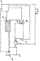
- FIG. 1 shows that in the oil pan of the oil-cooled engine by external energy, for. As electricity, by means of a heating element 5 preheated lubricating oil, for. B. from the oil pan 3, removed by means of temperature-resistant hose or pipe and a suitable, temperature-resistant and electrically driven pump 1 of the preheating circuit is supplied.
- This pump 1 generates a system pressure of about 10 bar and is constantly in operation during the stoppage of the internal combustion engine.
- a parallel pump is provided, which starts immediately in case of failure of the first pump and ensures that the preheated oil is constantly circulated.
- a safety valve 2 with an opening pressure of about 9 bar is mounted such that a derivative of the lubricating oil is ensured when the preset pressure is exceeded back into the oil pan or oil pump ,
- a check valve 12 with a low opening pressure (0.2 bar) prevents emptying of the external preheating circuit and thus influencing the oil level in the oil pan, especially in the level measurement of the oil pan by means of dipstick.
- This check valve 12th can be placed in front of or behind the external pump, depending on the suction capacity of the external pump.
- the lubricating oil in the oil pan 3 by means of the previously provided heating elements is conveyed into a pressure-resistant boiler tank 4, in which it by a thermostat controlled, with external energy, eg. B. electrically heated heating element 5 is heated to a sufficient for engine preheating temperature level.
- the heating element is protected by a suitable temperature monitoring means of temperature sensor 6, which communicates the control unit 11, the temperature of the oil, the control unit 11, the heating element 5 controls, so that it z. B. in case of failure of the feed pump 1 can not come to overheating of the boiler tank 4. In the case of reaching the upper limit temperature of the oil, the controller 11 turns off the heating element 5 to save power.
- additional temperature sensors located on the motor or close to the engine can be integrated into this safety circuit to protect against overheating.
- the preheated lubricating oil is fed into the lubricating oil circuit through a check valve 7, which is permanently resistant to temperature and has a temperature of up to 140 ° C. at a control pressure of about 1 bar at the point marked X.
- the check valve 7 prevents the start of the engine, a back flow of the lubricating oil in the preheating unit.
- the motors are equipped with a built-in oil circuit oil cooler 9, which is capable of dissipating the heat generated during normal engine heat, this can also act as overtemperature protection. Due to the existing in the engine thermostat 10 is included when reaching a sufficient engine temperature of the mounted oil cooler in the oil flow of the heater.
- the preheater 5 is turned off with the start of the engine.
- the oil pump 14 of the engine takes over the conveying function of the oil and heats the engine and its fluids during operation.
- a delayed switch-off is provided by an adjustable time stage.
- the combination of a temperature control and a speed control of the pump 1 is provided which is temperature-controlled and executed in combination with a pressure and temperature control, which has an advantageous effect on the operating costs.
- the cooling liquid of the engine is conveyed and preheated in a separate preheating circuit with its own pump 1 and own boiler tank 4 and a separate heating element 5 and the associated temperature sensor 6, which communicate with the control unit 11.
- the preheater 5 is turned off with the start of the engine or a delayed off by an adjustable timer is provided.
- the promotion of the fluids and thus the heating of the engine takes place in this embodiment by the oil pump 14 of the engine and the cooling water pump, not shown, of the engine.
- a microwave generator 5 microwave, 1.5 - 4.5 GHz
- FIG. 2 shows a microwave generator 5, which is arranged on the crankcase 19 of the internal combustion engine 16 and there through a glass window 20 through the coolant, for.
- the temperature in the crankcase of the engine 16 is determined by means of temperature sensor 15 and forwarded to the control unit 11.
- the control unit 11 sends a control signal to the microwave generator 5 and causes it to heat the cooling water through the glass window 20.
- the engine 16 has an engine coolant thermostat 10, which ensures that from a defined temperature, the cooling water can flow through the radiator 9.
- the cooler 9 has a temperature sensor 15, which forwards the cooler temperature to the control unit 11. From the cooler, the cooling water enters the boiler 17, whose cooling water temperature is forwarded by a temperature sensor 15 to the control unit.
- the boiler 17 has a pressure relief valve 18, which is to protect the boiler from excessive pressure.
- a cooling water pump 1 is arranged, which circulates the cooling water.
- FIG. 3 becomes a magnetron 5 as it is in FIG. 2 is arranged on the crankcase of the internal combustion engine 16 shown.
- a microwave generator 5 can be mounted anywhere on the water jacket.
- the attachment is at the bottom of the crankcase 19.
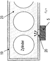
- a so-called "frost plug" can be replaced by a suitable window 20, as in FIG. 4 is pictured.
- the microwaves generated in the microwave generator penetrate through a sealed against the crankcase window made of glass, ceramic or plastic in the water jacket. They can reflect on the metallic walls of the crankcase and the cylinders and release their energy completely to the water as they travel through the water jacket. An unwanted leaving the microwaves from the water jacket is not possible because the water jacket is a hermetically sealed system. With an appropriate choice of power and the feeding point of the microwave generator there is also no risk of local overheating, because in the water jacket sets a natural convection, which leads to the distribution of heat.
- the power supply of the microwave generator would be done as in the resistance heating elements from an external power grid.
- the resistance heating elements only the power cord is removed after use, the heating element itself remains in or on the engine.
- the microwave generator 5 can be completely removed from the motor together with the power cord, since it does not have to be carried along when using the motor. Therefore, it is provided in an alternative embodiment that the microwave generator 5 are fastened with an easily operable plug or clamp connection. It can be used on commercial microwave generators, since no special demands on the robustness or compactness need to be made. In the case of a defect in the microwave generator, moreover, the cooling water does not need to be drained, which is the case with a defective resistance heating element.
Landscapes
- Engineering & Computer Science (AREA)
- Mechanical Engineering (AREA)
- General Engineering & Computer Science (AREA)
- Lubrication Of Internal Combustion Engines (AREA)
Description
- Die Erfindung betrifft eine Verbrennungskraftmaschine und ein Verfahren zum Betreiben derselben.
- Aus der
DE-PS 675 496 - Die
DE 44 02 215 A1 beschreibt ein Verfahren zur Verbesserung des Kaltstartverhaltens von Verbrennungskraftmaschinen durch Einkopplung von Wärmeenergie in das Maschinensystem sowie auf Einrichtungen zur Durchführung des Verfahrens. - Derartige Verbrennungskraftmaschinen sind aber auch aus der
EP 0 809 752 A1 bekannt. -
EP 0 634 565 A1 offenbart ein Verfahren zur Verbesserung des Kaltstartverhaltens von Verbrennungsmaschinen. - Daran ist nachteilig, dass bei tiefen Temperaturen eine ausreichende Vorwärmung des Gesamtmotors, die zum sofortigen Start unter Volllast notwendig wäre, nicht realisiert werden kann. Da nur der Ölwanneninhalt aufgeheizt wird, kann es durch die thermische Entkoppelung der Ölwanne samt Ölinhalt nicht zu einer ausreichenden Vorwärmung des Motorblocks kommen.
- Eine sofortige, vollständige Belastung des Motors ist nicht möglich, wie es z. B. für einen Notstromaggregateeinsatz bei einem Netzausfall insbesondere unter winterlichen Bedingungen notwendig wäre.
- Zur Kühlwasservorwärmung werden in Verbrennungsmotoren elektrische Widerstandsheizelemente verwendet. Man erwärmt damit bei Bedarf das Kühlwasser vor dem Motorstart und schaltet sie ab, sobald der Motor läuft bzw. wenn das Wasser eine gewisse Temperatur erreicht hat. Im Normalbetrieb sind sie ausgeschaltet, sie stehen aber ununterbrochen in der Wasserströmung und erzeugen einen unerwünschten Druckverlust. Dieser Druckverlust muss durch erhöhte Wasserpumpenleistung kompensiert werden und führt in der Praxis zu verringerten Kühlwassermengen und erhöhtem Kraftstoffverbrauch.
- Es ist die Aufgabe der vorliegenden Erfindung, eine Einrichtung zu schaffen, die es ermöglicht, einen Verbrennungsmotor derart vorzuwärmen, dass dieser in der Lage ist, einen Sofortstart sicher und ökonomisch zu absolvieren.
- Die Aufgabe wird insbesondere gemäß der Ansprüche 1 und 9 gelöst.
- Wieter ist erfindungsgemäß ein Motor vorgesehen, der mit einer Zusatzeinrichtung versehen ist, die es ermöglicht, dass das z. B. in der Ölwanne befindliche, mittels Fremdenergie beheizte Schmieröl bei Motorstillstand durch den Kühlmantel des Motors gepumpt wird.
- Hierdurch wird eine ausreichende Vorwärmung des Motors und Durchölung des Motors ermöglicht, so dass selbst bei tiefen Temperaturen ein spontaner Start des Motors mit sofortiger Lastbeaufschlagung möglich ist.
- Weitere wichtige Merkmale und Vorteile ergeben sich aus den Unteransprüchen, aus den Zeichnungen und aus der nachfolgenden Beschreibung eines bevorzugten Ausführungsbeispiels anhand der Zeichnungen. Es zeigen:
- Figur 1
- eine nicht erfindungsgemäße, schematische Darstellung bezüglich des Erwärmens des Motoröls
- Figur 2
- eine erfindungsgemäße, schematische Darstellung bezüglich des Erwärmens des Kühlwassers
- Figur 3
- ein Magnetron zur Mikrowellenerzeugung
- Figur 4
- ein am Kurbelgehäuse angeordnetes Magnetron zur Erwärmung des Kühlwassers.
-
Figur 1 zeigt, dass das in der Ölwanne des ölgekühlten Motors durch Fremdenergie, z. B. Elektrizität, mittels eines Heizelements 5 vorgeheizte Schmieröl, z. B. aus der Ölwanne 3, mittels temperaturbeständiger Schlauchleitung oder Rohrleitung entnommen und einer geeigneten, temperaturbeständigen und elektrisch angetriebenen Pumpe 1 des Vorwärmkreislaufs zugeführt wird. Diese Pumpe 1 erzeugt einen Systemdruck von etwa 10 bar und ist während des Stillstands der Verbrennungskraftmaschine ständig in Betrieb. In einer alternativen Ausgestaltung ist eine parallel angeordnete Pumpe vorgesehen, die im Störungsfall der ersten Pumpe sofort anspringt und sicherstellt, dass das vorzuwärmende Öl ständig umgewälzt wird. - Hinter dieser Druckölpumpe 1, die ein Öldruckniveau von ca. 10 bar erzeugen kann, wird ein Sicherheitsventil 2 mit einem Öffnungsdruck von ca. 9 bar derart angebaut, dass eine Ableitung des Schmieröls bei Überschreiten des voreingestellten Druckes zurück in die Ölwanne oder vor Ölpumpe gewährleistet ist.
- Dies ist notwendig, um bei kaltem Motor eine Beschädigung des Schmierölsystems, hier insbesondere des Schmierölfilters 13, beim Start der Vorwärmeinheit sicher ausschließen zu können.
- Ein Rückschlagventil 12 mit geringem Öffnungsdruck (0,2 bar) verhindert ein Leerlaufen des externen Vorwärmkreislaufes und somit eine Beeinflussung des Schmierölstandes in der Ölwanne, insbesondere bei der Füllstandsmessung der Ölwanne mittels Peilstab. Dieses Rückschlagventil 12 kann vor oder hinter der externen Pumpe, je nach Ansaugvermögen der externen Pumpe, angeordnet werden.
- Falls eine ausreichende Vorwärmung des Schmieröls in der Ölwanne 3 mittels der bisher vorgesehenen Heizelemente nicht darstellbar ist, wird das Schmieröl in einen druckfesten Boilertank 4 gefördert, in dem es durch ein thermostatgesteuertes, mit Fremdenergie, z. B. elektrisch, beheiztes Heizelement 5 auf ein zur Motorvorwärmung ausreichendes Temperaturniveau aufgeheizt wird.
- Das Heizelement wird durch eine geeignete Temperaturüberwachung abgesichert mittels Temperatursensor 6, der dem Steuergerät 11 die Temperatur des Öls mitteilt, wobei das Steuergerät 11 das Heizelement 5 ansteuert, so dass es z. B. beim Ausfall der Förderpumpe 1 nicht zu einer Überhitzung des Boilertanks 4 kommen kann. Im Fall des Erreichens der oberen Grenztemperatur des Öls schaltet das Steuergerät 11 das Heizelement 5 ab, um Strom zu sparen.
- In diese Sicherheitsschaltung können optional auch noch weitere Temperatursensoren, die sich am Motor oder in Motornähe befinden, zur Absicherung gegen Übertemperaturen eingebunden werden.
- Aus dem Boilertank wird das vorgewärmte Schmieröl durch ein bis zu 140°C dauerfest temperaturbeständiges Rückschlagventil 7 mit einem Regeldruck von etwa 1 bar an der mit X gekennzeichneten Stelle in den Schmierölkreislauf eingespeist.
- Hierdurch wird der Kühlmantel des Motors mit wärmendem Öl durchströmt und alle Schmierstellen bis hin zum Turbolader mit vorgewärmtem Schmieröl versorgt.
- Das Rückschlagventil 7 verhindert beim Start des Motors ein Rückfließen des Schmieröls in die Vorwärmeinheit.
- Durch die im Motorölkreislauf vorhandenen Druckregelventile 8 stellt sich ein Schmieröldruckniveau an den Lagerstellen wie im Motorbetrieb ein.
- Da die Motoren mit einem in den Ölkreislauf eingebundenen Ölkühler 9 ausgerüstet sind, der geeignet ist, die im Normalbetrieb entstehende Motorwärme abzuführen, kann dieser ebenfalls als Übertemperatursicherung fungieren. Durch den im Motor vorhandenen Thermostat 10 wird beim Erreichen einer ausreichenden Motortemperatur der angebaute Ölkühler in den Ölstrom der Heizvorrichtung mit einbezogen.
- Hierdurch ergibt sich eine zuverlässige Temperaturregelung für die Standby-Phase des Motors. Die Vorheizeinrichtung 5 wird mit dem Start des Motors ausgeschaltet. Beim Start des Motors übernimmt die Ölpumpe 14 des Motors die Förderfunktion des Öls und erwärmt den Motor und seine Fluide im laufenden Betrieb. In einer alternativen Ausgestaltung ist auch ein verzögertes Ausschalten durch eine einstellbare Zeitstufe vorgesehen. In einer weiteren alternativen Ausgestaltung ist die Kombination einer Temperaturregelung und einer Drehzahlregelung der Pumpe 1 vorgesehen, die temperaturgeregelt und auch in Kombination einer Druck- und Temperatursteuerung ausgeführt ist, was sich vorteilhaft auf die Betriebskosten auswirkt.
- In einer erfindungsgemäßen Ausgestaltung ist vorgesehen, dass die Kühlflüssigkeit des Motors in einem gesonderten Vorwärmkreislauf mit einer eigenen Pumpe 1 und einem eigenen Boilertank 4 sowie einem gesonderten Heizelement 5 und dem zugehörigen Temperatursensor 6, die mit dem Steuergerät 11 kommunizieren, gefördert und vorgewärmt wird. Auch hier wird die Vorheizeinrichtung 5 mit dem Start des Motors ausgeschaltet bzw. ist ein verzögertes Ausschalten durch eine einstellbare Zeitstufe vorgesehen. Die Förderung der Fluide und somit die Erwärmung des Motors erfolgt in diesem Ausführungsbeispiel durch die Ölpumpe 14 des Motors und die nicht dargestellte Kühlwasserpumpe des Motors. Mit einem Mikrowellengenerator 5 (Magnetron, 1,5 - 4,5 GHz) kann das Wasser berührungslos aufgewärmt werden. Somit wird im Normalbetrieb des Wasserkreislaufs auch kein Druckverlust erzeugt.
-
Figur 2 zeigt einen Mikrowellengenerator 5, der am Kurbelgehäuse 19 der Brennkraftmaschine 16 angeordnet ist und dort durch ein Glasfenster 20 hindurch das Kühlmittel, z. B. Kühlwasser 23, erwärmt. Die Temperatur im Kurbelgehäuse des Motors 16 wird mittels Temperatursensor 15 ermittelt und ans Steuergerät 11 weitergeleitet. Das Steuergerät 11 sendet beim Unterschreiten eines einstellbaren Temperaturwertes ein Steuersignal an den Mikrowellengenerator 5 und bringt diesen dazu, dass er das Kühlwasser durch das Glasfenster 20 hindurch erwärmt. Der Motor 16 weist einen Motorkühlmittelthermostat 10 auf, der dafür sorgt, dass ab einer definierten Temperatur das Kühlwasser durch den Kühler 9 strömen kann. Der Kühler 9 verfügt über einen Temperatursensor 15, der die Kühlertemperatur ans Steuergerät 11 weiterleitet. Vom Kühler gelangt das Kühlwasser in den Boiler 17, dessen Kühlwassertemperatur von einem Temperatursensor 15 ans Steuergerät weitergeleitet wird. Der Boiler 17 verfügt über ein Überdruckventil 18, das den Boiler vor zu hohen Drücken schützen soll. Zwischen dem Boiler 17 und dem Motor 16 bzw. dem Wassermantel 23 des Kurbelgehäuses 19 ist eine Kühlwasserpumpe 1 angeordnet, die das Kühlwasser zirkulieren lässt. - In
Figur 3 wird ein Magnetron 5, wie es inFigur 2 am Kurbelgehäuse der Brennkraftmaschine 16 angeordnet ist, gezeigt. Ein solcher Mikrowellengenerator 5 kann an einer beliebigen Stelle des Wassermantels angebracht werden. Optimal ist die Anbringung unten am Kurbelgehäuse 19. Beispielsweise kann ein sogenannter "Froststopfen" durch ein geeignetes Fenster 20 ersetzt werden, wie dies inFigur 4 dargestellt wird. - Die im Mikrowellengenerator erzeugten Mikrowellen dringen durch ein gegen das Kurbelgehäuse abgedichtetes Fenster aus Glas, Keramik oder Kunststoff in den Wassermantel ein. Sie können an den metallischen Wänden des Kurbelgehäuses und der Zylinder reflektieren und auf ihrem Weg durch den Wassermantel ihre Energie vollständig an das Wasser abgeben. Ein unerwünschtes Verlassen der Mikrowellen aus dem Wassermantel ist nicht möglich, da der Wassermantel ein hermetisch geschlossenes System ist. Bei angemessener Wahl der Leistung und der Einspeisungsstelle des Mikrowellengenerators besteht auch keine Gefahr der lokalen Überhitzung, da sich im Wassermantel eine natürliche Konvektion einstellt, die zur Verteilung der Wärme führt.
- Die Energieversorgung des Mikrowellengenerators würde wie bei den Widerstandsheizelementen aus einem externen Stromnetz erfolgen. Bei den Widerstandsheizelementen wird nach der Anwendung nur das Netzkabel abgezogen, das Heizelement selbst verbleibt im bzw. am Motor. Der Mikrowellengenerator 5 kann aber mitsamt dem Netzkabel komplett vom Motor entfernt werden, da er beim Einsatz des Motors nicht mitgeführt werden muss. Deshalb ist in einer alternativen Ausgestaltung vorgesehen, dass der Mikrowellengenerator 5 mit einer einfach zu betätigenden Steck- oder Klemmverbindung befestigt werden. Es kann auf handelsübliche Mikrowellengeneratoren zurückgegriffen werden, da keine besonderen Anforderungen an die Robustheit oder die Kompaktheit gestellt zu werden brauchen. Bei einem Defekt des Mikrowellengenerators braucht zudem das Kühlwasser nicht abgelassen zu werden, was bei einem defekten Widerstandsheizelement der Fall ist.
- Bezugszeichen
- 1
- Pumpe des Vorwärmkreislaufs
- 2
- Sicherheitsventil
- 3
- Ölwanne
- 4
- Boilertank
- 5
- Heizelement
- 6
- Temperatursensor
- 7
- Rückschlagventil
- 8
- Druckregelventil
- 9
- Motorkühlmittelwärmetauscher
- 10
- Motorkühlmittelthermostat
- 11
- Steuergerät
- 12
- Rückschlagventil
- 13
- Schmierölfilter
- 14
- Motorölpumpe
- 15
- Temperatursensor
- 16
- Motor
- 17
- Motorkühlmittelausgleichsbehälter
- 18
- Überdruckventil
- 19
- Kurbelgehäuse
- 20
- Fenster im Kurbelgehäuse
- 23
- Motorkühlmittel
Claims (9)
- Verbrennungskraftmaschine, insbesondere zum Schnellstart, umfassend wenigstens eine Heizvorrichtung (5) für Motorkühlmittel und wenigstens eine vom Verbrennungsbetrieb der Verbrennungskraftmaschine unabhängig zu betreibende Umwälzpumpe (1) zur Umwälzung des Motorenöls oder des Motorkühlmittels, wobei die Heizvorrichtung wenigstens einen elektrischen Mikrowellen-Generator aufweist, der am Kurbelgehäuse (19) der Brennkraftmaschine (16) angeordnet ist.
- Verbrennungskraftmaschine nach Anspruch 1 oder 2,
dadurch gekennzeichnet, dass sie als Kühlmittel Wasser und/oder Öl aufweist. - Verbrennungskraftmaschine nach einem oder mehreren der vorgenannten Ansprüche,
dadurch gekennzeichnet, dass die Heizvorrichtung (5) am Kühlwasserkreislauf oder an einem zusätzlichen Boilertank (4) angeordnet ist. - Verbrennungskraftmaschine nach einem oder mehreren der vorgenannten Ansprüche,
dadurch gekennzeichnet, dass sie wenigstens einen Temperatursensor (6) zur Ermittlung der Motorenöl- und/oder der Motorkühlmitteltemperatur aufweist. - Verbrennungskraftmaschine nach Anspruch 4 oder 5,
dadurch gekennzeichnet, dass sie wenigstens ein Rückschlagventil (7) im Motorenöl- und/oder im Motorkühlmittelkreislauf aufweist. - Verbrennungskraftmaschine nach den Ansprüchen 4 bis 6,
dadurch gekennzeichnet, dass sie wenigstens ein Sicherheitsventil (2) im Motorenöl- und/oder im Motorkühlmittelkreislauf aufweist. - Verbrennungskraftmaschine nach einem oder mehreren der vorgenannten Ansprüche,
dadurch gekennzeichnet, dass sie wenigstens einen Motorenöl- und/oder Motorkühlmittelwärmetauscher (9) aufweist. - Verbrennungskraftmaschine nach einem oder mehreren der vorgenannten Ansprüche,
dadurch gekennzeichnet, dass sie wenigstens einen Motorenöl- und/oder Motorkühlmittelthermostat (10) aufweist. - Verfahren zum Betreiben einer Verbrennungskraftmaschine,
dadurch gekennzeichnet, dass es eine Verbrennungskraftmaschine nach einem oder mehreren der vorgenannten Ansprüche aufweist und das Motorenöl und/oder das Motorkühlmittel insbesondere im Stillstandsbetrieb durch das Zusammenwirken von Heizvorrichtung (5) in elektrischer Verbindung mit Temperatursensor (6), Motorkühlmittelthermostat (10) auf Temperaturen von etwa 40 Grad Celsius bis 80 Grad Celsius erwärmt.
Applications Claiming Priority (2)
| Application Number | Priority Date | Filing Date | Title |
|---|---|---|---|
| DE201210025436 DE102012025436A1 (de) | 2012-12-21 | 2012-12-21 | Verbrennungskraftmaschine |
| PCT/EP2013/003808 WO2014095035A1 (de) | 2012-12-21 | 2013-12-17 | Verbrennungskraftmaschine |
Publications (2)
| Publication Number | Publication Date |
|---|---|
| EP2935811A1 EP2935811A1 (de) | 2015-10-28 |
| EP2935811B1 true EP2935811B1 (de) | 2018-09-26 |
Family
ID=49999862
Family Applications (1)
| Application Number | Title | Priority Date | Filing Date |
|---|---|---|---|
| EP13823935.5A Active EP2935811B1 (de) | 2012-12-21 | 2013-12-17 | Verbrennungskraftmaschine |
Country Status (3)
| Country | Link |
|---|---|
| EP (1) | EP2935811B1 (de) |
| DE (1) | DE102012025436A1 (de) |
| WO (1) | WO2014095035A1 (de) |
Families Citing this family (4)
| Publication number | Priority date | Publication date | Assignee | Title |
|---|---|---|---|---|
| FR3031139B1 (fr) * | 2014-12-29 | 2016-12-30 | Soc De Motorisations Aeronautiques | Procede de regulation de la temperature d'huile de lubrification d'un moteur |
| CN104747342A (zh) * | 2015-03-16 | 2015-07-01 | 山东钢铁股份有限公司 | 一种移动式自动恒温控制的内燃机车预热装置 |
| RU193278U1 (ru) * | 2019-06-26 | 2019-10-22 | Публичное акционерное общество "КАМАЗ" | Система предпускового подогрева двигателя внутреннего сгорания |
| US20230258111A1 (en) * | 2022-02-11 | 2023-08-17 | Stewart & Stevenson Llc | Natural gas fluid heating pre-start system |
Family Cites Families (11)
| Publication number | Priority date | Publication date | Assignee | Title |
|---|---|---|---|---|
| DE675496C (de) | 1937-10-24 | 1939-05-10 | Maschf Augsburg Nuernberg Ag | Kuehl- und Schmiereinrichtung fuer Brennkraftmaschinenanlagen, insbesondere Notstrom- anlagen, mit zwei getrennten Einrichtungen, die je Kuehl- und Schmiermittel foerdern |
| US3134374A (en) * | 1963-08-26 | 1964-05-26 | James H Stevens | Oil and water preheater for internal combustion engines |
| DE3341097A1 (de) * | 1983-11-12 | 1985-05-23 | Volkswagenwerk Ag, 3180 Wolfsburg | Brennkraftmaschine fuer fahrzeuge, insbesondere personenkraftfahrzeuge |
| US4940114A (en) * | 1989-09-05 | 1990-07-10 | Albrecht Kenneth D | Engine prelubricating system |
| DE4402215A1 (de) * | 1993-07-12 | 1995-01-19 | Man Nutzfahrzeuge Ag | Verfahren zur Verbesserung des Kaltstartverhaltens von Verbrennungsmaschinen |
| JP3850873B2 (ja) | 1995-02-17 | 2006-11-29 | ジェイ. ホリス,トマス | エンジンオイルを最適温度に維持するためのシステム |
| DE19645278B4 (de) * | 1995-11-11 | 2005-04-28 | Volkswagen Ag | Vorrichtung zum Beheizen des Antriebsaggregates von Kraftfahrzeugen |
| DE19701094A1 (de) * | 1997-01-15 | 1998-07-16 | Behr Gmbh & Co | Zusatzheizung für Kraftfahrzeuge |
| CA2479636A1 (en) * | 2004-08-31 | 2006-02-28 | Dryair Inc. | Method and apparatus for maintaining warm engine temperature |
| DE102009013943A1 (de) * | 2009-03-19 | 2010-09-23 | Frank Will | Ölschmiersystem |
| EP2312132A1 (de) * | 2009-10-09 | 2011-04-20 | Alina Valentina Baciu | Motorvorrichtung zur diskontinuierlichen Verwendung |
-
2012
- 2012-12-21 DE DE201210025436 patent/DE102012025436A1/de not_active Withdrawn
-
2013
- 2013-12-17 EP EP13823935.5A patent/EP2935811B1/de active Active
- 2013-12-17 WO PCT/EP2013/003808 patent/WO2014095035A1/de not_active Ceased
Non-Patent Citations (1)
| Title |
|---|
| None * |
Also Published As
| Publication number | Publication date |
|---|---|
| WO2014095035A1 (de) | 2014-06-26 |
| EP2935811A1 (de) | 2015-10-28 |
| DE102012025436A1 (de) | 2014-06-26 |
Similar Documents
| Publication | Publication Date | Title |
|---|---|---|
| DE102015119304B4 (de) | Verbrennungsmotorkühlsystem und verfahren zum betreiben eines verbrennungsmotorkühlsystems | |
| DE102011084632B4 (de) | Verfahren zum Erwärmen einer Brennkraftmaschine und Brennkraftmaschine zur Durchführung eines derartigen Verfahrens | |
| WO2014095035A1 (de) | Verbrennungskraftmaschine | |
| EP0634565A1 (de) | Verfahren zur Verbesserung des Kaltstartverhaltens von Verbrennungsmaschinen | |
| EP2565334B1 (de) | Baumaschine mit ölgekühltem Generator | |
| DE102013208676B4 (de) | Flüssigkeitsgekühlte Brennkraftmaschine mit Kühlmittelkreislauf und Verfahren zum Betreiben einer derartigen Brennkraftmaschine | |
| DE102014220816A1 (de) | Vorrichtung zum Erwärmen eines Schmiermittels einer Brennkraftmaschine | |
| DE2507281A1 (de) | Elektrische zentral-speicherheizung | |
| EP1936298B1 (de) | Siphonfrostschutzeinrichtung | |
| DE102004061426A1 (de) | System und Verfahren zum Temperieren eines Motoröls einer Brennkraftmaschine eines Kraftfahrzeugs | |
| DE102017209484B4 (de) | Kühlvorrichtung, Kraftfahrzeug und Verfahren zum Betreiben einer Kühlvorrichtung | |
| DE102008057828A1 (de) | Fluggasturbinen-Ölsystemerwärmung | |
| DE19631981B4 (de) | Vorrichtung zum Kühlen eines Kraftstoffes eines geschlossenen Kraftstoffversorgungskreislaufes eines Dieselaggregats | |
| DE19635220A1 (de) | Steuerungseinheit für Dieselmotoren, die mit Fetten und Ölen von Pflanze und Tier betrieben werden | |
| DE102015106336A1 (de) | Wärmekreislauf für eine Antriebsvorrichtung eines Fahrzeugs | |
| AT513999B1 (de) | Abwärmenutzungssystem, insbesondere für ein Kraftfahrzeug, mit einer Speisepumpe | |
| DE102011009750A1 (de) | Verfahren zum Betrieb eines Heizgerätes | |
| DE112014004338T5 (de) | Kühlsystem in einem Fahrzeug | |
| DE102007055496A1 (de) | Baugruppe eines Kraftfahrzeugs | |
| DE102022101131B4 (de) | Elektromotorische Antriebseinheit mit schaltbarem Wärmetauscher zur energieoptimalen Verteilung von Wärmeenergie | |
| DE102008020637B4 (de) | Warmwasserversorgungsanlage mit einem Warmwasserspeicher | |
| EP4031761B1 (de) | Kaltstart-system für ein mit verdichtetem gas betriebenes fahrzeug mit einer monovalenten kraftstoffversorgung | |
| DE102007044165A1 (de) | Vorrichtung zum Betrieb von Motoranlagen mit Pflanzenöl | |
| DE102014209031B4 (de) | Kraftfahrzeug mit einer einen Wärmespeicher aufweisenden Temperiervorrichtung | |
| EP3204482B1 (de) | Lebensmitteltechnische prozessanlage, insbesondere brauereianlage mit blockheizkraft |
Legal Events
| Date | Code | Title | Description |
|---|---|---|---|
| PUAI | Public reference made under article 153(3) epc to a published international application that has entered the european phase |
Free format text: ORIGINAL CODE: 0009012 |
|
| 17P | Request for examination filed |
Effective date: 20150529 |
|
| AK | Designated contracting states |
Kind code of ref document: A1 Designated state(s): AL AT BE BG CH CY CZ DE DK EE ES FI FR GB GR HR HU IE IS IT LI LT LU LV MC MK MT NL NO PL PT RO RS SE SI SK SM TR |
|
| AX | Request for extension of the european patent |
Extension state: BA ME |
|
| DAX | Request for extension of the european patent (deleted) | ||
| 17Q | First examination report despatched |
Effective date: 20161222 |
|
| GRAP | Despatch of communication of intention to grant a patent |
Free format text: ORIGINAL CODE: EPIDOSNIGR1 |
|
| INTG | Intention to grant announced |
Effective date: 20180425 |
|
| GRAS | Grant fee paid |
Free format text: ORIGINAL CODE: EPIDOSNIGR3 |
|
| GRAA | (expected) grant |
Free format text: ORIGINAL CODE: 0009210 |
|
| AK | Designated contracting states |
Kind code of ref document: B1 Designated state(s): AL AT BE BG CH CY CZ DE DK EE ES FI FR GB GR HR HU IE IS IT LI LT LU LV MC MK MT NL NO PL PT RO RS SE SI SK SM TR |
|
| REG | Reference to a national code |
Ref country code: GB Ref legal event code: FG4D Free format text: NOT ENGLISH |
|
| REG | Reference to a national code |
Ref country code: CH Ref legal event code: EP |
|
| REG | Reference to a national code |
Ref country code: AT Ref legal event code: REF Ref document number: 1046280 Country of ref document: AT Kind code of ref document: T Effective date: 20181015 |
|
| REG | Reference to a national code |
Ref country code: IE Ref legal event code: FG4D Free format text: LANGUAGE OF EP DOCUMENT: GERMAN |
|
| REG | Reference to a national code |
Ref country code: DE Ref legal event code: R096 Ref document number: 502013011201 Country of ref document: DE |
|
| REG | Reference to a national code |
Ref country code: NL Ref legal event code: MP Effective date: 20180926 |
|
| PG25 | Lapsed in a contracting state [announced via postgrant information from national office to epo] |
Ref country code: SE Free format text: LAPSE BECAUSE OF FAILURE TO SUBMIT A TRANSLATION OF THE DESCRIPTION OR TO PAY THE FEE WITHIN THE PRESCRIBED TIME-LIMIT Effective date: 20180926 Ref country code: RS Free format text: LAPSE BECAUSE OF FAILURE TO SUBMIT A TRANSLATION OF THE DESCRIPTION OR TO PAY THE FEE WITHIN THE PRESCRIBED TIME-LIMIT Effective date: 20180926 Ref country code: NO Free format text: LAPSE BECAUSE OF FAILURE TO SUBMIT A TRANSLATION OF THE DESCRIPTION OR TO PAY THE FEE WITHIN THE PRESCRIBED TIME-LIMIT Effective date: 20181226 Ref country code: GR Free format text: LAPSE BECAUSE OF FAILURE TO SUBMIT A TRANSLATION OF THE DESCRIPTION OR TO PAY THE FEE WITHIN THE PRESCRIBED TIME-LIMIT Effective date: 20181227 Ref country code: FI Free format text: LAPSE BECAUSE OF FAILURE TO SUBMIT A TRANSLATION OF THE DESCRIPTION OR TO PAY THE FEE WITHIN THE PRESCRIBED TIME-LIMIT Effective date: 20180926 Ref country code: LT Free format text: LAPSE BECAUSE OF FAILURE TO SUBMIT A TRANSLATION OF THE DESCRIPTION OR TO PAY THE FEE WITHIN THE PRESCRIBED TIME-LIMIT Effective date: 20180926 Ref country code: BG Free format text: LAPSE BECAUSE OF FAILURE TO SUBMIT A TRANSLATION OF THE DESCRIPTION OR TO PAY THE FEE WITHIN THE PRESCRIBED TIME-LIMIT Effective date: 20181226 |
|
| REG | Reference to a national code |
Ref country code: LT Ref legal event code: MG4D |
|
| PG25 | Lapsed in a contracting state [announced via postgrant information from national office to epo] |
Ref country code: AL Free format text: LAPSE BECAUSE OF FAILURE TO SUBMIT A TRANSLATION OF THE DESCRIPTION OR TO PAY THE FEE WITHIN THE PRESCRIBED TIME-LIMIT Effective date: 20180926 Ref country code: HR Free format text: LAPSE BECAUSE OF FAILURE TO SUBMIT A TRANSLATION OF THE DESCRIPTION OR TO PAY THE FEE WITHIN THE PRESCRIBED TIME-LIMIT Effective date: 20180926 Ref country code: LV Free format text: LAPSE BECAUSE OF FAILURE TO SUBMIT A TRANSLATION OF THE DESCRIPTION OR TO PAY THE FEE WITHIN THE PRESCRIBED TIME-LIMIT Effective date: 20180926 |
|
| PG25 | Lapsed in a contracting state [announced via postgrant information from national office to epo] |
Ref country code: RO Free format text: LAPSE BECAUSE OF FAILURE TO SUBMIT A TRANSLATION OF THE DESCRIPTION OR TO PAY THE FEE WITHIN THE PRESCRIBED TIME-LIMIT Effective date: 20180926 Ref country code: IT Free format text: LAPSE BECAUSE OF FAILURE TO SUBMIT A TRANSLATION OF THE DESCRIPTION OR TO PAY THE FEE WITHIN THE PRESCRIBED TIME-LIMIT Effective date: 20180926 Ref country code: PL Free format text: LAPSE BECAUSE OF FAILURE TO SUBMIT A TRANSLATION OF THE DESCRIPTION OR TO PAY THE FEE WITHIN THE PRESCRIBED TIME-LIMIT Effective date: 20180926 Ref country code: CZ Free format text: LAPSE BECAUSE OF FAILURE TO SUBMIT A TRANSLATION OF THE DESCRIPTION OR TO PAY THE FEE WITHIN THE PRESCRIBED TIME-LIMIT Effective date: 20180926 Ref country code: ES Free format text: LAPSE BECAUSE OF FAILURE TO SUBMIT A TRANSLATION OF THE DESCRIPTION OR TO PAY THE FEE WITHIN THE PRESCRIBED TIME-LIMIT Effective date: 20180926 Ref country code: IS Free format text: LAPSE BECAUSE OF FAILURE TO SUBMIT A TRANSLATION OF THE DESCRIPTION OR TO PAY THE FEE WITHIN THE PRESCRIBED TIME-LIMIT Effective date: 20190126 Ref country code: NL Free format text: LAPSE BECAUSE OF FAILURE TO SUBMIT A TRANSLATION OF THE DESCRIPTION OR TO PAY THE FEE WITHIN THE PRESCRIBED TIME-LIMIT Effective date: 20180926 Ref country code: EE Free format text: LAPSE BECAUSE OF FAILURE TO SUBMIT A TRANSLATION OF THE DESCRIPTION OR TO PAY THE FEE WITHIN THE PRESCRIBED TIME-LIMIT Effective date: 20180926 |
|
| PG25 | Lapsed in a contracting state [announced via postgrant information from national office to epo] |
Ref country code: SK Free format text: LAPSE BECAUSE OF FAILURE TO SUBMIT A TRANSLATION OF THE DESCRIPTION OR TO PAY THE FEE WITHIN THE PRESCRIBED TIME-LIMIT Effective date: 20180926 Ref country code: SM Free format text: LAPSE BECAUSE OF FAILURE TO SUBMIT A TRANSLATION OF THE DESCRIPTION OR TO PAY THE FEE WITHIN THE PRESCRIBED TIME-LIMIT Effective date: 20180926 Ref country code: PT Free format text: LAPSE BECAUSE OF FAILURE TO SUBMIT A TRANSLATION OF THE DESCRIPTION OR TO PAY THE FEE WITHIN THE PRESCRIBED TIME-LIMIT Effective date: 20190126 |
|
| REG | Reference to a national code |
Ref country code: DE Ref legal event code: R097 Ref document number: 502013011201 Country of ref document: DE |
|
| PG25 | Lapsed in a contracting state [announced via postgrant information from national office to epo] |
Ref country code: DK Free format text: LAPSE BECAUSE OF FAILURE TO SUBMIT A TRANSLATION OF THE DESCRIPTION OR TO PAY THE FEE WITHIN THE PRESCRIBED TIME-LIMIT Effective date: 20180926 |
|
| REG | Reference to a national code |
Ref country code: CH Ref legal event code: PL |
|
| PLBE | No opposition filed within time limit |
Free format text: ORIGINAL CODE: 0009261 |
|
| STAA | Information on the status of an ep patent application or granted ep patent |
Free format text: STATUS: NO OPPOSITION FILED WITHIN TIME LIMIT |
|
| GBPC | Gb: european patent ceased through non-payment of renewal fee |
Effective date: 20181226 |
|
| PG25 | Lapsed in a contracting state [announced via postgrant information from national office to epo] |
Ref country code: MC Free format text: LAPSE BECAUSE OF FAILURE TO SUBMIT A TRANSLATION OF THE DESCRIPTION OR TO PAY THE FEE WITHIN THE PRESCRIBED TIME-LIMIT Effective date: 20180926 Ref country code: LU Free format text: LAPSE BECAUSE OF NON-PAYMENT OF DUE FEES Effective date: 20181217 |
|
| 26N | No opposition filed |
Effective date: 20190627 |
|
| REG | Reference to a national code |
Ref country code: IE Ref legal event code: MM4A |
|
| REG | Reference to a national code |
Ref country code: BE Ref legal event code: MM Effective date: 20181231 |
|
| PG25 | Lapsed in a contracting state [announced via postgrant information from national office to epo] |
Ref country code: FR Free format text: LAPSE BECAUSE OF NON-PAYMENT OF DUE FEES Effective date: 20181231 Ref country code: SI Free format text: LAPSE BECAUSE OF FAILURE TO SUBMIT A TRANSLATION OF THE DESCRIPTION OR TO PAY THE FEE WITHIN THE PRESCRIBED TIME-LIMIT Effective date: 20180926 Ref country code: IE Free format text: LAPSE BECAUSE OF NON-PAYMENT OF DUE FEES Effective date: 20181217 |
|
| PG25 | Lapsed in a contracting state [announced via postgrant information from national office to epo] |
Ref country code: BE Free format text: LAPSE BECAUSE OF NON-PAYMENT OF DUE FEES Effective date: 20181231 |
|
| PG25 | Lapsed in a contracting state [announced via postgrant information from national office to epo] |
Ref country code: CH Free format text: LAPSE BECAUSE OF NON-PAYMENT OF DUE FEES Effective date: 20181231 Ref country code: LI Free format text: LAPSE BECAUSE OF NON-PAYMENT OF DUE FEES Effective date: 20181231 Ref country code: GB Free format text: LAPSE BECAUSE OF NON-PAYMENT OF DUE FEES Effective date: 20181226 |
|
| PG25 | Lapsed in a contracting state [announced via postgrant information from national office to epo] |
Ref country code: MT Free format text: LAPSE BECAUSE OF FAILURE TO SUBMIT A TRANSLATION OF THE DESCRIPTION OR TO PAY THE FEE WITHIN THE PRESCRIBED TIME-LIMIT Effective date: 20180926 |
|
| REG | Reference to a national code |
Ref country code: AT Ref legal event code: MM01 Ref document number: 1046280 Country of ref document: AT Kind code of ref document: T Effective date: 20181217 |
|
| PG25 | Lapsed in a contracting state [announced via postgrant information from national office to epo] |
Ref country code: TR Free format text: LAPSE BECAUSE OF FAILURE TO SUBMIT A TRANSLATION OF THE DESCRIPTION OR TO PAY THE FEE WITHIN THE PRESCRIBED TIME-LIMIT Effective date: 20180926 |
|
| PG25 | Lapsed in a contracting state [announced via postgrant information from national office to epo] |
Ref country code: AT Free format text: LAPSE BECAUSE OF NON-PAYMENT OF DUE FEES Effective date: 20181217 |
|
| PG25 | Lapsed in a contracting state [announced via postgrant information from national office to epo] |
Ref country code: CY Free format text: LAPSE BECAUSE OF FAILURE TO SUBMIT A TRANSLATION OF THE DESCRIPTION OR TO PAY THE FEE WITHIN THE PRESCRIBED TIME-LIMIT Effective date: 20180926 Ref country code: MK Free format text: LAPSE BECAUSE OF NON-PAYMENT OF DUE FEES Effective date: 20180926 Ref country code: HU Free format text: LAPSE BECAUSE OF FAILURE TO SUBMIT A TRANSLATION OF THE DESCRIPTION OR TO PAY THE FEE WITHIN THE PRESCRIBED TIME-LIMIT; INVALID AB INITIO Effective date: 20131217 |
|
| PGFP | Annual fee paid to national office [announced via postgrant information from national office to epo] |
Ref country code: DE Payment date: 20251204 Year of fee payment: 13 |