EP2934993B1 - Human powered land vehicle - Google Patents
Human powered land vehicle Download PDFInfo
- Publication number
- EP2934993B1 EP2934993B1 EP12813862.5A EP12813862A EP2934993B1 EP 2934993 B1 EP2934993 B1 EP 2934993B1 EP 12813862 A EP12813862 A EP 12813862A EP 2934993 B1 EP2934993 B1 EP 2934993B1
- Authority
- EP
- European Patent Office
- Prior art keywords
- vehicle
- longitudinal beam
- vehicle according
- rear wheel
- longitudinal
- Prior art date
- Legal status (The legal status is an assumption and is not a legal conclusion. Google has not performed a legal analysis and makes no representation as to the accuracy of the status listed.)
- Not-in-force
Links
Images


Classifications
-
- B—PERFORMING OPERATIONS; TRANSPORTING
- B62—LAND VEHICLES FOR TRAVELLING OTHERWISE THAN ON RAILS
- B62K—CYCLES; CYCLE FRAMES; CYCLE STEERING DEVICES; RIDER-OPERATED TERMINAL CONTROLS SPECIALLY ADAPTED FOR CYCLES; CYCLE AXLE SUSPENSIONS; CYCLE SIDECARS, FORECARS, OR THE LIKE
- B62K3/00—Bicycles
- B62K3/005—Recumbent-type bicycles
-
- B—PERFORMING OPERATIONS; TRANSPORTING
- B62—LAND VEHICLES FOR TRAVELLING OTHERWISE THAN ON RAILS
- B62K—CYCLES; CYCLE FRAMES; CYCLE STEERING DEVICES; RIDER-OPERATED TERMINAL CONTROLS SPECIALLY ADAPTED FOR CYCLES; CYCLE AXLE SUSPENSIONS; CYCLE SIDECARS, FORECARS, OR THE LIKE
- B62K3/00—Bicycles
- B62K3/02—Frames
- B62K3/10—Frames of single-beam type, i.e. connecting steering head to rear axle
-
- B—PERFORMING OPERATIONS; TRANSPORTING
- B62—LAND VEHICLES FOR TRAVELLING OTHERWISE THAN ON RAILS
- B62K—CYCLES; CYCLE FRAMES; CYCLE STEERING DEVICES; RIDER-OPERATED TERMINAL CONTROLS SPECIALLY ADAPTED FOR CYCLES; CYCLE AXLE SUSPENSIONS; CYCLE SIDECARS, FORECARS, OR THE LIKE
- B62K5/00—Cycles with handlebars, equipped with three or more main road wheels
- B62K5/02—Tricycles
- B62K5/05—Tricycles characterised by a single rear wheel
-
- B—PERFORMING OPERATIONS; TRANSPORTING
- B62—LAND VEHICLES FOR TRAVELLING OTHERWISE THAN ON RAILS
- B62K—CYCLES; CYCLE FRAMES; CYCLE STEERING DEVICES; RIDER-OPERATED TERMINAL CONTROLS SPECIALLY ADAPTED FOR CYCLES; CYCLE AXLE SUSPENSIONS; CYCLE SIDECARS, FORECARS, OR THE LIKE
- B62K5/00—Cycles with handlebars, equipped with three or more main road wheels
- B62K5/02—Tricycles
- B62K5/06—Frames for tricycles
-
- B—PERFORMING OPERATIONS; TRANSPORTING
- B62—LAND VEHICLES FOR TRAVELLING OTHERWISE THAN ON RAILS
- B62K—CYCLES; CYCLE FRAMES; CYCLE STEERING DEVICES; RIDER-OPERATED TERMINAL CONTROLS SPECIALLY ADAPTED FOR CYCLES; CYCLE AXLE SUSPENSIONS; CYCLE SIDECARS, FORECARS, OR THE LIKE
- B62K5/00—Cycles with handlebars, equipped with three or more main road wheels
- B62K5/08—Cycles with handlebars, equipped with three or more main road wheels with steering devices acting on two or more wheels
-
- B—PERFORMING OPERATIONS; TRANSPORTING
- B62—LAND VEHICLES FOR TRAVELLING OTHERWISE THAN ON RAILS
- B62M—RIDER PROPULSION OF WHEELED VEHICLES OR SLEDGES; POWERED PROPULSION OF SLEDGES OR SINGLE-TRACK CYCLES; TRANSMISSIONS SPECIALLY ADAPTED FOR SUCH VEHICLES
- B62M6/00—Rider propulsion of wheeled vehicles with additional source of power, e.g. combustion engine or electric motor
- B62M6/40—Rider propelled cycles with auxiliary electric motor
- B62M6/70—Rider propelled cycles with auxiliary electric motor power-driven at single endless flexible member, e.g. chain, between cycle crankshaft and wheel axle, the motor engaging the endless flexible member
Definitions
- the invention relates to a human powered land vehicle with two steered front wheels and one rear wheel driven by a drive train, which drive train incorporates a human powered actuator to be actuated for propulsion of the vehicle by a person driving the vehicle and kinematically coupled to a driven wheel for propulsing the vehicle in at least one driving direction and which vehicle further disposes of a non-human powered actuator arranged to drive at least one of the wheels of the vehicle, and with at least one longitudinal beam and a cross-beam, whereas the rear wheel is connected to the longitudinal beam and the front wheels are supported by the cross-beam and whereas at least part of the drive train is being housed within the longitudinal beam, a seat is supported by the longitudinal beam and is designed that the person driving the vehicle is in a sitting position.
- Typical pedal propulsed land vehicles are bicycles (pedal propulsed land vehicles with two wheels) or tricycles (pedal propulsed land vehicles with three wheels).
- tricycles are three-wheeled bicycles, in which the driver typically is positioned in a laying-down position, similar to a two-wheel recumbent bicycle.
- Such tricycles typically have two front wheels and a rear wheel driven by a pedal drive. The front wheels are steered.
- Such vehicles may comprise a cover, typically made of a flexible canvas or of a rigid panel such as fibre-reinforced plastic material. Both embodiments may also cover the front of the vehicle. Then a windshield is implemented into such cover.
- the drive train for propulsing the vehicle with muscular power comprises a pedal drive arranged with its axis in front of the axles of the two front wheels.
- the pedal drive has a chain as driving means, which in turn drives a drive wheel on the rear wheel.
- the chain is arranged with a short distance to the longitudinal beam.
- the motor also drives the rear wheel.
- the motor drive is coupled to the axle of the rear wheel with a centrifugal clutch. According to this concept, the muscular force and the driving force of the motor are actuating the rear wheel in a parallel manner.
- the vehicle is either driven only by muscular force or by using the motor.
- This prior art land vehicle comprises a longitudinal beam and a cross-beam.
- the cross-beam carries the two steered front wheels.
- the longitudinal beam extends with a section in front of the front wheel.
- the pedal drive is arranged at the foremost end of the longitudinal beam.
- the back-wheel is linked to the longitudinal beam by way of a rocker arm connected to the longitudinal beam and movable around a horizontal axis extending in the transverse direction of the vehicle.
- the rear wheel being connected by way of a lever to the rest of the longitudinal beam, comprises a spring-damper element.
- the electric motor is directly coupled to the rear wheel and is hanging on the axle of the rear wheel.
- the seat for the driver is arranged approximately in the middle between the front wheels and the rear wheel.
- the beams of this vehicle are - as this is common in the construction of bicycles - manufactured from tubes.
- a human powered land vehicle according to the preamble of claim 1 is disclosed in DE 198 41 780 A1 .
- the human powered land vehicle according to this document at least part of the drive train is being housed within the longitudinal beam.
- the longitudinal beam supports a seat. The vehicle and the seat are designed, that the person drives the vehicle in a sitting position.
- a pedal propulsed land vehicle which disposes of an electric motor as non-human powered actuator also arranged to drive for instance the rear wheel as driven wheel, which may not only be designed to show a rather short length, but which may also be designed respecting the requirements as to light-weight and which may provide an unrivalled comfort.
- a longitudinal beam which is principally U-shaped in cross-section, not only provides a beam with very good support, strength and stiffness capability, but in itself provides a housing for at least part of the drive train. Also it may provide a housing for hydraulic piping, brake cables, steering elements and electrical wiring.
- the longitudinal beam constitutes a good base to support and/or carry other elements of the vehicle.
- This is for instance a pedal drive housing, which houses the pedal drive and is arranged with distance to the top of the longitudinal beam. A part of the drive train driving the rear wheel will thus be housed in the pedal drive housing and in the inside of the longitudinal beam.
- the pedals of the pedal drive are outside the pedal drive housing and arranged to be contacted by the feet of a person sitting on the seat to apply the force needed to turn the pedals. Therefore with such arrangement the inside of the vehicle being used by the driver may be free of any parts or elements of the drive train, except the pedals themselves.
- the drive train is segmented into several drive train segments, one of which is the pedal drive. Between two drive train segments the driving force of a first drive train segment is transferred to a second drive train segment.
- This feature is in this specific embodiment used to arrange two drive train segments angular to each other and thus to adapt the design of the drive train to the space available.
- the seat for seating the driver is conceived to accommodate the driver in a sitting position, not in a laying position. This is in many cases more advantageous than a laying position, in particular when driving in a city.
- the overall view of a driver in the sitting position is a lot better than in a laying position.
- the distance between the seat and the human powered actuator, for instance a pedal drive can be designed rather small. This allows the human powered actuator to be arranged as far back as being between the two front wheels, allowing reducing the overall length of such vehicle remarkably compared to prior art vehicles of the kind.
- the shorter length reduces the overall weight of the vehicle, not only in that the longitudinal beam can be designed shorter, but also in that a cover of the vehicle, which is preferably existent, is shorter and that due to this issue less material is needed.
- the longitudinal opening at the bottom side of the longitudinal beam need to be closed completely or in part, this can be done by applying one or more light-weight covers, which do not need to meet any strength requirements.
- the longitudinal beam is housing a part of the drive system, the therefore needed height of this beam already provides substantial vertical stiffness.
- the cross-beam supporting the front wheels carries front wheel support parts, which extend from the cross-beam in a vertical direction.
- these front wheel support parts are linked with each other by a bracket extending in height and in the traverse direction of the vehicle.
- This bracket may serve as support for other items used or needed in the vehicle, for example to hold one or more battery cases containing batteries to power the electric motor, and also provides extra vehicle stiffness and protects the driver in case of fall over or frontal and/or side collision.
- the longitudinal beam is a sheet-metal construction.
- Part of such construction is a rear wheel support, to which the rear wheel is mounted.
- the rear wheel support may be mounted pivotally movable around a vertical axis to the adjacent parts of the longitudinal beam allowing the rear wheel to be steered.
- Such steering action is linked to the steering action applied to the front wheels in that the rear wheel is steered in the opposite direction.
- Such steering action acting on the rear wheel is only a fraction of the steering action applied to the front wheels.
- the possible steering action of the rear wheel will be limited to a few degrees deviating from the neutral position.
- the seat is arranged on top or approximately on top of the electric motor, preferably in the longitudinal extension of the vehicle in front of the rear wheel.
- Arranging the electric motor in the longitudinal direction of the vehicle in front of the rear wheel which is in contrast to prior art vehicles of the kind, enhances the weight distribution within the vehicle, bringing the weight more to the centre of the vehicle. This results in a better driving comfort and easier handling of the vehicle.
- the longitudinal beam may also be used to attach and hold a rear support extending over the rear wheel.
- a rear support may for instance be used to fasten a cover and may be used as a support for luggage or for a child seat.
- a pedal propulsed land vehicle 1 designed to enhance in particular urban mobility is designed to have three wheels.
- the rear wheel 2 and the right front wheel 3 are to be seen.
- the wheels 2, 3 are borne on a chassis 4, which will be described later.
- the chassis 4 is covered by a cover 5.
- the cover 5 is manufactured of plastic material, which may be fiber-reinforced.
- the cover depicted in figure 1 covers the chassis 4 as to the front, the top and the back.
- the right side and the left side are kept open.
- the front of the cover 5 is translucent. This wind shield part of the cover 5 is identified with reference numeral 6.
- the backside of the cover 5 incorporates a rear window.
- the chassis 4 supports a seat 7, which is depicted in figure 1 in three of its possible positions.
- the positions of the seat 7 alter as to their height and their position with respect to the longitudinal extension of the vehicle 1.
- the two front wheels 3 of the vehicle 1 are steered.
- the steering gear comprises a steering wheel 8, which is connected in a not depicted manner to a steering gear steering the front wheels 3.
- the chassis 4 of the vehicle 1 disposes of a central beam 9 extending in longitudinal direction from the front of the vehicle 1 to the axle of the rear wheel 2.
- the longitudinal beam 9 is U- or C-shaped in cross-section, with its longitudinal opening facing groundwards.
- Attached to the longitudinal beam 9 is a cross-beam 10 extending width-wise to the vehicle.
- the cross-beam 10 carries the front wheels 3, 3.1 (see figures 2, 3 ).
- Mounted on the cross-beam 10 is a mounting bracket 11 linking the bearings of the front wheels 3, 3.1 over the topside of the beam 9.
- a pedal drive housing 12 Mounted on the topside of the beam 9 between the two front wheels 3, 3.1 is a pedal drive housing 12, also bearing a pedal drive 13.
- the vehicle 1 has a power train to drive the rear wheel 2, which power train is in the depicted embodiment divided into three drive train segments 14, 14.1, 14.2.
- a first drive train segment 14 drives the axle 15 of an electric motor 16.
- the axle 15 of the electric motor 16 drives the rear wheel 2 via the second drive train segment 14.1.
- the driving means of the second drive train segment 14.1 is in the depicted embodiment a chain 17 receiving its movement by rotation of the axle 15. Therefore, the chain 17 is driven by a chain wheel 18 sitting on the axle 15.
- a second chain wheel 19 is arranged on the axle of the rear wheel 2 to receive the driving force.
- Incorporated into the axle of the rear wheel 2 is a gear hub 20.
- the driving force received by the chain wheel 19 is transferred through the gear hub 20 and then brings the rear wheel 2 into rotational movement.
- the gear hub 20 may be actuated by the driver.
- the first drive train segment 14 comprises a chain 21 as driving means driving a chain wheel 22 also sitting on the axle 15 of the electric motor 16.
- the chain wheel 22 is a free-wheel. Therefore, driving force may only be transferred from the chain 21 to the axle 15 in one direction of rotation. This is the direction for propulsing the vehicle 1 into a forward movement.
- the first drive train segment 14 is itself driven by a third drive train segment 14.2, which incorporates the pedal drive 13.
- the driving means of the third drive train segment 14.2 again is a chain 23.
- the chain 23 is driven by rotating the two pedals 24, 24.1 of the pedal drive 13 around their axle and thus driving a chain wheel, which in turn drives the chain 23.
- both drive train segments 14, 14.2 are arranged angular to each other by arrangement of the housing 12, enclosing the third drive train segment 14.2, angular to the beam 9, enclosing the first drive train segment 14.
- both drive train segments 14, 14.2 enclose an obtuse angle.
- This arrangement allows - which might best be seen in the inside view of the vehicle 1 according to figure 1 - to arrange the first drive train segment 14 within the beam 9 rather low to the ground but still have the axis of the pedal drive 13 sufficiently high for good and efficient pedalling as well as for comfort reasons. Therefore, this arrangement allows to have an easy access into the vehicle, thus providing for an easy entering and an easing exiting of the vehicle. The step to be taken is rather low.
- the height of the beam 9 is basically arranged below the axis of rotation of the two front wheels 3, 3.1 and the rear wheel 2.
- a tension sensor 26 sensing the strain on the chain 23 driving the axle 25.
- the tension sensor 26 senses the tension applied to chain 23, which in turn is dependent on the muscular force applied to the pedal drive 13.
- the output of the tension sensor 26 is input into a computing device, which in turn actuates the electric motor 16. Depending on the sensed tension of the chain 23 the electric motor 16 is actuated to support propulsion of the vehicle 1.
- the electric motor 16 may be actuated in both directions of rotation. In case the vehicle 1 is to be propulsed in reverse motion, then the electric motor 16 will be actuated accordingly. Reversing the vehicle 1 is with the embodiment described not possible using muscular force due to the free wheel 22 on the axle 15 of the electric motor 16.
- the free wheel 22 which induces the driving force of the first drive train segment 14 into the second drive train segment 14.1 may be arranged in such a manner that its free wheel state may be blocked. Such blocking of the free wheel state of this wheel may then be utilized to propulse the vehicle with pedal force also backwards.
- an electromagnetic actuating device may for example be utilized locking the free wheel state of this wheel as long as the actuating device itself is actuated. Such actuating device could be linked with a forward movement sensor, which output signals could be utilized to have this wheel be put back in its free wheel state as soon as a forward motion of the vehicle is detected.
- the longitudinal beam 9 of the depicted embodiment is a sheet-metal construction.
- the longitudinal beam 9 provides a top 27 and two side parts 28, 28.1 (see for example figures 2 and 5 ).
- the side parts 28, 28.1 each have a lower flange 29, 29.1 arranged angular in the direction of the longitudinal opening 30 of the beam 9.
- the longitudinal beam is principally of a U-shaped form in its cross-section with its longitudinal opening 30 facing groundwards.
- the longitudinal opening is covered by a removable bottom plate in order to form a closed section for optimal torsional stiffness.
- the removable bottom plate further provides simultaneously protection of the incorporated driving elements as well as easy access for assembly and maintenance.
- Figure 5 shows the longitudinal beam 9 without the attached removable bottom plate, thus allowing an insight into the opening 30.
- the front part in front of the cross-beam 10 is covered by a cover 31 material.
- Another cover 32 is arranged to protect the electric motor 16 and its chain wheels 18, 22 sitting on the axle 15.
- the cover 32 is arranged pivotally with respect to the longitudinal beam 9 for easy access to the electric motor 16 and to dismount the whole rear structure.
- the cover 32 is to be turned around a horizontal axis crossing the front ends of the sides of the cover 32.
- the design of the longitudinal beam 9 with its U-shaped cross-section gives not only the desired strength and stability to the vehicle 1 but also serves as a good support for attaching other parts of the vehicle 1 to it, such as the cross-beam 10, the pedal drive housing 12, but also the rear support 33 extending over the rear wheel 2.
- the rear support 34 serves to attach the cover 25 and also to provide for a luggage compartment 33 behind the driver's seat 7 (see figure 1 ).
- bracket 11 linking to front wheel support parts 35, 35.1, on which the front wheels 3, 3.1 are borne.
- the front wheel support parts 35, 35.1 are needed because of the low arrangement of the longitudinal beam 9 and the higher position of the rotational axis of the front wheels 3, 3.1 with respect to the cross-beam 10.
- the bracket 11 not only reinforces the front wheel support parts 35, 35.1 but also serves besides its functionality to hold battery cases 36, 36.1 for the protection of the inside of the vehicle 1.
- the battery cases 36, 36.1 contain batteries powering the electric motor 16.
- the cross-beam 10 is also a sheet-metal construction, just like the front wheel support parts 35, 35.1.
- figures 1 to 3 show, that the front wheels 3, 3.1 and the rear wheel 2 are of a rather small size. This not only enhances manoeverability of the vehicle 1 but also allows to have the pedal drive 13 arranged between the steered front wheels.
- the rather small sized wheels also support the arrangement of the longitudinal beam 9 in a rather low position enhancing comfort and - because having the weight at a low position - a safe and good driving performance.
- the front end of the vehicle 1 is designed to provide a driver protection.
- This protective cage may best seen on figure 1 .
- This protective cage is made up of the front part of the longitudinal beam 9, which as such is already protective for the driver, a front fender connection beam 37, being attached to the longitudinal beam 9, a dashboard support plate 38 and the mounting bracket 11. With these elements a protective cage is formed enclosing the pedal drive 13 and the drivers feet and part of his legs when working on the pedal drive 13.
- the front part of the longitudinal beam - the front end, to which the fender connection beam is attached - is worked to have the additional functionality of a crash box.
- Such crash box functionality is used to consume the energy introduced into the vehicle 1 in case of front crash and thus reducing the impact to the driver.
- the invention is described by way of one embodiment only. There are further possibilities to work the invention. It is possible for instance to use more than one longitudinal beam or to use a longitudinal beam, which already implies a ground floor of the compartment of the vehicle.
- U-shape referring to the cross sectional form of the at least one longitudinal beam is to be understood in a broad sense. This also implies C-shape beams and all other beams having a top and connected to the top side parts or side walls respectively enclosing a channel.
- the longitudinal beam is a profiled sheet metal.
- this beam may be manufactured as a cast or extruded light weight metal work piece, for example manufactured from an aluminium alloy or a fiber reinforced material.
Landscapes
- Engineering & Computer Science (AREA)
- Mechanical Engineering (AREA)
- Chemical & Material Sciences (AREA)
- Combustion & Propulsion (AREA)
- Transportation (AREA)
- Automatic Cycles, And Cycles In General (AREA)
Description
- The invention relates to a human powered land vehicle with two steered front wheels and one rear wheel driven by a drive train, which drive train incorporates a human powered actuator to be actuated for propulsion of the vehicle by a person driving the vehicle and kinematically coupled to a driven wheel for propulsing the vehicle in at least one driving direction and which vehicle further disposes of a non-human powered actuator arranged to drive at least one of the wheels of the vehicle, and with at least one longitudinal beam and a cross-beam, whereas the rear wheel is connected to the longitudinal beam and the front wheels are supported by the cross-beam and whereas at least part of the drive train is being housed within the longitudinal beam, a seat is supported by the longitudinal beam and is designed that the person driving the vehicle is in a sitting position.
- Typical pedal propulsed land vehicles are bicycles (pedal propulsed land vehicles with two wheels) or tricycles (pedal propulsed land vehicles with three wheels). Apart from the wheelchair type vehicles, tricycles are three-wheeled bicycles, in which the driver typically is positioned in a laying-down position, similar to a two-wheel recumbent bicycle. Such tricycles typically have two front wheels and a rear wheel driven by a pedal drive. The front wheels are steered. Such vehicles may comprise a cover, typically made of a flexible canvas or of a rigid panel such as fibre-reinforced plastic material. Both embodiments may also cover the front of the vehicle. Then a windshield is implemented into such cover.
- It is also known from prior art to additionally make use of a motor as an auxiliary drive for propulsing such vehicles. Typically electric motors are used for these purposes. In
DE 295 15 188 U1 such kind of vehicle is disclosed. The drive train for propulsing the vehicle with muscular power comprises a pedal drive arranged with its axis in front of the axles of the two front wheels. The pedal drive has a chain as driving means, which in turn drives a drive wheel on the rear wheel. The chain is arranged with a short distance to the longitudinal beam. The motor also drives the rear wheel. The motor drive is coupled to the axle of the rear wheel with a centrifugal clutch. According to this concept, the muscular force and the driving force of the motor are actuating the rear wheel in a parallel manner. Typically, the vehicle is either driven only by muscular force or by using the motor. - This prior art land vehicle comprises a longitudinal beam and a cross-beam. The cross-beam carries the two steered front wheels. The longitudinal beam extends with a section in front of the front wheel. At the foremost end of the longitudinal beam the pedal drive is arranged. The back-wheel is linked to the longitudinal beam by way of a rocker arm connected to the longitudinal beam and movable around a horizontal axis extending in the transverse direction of the vehicle. The rear wheel, being connected by way of a lever to the rest of the longitudinal beam, comprises a spring-damper element. The electric motor is directly coupled to the rear wheel and is hanging on the axle of the rear wheel. The seat for the driver is arranged approximately in the middle between the front wheels and the rear wheel.
- The beams of this vehicle are - as this is common in the construction of bicycles - manufactured from tubes.
- A human powered land vehicle according to the preamble of claim 1 is disclosed in
DE 198 41 780 A1 . With the human powered land vehicle according to this document at least part of the drive train is being housed within the longitudinal beam. Further, the longitudinal beam supports a seat. The vehicle and the seat are designed, that the person drives the vehicle in a sitting position. - In particular light-weight human powered vehicles with an auxiliary motor are regarded as promising for future urban mobility to provide the mobility needed and still save conventional fuels. Further, it is regarded as promising, if such kind of vehicles would be easy in handling and provide a certain comfort for the driver. The latter also involves that it should be easy for the driver to enter and exit the vehicle. Easy handling should also involve, that the vehicle may be parked in small spaces and that therefore its overall length shall be kept rather small.
- In the light of the prior art sketched-out above and the objectives it is an object of the invention to provide a pedal propulsed land vehicle, which also disposes of an electric motor and with which vehicle the layout is improved.
- This technical problem is solved by way of a land vehicle as defined in the introductory part of claim 1, in that the longitudinal beam is principally of a U-shaped form in its cross-section with its longitudinal opening facing groundwards, in that the axis of rotation of the pedal drive is arranged between the two front wheels and with distance to the top of the longitudinal beam and within a pedal drive housing with the pedals being arranged outside this housing.
- With this concept it is possible to design for example a pedal propulsed land vehicle, which disposes of an electric motor as non-human powered actuator also arranged to drive for instance the rear wheel as driven wheel, which may not only be designed to show a rather short length, but which may also be designed respecting the requirements as to light-weight and which may provide an unrivalled comfort.
- Using a longitudinal beam, which is principally U-shaped in cross-section, not only provides a beam with very good support, strength and stiffness capability, but in itself provides a housing for at least part of the drive train. Also it may provide a housing for hydraulic piping, brake cables, steering elements and electrical wiring.
- The longitudinal beam constitutes a good base to support and/or carry other elements of the vehicle. This is for instance a pedal drive housing, which houses the pedal drive and is arranged with distance to the top of the longitudinal beam. A part of the drive train driving the rear wheel will thus be housed in the pedal drive housing and in the inside of the longitudinal beam. It will be understood that the pedals of the pedal drive are outside the pedal drive housing and arranged to be contacted by the feet of a person sitting on the seat to apply the force needed to turn the pedals. Therefore with such arrangement the inside of the vehicle being used by the driver may be free of any parts or elements of the drive train, except the pedals themselves. This not only enhances the comfort in that no driving means like chains, belts or the like need to be exposed within the vehicle and would need to be respected by the driver. This means that, on the one hand the driver is protected against any dirt (e.g. grease or oil), but also on the other hand the drive train is protected from outside contaminations (e.g. splash water, dirt particles). Further, arranging the rotational axis of the pedal drive with distance to the top of the longitudinal beam allows to place a bottom plate beneath the pedals, thus making it possible to design a complete bottom protecting the inside of the vehicle.
- In a preferred embodiment of such pedal propulsed land vehicle the drive train is segmented into several drive train segments, one of which is the pedal drive. Between two drive train segments the driving force of a first drive train segment is transferred to a second drive train segment. This feature is in this specific embodiment used to arrange two drive train segments angular to each other and thus to adapt the design of the drive train to the space available. Making use of this concept and integrating this into the chassis of such land vehicle, with a pedal drive housing resting on top of the longitudinal beam, allows to arrange the longitudinal beam in a rather low position. The top of the longitudinal beam may be arranged even lower than the rotational axis of the front wheels. This allows to design a pedal propulsed land vehicle that only requires a little step when entering or exiting the vehicle. The design possibilities sketched out above make it apparent that, when entering or exiting the vehicle no parts of the drive train need to be stepped-over. Virtually the space in front of the driver's seat may be realized similar to the space between the seat and the handlebar of a scooter.
- The seat for seating the driver is conceived to accommodate the driver in a sitting position, not in a laying position. This is in many cases more advantageous than a laying position, in particular when driving in a city. First of all, the overall view of a driver in the sitting position is a lot better than in a laying position. Further, when the driver is rested in a sitting position, the distance between the seat and the human powered actuator, for instance a pedal drive can be designed rather small. This allows the human powered actuator to be arranged as far back as being between the two front wheels, allowing reducing the overall length of such vehicle remarkably compared to prior art vehicles of the kind. This length reductionenhances the manoeverability of the vehicle making it for example easier to take sharp curves, for example when entering in a parking lot of small size. Further, the shorter length reduces the overall weight of the vehicle, not only in that the longitudinal beam can be designed shorter, but also in that a cover of the vehicle, which is preferably existent, is shorter and that due to this issue less material is needed. In case the longitudinal opening at the bottom side of the longitudinal beam need to be closed completely or in part, this can be done by applying one or more light-weight covers, which do not need to meet any strength requirements. As the longitudinal beam is housing a part of the drive system, the therefore needed height of this beam already provides substantial vertical stiffness.
- Due to the typically low arrangement of the longitudinal beam within the vehicle, the cross-beam supporting the front wheels carries front wheel support parts, which extend from the cross-beam in a vertical direction. In one embodiment these front wheel support parts are linked with each other by a bracket extending in height and in the traverse direction of the vehicle. This bracket may serve as support for other items used or needed in the vehicle, for example to hold one or more battery cases containing batteries to power the electric motor, and also provides extra vehicle stiffness and protects the driver in case of fall over or frontal and/or side collision.
- In an embodiment of the invention the longitudinal beam is a sheet-metal construction. Part of such construction is a rear wheel support, to which the rear wheel is mounted. The rear wheel support may be mounted pivotally movable around a vertical axis to the adjacent parts of the longitudinal beam allowing the rear wheel to be steered. Such steering action is linked to the steering action applied to the front wheels in that the rear wheel is steered in the opposite direction. Typically such steering action acting on the rear wheel is only a fraction of the steering action applied to the front wheels. Typically the possible steering action of the rear wheel will be limited to a few degrees deviating from the neutral position. For optimization of space and weight distribution of the vehicle, according to one embodiment the seat is arranged on top or approximately on top of the electric motor, preferably in the longitudinal extension of the vehicle in front of the rear wheel. Arranging the electric motor in the longitudinal direction of the vehicle in front of the rear wheel, which is in contrast to prior art vehicles of the kind, enhances the weight distribution within the vehicle, bringing the weight more to the centre of the vehicle. This results in a better driving comfort and easier handling of the vehicle.
- The longitudinal beam may also be used to attach and hold a rear support extending over the rear wheel. Such rear support may for instance be used to fasten a cover and may be used as a support for luggage or for a child seat.
- Further advantages will become apparent from the description of an embodiment of the invention with reference to the figures. These show:
- Fig. 1:
- a schematic side view with parts cut away of a pedal propulsed land vehicle,
- Fig. 2:
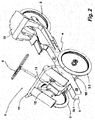
- a perspective view of the chassis of the vehicle of
figure 1 from a first point of view, - Fig. 3:
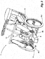
- another perspective view of the chassis of the vehicle depicted in
figure 1 from another point of view, - Fig. 4:
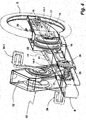
- a close-up of the power train of the vehicle of
figures 1 to 3 with the components housing the drive train being depicted in a transparent mode, and - Fig. 5:
- a perspective view showing the vehicle from its bottom side.
- A pedal propulsed land vehicle 1 designed to enhance in particular urban mobility is designed to have three wheels. In the inside side view of
figure 1 therear wheel 2 and the rightfront wheel 3 are to be seen. Thewheels chassis 4, which will be described later. Thechassis 4 is covered by a cover 5. The cover 5 is manufactured of plastic material, which may be fiber-reinforced. The cover depicted infigure 1 covers thechassis 4 as to the front, the top and the back. The right side and the left side are kept open. The front of the cover 5 is translucent. This wind shield part of the cover 5 is identified with reference numeral 6. The backside of the cover 5 incorporates a rear window. - The
chassis 4 supports a seat 7, which is depicted infigure 1 in three of its possible positions. The positions of the seat 7 alter as to their height and their position with respect to the longitudinal extension of the vehicle 1. - The two
front wheels 3 of the vehicle 1 are steered. The steering gear comprises asteering wheel 8, which is connected in a not depicted manner to a steering gear steering thefront wheels 3. - The
chassis 4 of the vehicle 1 disposes of acentral beam 9 extending in longitudinal direction from the front of the vehicle 1 to the axle of therear wheel 2. Thelongitudinal beam 9 is U- or C-shaped in cross-section, with its longitudinal opening facing groundwards. Attached to thelongitudinal beam 9 is a cross-beam 10 extending width-wise to the vehicle. The cross-beam 10 carries thefront wheels 3, 3.1 (seefigures 2, 3 ). Mounted on thecross-beam 10 is a mountingbracket 11 linking the bearings of thefront wheels 3, 3.1 over the topside of thebeam 9. - Mounted on the topside of the
beam 9 between the twofront wheels 3, 3.1 is apedal drive housing 12, also bearing apedal drive 13. - The arrangement of the
pedal drive 13 within thehousing 12 resting on the topside ofbeam 9 may better be seen infigure 3. Figure 3 also allows a better view to thecross-beam 10 and the mountingbracket 11.Fig 3 further shows that the front wheels are mounted to have a negative run-over. - The vehicle 1 has a power train to drive the
rear wheel 2, which power train is in the depicted embodiment divided into threedrive train segments 14, 14.1, 14.2. A firstdrive train segment 14 drives theaxle 15 of anelectric motor 16. Theaxle 15 of theelectric motor 16 drives therear wheel 2 via the second drive train segment 14.1. The driving means of the second drive train segment 14.1 is in the depicted embodiment achain 17 receiving its movement by rotation of theaxle 15. Therefore, thechain 17 is driven by achain wheel 18 sitting on theaxle 15. Asecond chain wheel 19 is arranged on the axle of therear wheel 2 to receive the driving force. Incorporated into the axle of therear wheel 2 is agear hub 20. The driving force received by thechain wheel 19 is transferred through thegear hub 20 and then brings therear wheel 2 into rotational movement. Thegear hub 20 may be actuated by the driver. - The first
drive train segment 14 comprises achain 21 as driving means driving achain wheel 22 also sitting on theaxle 15 of theelectric motor 16. Thechain wheel 22 is a free-wheel. Therefore, driving force may only be transferred from thechain 21 to theaxle 15 in one direction of rotation. This is the direction for propulsing the vehicle 1 into a forward movement. The firstdrive train segment 14 is itself driven by a third drive train segment 14.2, which incorporates thepedal drive 13. The driving means of the third drive train segment 14.2 again is achain 23. Thechain 23 is driven by rotating the twopedals 24, 24.1 of thepedal drive 13 around their axle and thus driving a chain wheel, which in turn drives thechain 23. As to be seen in the figures, both drivetrain segments 14, 14.2 are arranged angular to each other by arrangement of thehousing 12, enclosing the third drive train segment 14.2, angular to thebeam 9, enclosing the firstdrive train segment 14. In the embodiment disclosed bothdrive train segments 14, 14.2 enclose an obtuse angle. This arrangement allows - which might best be seen in the inside view of the vehicle 1 according tofigure 1 - to arrange the firstdrive train segment 14 within thebeam 9 rather low to the ground but still have the axis of thepedal drive 13 sufficiently high for good and efficient pedalling as well as for comfort reasons. Therefore, this arrangement allows to have an easy access into the vehicle, thus providing for an easy entering and an easing exiting of the vehicle. The step to be taken is rather low. In particular it may be noted, that inside the vehicle nothing is in the way between the seat 7 and thepedal drive 13. As further to be seen fromfigure 1 , the height of thebeam 9 is basically arranged below the axis of rotation of the twofront wheels 3, 3.1 and therear wheel 2. - In the interface between the two drive train segments 14.2 and 14, which interface is made by an
axle 25 with two chain wheels - one to receive the driving force via thechain 23 and one driving thechain 21 bringing the pedal force onto the axle 15 - coupled toaxle 25 is atension sensor 26 sensing the strain on thechain 23 driving theaxle 25. Thetension sensor 26 senses the tension applied tochain 23, which in turn is dependent on the muscular force applied to thepedal drive 13. The output of thetension sensor 26 is input into a computing device, which in turn actuates theelectric motor 16. Depending on the sensed tension of thechain 23 theelectric motor 16 is actuated to support propulsion of the vehicle 1. - The
electric motor 16 may be actuated in both directions of rotation. In case the vehicle 1 is to be propulsed in reverse motion, then theelectric motor 16 will be actuated accordingly. Reversing the vehicle 1 is with the embodiment described not possible using muscular force due to thefree wheel 22 on theaxle 15 of theelectric motor 16. According to another embodiment, thefree wheel 22, which induces the driving force of the firstdrive train segment 14 into the second drive train segment 14.1, may be arranged in such a manner that its free wheel state may be blocked. Such blocking of the free wheel state of this wheel may then be utilized to propulse the vehicle with pedal force also backwards. For the locking actuation of this wheel an electromagnetic actuating device may for example be utilized locking the free wheel state of this wheel as long as the actuating device itself is actuated. Such actuating device could be linked with a forward movement sensor, which output signals could be utilized to have this wheel be put back in its free wheel state as soon as a forward motion of the vehicle is detected. - The
longitudinal beam 9 of the depicted embodiment is a sheet-metal construction. Thelongitudinal beam 9 provides a top 27 and twoside parts 28, 28.1 (see for examplefigures 2 and5 ). In the depicted embodiment theside parts 28, 28.1 each have alower flange 29, 29.1 arranged angular in the direction of thelongitudinal opening 30 of thebeam 9. As to be seen infigure 5 , the longitudinal beam is principally of a U-shaped form in its cross-section with itslongitudinal opening 30 facing groundwards. The longitudinal opening is covered by a removable bottom plate in order to form a closed section for optimal torsional stiffness. The removable bottom plate further provides simultaneously protection of the incorporated driving elements as well as easy access for assembly and maintenance.Figure 5 shows thelongitudinal beam 9 without the attached removable bottom plate, thus allowing an insight into theopening 30. - The front part in front of the
cross-beam 10 is covered by acover 31 material. Anothercover 32 is arranged to protect theelectric motor 16 and itschain wheels axle 15. Thecover 32 is arranged pivotally with respect to thelongitudinal beam 9 for easy access to theelectric motor 16 and to dismount the whole rear structure. Thecover 32 is to be turned around a horizontal axis crossing the front ends of the sides of thecover 32. - The design of the
longitudinal beam 9 with its U-shaped cross-section gives not only the desired strength and stability to the vehicle 1 but also serves as a good support for attaching other parts of the vehicle 1 to it, such as thecross-beam 10, thepedal drive housing 12, but also the rear support 33 extending over therear wheel 2. Therear support 34 serves to attach thecover 25 and also to provide for a luggage compartment 33 behind the driver's seat 7 (seefigure 1 ). - To be seen in
figure 5 is also the arrangement of thebracket 11 linking to frontwheel support parts 35, 35.1, on which thefront wheels 3, 3.1 are borne. The frontwheel support parts 35, 35.1 are needed because of the low arrangement of thelongitudinal beam 9 and the higher position of the rotational axis of thefront wheels 3, 3.1 with respect to thecross-beam 10. Thebracket 11 not only reinforces the frontwheel support parts 35, 35.1 but also serves besides its functionality to holdbattery cases 36, 36.1 for the protection of the inside of the vehicle 1. Thebattery cases 36, 36.1 contain batteries powering theelectric motor 16. Thecross-beam 10 is also a sheet-metal construction, just like the frontwheel support parts 35, 35.1. - In particular,
figures 1 to 3 show, that thefront wheels 3, 3.1 and therear wheel 2 are of a rather small size. This not only enhances manoeverability of the vehicle 1 but also allows to have thepedal drive 13 arranged between the steered front wheels. The rather small sized wheels also support the arrangement of thelongitudinal beam 9 in a rather low position enhancing comfort and - because having the weight at a low position - a safe and good driving performance. - The front end of the vehicle 1 is designed to provide a driver protection. As such due to the construction of the vehicle 1 described above the following elements resemble a frame or cage respectively protecting the driver in a very effective manner in case of an accident. This protective cage may best seen on
figure 1 . This protective cage is made up of the front part of thelongitudinal beam 9, which as such is already protective for the driver, a frontfender connection beam 37, being attached to thelongitudinal beam 9, adashboard support plate 38 and the mountingbracket 11. With these elements a protective cage is formed enclosing thepedal drive 13 and the drivers feet and part of his legs when working on thepedal drive 13. In an embodiment not depicted in the figures the front part of the longitudinal beam - the front end, to which the fender connection beam is attached - is worked to have the additional functionality of a crash box. Such crash box functionality is used to consume the energy introduced into the vehicle 1 in case of front crash and thus reducing the impact to the driver. - The invention is described by way of one embodiment only. There are further possibilities to work the invention. It is possible for instance to use more than one longitudinal beam or to use a longitudinal beam, which already implies a ground floor of the compartment of the vehicle.
- The term U-shape referring to the cross sectional form of the at least one longitudinal beam is to be understood in a broad sense. This also implies C-shape beams and all other beams having a top and connected to the top side parts or side walls respectively enclosing a channel.
- In the embodiment disclosed with reference to the figures the longitudinal beam is a profiled sheet metal. Of course, other materials may be used for the design of this beam. For example this beam may be manufactured as a cast or extruded light weight metal work piece, for example manufactured from an aluminium alloy or a fiber reinforced material.
Reference List 1 vehicle 36, 36.1 battery case 2 rear wheel 37 fender connection beam 3, 3.1 front wheel 38 dashboard support plate 4 chassis 5 cover 6 wind shield 7 seat 8 steering wheel 9 beam 10 cross-beam 11 mounting bracket 12 pedal drive housing 13 pedal drive 14, 14.1, 14.2 drive train segment 15 axle 16 electric motor 17 chain 18 chain wheel 19 chain wheel 20 gear hub 21 chain 22 chain wheel 23 chain 24, 24.1 pedal 25 axle 26 tension sensor 27 top 28, 28.1 side part 29, 29.1 flange 30 opening 31 cover 32 cover 33 rear support 34 luggage compartment 35, 35.1 front wheel support part
Claims (16)
- Human powered land vehicle with two steered front wheels (3, 3.1) and one rear wheel (2) driven by a drive train, which drive (13) train incorporates a human powered actuator to be actuated for propulsion of the vehicle (1) by a person driving the vehicle (1) and kinematically coupled to a driven wheel for propulsing the vehicle (1) in at least one driving direction and which vehicle further disposes of a non-human powered actuator (16) arranged to drive at least one of the wheels to the vehicle (7), and with at least one longitudinal beam (9) and a cross-beam (10), whereas the rear wheel (2) is connected to the longitudinal beam (9) and the front wheels (3, 3.1) are supported by the cross-beam (10) and whereas at least part of the drive train is being housed within the longitudinal beam (9), a seat (7) is supported by the longitudinal beam (9) and is designed that the person driving the vehicle (1) is in a sitting position, characterized in that the longitudinal beam (9) is principally of a U-shaped form in its cross-section with its longitudinal opening (30) facing groundwards, in that the axis of rotation of the pedal drive (13) is arranged between the two front wheels (3, 3.1) and with distance to the top (27) of the longitudinal beam (9) and within a pedal drive housing (12) with the pedals (24, 24.1) being arranged outside this housing (12).
- Vehicle according to claim 1, characterized in that a rear wheel support is connected movable around a vertical axis to the adjacent end of the longitudinal beam, whereas the movability of the rear wheel support is limited to a few degrees in each direction departing from the neutral position, and in that the movability of the rear wheel support is linked to a steering gear steering the front wheels such that a steering action on the rear wheel support is directed in the opposite direction to the steering direction of the front wheels.
- Vehicle according to one of the claims 1 or 2, characterized in that the section of the longitudinal beam (9) between the pedal drive (13) and the seat (7) is arranged in the vertical extension of the vehicle below the axis of rotation of the front wheels (3, 3.1).
- Vehicle according to claim 3, characterized in that the sitting level of the seat (7) in any of its possible positions is arranged in the vertical extension of the vehicle (1) well above the axis of rotation of the front wheels (3, 3.1).
- Vehicle according to one of claims 1 to 4, characterized in that the housing (12) of the pedal drive (13) with its face facing the seat (7) and the top (27) of the longitudinal beam (9) enclose an obtuse angle.
- Vehicle according to one of claims 1 to 5, characterized in that the outer ends of the cross-beam (10) carry front wheel support parts (35, 35.1) extending in the vertical direction of the vehicle (1) on which parts (35, 35.1) the front wheels (3, 3.1) are mounted.
- Vehicle according to claim 6, characterized in that the front wheel support parts (35, 35.1) arranged at the ends of the cross-beam (10) are linked to each other by a bracket (11) extending over the pedal drive housing (12).
- Vehicle according to claim 7, characterized in that the bracket (11) supports one or more battery cases (36, 36.1) containing batteries to power an electric motor (16).
- Vehicle according to one of claims 1 to 8, characterized in that the electric motor (16) and the seat (7) are arranged on top of each other or at least approximately on top of each other, the seat (7) resembling the upper part of this arrangement.
- Vehicle according to claim 9, characterized in that the seat (7) and the electric motor (16) are arranged in the longitudinal extension of the vehicle (1) in front of the rear wheel (2).
- Vehicle according to claim 10, characterized in that the longitudinal beam (9) carries a rear support (33) extending over the top of the rear wheel (2) and being independent of the rear wheel support.
- Vehicle according to one of claims 1 to 11, characterized in that the vehicle comprises a cover (5).
- Vehicle according to one of claims 1 to 12, characterized in that the longitudinal opening (30) of the longitudinal beam (9) is provided with a removable bottom plate closing the longitudinal opening (30) in its mounted or closed arrangement.
- Vehicle according to one of claims 1 to 13, characterized in that a front section of the vehicle (1) is formed to provide a protective cage.
- Vehicle according to claim 14, characterized in that the protective cage is made up of the front section to the longitudinal beam (9), a fender connection beam (37) connected to the longitudinal beam (9), a dashboard support plate (38) connected to the fender connection beam (37) and connected to a bracket (11) extending in traverse direction of the vehicle (1) being with its ends in connection with the longitudinal beam (9).
- Vehicle according to 14 or 15, characterized in that the front section of the longitudinal beam is designed to dispose of the functionality of a energy absorbing crash box.
Applications Claiming Priority (1)
| Application Number | Priority Date | Filing Date | Title |
|---|---|---|---|
| PCT/EP2012/076733 WO2014094888A1 (en) | 2012-12-21 | 2012-12-21 | Human powered land vehicle |
Publications (2)
| Publication Number | Publication Date |
|---|---|
| EP2934993A1 EP2934993A1 (en) | 2015-10-28 |
| EP2934993B1 true EP2934993B1 (en) | 2016-03-16 |
Family
ID=47557102
Family Applications (1)
| Application Number | Title | Priority Date | Filing Date |
|---|---|---|---|
| EP12813862.5A Not-in-force EP2934993B1 (en) | 2012-12-21 | 2012-12-21 | Human powered land vehicle |
Country Status (2)
| Country | Link |
|---|---|
| EP (1) | EP2934993B1 (en) |
| WO (1) | WO2014094888A1 (en) |
Families Citing this family (1)
| Publication number | Priority date | Publication date | Assignee | Title |
|---|---|---|---|---|
| NO345817B1 (en) * | 2019-09-20 | 2021-08-23 | Podbike As | Device for adjusting the distance between a pedal module and a seat |
Family Cites Families (3)
| Publication number | Priority date | Publication date | Assignee | Title |
|---|---|---|---|---|
| US5069469A (en) * | 1987-06-10 | 1991-12-03 | H.P.E. Corporation | Recumbent cycle |
| DE29515188U1 (en) | 1995-09-22 | 1996-02-08 | Bühler, Uwe, 71229 Leonberg | Recumbent tricycle with additional drive |
| DE19750044A1 (en) * | 1997-11-12 | 1998-06-04 | Weber Thomas | Tricycle with electric drive motor, generator and protective cowling |
-
2012
- 2012-12-21 EP EP12813862.5A patent/EP2934993B1/en not_active Not-in-force
- 2012-12-21 WO PCT/EP2012/076733 patent/WO2014094888A1/en not_active Ceased
Also Published As
| Publication number | Publication date |
|---|---|
| EP2934993A1 (en) | 2015-10-28 |
| WO2014094888A1 (en) | 2014-06-26 |
Similar Documents
| Publication | Publication Date | Title |
|---|---|---|
| EP1530536B1 (en) | Four-wheeled vehicle | |
| US4227589A (en) | Combined engine and pedal powered vehicles | |
| US4412595A (en) | Three wheeled vehicle | |
| US7748728B2 (en) | Kid cab trike | |
| CN110914143A (en) | Electric assist bicycle | |
| CA2301006A1 (en) | Battery-powered vehicle | |
| US11932348B2 (en) | Motor assisted pedal apparatus | |
| US20150329164A1 (en) | Human Powered Land Vehicle | |
| CN1504382A (en) | Body structure of a two-wheeled motorcycle | |
| US11273879B2 (en) | Motorized towing vehicle | |
| EP2934994B1 (en) | Human powered land vehicle | |
| JP2012502843A (en) | Motorized motorcycle or tricycle for carrying people and / or luggage | |
| WO2014094888A1 (en) | Human powered land vehicle | |
| CN102001409A (en) | Electric bicycle | |
| KR200301491Y1 (en) | A cart type tricycle | |
| CN223865035U (en) | Motorcycle | |
| JP2006111103A (en) | Bicycle | |
| JPH11105768A (en) | Frame for electric bicycle | |
| CN1103841A (en) | Two/three wheeled motorcycle | |
| JP2005297643A (en) | Three-wheel type power-assisted bicycle | |
| JP3040212U (en) | A basket to reduce the running of the bicycle | |
| CN119459937A (en) | A protective travel vehicle | |
| IT201900003567A1 (en) | VEHICLE FOR THE TRANSPORT OF PEOPLE AND / OR GOODS WITH A CLOSED BODY. | |
| JP3829850B2 (en) | Auxiliary power-assisted bicycle | |
| CN121553286A (en) | Novel rear suspension structure of two-wheel vehicle |
Legal Events
| Date | Code | Title | Description |
|---|---|---|---|
| PUAI | Public reference made under article 153(3) epc to a published international application that has entered the european phase |
Free format text: ORIGINAL CODE: 0009012 |
|
| 17P | Request for examination filed |
Effective date: 20150624 |
|
| AK | Designated contracting states |
Kind code of ref document: A1 Designated state(s): AL AT BE BG CH CY CZ DE DK EE ES FI FR GB GR HR HU IE IS IT LI LT LU LV MC MK MT NL NO PL PT RO RS SE SI SK SM TR |
|
| AX | Request for extension of the european patent |
Extension state: BA ME |
|
| GRAP | Despatch of communication of intention to grant a patent |
Free format text: ORIGINAL CODE: EPIDOSNIGR1 |
|
| DAX | Request for extension of the european patent (deleted) | ||
| INTG | Intention to grant announced |
Effective date: 20151123 |
|
| GRAS | Grant fee paid |
Free format text: ORIGINAL CODE: EPIDOSNIGR3 |
|
| GRAA | (expected) grant |
Free format text: ORIGINAL CODE: 0009210 |
|
| AK | Designated contracting states |
Kind code of ref document: B1 Designated state(s): AL AT BE BG CH CY CZ DE DK EE ES FI FR GB GR HR HU IE IS IT LI LT LU LV MC MK MT NL NO PL PT RO RS SE SI SK SM TR |
|
| REG | Reference to a national code |
Ref country code: GB Ref legal event code: FG4D |
|
| REG | Reference to a national code |
Ref country code: CH Ref legal event code: EP |
|
| REG | Reference to a national code |
Ref country code: IE Ref legal event code: FG4D |
|
| REG | Reference to a national code |
Ref country code: AT Ref legal event code: REF Ref document number: 780961 Country of ref document: AT Kind code of ref document: T Effective date: 20160415 |
|
| REG | Reference to a national code |
Ref country code: DE Ref legal event code: R096 Ref document number: 602012015786 Country of ref document: DE |
|
| REG | Reference to a national code |
Ref country code: NL Ref legal event code: FP |
|
| REG | Reference to a national code |
Ref country code: LT Ref legal event code: MG4D |
|
| PG25 | Lapsed in a contracting state [announced via postgrant information from national office to epo] |
Ref country code: HR Free format text: LAPSE BECAUSE OF FAILURE TO SUBMIT A TRANSLATION OF THE DESCRIPTION OR TO PAY THE FEE WITHIN THE PRESCRIBED TIME-LIMIT Effective date: 20160316 Ref country code: GR Free format text: LAPSE BECAUSE OF FAILURE TO SUBMIT A TRANSLATION OF THE DESCRIPTION OR TO PAY THE FEE WITHIN THE PRESCRIBED TIME-LIMIT Effective date: 20160617 Ref country code: FI Free format text: LAPSE BECAUSE OF FAILURE TO SUBMIT A TRANSLATION OF THE DESCRIPTION OR TO PAY THE FEE WITHIN THE PRESCRIBED TIME-LIMIT Effective date: 20160316 Ref country code: NO Free format text: LAPSE BECAUSE OF FAILURE TO SUBMIT A TRANSLATION OF THE DESCRIPTION OR TO PAY THE FEE WITHIN THE PRESCRIBED TIME-LIMIT Effective date: 20160616 |
|
| REG | Reference to a national code |
Ref country code: AT Ref legal event code: MK05 Ref document number: 780961 Country of ref document: AT Kind code of ref document: T Effective date: 20160316 |
|
| PG25 | Lapsed in a contracting state [announced via postgrant information from national office to epo] |
Ref country code: LT Free format text: LAPSE BECAUSE OF FAILURE TO SUBMIT A TRANSLATION OF THE DESCRIPTION OR TO PAY THE FEE WITHIN THE PRESCRIBED TIME-LIMIT Effective date: 20160316 Ref country code: LV Free format text: LAPSE BECAUSE OF FAILURE TO SUBMIT A TRANSLATION OF THE DESCRIPTION OR TO PAY THE FEE WITHIN THE PRESCRIBED TIME-LIMIT Effective date: 20160316 Ref country code: SE Free format text: LAPSE BECAUSE OF FAILURE TO SUBMIT A TRANSLATION OF THE DESCRIPTION OR TO PAY THE FEE WITHIN THE PRESCRIBED TIME-LIMIT Effective date: 20160316 Ref country code: RS Free format text: LAPSE BECAUSE OF FAILURE TO SUBMIT A TRANSLATION OF THE DESCRIPTION OR TO PAY THE FEE WITHIN THE PRESCRIBED TIME-LIMIT Effective date: 20160316 |
|
| PG25 | Lapsed in a contracting state [announced via postgrant information from national office to epo] |
Ref country code: PL Free format text: LAPSE BECAUSE OF FAILURE TO SUBMIT A TRANSLATION OF THE DESCRIPTION OR TO PAY THE FEE WITHIN THE PRESCRIBED TIME-LIMIT Effective date: 20160316 Ref country code: EE Free format text: LAPSE BECAUSE OF FAILURE TO SUBMIT A TRANSLATION OF THE DESCRIPTION OR TO PAY THE FEE WITHIN THE PRESCRIBED TIME-LIMIT Effective date: 20160316 Ref country code: IS Free format text: LAPSE BECAUSE OF FAILURE TO SUBMIT A TRANSLATION OF THE DESCRIPTION OR TO PAY THE FEE WITHIN THE PRESCRIBED TIME-LIMIT Effective date: 20160716 |
|
| PG25 | Lapsed in a contracting state [announced via postgrant information from national office to epo] |
Ref country code: ES Free format text: LAPSE BECAUSE OF FAILURE TO SUBMIT A TRANSLATION OF THE DESCRIPTION OR TO PAY THE FEE WITHIN THE PRESCRIBED TIME-LIMIT Effective date: 20160316 Ref country code: PT Free format text: LAPSE BECAUSE OF FAILURE TO SUBMIT A TRANSLATION OF THE DESCRIPTION OR TO PAY THE FEE WITHIN THE PRESCRIBED TIME-LIMIT Effective date: 20160718 Ref country code: AT Free format text: LAPSE BECAUSE OF FAILURE TO SUBMIT A TRANSLATION OF THE DESCRIPTION OR TO PAY THE FEE WITHIN THE PRESCRIBED TIME-LIMIT Effective date: 20160316 Ref country code: SM Free format text: LAPSE BECAUSE OF FAILURE TO SUBMIT A TRANSLATION OF THE DESCRIPTION OR TO PAY THE FEE WITHIN THE PRESCRIBED TIME-LIMIT Effective date: 20160316 Ref country code: RO Free format text: LAPSE BECAUSE OF FAILURE TO SUBMIT A TRANSLATION OF THE DESCRIPTION OR TO PAY THE FEE WITHIN THE PRESCRIBED TIME-LIMIT Effective date: 20160316 Ref country code: SK Free format text: LAPSE BECAUSE OF FAILURE TO SUBMIT A TRANSLATION OF THE DESCRIPTION OR TO PAY THE FEE WITHIN THE PRESCRIBED TIME-LIMIT Effective date: 20160316 Ref country code: CZ Free format text: LAPSE BECAUSE OF FAILURE TO SUBMIT A TRANSLATION OF THE DESCRIPTION OR TO PAY THE FEE WITHIN THE PRESCRIBED TIME-LIMIT Effective date: 20160316 |
|
| REG | Reference to a national code |
Ref country code: DE Ref legal event code: R097 Ref document number: 602012015786 Country of ref document: DE |
|
| REG | Reference to a national code |
Ref country code: FR Ref legal event code: PLFP Year of fee payment: 5 |
|
| PG25 | Lapsed in a contracting state [announced via postgrant information from national office to epo] |
Ref country code: IT Free format text: LAPSE BECAUSE OF FAILURE TO SUBMIT A TRANSLATION OF THE DESCRIPTION OR TO PAY THE FEE WITHIN THE PRESCRIBED TIME-LIMIT Effective date: 20160316 |
|
| PLBE | No opposition filed within time limit |
Free format text: ORIGINAL CODE: 0009261 |
|
| STAA | Information on the status of an ep patent application or granted ep patent |
Free format text: STATUS: NO OPPOSITION FILED WITHIN TIME LIMIT |
|
| PG25 | Lapsed in a contracting state [announced via postgrant information from national office to epo] |
Ref country code: DK Free format text: LAPSE BECAUSE OF FAILURE TO SUBMIT A TRANSLATION OF THE DESCRIPTION OR TO PAY THE FEE WITHIN THE PRESCRIBED TIME-LIMIT Effective date: 20160316 |
|
| PGFP | Annual fee paid to national office [announced via postgrant information from national office to epo] |
Ref country code: NL Payment date: 20161221 Year of fee payment: 5 Ref country code: GB Payment date: 20161222 Year of fee payment: 5 Ref country code: DE Payment date: 20161213 Year of fee payment: 5 |
|
| 26N | No opposition filed |
Effective date: 20161219 |
|
| PG25 | Lapsed in a contracting state [announced via postgrant information from national office to epo] |
Ref country code: BG Free format text: LAPSE BECAUSE OF FAILURE TO SUBMIT A TRANSLATION OF THE DESCRIPTION OR TO PAY THE FEE WITHIN THE PRESCRIBED TIME-LIMIT Effective date: 20160616 |
|
| PGFP | Annual fee paid to national office [announced via postgrant information from national office to epo] |
Ref country code: FR Payment date: 20161222 Year of fee payment: 5 Ref country code: BE Payment date: 20161221 Year of fee payment: 5 |
|
| PG25 | Lapsed in a contracting state [announced via postgrant information from national office to epo] |
Ref country code: SI Free format text: LAPSE BECAUSE OF FAILURE TO SUBMIT A TRANSLATION OF THE DESCRIPTION OR TO PAY THE FEE WITHIN THE PRESCRIBED TIME-LIMIT Effective date: 20160316 |
|
| REG | Reference to a national code |
Ref country code: CH Ref legal event code: PL |
|
| PG25 | Lapsed in a contracting state [announced via postgrant information from national office to epo] |
Ref country code: MC Free format text: LAPSE BECAUSE OF FAILURE TO SUBMIT A TRANSLATION OF THE DESCRIPTION OR TO PAY THE FEE WITHIN THE PRESCRIBED TIME-LIMIT Effective date: 20160316 |
|
| REG | Reference to a national code |
Ref country code: IE Ref legal event code: MM4A |
|
| PG25 | Lapsed in a contracting state [announced via postgrant information from national office to epo] |
Ref country code: LI Free format text: LAPSE BECAUSE OF NON-PAYMENT OF DUE FEES Effective date: 20161231 Ref country code: CH Free format text: LAPSE BECAUSE OF NON-PAYMENT OF DUE FEES Effective date: 20161231 Ref country code: LU Free format text: LAPSE BECAUSE OF NON-PAYMENT OF DUE FEES Effective date: 20161221 |
|
| PG25 | Lapsed in a contracting state [announced via postgrant information from national office to epo] |
Ref country code: IE Free format text: LAPSE BECAUSE OF NON-PAYMENT OF DUE FEES Effective date: 20161221 |
|
| PG25 | Lapsed in a contracting state [announced via postgrant information from national office to epo] |
Ref country code: HU Free format text: LAPSE BECAUSE OF FAILURE TO SUBMIT A TRANSLATION OF THE DESCRIPTION OR TO PAY THE FEE WITHIN THE PRESCRIBED TIME-LIMIT; INVALID AB INITIO Effective date: 20121221 |
|
| PG25 | Lapsed in a contracting state [announced via postgrant information from national office to epo] |
Ref country code: CY Free format text: LAPSE BECAUSE OF FAILURE TO SUBMIT A TRANSLATION OF THE DESCRIPTION OR TO PAY THE FEE WITHIN THE PRESCRIBED TIME-LIMIT Effective date: 20160316 Ref country code: MK Free format text: LAPSE BECAUSE OF FAILURE TO SUBMIT A TRANSLATION OF THE DESCRIPTION OR TO PAY THE FEE WITHIN THE PRESCRIBED TIME-LIMIT Effective date: 20160316 |
|
| REG | Reference to a national code |
Ref country code: DE Ref legal event code: R119 Ref document number: 602012015786 Country of ref document: DE |
|
| REG | Reference to a national code |
Ref country code: NL Ref legal event code: MM Effective date: 20180101 |
|
| GBPC | Gb: european patent ceased through non-payment of renewal fee |
Effective date: 20171221 |
|
| PG25 | Lapsed in a contracting state [announced via postgrant information from national office to epo] |
Ref country code: MT Free format text: LAPSE BECAUSE OF NON-PAYMENT OF DUE FEES Effective date: 20161221 Ref country code: NL Free format text: LAPSE BECAUSE OF NON-PAYMENT OF DUE FEES Effective date: 20180101 |
|
| REG | Reference to a national code |
Ref country code: FR Ref legal event code: ST Effective date: 20180831 |
|
| REG | Reference to a national code |
Ref country code: BE Ref legal event code: FP Effective date: 20160610 Ref country code: BE Ref legal event code: MM Effective date: 20171231 |
|
| PG25 | Lapsed in a contracting state [announced via postgrant information from national office to epo] |
Ref country code: TR Free format text: LAPSE BECAUSE OF FAILURE TO SUBMIT A TRANSLATION OF THE DESCRIPTION OR TO PAY THE FEE WITHIN THE PRESCRIBED TIME-LIMIT Effective date: 20160316 Ref country code: DE Free format text: LAPSE BECAUSE OF NON-PAYMENT OF DUE FEES Effective date: 20180703 Ref country code: FR Free format text: LAPSE BECAUSE OF NON-PAYMENT OF DUE FEES Effective date: 20180102 Ref country code: AL Free format text: LAPSE BECAUSE OF FAILURE TO SUBMIT A TRANSLATION OF THE DESCRIPTION OR TO PAY THE FEE WITHIN THE PRESCRIBED TIME-LIMIT Effective date: 20160316 |
|
| PG25 | Lapsed in a contracting state [announced via postgrant information from national office to epo] |
Ref country code: GB Free format text: LAPSE BECAUSE OF NON-PAYMENT OF DUE FEES Effective date: 20171221 Ref country code: BE Free format text: LAPSE BECAUSE OF NON-PAYMENT OF DUE FEES Effective date: 20171231 |