EP2934381B1 - Intraocular lens storage system - Google Patents
Intraocular lens storage system Download PDFInfo
- Publication number
- EP2934381B1 EP2934381B1 EP13805865.6A EP13805865A EP2934381B1 EP 2934381 B1 EP2934381 B1 EP 2934381B1 EP 13805865 A EP13805865 A EP 13805865A EP 2934381 B1 EP2934381 B1 EP 2934381B1
- Authority
- EP
- European Patent Office
- Prior art keywords
- intraocular lens
- injection device
- transfer
- storage container
- storage system
- Prior art date
- Legal status (The legal status is an assumption and is not a legal conclusion. Google has not performed a legal analysis and makes no representation as to the accuracy of the status listed.)
- Active
Links
- 238000002347 injection Methods 0.000 claims description 103
- 239000007924 injection Substances 0.000 claims description 103
- 238000002513 implantation Methods 0.000 claims description 3
- 238000000034 method Methods 0.000 claims description 3
- 238000003780 insertion Methods 0.000 description 40
- 230000037431 insertion Effects 0.000 description 40
- 230000008878 coupling Effects 0.000 description 5
- 238000010168 coupling process Methods 0.000 description 5
- 238000005859 coupling reaction Methods 0.000 description 5
- 230000000903 blocking effect Effects 0.000 description 3
- 239000000463 material Substances 0.000 description 3
- 238000009516 primary packaging Methods 0.000 description 3
- 239000000654 additive Substances 0.000 description 2
- 230000003287 optical effect Effects 0.000 description 2
- 239000004743 Polypropylene Substances 0.000 description 1
- 238000005452 bending Methods 0.000 description 1
- 238000002716 delivery method Methods 0.000 description 1
- 230000001419 dependent effect Effects 0.000 description 1
- 238000006073 displacement reaction Methods 0.000 description 1
- 230000000149 penetrating effect Effects 0.000 description 1
- -1 polypropylene Polymers 0.000 description 1
- 229920001155 polypropylene Polymers 0.000 description 1
- 238000004321 preservation Methods 0.000 description 1
- 239000012858 resilient material Substances 0.000 description 1
- 238000009517 secondary packaging Methods 0.000 description 1
- 230000001954 sterilising effect Effects 0.000 description 1
- 238000004659 sterilization and disinfection Methods 0.000 description 1
- 229920001169 thermoplastic Polymers 0.000 description 1
- 239000004416 thermosoftening plastic Substances 0.000 description 1
Images


Classifications
-
- A—HUMAN NECESSITIES
- A61—MEDICAL OR VETERINARY SCIENCE; HYGIENE
- A61F—FILTERS IMPLANTABLE INTO BLOOD VESSELS; PROSTHESES; DEVICES PROVIDING PATENCY TO, OR PREVENTING COLLAPSING OF, TUBULAR STRUCTURES OF THE BODY, e.g. STENTS; ORTHOPAEDIC, NURSING OR CONTRACEPTIVE DEVICES; FOMENTATION; TREATMENT OR PROTECTION OF EYES OR EARS; BANDAGES, DRESSINGS OR ABSORBENT PADS; FIRST-AID KITS
- A61F2/00—Filters implantable into blood vessels; Prostheses, i.e. artificial substitutes or replacements for parts of the body; Appliances for connecting them with the body; Devices providing patency to, or preventing collapsing of, tubular structures of the body, e.g. stents
- A61F2/02—Prostheses implantable into the body
- A61F2/14—Eye parts, e.g. lenses, corneal implants; Implanting instruments specially adapted therefor; Artificial eyes
- A61F2/16—Intraocular lenses
- A61F2/1662—Instruments for inserting intraocular lenses into the eye
- A61F2/167—Instruments for inserting intraocular lenses into the eye with pushable plungers
-
- A—HUMAN NECESSITIES
- A61—MEDICAL OR VETERINARY SCIENCE; HYGIENE
- A61F—FILTERS IMPLANTABLE INTO BLOOD VESSELS; PROSTHESES; DEVICES PROVIDING PATENCY TO, OR PREVENTING COLLAPSING OF, TUBULAR STRUCTURES OF THE BODY, e.g. STENTS; ORTHOPAEDIC, NURSING OR CONTRACEPTIVE DEVICES; FOMENTATION; TREATMENT OR PROTECTION OF EYES OR EARS; BANDAGES, DRESSINGS OR ABSORBENT PADS; FIRST-AID KITS
- A61F2/00—Filters implantable into blood vessels; Prostheses, i.e. artificial substitutes or replacements for parts of the body; Appliances for connecting them with the body; Devices providing patency to, or preventing collapsing of, tubular structures of the body, e.g. stents
- A61F2/02—Prostheses implantable into the body
- A61F2/14—Eye parts, e.g. lenses, corneal implants; Implanting instruments specially adapted therefor; Artificial eyes
- A61F2/16—Intraocular lenses
- A61F2/1662—Instruments for inserting intraocular lenses into the eye
- A61F2/1678—Instruments for inserting intraocular lenses into the eye with a separate cartridge or other lens setting part for storage of a lens, e.g. preloadable for shipping
-
- A—HUMAN NECESSITIES
- A61—MEDICAL OR VETERINARY SCIENCE; HYGIENE
- A61F—FILTERS IMPLANTABLE INTO BLOOD VESSELS; PROSTHESES; DEVICES PROVIDING PATENCY TO, OR PREVENTING COLLAPSING OF, TUBULAR STRUCTURES OF THE BODY, e.g. STENTS; ORTHOPAEDIC, NURSING OR CONTRACEPTIVE DEVICES; FOMENTATION; TREATMENT OR PROTECTION OF EYES OR EARS; BANDAGES, DRESSINGS OR ABSORBENT PADS; FIRST-AID KITS
- A61F2/00—Filters implantable into blood vessels; Prostheses, i.e. artificial substitutes or replacements for parts of the body; Appliances for connecting them with the body; Devices providing patency to, or preventing collapsing of, tubular structures of the body, e.g. stents
- A61F2/02—Prostheses implantable into the body
- A61F2/14—Eye parts, e.g. lenses, corneal implants; Implanting instruments specially adapted therefor; Artificial eyes
- A61F2/16—Intraocular lenses
- A61F2/1691—Packages or dispensers for intraocular lenses
Definitions
- the invention also relates to an intraocular lens transfer device for transferring an intraocular lens to an injection device with a corresponding intraocular lens storage system.
- the invention also relates to a method of transferring an intraocular lens to an injection device to provide a corresponding intraocular lens storage system.
- Intraocular lenses which are artificial eye lenses, are stored in a sterile condition until they are used or implanted. It is known to use for so-called primary packaging, which in turn are in a secondary packaging, such as a sterile bag. Fixed or loose intraocular lens receptacles for receiving the intraocular lenses may be arranged in the primary packaging. Furthermore, it is known to carry out the primary packaging itself or the intraocular lens receptacle as part of an injection device or as a complete injection device, so that the intraocular lens without manipulation, eg with tweezers, can be implanted directly through the injection device ,
- a disadvantage of these known intraocular lens storage systems is that often biocompatibility problems occur. These are mainly due to the use of lubricious additives, which can come during the sterilization and / or preservation of the intraocular lenses in contact with them.
- the slip additives are generally included in the materials used which have slip properties.
- a generic intraocular lens storage system is known from EP 2 286 764 A1 which also discloses an intraocular lens transfer assembly and method for transferring an intraocular lens to an injection device.
- the DE 10 2006 000 929 A1 also discloses a known intraocular lens storage system.
- the essence of the invention lies in the fact that the intraocular lens to be implanted is first arranged outside the injection device and, for example, in the case of planned implantation directly from the storage container to the injection device by the actuatable transfer device is transferred or transferred.
- the intraocular lens can be transferred directly from the storage container to the injection device by the actuatable transfer device or transferable.
- the intraocular lens is safe and sterile storable in the storage container.
- the injection device is at least partially insertable into the interior of the storage container.
- An injector passage opening, an injector positioning insertion port, and an injector positioning advancement port are spaced apart from each other around the injector main insertion port and extend laterally from and radially away from the injector main insertion port, respectively , It is advantageous if the guide vanes are firmly connected to an injection cartridge of the injection device. It is advantageous if the intraocular lens storage system is made of at least one thermoplastic such as polypropylene.
- the intraocular lens storage position and the intraocular lens transfer position are each end positions of the transfer device.
- the intraocular lens storage position and the intraocular lens transfer position are different, that is, spatially spaced from each other.
- a continuous movement of the transfer device between the positions is possible. It is advantageous if the movement of the transfer device is guided and a corresponding storage is provided.
- the injection device is preferably designed as an injector.
- the intraocular lens comprises an optical part and at least one haptic arranged on the optical part.
- the intraocular lens is safe in the intraocular lens recording, but deliverable, recorded or held.
- the intraocular lens in the intraocular lens receptacle is positively held, more preferably by plug-in connection, latching connection, snap connection or the like.
- the at least one actuating means according to claim 2 is preferably formed as a push button, sliding element, pulling element, release element for releasing a stored force, pivoting element, pawl element, electrical switching element or the like.
- the embodiment according to claim 3 leads to a particularly simple trained and easy to handle transfer device. It is advantageous if the at least one actuating means is designed as an attack element for interacting with the injection device when introduced into the storage container or as a lever arm. Preferably, an actuating projection on the injection device presses on the actuating means so that the transfer device is pivoted about a bearing axis in its intraocular lens transfer position.
- the transfer device is pivotally mounted on the storage container.
- Corresponding bearing elements are preferably provided or arranged on the storage container for this purpose.
- the transfer device is slidably mounted on the storage container.
- the at least one return spring means according to claim 5 is preferably formed as a spring element or spring material block. It is advantageous if the spring element is a leaf-spring element, a helical spring, a spiral spring, a torsion spring or the like. It is useful if the leaf-spring element is biased or spans at a bend. Conveniently, the spring block of material is formed of a resilient material which automatically returns to its initial state after loading.
- the injection device insertion stop according to claim 6 is preferably arranged on the storage container or the transfer device.
- the injection device insertion stop cooperates with a corresponding counter-stop on the injection device with appropriate introduction of the injection device in the storage container together. It is advantageous if the injection device insertion stop is formed by the intraocular lens itself or the intraocular lens receptacle and the counter stop is formed by an injection cartridge of the injection device.
- the at least one pivoting linkage according to claim 7 forces a pivoting movement of the at least partially introduced injection device about its longitudinal axis for the transfer and reception of the intraocular lens.
- a transfer of the intraocular lens is preferably only possible when the injection device is in its pivoted position.
- the at least one pivoting backdrop preferably cooperates with a corresponding counter-surface on the injection device during insertion.
- the storage container comprises a storage container base body and a separate closure device, wherein the injection device main insertion opening is formed in the closure device.
- the storage container thus has a storage container base body and a closure device which is formed separately and preferably also removable again from the storage container base body.
- the storage box body and the closure device are integral and inseparable from each other.
- the storage container base body and the closure device are firmly connected to each other, preferably locked together.
- the dependent claims 2 to 9 may also be the subject of independent claim 13.
- An intraocular lens storage system comprises a storage container 1 and a transfer device 2 arranged in the storage container 1, between an intraocular lens storage position and an intraocular lens transfer position remote from the intraocular lens storage position by manual operation is mobile.
- an intraocular lens (not shown) is securely and stably stored in the storage container 1, while in the intraocular lens transfer position, transfer of the intraocular lens to an injection device 3 is possible.
- an injection device 3 By means of the injection device 3, an implantation of the intraocular lens in the eye of a patient is possible.
- the storage container 1 comprises a storage container base 4 and a closure device 5, which in the assembled State fixed, but preferably releasable again, are interconnected.
- the storage container base body 4 has an outer wall 6.
- the wall 6 defines a receiving opening 7, so that there the storage container base body 4 is open to the outside.
- the storage container base 4 has a first portion 8, which adjoins the receiving opening 7 and is bounded by the wall 6 to the outside.
- a second part section 9 of the storage container base body 4 adjoins the first part section 8, which is tapered relative to the first part section 8 and is bounded by the wall 6 to the outside.
- the storage container base body 4 is delimited laterally outwardly by a side wall 10, which extends substantially perpendicular to an end-side, flange-side web 11.
- the side land 11 extends substantially in one plane. In this plane is also the receiving opening. 7
- the side wall 10 is adjoined by a main bottom 12, which is arranged opposite to the receiving opening 7 and preferably extends obliquely in sections to the side wall 10.
- a closed-end recess piece 13 connects, which is designed substantially tubular.
- the recess piece 13 extends perpendicular to the plane in which the receiving opening 7 is located.
- the recess piece 13 has a cross-sectional area that is smaller, preferably substantially smaller than the area of the Recording opening 7 is.
- the recess piece 13 is bounded by a recess web wall 22.
- the transfer device 2 is in one piece. It has a bearing piece 14, which is elongate and is formed in cross-section substantially circular or circular. With the bearing piece 14, a coupling projection 16 is fixedly connected peripherally, from which in turn a return spring means 17 extends laterally. The return spring means 17 extends at a distance from the bearing piece 14 of the coupling lug 16 and is originally angled several times. It is elongated and strip-like.
- an intraocular lens receiving body 18 is peripherally fixedly connected to the bearing piece 14.
- the intraocular lens receiving body 18 has a free abutment surface or edge 19 which preferably extends substantially tangentially to the bearing piece 14.
- Opposite to the abutment surface 19 of the intraocular lens receiving body 18 has an intraocular lens receptacle 20 which is arranged in the vertical direction spaced from the abutment surface 19.
- the bearing piece 14 is pivotally supported in at least one bearing retainer (not shown) which is mounted adjacent the recess piece 13 on the main floor 12 and allows pivoting of the transfer device 2 about a bearing axis 15 ,
- the transfer device 2 is designed like a rocker.
- the return spring means 17 is supported on the storage container 1, more precisely in the first part section 8, inside. It is advantageous if a region 21 of the return spring means 17 is spatially fixed to the storage container 1.
- the wall 6 is formed by the side wall 10, the main bottom 12 and the recess web wall 22. In the receiving opening 7, the closure device 5 is inserted positively in the mounted state of the intraocular lens storage system.
- the closure device 5 is lid-like and has a lid portion 23, which is in the inserted state of the closure device 5 approximately in the plane of the side land 11 and substantially closes the receiving opening 7. Furthermore, the closure device 5 has a side web 24, which extends approximately perpendicular to the lid portion 23 and the inside at least partially rests against the side wall 10. At the side web 24, at least one first latching means 25 is arranged on the outside, which interacts latching in the inserted state of the closure device 5 with a corresponding counter-latching means 26 on the side wall 10 latching.
- an injection device main insertion opening 27 which is aligned with the recess piece 13 and completely penetrates the lid portion 23.
- a positioning insertion opening 28 extends laterally, which completely penetrates the cover section 23 and tapers from the outside in the direction of the main floor 12 of the storage container base 4.
- the positioning insertion opening 28 is thus laterally delimited by two opposing side walls 29, which are arranged on the lid portion 23 and converge from the outside in the direction of the main bottom 12.
- a land projection 30 laterally protruding into the injection device main insertion opening 27.
- the injector main insertion opening 27 is adjoined laterally by a positioning feed opening 31 laterally spaced from the positioning insertion opening 28 in the lid section 23 and completely penetrating the lid section 23.
- the positioning feed-out opening 31 is laterally delimited by two opposing side walls 32. The side walls 32 delimiting the positioning lead-out opening 31 are substantially parallel to each other.
- a land projection 33 is provided in the region of the injection device main insertion port 27 on the lid portion 23, which defines the passage Connection between the positioning-out opening 31 and the injector main insertion opening 27 is reduced.
- a blocking projection 34 projects laterally from the side wall 32 remote from the positioning insertion opening 28 toward the opposite side wall 32.
- the blocking projection 34 is flush with the lid portion 23 on the outside, but has a smaller thickness than the lid portion 23.
- a passage opening 35 connects laterally to the injector main insertion port 27.
- the passage opening 35 is formed in the lid portion 23 and penetrates it completely.
- the positioning lead-out opening 31 is disposed between the through-hole 35 and the positioning insertion hole 28.
- the passage opening 35 is bounded laterally by two opposite side walls 36, which run parallel to each other.
- the injection device main insertion opening 27 is further adjoined laterally by a limiting opening 45, which is disposed adjacent to the positioning insertion opening 28 in the lid section 23.
- the restriction opening 45 is disposed between the positioning insertion port 28 and the passage opening 35.
- the web projection 30 faces the limiting opening 45.
- the blocking projection 34 essentially jumps away from the passage opening 35.
- the intraocular lens stored in the intraocular lens storage system is implantable by the injection device 3 into the eye of a patient.
- the injection device 3 is designed as an injector and has an elongated, tubular housing 37 and a longitudinal center axis 38.
- the injection device 3 also has at a first end 39 of the housing 37 to a holding or support projection 40 which projects radially with respect to the longitudinal center axis 38. Further, the injection device 3 has a second end 41. Adjacent to the second end 41, an externally tapered taper body 42 is inserted into the housing 37, which is hollow.
- the injection device 3 also has a loading chamber 43, which is at least partially open at the side and is arranged adjacent to the second end 41. Furthermore, the injection device 3 comprises an injection cartridge 47, which is arranged in the loading chamber 43.
- a longitudinal guide web 44 is arranged laterally on the housing 37.
- an actuating piston (not shown) in the direction of the second end 41 slidably guided.
- the actuating piston is fixedly connected to a piston rod (not shown) which axially penetrates the housing 37 and projects outwardly from the first end 39.
- the actuating piston is actuatable by the piston rod.
- the injection cartridge 47 is essentially formed by a pipe piece 49 which extends in an insertion direction of the injection device 3.
- the pipe section 49 bounded laterally outside an intraocular lens receiving space 50. It has a jacket which is separated or interrupted in the longitudinal direction of the pipe section 49, so that the pipe section 49 is there hinged or collapsible.
- the tubular piece 49 thus has two longitudinal flap areas with free end edges 51 and 52, respectively, due to the longitudinal interruption.
- the end edges 51, 52 are substantially adjacent to each other and substantially face each other.
- the pipe section 49 is substantially circular in cross section.
- the pipe section 49 is designed as a folding piece.
- the injection cartridge 47 also has a first guide vane 53 and a second guide vane (not shown) that are substantially plate-like and extend laterally outward or in the radial direction of the longitudinal center axis 38. At each flap region, a guide vane 53 is disposed on the tube piece 49. The connection areas of the guide vanes 53 run parallel to the end edges 51, 52 and preferably also adjacent to these.
- the intraocular lens storage system and the injection device 3 together form an intraocular lens transfer device.
- the closure device 5 is inserted into the receiving opening 7 and is latched there to the storage container base body 4.
- the transfer device 2 is in its original intraocular lens storage position. This is the investment area 19 inside on the main floor 12 at. In the intraocular lens receptacle 20, an intraocular lens is received.
- the injection device 3 is already partially inserted into the storage container 1.
- the injection device 3 penetrates with its main body, the injection device main insertion opening 27 and projects with its taper body 42 in the recess piece 13.
- the injection cartridge 47 is located in the first part section 8 of the storage container 1.
- the injection device 3 is in its initial position.
- the intraocular lens transfer arrangement can thus be preset or pre-assembled in this state or created by corresponding insertion of the injection device 3.
- the guide web 44 passes through the limiting opening 45.
- An actuating projection 46 which is arranged on the injection device 3 and protrudes laterally from it, bears against the coupling projection 16 at the top.
- the injection device 3 is further inserted into the storage container 1 along the longitudinal center axis 38 in an insertion direction by applying a corresponding insertion force.
- the actuating projection 46 presses on the coupling lug 16 so that the transfer device 2 is pivoted about the bearing axis 15 into its intraocular lens transfer position.
- the contact surface 19 is lifted off the main floor 12.
- the bearing axis 15 is perpendicular to the insertion direction.
- the coupling projection 16 thus forms an actuating means for actuating the transfer device 2.
- the transfer device 2 is pivoted by about 15 ° to 90 °, more preferably by about 40 ° to 75 °.
- the intraocular lens receptacle 20 is in the injection cartridge 47 or adjacent to this. More specifically, the intraocular lens is in the intraocular lens transfer position in the transfer device 2 immediately before the intraocular lens accommodating space 50.
- the elongated return spring means 17 is bent and cocked. It thus creates a return force.
- a further axial insertion of the injection device 3 is prevented by a stop of the intraocular lens on the pipe section 49.
- the first guide wing 53 passes through the passage opening 35. It is arranged between the two side walls 36, which pivot the injection cartridge 47 about the longitudinal center axis 38 by abutment against the first guide wing 53 prevent.
- the two guide vanes 53 penetrate the positioning insertion opening 28.
- the two guide vanes 53 are correspondingly for unfolding through the openings 28, 35 to unfold by bending the pipe section 49 or to pivot apart, so that an introduction of the guide vanes 53 through the openings 28, 35 is possible.
- the injection device 3 is then manually pivoted about the longitudinal center axis 38 relative to the storage container 1.
- the intraocular lens holder 20 rotates completely laterally into the injection cartridge 47 of the injection device 3.
- the intraocular lens is forced out of the intraocular lens receptacle 20, more preferably pressed, and transferred to the injection device 3 or its injection cartridge 47.
- the end edges 51, 52 are further moved towards each other, so that the intraocular lens accommodating space 50 is further closed. Embrace it the flap areas the intraocular lens.
- This pivoting movement is given by the side walls 29 of the positioning insertion opening 28 and the side walls 32 of the positioning-out opening 31, which form pivoting scenes. Too much pivoting in this direction is prevented by contact of the guide web 44 with the web projection 30. An opposite pivoting is prevented by the contact of a contact surface 54 with the web projection 30. The contact surface 54 limits the limiting opening 45 laterally. It is provided at the end of the limiting opening 45 remote from the positioning insertion opening 28. The guide web 44 then abuts against the web projection 30, so that further pivoting of the injection device 3 with respect to the storage container 1 is prevented. The web-projection 30 thus forms a pivot stop.
- the intraocular lens Upon return movement of the transfer device 2 to the intraocular lens storage position, the intraocular lens is released through the flap regions from the transfer device 2 and transferred to the intraocular lens receiving space 50.
- the second guide vane inserted through the positioning insertion port 28 is in a second pivoted position so as to be aligned with the positioning discharge port 31.
- the injection device 3 is again removed from the storage container 1 counter to the insertion direction (FIG. Fig. 11 . 12 ).
- the intraocular lens is now in the injection device 3.
- the transfer device. 2 pivoted back to its intraocular lens storage position about the bearing axis 15.
- the second guide wing passes through the positioning-discharge opening 31.
- the first guide wing 53 again passes through the passage opening 35th
- the intraocular lens can now be implanted with the injection device 3 in the eye of a patient.
Landscapes
- Health & Medical Sciences (AREA)
- Ophthalmology & Optometry (AREA)
- Cardiology (AREA)
- Oral & Maxillofacial Surgery (AREA)
- Transplantation (AREA)
- Engineering & Computer Science (AREA)
- Biomedical Technology (AREA)
- Heart & Thoracic Surgery (AREA)
- Vascular Medicine (AREA)
- Life Sciences & Earth Sciences (AREA)
- Animal Behavior & Ethology (AREA)
- General Health & Medical Sciences (AREA)
- Public Health (AREA)
- Veterinary Medicine (AREA)
- Prostheses (AREA)
Description
Die Erfindung betrifft ein Intraokularlinsen-Aufbewahrungssystem zur Aufbewahrung einer Intraokularlinse gemäß dem Oberbegriff des Anspruchs 1. Ferner richtet sich die Erfindung auch auf eine Intraokularlinsen-Übergabe-Anordnung zur Übergabe einer Intraokularlinse an eine Injektions-Einrichtung mit einem entsprechenden Intraokularlinsen-Aufbewahrungssystem. Die Erfindung betrifft außerdem ein Verfahren zur Übergabe einer Intraokularlinse an eine Injektions-Einrichtung unter Bereitstellung eines entsprechenden Intraokularlinsen-Aufbewahrungssystems.The invention also relates to an intraocular lens transfer device for transferring an intraocular lens to an injection device with a corresponding intraocular lens storage system. The invention also relates to a method of transferring an intraocular lens to an injection device to provide a corresponding intraocular lens storage system.
Intraokularlinsen, die künstliche Augenlinsen sind, werden bis zu ihrer Verwendung bzw. Implantation im sterilen Zustand gelagert. Es ist bekannt, dafür sogenannte Primär-Verpackungen heranzuziehen, die sich wiederum in einer Sekundär-Verpackung, wie einer Steril-Tüte, befinden. In den Primär-Verpackungen können fixierte oder lose Intraokularlinsen-Aufnahmen zur Aufnahme der Intraokularlinsen angeordnet sein. Weiterhin ist es bekannt, die Primär-Verpackung selbst oder die Intraokularlinsen-Aufnahme als Teil einer Injektions-Einrichtung oder als komplette Injektions-Einrichtung auszuführen, so dass die Intraokularlinse ohne Manipulation, z.B. mit einer Pinzette, direkt durch die Injektions-Einrichtung implantiert werden kann.Intraocular lenses, which are artificial eye lenses, are stored in a sterile condition until they are used or implanted. It is known to use for so-called primary packaging, which in turn are in a secondary packaging, such as a sterile bag. Fixed or loose intraocular lens receptacles for receiving the intraocular lenses may be arranged in the primary packaging. Furthermore, it is known to carry out the primary packaging itself or the intraocular lens receptacle as part of an injection device or as a complete injection device, so that the intraocular lens without manipulation, eg with tweezers, can be implanted directly through the injection device ,
Nachteilig an diesen bekannten Intraokularlinsen-Aufbewahrungssystemen ist, dass häufig Biokompatibilitäts-Probleme auftreten. Diese sind vor allem auf den Einsatz von Gleit-Additiven zurückzuführen, die während der Sterilisation und/oder Aufbewahrung der Intraokularlinsen in Kontakt mit diesen treten können. Die Gleit-Additive sind im Allgemeinen in den verwendeten Materialien enthalten, die Gleit-Eigenschaften haben.A disadvantage of these known intraocular lens storage systems is that often biocompatibility problems occur. These are mainly due to the use of lubricious additives, which can come during the sterilization and / or preservation of the intraocular lenses in contact with them. The slip additives are generally included in the materials used which have slip properties.
Ein gattungsgemäßes Intraokularlinsen-Aufbewahrungssystem ist aus der
Die
Der Erfindung liegt daher die Aufgabe zugrunde, ein Intraokularlinsen-Aufbewahrungssystem zu schaffen, bei dem Biokompatibilitäts-Probleme im Wesentlichen ausschließbar sind. Ferner soll eine Intraokularlinsen-Übergabe-Anordnung bereitgestellt werden, bei der Biokompatibilitäts-Probleme im Wesentlichen ausschließbar sind. Es soll außerdem ein entsprechendes Intraokularlinsen-Übergabe-Verfahren geliefert werden, bei dem Biokompatibilitäts-Probleme im Wesentlichen ausschließbar sind. Diese Aufgabe wird erfindungsgemäß durch die in den unabhängigen Ansprüchen 1 und 13 angegebenen Merkmale gelöst. Der Kern der Erfindung liegt darin, dass die zu implantierende Intraokularlinse zunächst außerhalb der Injektions-Einrichtung angeordnet ist und beispielsweise bei geplanter Implantation unmittelbar aus dem Aufbewahrungs-Behältnis an die Injektions-Einrichtung durch die betätigbare Übergabe-Einrichtung übergeben bzw. überführt wird. Die Intraokularlinse ist unmittelbar aus dem Aufbewahrungs-Behältnis an die Injektions-Einrichtung durch die betätigbare Übergabe-Einrichtung übergebbar bzw. überführbar. Die Intraokularlinse ist in dem Aufbewahrungs-Behältnis sicher und steril aufbewahrbar.It is therefore an object of the invention to provide an intraocular lens storage system in which biocompatibility problems are substantially preclusive. It is another object of the present invention to provide an intraocular lens delivery arrangement in which biocompatibility issues are substantially eliminable. It is also intended to provide a corresponding intraocular lens delivery method in which biocompatibility issues are substantially excludable. This object is achieved by the features specified in the
Durch die Injektions-Einrichtungs-Haupt-Einführöffnung ist die Injektions-Einrichtung zumindest teilweise in das Innere des Aufbewahrungs-Behältnisses einführbar. Eine Injektions-Einrichtungs-Durchtritts-Öffnung, eine Injektions-Einrichtungs-Positionierungs-Einführöffnung und eine Injektions-Einrichtungs-Positionierungs-Ausführöffnung sind beabstandet zueinander um die Injektions-Einrichtungs-Haupt-Einführöffnung angeordnet und erstrecken sich jeweils seitlich bzw. radial von dieser weg. Es ist von Vorteil, wenn die Führungs-Flügel mit einer Injektions-Kartusche der Injektions-Einrichtung in fester Verbindung stehen.
Es ist von Vorteil, wenn das Intraokularlinsen-Aufbewahrungssystem aus mindestens einem thermoplastischen Kunststoff, wie Polypropylen, hergestellt ist.Through the injection device main insertion opening, the injection device is at least partially insertable into the interior of the storage container. An injector passage opening, an injector positioning insertion port, and an injector positioning advancement port are spaced apart from each other around the injector main insertion port and extend laterally from and radially away from the injector main insertion port, respectively , It is advantageous if the guide vanes are firmly connected to an injection cartridge of the injection device.
It is advantageous if the intraocular lens storage system is made of at least one thermoplastic such as polypropylene.
Es ist zweckmäßig, wenn die Intraokularlinsen-Aufbewahrungs-Stellung und die Intraokularlinsen-Übergabe-Stellung jeweils End-Stellungen der Übergabe-Einrichtung sind. Die Intraokularlinsen-Aufbewahrungs-Stellung und die Intraokularlinsen-Übergabe-Stellung sind verschieden, das heißt zueinander räumlich beabstandet. Vorzugsweise ist eine stufenlose Bewegung der Übergabe-Einrichtung zwischen den Stellungen möglich. Es ist von Vorteil, wenn die Bewegung der Übergabe-Einrichtung geführt ist und eine entsprechende Lagerung vorgesehen ist.It is convenient if the intraocular lens storage position and the intraocular lens transfer position are each end positions of the transfer device. The intraocular lens storage position and the intraocular lens transfer position are different, that is, spatially spaced from each other. Preferably, a continuous movement of the transfer device between the positions is possible. It is advantageous if the movement of the transfer device is guided and a corresponding storage is provided.
Die Injektions-Einrichtung ist vorzugsweise als Injektor ausgebildet.The injection device is preferably designed as an injector.
Es ist von Vorteil, wenn die Intraokularlinse ein optisches Teil und mindestens eine Haptik umfasst, die an dem optischen Teil angeordnet ist.It is advantageous if the intraocular lens comprises an optical part and at least one haptic arranged on the optical part.
Die Intraokularlinse ist in der Intraokularlinsen-Aufnahme sicher, aber abgebbar, aufgenommen bzw. gehalten. Vorzugsweise ist die Intraokularlinse in der Intraokularlinsen-Aufnahme formschlüssig, bevorzugter durch Steckverbindung, Rastverbindung, Schnappverbindung oder dergleichen, gehalten.The intraocular lens is safe in the intraocular lens recording, but deliverable, recorded or held. Preferably, the intraocular lens in the intraocular lens receptacle is positively held, more preferably by plug-in connection, latching connection, snap connection or the like.
Weitere vorteilhafte Ausgestaltungen der Erfindung sind in den Unteransprüchen angegeben.Further advantageous embodiments of the invention are specified in the subclaims.
Das mindestens eine Betätigungs-Mittel nach Anspruch 2 ist vorzugsweise als Druck-Knopf, Schiebe-Element, Zieh-Element, Freigabe-Element zur Freigabe einer gespeicherten Kraft, Schwenk-Element, Klinken-Element, elektrisches Schalt-Element oder dergleichen ausgebildet.The at least one actuating means according to
Die Ausgestaltung nach Anspruch 3 führt zu einer besonders einfach ausgebildeten und gut handhabbaren Übergabe-Einrichtung. Es ist von Vorteil, wenn das mindestens eine Betätigungs-Mittel als Angriffs-Element zum Wechselwirken mit der Injektions-Einrichtung bei deren Einführung in das Aufbewahrungs-Behältnis oder als Hebel-Arm ausgeführt ist. Vorzugsweise drückt ein Betätigungs-Vorsprung an der Injektions-Einrichtung auf das Betätigungs-Mittel, sodass die Übergabe-Einrichtung um eine Lager-Achse in ihre Intraokularlinsen-Übergabe-Stellung geschwenkt wird.The embodiment according to
Gemäß Anspruch 4 ist die Übergabe-Einrichtung an dem Aufbewahrungs-Behältnis schwenkbar gelagert. Entsprechende Lager-Elemente sind dafür vorzugsweise an dem Aufbewahrungs-Behältnis vorgesehen bzw. angeordnet. Alternativ ist die Übergabe-Einrichtung an dem Aufbewahrungs-Behältnis verschiebbar gelagert.According to claim 4, the transfer device is pivotally mounted on the storage container. Corresponding bearing elements are preferably provided or arranged on the storage container for this purpose. Alternatively, the transfer device is slidably mounted on the storage container.
Das mindestens eine Rückführungs-Feder-Mittel nach Anspruch 5 ist vorzugsweise als Feder-Element oder Feder-Materialblock ausgebildet. Es ist von Vorteil, wenn das Feder-Element ein Blatt-Feder-Element, eine Schrauben-Feder, eine Spiral-Feder, eine Torsions-Feder oder dergleichen ist. Es ist zweckmäßig, wenn das Blatt-Feder-Element vorgespannt ist oder sich bei einer Biegung spannt. Günstigerweise ist der Feder-Materialblock aus einem nachgiebigen Material gebildet, das nach Belastung wieder in seinen Ausgangs-Zustand automatisch zurückkehrt.The at least one return spring means according to
Es ist von Vorteil, wenn das Rückführungs-Feder-Mittel und die Übergabe-Einrichtung einteilig miteinander verbunden sind.It is advantageous if the return spring means and the transfer device are integrally connected to each other.
Der Injektions-Einrichtungs-Einführanschlag nach Anspruch 6 ist vorzugsweise an dem Aufbewahrungs-Behältnis oder der Übergabe-Einrichtung angeordnet. Vorzugsweise wirkt der Injektions-Einrichtungs-Einführanschlag mit einem entsprechenden Gegen-Anschlag an der Injektions-Einrichtung bei entsprechender Einführung der Injektions-Einrichtung in das Aufbewahrungs-Behältnis zusammen. Es ist von Vorteil, wenn der Injektions-Einrichtungs-Einführanschlag durch die Intraokularlinse selbst bzw. die Intraokularlinsen-Aufnahme gebildet ist und der Gegen-Anschlag durch eine Injektions-Kartusche der Injektions-Einrichtung gebildet ist.The injection device insertion stop according to
Die mindestens eine Schwenkkulisse nach Anspruch 7 erzwingt eine Schwenk-Bewegung der zumindest teilweise eingeführten Injektions-Einrichtung um deren Längs-Achse für die Übergabe und Aufnahme der Intraokularlinse. Eine Übergabe der Intraokularlinse ist vorzugsweise nur dann möglich, wenn sich die Injektions-Einrichtung in ihrer verschwenkten Stellung befindet. Die mindestens eine Schwenkkulisse wirkt vorzugsweise mit einer entsprechenden Gegen-Fläche an der Injektions-Einrichtung beim Einführen zusammen.
Es ist von Vorteil, wenn das Aufbewahrungs-Behältnis einen Aufbewahrungs-Behältnis-Grundkörper und eine separate Verschluss-Einrichtung umfasst, wobei die Injektions-Einrichtungs-Haupt-Einführöffnung in der Verschluss-Einrichtung ausgebildet ist.
Das Aufbewahrungs-Behältnis weist also einen Aufbewahrungs-Behältnis-Grundkörper und eine Verschluss-Einrichtung auf, die separat ausgebildet ist und vorzugsweise auch wieder entfernbar von dem Aufbewahrungs-Behältnis-Grundkörper ist. Alternativ sind der Aufbewahrungs-Behältnis-Grundkörper und die Verschluss-Einrichtung einstückig und untrennbar miteinander ausgeführt.
Günstigerweise sind der Aufbewahrungs-Behältnis-Grundkörper und die Verschluss-Einrichtung fest miteinander verbunden, vorzugsweise miteinander verrastet.The at least one pivoting linkage according to claim 7 forces a pivoting movement of the at least partially introduced injection device about its longitudinal axis for the transfer and reception of the intraocular lens. A transfer of the intraocular lens is preferably only possible when the injection device is in its pivoted position. The at least one pivoting backdrop preferably cooperates with a corresponding counter-surface on the injection device during insertion.
It is advantageous if the storage container comprises a storage container base body and a separate closure device, wherein the injection device main insertion opening is formed in the closure device.
The storage container thus has a storage container base body and a closure device which is formed separately and preferably also removable again from the storage container base body. Alternatively, the storage box body and the closure device are integral and inseparable from each other.
Conveniently, the storage container base body and the closure device are firmly connected to each other, preferably locked together.
Die Unteransprüche 2 bis 9 können auch Gegenstand des unabhängigen Anspruchs 13 sein.The
Durch die Betätigung der Führungs-Flügel nach Anspruch 12 ist die Intraokularlinse von der Injektions-Kartusche greifbar und aufnehmbar, wobei sich vorzugsweise beim Verschwenken der Injektions-Einrichtung einer der Führungs-Flügel gegenüber dem anderen Führungs-Flügel verschwenkt und durch die weitere Öffnung in dem Aufbewahrungs-Behältnis wieder herausführbar ist. Nachfolgend wird unter Bezugnahme auf die beigefügte Zeichnung beispielhaft eine bevorzugte Ausführungsform der Erfindung beschrieben. Dabei zeigen:
- Fig. 1
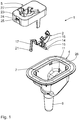
- eine Explosions-Ansicht eines erfindungsgemäßen Intraokularlinsen-Aufbewahrungssystems,
- Fig. 2
- das in
Fig. 1 dargestellte Intraokularlinsen-Aufbewahrungssystem im zusammengesetzten Zustand, - Fig. 3
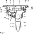
- einen Längs-Schnitt durch das in
Fig. 2 dargestellte Intraokularlinsen-Aufbewahrungssystem, wobei sich dessen Übergabe-Einrichtung in der Intraokularlinsen-Aufbewahrungs-Stellung befindet, - Fig. 4
- einen Längs-Schnitt durch das in
Fig. 2 dargestellte Intraokularlinsen-Aufbewahrungssystem, wobei sich dessen Übergabe-Einrichtung in der Intraokularlinsen-Übergabe-Stellung befindet, - Fig. 5
- eine Draufsicht auf eine Intraokularlinsen-Übergabe-Anordnung mit dem in
Fig. 2 dargestellten Intraokularlinsen-Aufbewahrungssystem, wobei sich die Injektions-Einrichtung in einer Ausgangs-Stellung befindet, - Fig. 6
- einen Längs-Schnitt durch die in
Fig. 5 dargestellte Intraokularlinsen-Übergabe-Anordnung gemäß der Schnittlinie VI-VI inFig. 5 , - Fig. 7
- eine Draufsicht gemäß
Fig. 5 , wobei sich die Injektions-Einrichtung in einer Einführ-Stellung befindet, - Fig. 8
- einen Längs-Schnitt durch die in
Fig. 7 dargestellte Intraokularlinsen-Übergabe-Anordnung gemäß der Schnittlinie VIII-VIII inFig. 7 , - Fig. 9
- eine Draufsicht gemäß
Fig. 5 , wobei sich die Injektions-Einrichtung in einer Übergabe-Stellung befindet, - Fig. 10
- einen Längs-Schnitt durch die in
Fig. 9 dargestellte Intraokularlinsen-Übergabe-Anordnung gemäß der Schnittlinie X-X inFig. 9 , - Fig. 11
- eine Draufsicht gemäß
Fig. 5 , wobei sich die Injektions-Einrichtung in einer Auszieh-Stellung befindet, und - Fig. 12
- einen Längs-Schnitt durch die in
Fig. 11 dargestellte Intraokularlinsen-Übergabe-Anordnung gemäß der Schnittlinie XII-XII inFig. 11 .
- Fig. 1
- an exploded view of an intraocular lens storage system according to the invention,
- Fig. 2
- this in
Fig. 1 illustrated intraocular lens storage system in the assembled state, - Fig. 3
- a longitudinal section through the in
Fig. 2 shown intraocular lens storage system, wherein its transfer device is in the intraocular lens storage position, - Fig. 4
- a longitudinal section through the in
Fig. 2 shown intraocular lens storage system, wherein its transfer device is in the intraocular lens transfer position, - Fig. 5
- a plan view of an intraocular lens transfer arrangement with the in
Fig. 2 shown intraocular lens storage system, wherein the injection device is in an initial position, - Fig. 6
- a longitudinal section through the in
Fig. 5 shown intraocular lens transfer arrangement according to the section line VI-VI inFig. 5 . - Fig. 7
- a plan view according to
Fig. 5 with the injection device in an insertion position, - Fig. 8
- a longitudinal section through the in
Fig. 7 shown intraocular lens transfer arrangement according to the section line VIII-VIII inFig. 7 . - Fig. 9
- a plan view according to
Fig. 5 with the injection device in a transfer position, - Fig. 10
- a longitudinal section through the in
Fig. 9 shown intraocular lens transfer arrangement according to the section line XX inFig. 9 . - Fig. 11
- a plan view according to
Fig. 5 , wherein the injection device is in a pull-out position, and - Fig. 12
- a longitudinal section through the in
Fig. 11 shown intraocular lens transfer arrangement according to the section line XII-XII inFig. 11 ,
Ein Intraokularlinsen-Aufbewahrungssystem umfasst ein Aufbewahrungs-Behältnis 1 und eine in dem Aufbewahrungs-Behältnis 1 angeordnete Übergabe-Einrichtung 2, die zwischen einer Intraokularlinsen-Aufbewahrungs-Stellung und einer von der Intraokularlinsen-Aufbewahrungs-Stellung entfernten Intraokularlinsen-Übergabe-Stellung durch manuelle Betätigung beweglich ist. In der Intraokularlinsen-Aufbewahrungs-Stellung ist eine Intraokularlinse (nicht dargestellt) sicher und steril in dem Aufbewahrungs-Behältnis 1 aufbewahrt, während in der Intraokularlinsen-Übergabe-Stellung eine Übergabe der Intraokularlinse an eine Injektions-Einrichtung 3 möglich ist. Mittels der Injektions-Einrichtung 3 ist eine Implantation der Intraokularlinse in das Auge eines Patienten möglich.An intraocular lens storage system comprises a
Das Aufbewahrungs-Behältnis 1 umfasst einen Aufbewahrungs-Behältnis-Grundkörper 4 und eine Verschluss-Einrichtung 5, die im zusammengesetzten Zustand fest, aber vorzugsweise wieder lösbar, miteinander verbunden sind.The
Der Aufbewahrungs-Behältnis-Grundkörper 4 hat eine äußere Wandung 6. Die Wandung 6 begrenzt eine Aufnahme-Öffnung 7, so dass dort der Aufbewahrungs-Behältnis-Grundkörper 4 nach außen offen ist. Der Aufbewahrungs-Behältnis-Grundkörper 4 hat einen ersten Teil-Abschnitt 8, der sich an die Aufnahme-Öffnung 7 anschließt und durch die Wandung 6 nach außen begrenzt ist. An den ersten Teil-Abschnitt 8 schließt sich wiederum ein zweiter Teil-Abschnitt 9 des Aufbewahrungs-Behältnis-Grundkörpers 4 an, der gegenüber dem ersten Teil-Abschnitt 8 verjüngt ist und durch die Wandung 6 nach außen begrenzt ist.The storage container base body 4 has an
Im Bereich des ersten Teil-Abschnitts 8 ist der Aufbewahrungs-Behältnis-Grundkörper 4 nach seitlich außen durch eine Seiten-Wandung 10 begrenzt, die im Wesentlichen senkrecht zu einem endseitigen, flanschartigen Seiten-Steg 11 verläuft. Der Seiten-Steg 11 verläuft im Wesentlichen in einer Ebene. In dieser Ebene liegt auch die Aufnahme-Öffnung 7.In the area of the
An die Seiten-Wandung 10 schließt sich ein Haupt-Boden 12 an, der gegenüberliegend zu der Aufnahme-Öffnung 7 angeordnet ist und vorzugsweise bereichsweise schräg zu der Seiten-Wandung 10 verläuft.The
An den Haupt-Boden 12 schließt sich ein endseitig geschlossenes Vertiefungs-Stück 13 an, das im Wesentlichen rohrartig ausgeführt ist. Das Vertiefungs-Stück 13 erstreckt sich senkrecht zu der Ebene, in der die Aufnahme-Öffnung 7 liegt. Das Vertiefungs-Stück 13 hat eine QuerschnittsFläche, die kleiner, vorzugsweise wesentlich kleiner, als die Fläche der Aufnahme-Öffnung 7 ist. Das Vertiefungs-Stück 13 ist durch eine Vertiefungs-Steg-Wandung 22 begrenzt.At the
Die Übergabe-Einrichtung 2 ist einteilig. Sie hat ein Lager-Stück 14, das länglich ausgeführt ist und im Querschnitt im Wesentlichen kreisringartig bzw. kreisförmig ausgebildet ist. Mit dem Lager-Stück 14 ist umfangsseitig ein Kopplungs-Ansatz 16 fest verbunden, von welchem wiederum ein Rückführungs-Feder-Mittel 17 seitlich ausgeht. Das Rückführungs-Feder-Mittel 17 geht beabstandet zu dem Lager-Stück 14 von dem Kopplungs-Ansatz 16 aus und ist ursprünglich mehrfach abgewinkelt. Es ist länglich und leistenartig.The
Ferner ist mit dem Lager-Stück 14 ein Intraokularlinsen-Aufnahme-Körper 18 umfangsseitig fest verbunden. Der Intraokularlinsen-Aufnahme-Körper 18 hat eine freie Anlage-Fläche bzw. -Kante 19, die vorzugsweise im Wesentlichen tangential zu dem Lager-Stück 14 verläuft. Gegenüberliegend zu der Anlage-Fläche 19 hat der Intraokularlinsen-Aufnahme-Körper 18 eine Intraokularlinsen-Aufnahme 20, die in senkrechter Richtung beabstandet zu der Anlage-Fläche 19 angeordnet ist. Wenn die Intraokularlinsen-Aufnahme 20 bestückt ist, ist in der Intraokularlinsen-Aufnahme 20 eine Intraokularlinse (nicht dargestellt) sicher, aber auch wieder abgebbar, gehalten.Further, an intraocular
Das Lager-Stück 14 ist in mindestens einer Lager-Aufnahme (nicht dargestellt) schwenkbar gehalten, die benachbart zu dem Vertiefungs-Stück 13 an dem Haupt-Boden 12 angebracht ist und eine Verschwenkung der Übergabe-Einrichtung 2 um eine Lager-Achse 15 erlaubt. Über die mindestens eine Lager-Aufnahme ist die Übergabe-Einrichtung 2 an dem Aufbewahrungs-Behältnis 1 bzw. dessen Haupt-Boden 12 gelagert. Die Übergabe-Einrichtung 2 ist wippenartig ausgeführt.
Das Rückführungs-Feder-Mittel 17 stützt sich dabei an dem Aufbewahrungs-Behältnis 1, genauer betrachtet in dem ersten Teil-Abschnitt 8, innenseitig ab. Es ist von Vorteil, wenn ein Bereich 21 des Rückführungs-Feder-Mittels 17 an dem Aufbewahrungs-Behältnis 1 räumlich festgelegt ist.
Die Wandung 6 ist durch die Seiten-Wandung 10, den Haupt-Boden 12 und die Vertiefungs-Steg-Wandung 22 gebildet.
In die Aufnahme-Öffnung 7 ist im montierten Zustand des Intraokularlinsen-Aufbewahrungssystems die Verschluss-Einrichtung 5 formschlüssig eingesetzt. Die Verschluss-Einrichtung 5 ist deckelartig und weist einen Deckel-Abschnitt 23 auf, der sich im eingesetzten Zustand der Verschluss-Einrichtung 5 in etwa in der Ebene des Seiten-Stegs 11 befindet und im Wesentlichen die Aufnahme-Öffnung 7 verschließt. Ferner hat die Verschluss-Einrichtung 5 einen Seiten-Steg 24, der ungefähr senkrecht zu dem Deckel-Abschnitt 23 verläuft und innenseitig mindestens bereichsweise an der Seiten-Wandung 10 anliegt. An dem Seiten-Steg 24 ist mindestens ein erstes Rast-Mittel 25 außenseitig angeordnet, das im eingesetzten Zustand der Verschluss-Einrichtung 5 mit einem entsprechenden Gegen-Rast-Mittel 26 an der Seiten-Wandung 10 rastend wechselwirkt.The bearing
The return spring means 17 is supported on the
The
In the receiving
In dem Deckel-Abschnitt 23 befindet sich eine Injektions-Einrichtungs-Haupt-Einführöffnung 27 die nach dem Vertiefungs-Stück 13 ausgerichtet ist und den Deckel-Abschnitt 23 vollständig durchdringt.In the
Von der Injektions-Einrichtungs-Haupt-Einführöffnung 27 geht seitlich eine Positionierungs-Einführöffnung 28 aus, die den Deckel-Abschnitt 23 vollständig durchdringt und sich von außen in Richtung auf den Haupt-Boden 12 des Aufbewahrungs-Behältnis-Grundkörpers 4 verjüngt. Die Positionierungs-Einführöffnung 28 ist so durch zwei einander gegenüberliegende Seiten-Wände 29 seitlich begrenzt, die an dem Deckel-Abschnitt 23 angeordnet sind und von außen in Richtung auf den Haupt-Boden 12 zusammenlaufen.From the injection device
Zwischen einer der Seiten-Wände 29 und der Injektions-Einrichtungs-Haupt-Einführöffnung 27 ist ein Steg-Vorsprung 30 angeordnet, der in die Injektions-Einrichtungs-Haupt-Einführöffnung 27 seitlich ragt.Between one of the
Ferner schließt sich an die Injektions-Einrichtungs-Haupt-Einführöffnung 27 seitlich eine Positionierungs-Ausführöffnung 31 an, die seitlich beabstandet zu der Positionierungs-Einführöffnung 28 in dem Deckel-Abschnitt 23 angeordnet ist und den Deckel-Abschnitt 23 vollständig durchdringt. Die Positionierungs-Ausführöffnung 31 ist wieder durch zwei einander gegenüberliegende Seiten-Wände 32 seitlich begrenzt. Die die Positionierungs-Ausführöffnung 31 begrenzenden Seiten-Wände 32 verlaufen im Wesentlichen parallel zueinander.Further, the injector
Zwischen der der Positionierungs-Einführöffnung 28 benachbarten Seiten-Wand 32 und der Injektions-Einrichtungs-Haupt-Einführöffnung 27 ist ein Steg-Vorsprung 33 im Bereich der Injektions-Einrichtungs-Haupt-Einführöffnung 27 an dem Deckel-Abschnitt 23 vorgesehen, der die Durchgangs-Verbindung zwischen der Positionierungs-Ausführöffnung 31 und der Injektions-Einrichtungs-Haupt-Einführöffnung 27 reduziert.Between the
Ferner springt von dem Deckel-Abschnitt 23 ein Blockier-Vorsprung 34 seitlich von der der Positionierungs-Einführöffnung 28 entfernten Seiten-Wand 32 in Richtung auf die gegenüberliegende Seiten-Wand 32 vor. Der Blockier-Vorsprung 34 ist außenseitig bündig mit dem Deckel-Abschnitt 23, weist jedoch eine geringere Dicke als der Deckel-Abschnitt 23 auf.Further, from the
Außerdem schließt sich eine Durchtritts-Öffnung 35 seitlich an die Injektions-Einrichtungs-Haupt-Einführöffnung 27 an. Die Durchtritts-Öffnung 35 ist in dem Deckel-Abschnitt 23 ausgebildet und durchdringt diesen vollständig. Die Positionierungs-Ausführöffnung 31 ist zwischen der Durchtritts-Öffnung 35 und der Positionierungs-Einführöffnung 28 angeordnet. Die Durchtritts-Öffnung 35 ist durch zwei einander gegenüberliegende Seiten-Wände 36 seitlich begrenzt, die parallel zueinander verlaufen.In addition, a
An die Injektions-Einrichtungs-Haupt-Einführöffnung 27 schließt sich seitlich ferner eine Begrenzungs-Öffnung 45 an, die benachbart zu der Positionierungs-Einführöffnung 28 in dem Deckel-Abschnitt 23 angeordnet ist. Die Begrenzungs-Öffnung 45 ist zwischen der Positionierungs-Einführöffnung 28 und der Durchtritts-Öffnung 35 angeordnet.The injection device
Der Steg-Vorsprung 30 ist der Begrenzungs-Öffnung 45 zugewandt. Der Blockier-Vorsprung 34 springt im Wesentlichen von der Durchtritts-Öffnung 35 weg.The
Wie bereits erwähnt, ist die in dem Intraokularlinsen-Aufbewahrungssystem aufbewahrte Intraokularlinse durch die Injektions-Einrichtung 3 in das Auge eines Patienten implantierbar. Die Injektions-Einrichtung 3 ist als Injektor ausgebildet und hat ein längliches, rohrartiges Gehäuse 37 sowie eine Längs-Mittel-Achse 38.As already mentioned, the intraocular lens stored in the intraocular lens storage system is implantable by the
Die Injektions-Einrichtung 3 weist außerdem an einem ersten Ende 39 des Gehäuses 37 einen Halte- bzw. Abstütz-Vorsprung 40 auf, der gegenüber der Längs-Mittel-Achse 38 radial vorspringt. Ferner hat die Injektions-Einrichtung 3 ein zweites Ende 41. Benachbart zu dem zweiten Ende 41 ist in das Gehäuse 37 ein sich außenseitig verjüngender Verjüngungs-Körper 42 eingesetzt, der hohl ausgeführt ist.The
Die Injektions-Einrichtung 3 hat außerdem eine Lade-Kammer 43, die zumindest teilweise seitlich offen ist und benachbart zu dem zweiten Ende 41 angeordnet ist. Ferner umfasst die Injektions-Einrichtung 3 eine Injektions-Kartusche 47, die in der Lade-Kammer 43 angeordnet ist.The
Gegenüberliegend zu der Öffnung der Lade-Kammer 43 ist seitlich an dem Gehäuse 37 ein längs verlaufender Führungs-Steg 44 angeordnet.Opposite to the opening of the
In dem Gehäuse 37 ist ein Betätigungs-Kolben (nicht dargestellt) in Richtung auf das zweite Ende 41 verschiebbar geführt. Der Betätigungs-Kolben ist mit einer Kolben-Stange (nicht dargestellt) fest verbunden, die das Gehäuse 37 axial durchsetzt und gegenüber dem ersten Ende 39 nach außen vorsteht. Der Betätigungs-Kolben ist durch die Kolben-Stange betätigbar. Durch Verschiebung des Betätigungs-Kolbens ist eine in der Lade-Kammer 43 bzw. Injektions-Kartusche 47 angeordnete Intraokularlinse durch den Verjüngungs-Körper 42 führbar und dann in das Auge eines Patienten implantierbar.In the
Die Injektions-Kartusche 47 ist im Wesentlichen durch ein Rohrstück 49 gebildet, das sich in einer Einführ-Richtung der Injektions-Einrichtung 3 erstreckt. Das Rohrstück 49 begrenzt nach seitlich außen einen Intraokularlinsen-Aufnahmeraum 50. Es hat einen Mantel, der in der Längs-Richtung des Rohrstücks 49 aufgetrennt bzw. unterbrochen ist, sodass das Rohrstück 49 dort aufklappbar bzw. zusammenklappbar ist. Das Rohrstück 49 hat so durch die Längs-Unterbrechung zwei längs verlaufende Klappen-Bereiche mit freien End-Kanten 51 bzw. 52. Die End-Kanten 51, 52 sind im Wesentlichen benachbart zueinander angeordnet und liegen im Wesentlichen einander gegenüber. Das Rohrstück 49 ist im Querschnitt im Wesentlichen kreisbogenförmig. Das Rohrstück 49 ist als Klapp-Stück ausgeführt.The
Die Injektions-Kartusche 47 hat außerdem einen ersten Führungs-Flügel 53 und einen zweiten Führungs-Flügel (nicht dargestellt), die im Wesentlichen plattenartig ausgeführt sind und sich nach seitlich außen bzw. in radialer Richtung zu der Längs-Mittel-Achse 38 erstrecken. An jedem Klappen-Bereich ist ein Führungs-Flügel 53 an dem Rohrstück 49 angeordnet. Die Anschluss-Bereiche der Führungs-Flügel 53 verlaufen parallel zu den End-Kanten 51, 52 und vorzugsweise auch benachbart zu diesen.The
Das Intraokularlinsen-Aufbewahrungssystem und die Injektions-Einrichtung 3 bilden zusammen eine Intraokularlinsen-Übergabe-Anordnung.The intraocular lens storage system and the
Nachfolgend wird der Einsatz der Intraokularlinsen-Übergabe-Anordnung näher beschrieben.The use of the intraocular lens transfer arrangement will be described in more detail below.
Die Verschluss-Einrichtung 5 ist in die Aufnahme-Öffnung 7 eingesetzt und ist dort rastend an dem Aufbewahrungs-Behältnis-Grundkörper 4 festgelegt. Die Übergabe-Einrichtung 2 befindet sich in ihrer ursprünglichen Intraokularlinsen-Aufbewahrungs-Stellung. Dabei liegt die Anlage-Fläche 19 innenseitig an dem Haupt-Boden 12 an. In der Intraokularlinsen-Aufnahme 20 ist eine Intraokularlinse aufgenommen.The
Gemäß
Anschließend wird die Injektions-Einrichtung 3 weiter in das Aufbewahrungs-Behältnis 1 längs der Längs-Mittel-Achse 38 in einer Einführ-Richtung durch Aufbringen einer entsprechenden Einführ-Kraft eingeführt. Dabei drückt der Betätigungs-Vorsprung 46 auf den Kopplungs-Ansatz 16, so dass die Übergabe-Einrichtung 2 um die Lager-Achse 15 in ihre Intraokularlinsen-Übergabe-Stellung geschwenkt wird. Die Anlage-Fläche 19 wird von dem Haupt-Boden 12 abgehoben. Die Lager-Achse 15 verläuft senkrecht zu der Einführ-Richtung. Der Kopplungs-Ansatz 16 bildet also ein Betätigungs-Mittel zur Betätigung der Übergabe-Einrichtung 2. Dabei wird die Übergabe-Einrichtung 2 um etwa 15° bis 90°, bevorzugter um etwa 40° bis 75°, verschwenkt. In der Intraokularlinsen-Übergabe-Stellung befindet sich die Intraokularlinsen-Aufnahme 20 in der Injektions-Kartusche 47 bzw. benachbart zu dieser. Genauer betrachtet befindet sich die Intraokularlinse in der Intraokularlinsen-Übergabe-Stellung in der Übergabe-Einrichtung 2 unmittelbar vor dem Intraokularlinsen-Aufnahmeraum 50. Durch die Schwenk-Bewegung der Übergabe-Einrichtung 2 wird das längliche Rückführungs-Feder-Mittel 17 gebogen und gespannt. Es erzeugt so eine Rückführungs-Kraft. Ein weiteres axiales Einführen der Injektions-Einrichtung 3 wird durch einen Anschlag der Intraokularlinse an dem Rohrstück 49 verhindert. Der erste Führungs-Flügel 53 durchsetzt dabei die Durchtritts-Öffnung 35. Er ist dabei zwischen den beiden Seiten-Wänden 36 angeordnet, die ein Verschwenken der Injektions-Kartusche 47 um die Längs-Mittel-Achse 38 durch Anschlag an dem ersten Führungs-Flügel 53 verhindern.Subsequently, the
Der zweite Führungs-Flügel durchsetzt dabei die Positionierungs-Einführöffnung 28. Die beiden Führungs-Flügel 53 sind für das Durchsetzen der Öffnungen 28, 35 entsprechend durch Aufbiegen des Rohrstücks 49 aufzuklappen bzw. auseinander zu schwenken, sodass eine Einführung der Führungs-Flügel 53 durch die Öffnungen 28, 35 möglich ist.The two
Bezugnehmend auf die
Bei einer Rückbewegung der Übergabe-Einrichtung 2 in die Intraokularlinsen-Aufbewahrungs-Stellung wird die Intraokularlinse durch die Klappen-Bereiche aus der Übergabe-Einrichtung 2 gelöst und in den Intraokularlinsen-Aufnahmeraum 50 übergeben.Upon return movement of the
Nach Abschluss der Schwenk-Bewegung steht der durch die Positionierungs-Einführöffnung 28 eingeführte zweite Führungs-Flügel in einer zweiten, verschwenkten Position, sodass er nach der Positionierungs-Ausführöffnung 31 ausgerichtet ist.Upon completion of the pivotal movement, the second guide vane inserted through the
Anschließend wird die Injektions-Einrichtung 3 entgegen der Einführ-Richtung wieder aus dem Aufbewahrungs-Behältnis 1 entfernt (
Die Intraokularlinse kann nun mit der Injektions-Einrichtung 3 in das Auge eines Patienten implantiert werden.The intraocular lens can now be implanted with the
Claims (13)
- Intraocular lens storage system for storing an intraocular lens, comprisinga) a storage container (1) for storing the intraocular lens, andb) an actuable transfer device (2), which is arranged in the storage container (1), with an intraocular lens receiver (20) for receiving the intraocular lens, wherein the transfer device (2) is movable betweeni) an intraocular lens storage position for storing the intraocular lens in the storage container (1), andii) an intraocular lens transfer position for transferring the intraocular lens to an injection device (3)c) wherein an injection device main introduction opening (27) for introducing the injection device (3) into the storage container (1) is formed in the storage container (1),
characterized in thatd) the injection device main introduction opening (27) is laterally adjoined byi) an injection device through-opening (35) for aligning a first guide wing (53) of the injection device (3) during introduction, andii) an injection device positioning introduction opening (28) for aligning a second guide wing of the injection device (3) on introduction as well asiii) an injection device positioning removal opening (31) to align the second guide wing of the injection device (3) on removal. - Intraocular lens storage system according to claim 1, characterized in that the storage container (1) has at least one actuating means coupled to the transfer device (2) for moving the transfer device (2) between the intraocular lens storage position and the intraocular lens transfer position.
- Intraocular lens storage system according to claim 1, characterized in that the transfer device (2) has at least one actuating means (16), which is arranged for the movement thereof between the intraocular lens storage position and the intraocular lens transfer position, for actuation by introducing the injection device (3) into the storage container (1).
- Intraocular lens storage system according to any one of the preceding claims, characterized in that the transfer device (2) is pivotably mounted on the storage container (1).
- Intraocular lens storage system according to any one of the preceding claims, characterized in that at least one return spring means (17), which upon movement of the transfer device (2) into the intraocular lens transfer position produces a transfer device return force to return the transfer device (2) into the intraocular lens storage position, is connected to the transfer device (2).
- Intraocular lens storage system according to any one of the preceding claims, characterized by an injection device introduction stop for limiting the introduction movement of the injection device (3) into the storage container (1).
- Intraocular lens storage system according to any one of the preceding claims, characterized in that the faces (29, 32) limiting the injection device positioning introduction opening (28) and the injection device positioning removal opening (31) have at least one pivoting link for forcing a pivoting movement of the at least partially introduced injection device (3) about the longitudinal centre axis (38) thereof relative to the storage container (1) to transfer the intraocular lens.
- Intraocular lens storage system according to claim 7, characterized in that the at least one pivoting link has a pivoting link face on the storage container (1), said pivoting link face running obliquely and/or transversely to an introduction direction of the injection device (3) into the storage container (1).
- Intraocular lens storage system according to claim 7 or 8, characterized in that a pivot stop (30) on the storage container (1) limits the maximum pivoting movement of the injection device (3) relative to the storage container (1).
- Intraocular lens transfer arrangementa) with an intraocular lens storage system according to any one of the preceding claims, andb) with an injection device (3) for introduction into the storage container (1) of the intraocular lens storage system,c) wherein the transfer device (2) in the intraocular lens transfer position transfers the intraocular lens to the injection device (3) for implantation.
- Intraocular lens transfer arrangement according to claim 10, characterized in that the injection device (3) comprises an injection cartridge (47), wherein the injection cartridge (47) is formed by a folding piece (49) with two free folding regions, which are movable in relation to one another and in each case carry a guide wing (53) running laterally outwardly.
- Intraocular lens transfer arrangement according to claim 11, characterized in that the guide wings (53), on introduction of the injection device (3), pass through the injection device positioning introduction opening (28) and the injection device through-opening (35), said openings laterally adjoining the injection device main introduction opening (27).
- Method for transferring an intraocular lens to an injection device (3), comprising- providing an intraocular lens storage system according to any one of claims 1 to 9, and- actuating the transfer device (2) to move it from the intraocular lens storage position into the intraocular lens transfer position to transfer the intraocular lens to the injection device (3).
Priority Applications (1)
| Application Number | Priority Date | Filing Date | Title |
|---|---|---|---|
| PL13805865T PL2934381T3 (en) | 2012-12-20 | 2013-12-13 | Intraocular lens storage system |
Applications Claiming Priority (2)
| Application Number | Priority Date | Filing Date | Title |
|---|---|---|---|
| DE102012223885.9A DE102012223885B4 (en) | 2012-12-20 | 2012-12-20 | Intraocular lens storage system, transfer arrangement and method for transferring an intraocular lens to an injection device |
| PCT/EP2013/076504 WO2014095611A1 (en) | 2012-12-20 | 2013-12-13 | Intraocular lens storage system |
Publications (2)
| Publication Number | Publication Date |
|---|---|
| EP2934381A1 EP2934381A1 (en) | 2015-10-28 |
| EP2934381B1 true EP2934381B1 (en) | 2018-09-05 |
Family
ID=49766083
Family Applications (1)
| Application Number | Title | Priority Date | Filing Date |
|---|---|---|---|
| EP13805865.6A Active EP2934381B1 (en) | 2012-12-20 | 2013-12-13 | Intraocular lens storage system |
Country Status (9)
| Country | Link |
|---|---|
| US (1) | US9763775B2 (en) |
| EP (1) | EP2934381B1 (en) |
| CN (1) | CN104869947B (en) |
| BR (1) | BR112015014208B1 (en) |
| DE (1) | DE102012223885B4 (en) |
| ES (1) | ES2699973T3 (en) |
| PL (1) | PL2934381T3 (en) |
| RU (1) | RU2623123C2 (en) |
| WO (1) | WO2014095611A1 (en) |
Families Citing this family (10)
| Publication number | Priority date | Publication date | Assignee | Title |
|---|---|---|---|---|
| US10835373B2 (en) | 2002-12-12 | 2020-11-17 | Alcon Inc. | Accommodating intraocular lenses and methods of use |
| US8968396B2 (en) | 2007-07-23 | 2015-03-03 | Powervision, Inc. | Intraocular lens delivery systems and methods of use |
| US10299913B2 (en) | 2009-01-09 | 2019-05-28 | Powervision, Inc. | Accommodating intraocular lenses and methods of use |
| US10433949B2 (en) | 2011-11-08 | 2019-10-08 | Powervision, Inc. | Accommodating intraocular lenses |
| DE102012223885B4 (en) * | 2012-12-20 | 2022-01-05 | Humanoptics Ag | Intraocular lens storage system, transfer arrangement and method for transferring an intraocular lens to an injection device |
| EP3785668A1 (en) | 2013-03-15 | 2021-03-03 | Alcon Inc. | Intraocular lens storage and loading devices and methods of use |
| WO2017079733A1 (en) | 2015-11-06 | 2017-05-11 | Powervision, Inc. | Accommodating intraocular lenses and methods of manufacturing |
| BE1024131B1 (en) | 2016-04-21 | 2017-11-20 | Physiol S.A. | Soft intraocular lens injection device and storage shuttle for its implementation |
| CN109124827A (en) * | 2018-08-10 | 2019-01-04 | 河南宇宙人工晶状体研制有限公司 | A kind of intraocular lens' preassembling device |
| US11678973B2 (en) * | 2020-05-27 | 2023-06-20 | EyeYon Medical Ltd. | Corneal implant injector system |
Family Cites Families (50)
| Publication number | Priority date | Publication date | Assignee | Title |
|---|---|---|---|---|
| US4173281A (en) * | 1978-06-12 | 1979-11-06 | Intermedics Intraocular, Inc. | Intraocular lens packaging system |
| US4257521A (en) * | 1979-11-16 | 1981-03-24 | Stanley Poler | Packaging means for an intraocular lens |
| US4423809A (en) * | 1982-02-05 | 1984-01-03 | Staar Surgical Company, Inc. | Packaging system for intraocular lens structures |
| US5019084A (en) * | 1986-08-06 | 1991-05-28 | Minnesota Mining And Manufacturing Company | Corneal holder |
| US4697697A (en) * | 1986-08-18 | 1987-10-06 | Coopervision, Inc. | Method and apparatus for packaging an intraocular lens |
| US4862885A (en) * | 1988-05-25 | 1989-09-05 | Cumming J Stuart | Instrument for inserting a deformable intraocular lens into the eye |
| US5171241A (en) * | 1989-06-09 | 1992-12-15 | Ioptex Research Inc. | Device for folding an intraocular lens and holding it in the folded state |
| RU2059416C1 (en) * | 1992-11-23 | 1996-05-10 | Институт биофизики клетки РАН | Device for prolonged sterile storing of artificial optical lenses |
| US5578042A (en) * | 1994-03-14 | 1996-11-26 | Cumming; J. Stuart | Ophthalmic kit and method for lens insertion |
| CN1118247A (en) * | 1994-09-09 | 1996-03-13 | 佳能星股份有限公司 | Deformable tools for inserting lens into eye |
| US6228094B1 (en) | 1995-11-01 | 2001-05-08 | Micro Medical Devices, Inc. | Lens storage and folding apparatus |
| US6183513B1 (en) * | 1998-06-05 | 2001-02-06 | Bausch & Lomb Surgical, Inc. | Intraocular lens packaging system, method of producing, and method of using |
| US6360883B1 (en) * | 1999-03-09 | 2002-03-26 | Opthalmic Innovations, Inc. | Packaging for artificial lens |
| US6386357B1 (en) * | 1999-07-12 | 2002-05-14 | Hoya Healthcare Corporation | Soft intraocular lens-folding device and storage case |
| JP3728155B2 (en) * | 1999-10-05 | 2005-12-21 | キヤノンスター株式会社 | Intraocular lens insertion system |
| US6471708B2 (en) * | 2000-12-21 | 2002-10-29 | Bausch & Lomb Incorporated | Intraocular lens and additive packaging system |
| US6537283B2 (en) * | 2001-08-17 | 2003-03-25 | Alcon, Inc. | Intraocular lens shipping case and injection cartridge |
| US20030045930A1 (en) * | 2001-08-30 | 2003-03-06 | Allergan Sales, Inc. | Apparatus and methods for packaging intrcorneal implants and facilitating placement thereof |
| EP1434541A2 (en) * | 2001-10-12 | 2004-07-07 | Humanoptics AG | Device for folding an intraocular lens and system for storing an intraocular lens |
| FR2833154B1 (en) * | 2001-12-12 | 2004-11-19 | Ioltechnologie Production | CASSETTE AND FLEXIBLE INTRAOCULAR LENS INJECTOR AND METHOD FOR INJECTING SUCH LENSES |
| US6733507B2 (en) * | 2002-04-12 | 2004-05-11 | Advanced Medical Optics, Inc. | Intraocular lens insertion apparatus |
| FR2848182B1 (en) * | 2002-12-04 | 2006-02-03 | Eurocrystal | METHOD AND DEVICE FOR STERILE PACKAGING OF A SOFT HYDROPHILIC INTRAOCULAR LENS READY FOR USE |
| US8403941B2 (en) * | 2003-06-02 | 2013-03-26 | Abbott Medical Optics Inc. | Intraocular lens and cartridge packaging with lens-loading function |
| US7422604B2 (en) * | 2003-08-28 | 2008-09-09 | Bausch & Lomb Incorporated | Preloaded IOL injector |
| US7429263B2 (en) * | 2003-08-28 | 2008-09-30 | Bausch & Lomb Incorporated | Preloaded IOL injector |
| IL157979A0 (en) * | 2003-09-17 | 2004-03-28 | Hanita Lenses | Packaging system for intraocular lens |
| RU36216U1 (en) * | 2003-09-22 | 2004-03-10 | Государственное учреждение Межотраслевой научно-технический комплекс "Микрохирургия глаза" им. акад. С.Н. Федорова | Artificial Eye Implant Storage Container |
| US7281699B2 (en) * | 2003-12-29 | 2007-10-16 | Bausch & Lomb Incorporated | Universal accommodating IOL holder for lens processing and packaging |
| US7458976B2 (en) * | 2005-03-02 | 2008-12-02 | Advanced Medical Optics, Inc. | Devices and methods for storing, loading, and delivering an intraocular lens |
| DE202004017931U1 (en) * | 2004-08-12 | 2005-01-13 | Medicel Ag | Device for loading a lens folding cartridge with an intraocular lens, as well as lens folding cartridge and set for implantation |
| FR2875125B1 (en) * | 2004-09-13 | 2006-12-01 | Patrick Meunier | DEVICE FOR LOADING AN INTRAOCULAR LENS IN AN INJECTION CARTRIDGE |
| US20060142781A1 (en) * | 2004-12-29 | 2006-06-29 | Joel Pynson | Preloaded IOL injector and method |
| WO2006070219A1 (en) * | 2004-12-29 | 2006-07-06 | BAUSCH & LOMB INCORPORATED Société américaine régie selon les lois de New York | Preloaded iol injector |
| US20060142780A1 (en) * | 2004-12-29 | 2006-06-29 | Joel Pynson | Preloaded IOL injector and method |
| US8562674B2 (en) * | 2005-02-11 | 2013-10-22 | Abbott Medical Optics Inc. | Front loading IOL insertion apparatus and method of using |
| US9339374B2 (en) * | 2005-02-11 | 2016-05-17 | Abbot Medical Optics Inc. | Intraocular lens insertion apparatus and lens case |
| US8435289B2 (en) * | 2005-02-11 | 2013-05-07 | Abbott Medical Optics Inc. | Rapid exchange IOL insertion apparatus and methods of using |
| JP4836046B2 (en) * | 2005-02-24 | 2011-12-14 | Hoya株式会社 | Intraocular lens insertion device |
| US8475526B2 (en) * | 2005-12-22 | 2013-07-02 | Bausch & Lomb Incorporated | Apparatus and methods for loading of an IOL injector |
| US20070150054A1 (en) * | 2005-12-22 | 2007-06-28 | Joel Pynson | Apparatus and methods for loading of an IOL injector |
| DE102006000929B4 (en) * | 2006-01-05 | 2010-09-23 | *Acri.Tec Gmbh | Injector for intraocular lenses |
| US8435288B2 (en) * | 2006-09-22 | 2013-05-07 | Lenstec Barbados Inc. | System and method for storing, shipping and injecting ocular devices |
| US20080147080A1 (en) * | 2006-12-13 | 2008-06-19 | Joel Pynson | Injector apparatus for use with intraocular lenses and methods of use |
| US20080154361A1 (en) * | 2006-12-22 | 2008-06-26 | Joel Pynson | Intraocular lens injector subassembly |
| US20090057167A1 (en) * | 2007-08-30 | 2009-03-05 | Rathert Brian D | Intraocular Lens Packaging |
| CH699588A1 (en) * | 2008-09-22 | 2010-03-31 | Medicel Ag | Cartridge for an intraocular lens injector system and for it. |
| GB2472872B (en) * | 2009-08-18 | 2014-12-31 | Carl Zeiss Meditec Sas | Holding device for an intraocular lens, packaging and transport means for an intraocular lens and injector device for an intraocular lens. |
| GB2472873A (en) * | 2009-08-18 | 2011-02-23 | Carl Zeiss Meditec Sas | Cassette for intraocular lens |
| USD707821S1 (en) * | 2012-11-30 | 2014-06-24 | Santen Pharmaceutical Co., Ltd. | Container for intraocular lens |
| DE102012223885B4 (en) * | 2012-12-20 | 2022-01-05 | Humanoptics Ag | Intraocular lens storage system, transfer arrangement and method for transferring an intraocular lens to an injection device |
-
2012
- 2012-12-20 DE DE102012223885.9A patent/DE102012223885B4/en not_active Expired - Fee Related
-
2013
- 2013-12-13 BR BR112015014208-7A patent/BR112015014208B1/en not_active IP Right Cessation
- 2013-12-13 PL PL13805865T patent/PL2934381T3/en unknown
- 2013-12-13 RU RU2015120918A patent/RU2623123C2/en active
- 2013-12-13 ES ES13805865T patent/ES2699973T3/en active Active
- 2013-12-13 CN CN201380066507.0A patent/CN104869947B/en not_active Expired - Fee Related
- 2013-12-13 WO PCT/EP2013/076504 patent/WO2014095611A1/en active Application Filing
- 2013-12-13 US US14/653,951 patent/US9763775B2/en active Active
- 2013-12-13 EP EP13805865.6A patent/EP2934381B1/en active Active
Also Published As
| Publication number | Publication date |
|---|---|
| US20150342730A1 (en) | 2015-12-03 |
| DE102012223885A1 (en) | 2014-06-26 |
| EP2934381A1 (en) | 2015-10-28 |
| PL2934381T3 (en) | 2019-02-28 |
| US9763775B2 (en) | 2017-09-19 |
| BR112015014208B1 (en) | 2022-02-22 |
| CN104869947B (en) | 2016-11-23 |
| RU2015120918A (en) | 2017-01-25 |
| RU2623123C2 (en) | 2017-06-22 |
| CN104869947A (en) | 2015-08-26 |
| WO2014095611A1 (en) | 2014-06-26 |
| ES2699973T3 (en) | 2019-02-13 |
| DE102012223885B4 (en) | 2022-01-05 |
| BR112015014208A2 (en) | 2017-09-26 |
Similar Documents
| Publication | Publication Date | Title |
|---|---|---|
| EP2934381B1 (en) | Intraocular lens storage system | |
| DE4341229C2 (en) | Pipette system | |
| DE60216265T2 (en) | IMPROVEMENTS IN SPRAY MOUNTS | |
| WO2000045746A1 (en) | Injector for implanting a folded intraocular lens, container for storing and transporting the injector and method for ejecting the lens in a folded state | |
| AT511538A1 (en) | FASTENING DEVICE FOR FASTENING A FRONT PANEL TO A DRAWER | |
| EP0084324A1 (en) | Device for changing the longitudinal position of a ski binding | |
| DE202009005256U1 (en) | Detent fitting and pullout guide | |
| DE202008014111U1 (en) | Abisolierzange | |
| AT511062A4 (en) | FASTENING DEVICE FOR FASTENING A FRONT PANEL TO A DRAWER | |
| WO2015070358A2 (en) | Device for receiving an intraocular lens, and method for folding an intraocular lens | |
| DE202008014110U1 (en) | Abisolierzange | |
| DE202010009794U1 (en) | Device with a power storage and a movably mounted opening element and furniture | |
| EP2130609B1 (en) | Discharge device for media | |
| EP1898810A1 (en) | Applicator | |
| EP2801688B1 (en) | Swing furniture with two push-to-open fittings | |
| DE3028571C2 (en) | Vacuum cleaner with a cover that closes off the dust compartment | |
| DE202008015378U1 (en) | Scalpel or surgical knife | |
| DE202009019167U1 (en) | Connector with unlocking | |
| DE202015006833U1 (en) | Bone punch with captive punch | |
| WO2009024254A2 (en) | Dry powder inhaler | |
| DE102012112882B4 (en) | Lancing device for obtaining body fluid samples | |
| WO2004110782A2 (en) | Writing utensil comprising a reservoir and an integrated sealing element | |
| EP2873634A1 (en) | Pneumatic tube capsule | |
| DE102011075338B3 (en) | Pneumatic tube carrier | |
| WO2016071487A1 (en) | Hinge for a toilet seat and toilet seat assembly |
Legal Events
| Date | Code | Title | Description |
|---|---|---|---|
| PUAI | Public reference made under article 153(3) epc to a published international application that has entered the european phase |
Free format text: ORIGINAL CODE: 0009012 |
|
| 17P | Request for examination filed |
Effective date: 20150622 |
|
| AK | Designated contracting states |
Kind code of ref document: A1 Designated state(s): AL AT BE BG CH CY CZ DE DK EE ES FI FR GB GR HR HU IE IS IT LI LT LU LV MC MK MT NL NO PL PT RO RS SE SI SK SM TR |
|
| AX | Request for extension of the european patent |
Extension state: BA ME |
|
| DAX | Request for extension of the european patent (deleted) | ||
| GRAP | Despatch of communication of intention to grant a patent |
Free format text: ORIGINAL CODE: EPIDOSNIGR1 |
|
| INTG | Intention to grant announced |
Effective date: 20180412 |
|
| RIN1 | Information on inventor provided before grant (corrected) |
Inventor name: MESSNER, ARTHUR Inventor name: HEISS, MARTIN CHRISTOPH |
|
| GRAS | Grant fee paid |
Free format text: ORIGINAL CODE: EPIDOSNIGR3 |
|
| GRAA | (expected) grant |
Free format text: ORIGINAL CODE: 0009210 |
|
| AK | Designated contracting states |
Kind code of ref document: B1 Designated state(s): AL AT BE BG CH CY CZ DE DK EE ES FI FR GB GR HR HU IE IS IT LI LT LU LV MC MK MT NL NO PL PT RO RS SE SI SK SM TR |
|
| REG | Reference to a national code |
Ref country code: GB Ref legal event code: FG4D Free format text: NOT ENGLISH |
|
| REG | Reference to a national code |
Ref country code: CH Ref legal event code: EP |
|
| REG | Reference to a national code |
Ref country code: AT Ref legal event code: REF Ref document number: 1036952 Country of ref document: AT Kind code of ref document: T Effective date: 20180915 |
|
| REG | Reference to a national code |
Ref country code: IE Ref legal event code: FG4D Free format text: LANGUAGE OF EP DOCUMENT: GERMAN |
|
| REG | Reference to a national code |
Ref country code: DE Ref legal event code: R096 Ref document number: 502013011037 Country of ref document: DE |
|
| REG | Reference to a national code |
Ref country code: NL Ref legal event code: FP |
|
| REG | Reference to a national code |
Ref country code: LT Ref legal event code: MG4D |
|
| PG25 | Lapsed in a contracting state [announced via postgrant information from national office to epo] |
Ref country code: RS Free format text: LAPSE BECAUSE OF FAILURE TO SUBMIT A TRANSLATION OF THE DESCRIPTION OR TO PAY THE FEE WITHIN THE PRESCRIBED TIME-LIMIT Effective date: 20180905 Ref country code: BG Free format text: LAPSE BECAUSE OF FAILURE TO SUBMIT A TRANSLATION OF THE DESCRIPTION OR TO PAY THE FEE WITHIN THE PRESCRIBED TIME-LIMIT Effective date: 20181205 Ref country code: SE Free format text: LAPSE BECAUSE OF FAILURE TO SUBMIT A TRANSLATION OF THE DESCRIPTION OR TO PAY THE FEE WITHIN THE PRESCRIBED TIME-LIMIT Effective date: 20180905 Ref country code: GR Free format text: LAPSE BECAUSE OF FAILURE TO SUBMIT A TRANSLATION OF THE DESCRIPTION OR TO PAY THE FEE WITHIN THE PRESCRIBED TIME-LIMIT Effective date: 20181206 Ref country code: LT Free format text: LAPSE BECAUSE OF FAILURE TO SUBMIT A TRANSLATION OF THE DESCRIPTION OR TO PAY THE FEE WITHIN THE PRESCRIBED TIME-LIMIT Effective date: 20180905 Ref country code: NO Free format text: LAPSE BECAUSE OF FAILURE TO SUBMIT A TRANSLATION OF THE DESCRIPTION OR TO PAY THE FEE WITHIN THE PRESCRIBED TIME-LIMIT Effective date: 20181205 Ref country code: FI Free format text: LAPSE BECAUSE OF FAILURE TO SUBMIT A TRANSLATION OF THE DESCRIPTION OR TO PAY THE FEE WITHIN THE PRESCRIBED TIME-LIMIT Effective date: 20180905 |
|
| REG | Reference to a national code |
Ref country code: ES Ref legal event code: FG2A Ref document number: 2699973 Country of ref document: ES Kind code of ref document: T3 Effective date: 20190213 |
|
| PG25 | Lapsed in a contracting state [announced via postgrant information from national office to epo] |
Ref country code: LV Free format text: LAPSE BECAUSE OF FAILURE TO SUBMIT A TRANSLATION OF THE DESCRIPTION OR TO PAY THE FEE WITHIN THE PRESCRIBED TIME-LIMIT Effective date: 20180905 Ref country code: HR Free format text: LAPSE BECAUSE OF FAILURE TO SUBMIT A TRANSLATION OF THE DESCRIPTION OR TO PAY THE FEE WITHIN THE PRESCRIBED TIME-LIMIT Effective date: 20180905 Ref country code: AL Free format text: LAPSE BECAUSE OF FAILURE TO SUBMIT A TRANSLATION OF THE DESCRIPTION OR TO PAY THE FEE WITHIN THE PRESCRIBED TIME-LIMIT Effective date: 20180905 |
|
| PG25 | Lapsed in a contracting state [announced via postgrant information from national office to epo] |
Ref country code: RO Free format text: LAPSE BECAUSE OF FAILURE TO SUBMIT A TRANSLATION OF THE DESCRIPTION OR TO PAY THE FEE WITHIN THE PRESCRIBED TIME-LIMIT Effective date: 20180905 Ref country code: IS Free format text: LAPSE BECAUSE OF FAILURE TO SUBMIT A TRANSLATION OF THE DESCRIPTION OR TO PAY THE FEE WITHIN THE PRESCRIBED TIME-LIMIT Effective date: 20190105 Ref country code: EE Free format text: LAPSE BECAUSE OF FAILURE TO SUBMIT A TRANSLATION OF THE DESCRIPTION OR TO PAY THE FEE WITHIN THE PRESCRIBED TIME-LIMIT Effective date: 20180905 Ref country code: CZ Free format text: LAPSE BECAUSE OF FAILURE TO SUBMIT A TRANSLATION OF THE DESCRIPTION OR TO PAY THE FEE WITHIN THE PRESCRIBED TIME-LIMIT Effective date: 20180905 |
|
| PG25 | Lapsed in a contracting state [announced via postgrant information from national office to epo] |
Ref country code: SM Free format text: LAPSE BECAUSE OF FAILURE TO SUBMIT A TRANSLATION OF THE DESCRIPTION OR TO PAY THE FEE WITHIN THE PRESCRIBED TIME-LIMIT Effective date: 20180905 Ref country code: SK Free format text: LAPSE BECAUSE OF FAILURE TO SUBMIT A TRANSLATION OF THE DESCRIPTION OR TO PAY THE FEE WITHIN THE PRESCRIBED TIME-LIMIT Effective date: 20180905 Ref country code: PT Free format text: LAPSE BECAUSE OF FAILURE TO SUBMIT A TRANSLATION OF THE DESCRIPTION OR TO PAY THE FEE WITHIN THE PRESCRIBED TIME-LIMIT Effective date: 20190105 |
|
| REG | Reference to a national code |
Ref country code: DE Ref legal event code: R097 Ref document number: 502013011037 Country of ref document: DE |
|
| PLBE | No opposition filed within time limit |
Free format text: ORIGINAL CODE: 0009261 |
|
| STAA | Information on the status of an ep patent application or granted ep patent |
Free format text: STATUS: NO OPPOSITION FILED WITHIN TIME LIMIT |
|
| PG25 | Lapsed in a contracting state [announced via postgrant information from national office to epo] |
Ref country code: DK Free format text: LAPSE BECAUSE OF FAILURE TO SUBMIT A TRANSLATION OF THE DESCRIPTION OR TO PAY THE FEE WITHIN THE PRESCRIBED TIME-LIMIT Effective date: 20180905 |
|
| 26N | No opposition filed |
Effective date: 20190606 |
|
| GBPC | Gb: european patent ceased through non-payment of renewal fee |
Effective date: 20181213 |
|
| PG25 | Lapsed in a contracting state [announced via postgrant information from national office to epo] |
Ref country code: MC Free format text: LAPSE BECAUSE OF FAILURE TO SUBMIT A TRANSLATION OF THE DESCRIPTION OR TO PAY THE FEE WITHIN THE PRESCRIBED TIME-LIMIT Effective date: 20180905 Ref country code: LU Free format text: LAPSE BECAUSE OF NON-PAYMENT OF DUE FEES Effective date: 20181213 Ref country code: SI Free format text: LAPSE BECAUSE OF FAILURE TO SUBMIT A TRANSLATION OF THE DESCRIPTION OR TO PAY THE FEE WITHIN THE PRESCRIBED TIME-LIMIT Effective date: 20180905 |
|
| REG | Reference to a national code |
Ref country code: IE Ref legal event code: MM4A |
|
| PG25 | Lapsed in a contracting state [announced via postgrant information from national office to epo] |
Ref country code: IE Free format text: LAPSE BECAUSE OF NON-PAYMENT OF DUE FEES Effective date: 20181213 |
|
| PG25 | Lapsed in a contracting state [announced via postgrant information from national office to epo] |
Ref country code: GB Free format text: LAPSE BECAUSE OF NON-PAYMENT OF DUE FEES Effective date: 20181213 |
|
| PG25 | Lapsed in a contracting state [announced via postgrant information from national office to epo] |
Ref country code: MT Free format text: LAPSE BECAUSE OF FAILURE TO SUBMIT A TRANSLATION OF THE DESCRIPTION OR TO PAY THE FEE WITHIN THE PRESCRIBED TIME-LIMIT Effective date: 20180905 |
|
| PG25 | Lapsed in a contracting state [announced via postgrant information from national office to epo] |
Ref country code: TR Free format text: LAPSE BECAUSE OF FAILURE TO SUBMIT A TRANSLATION OF THE DESCRIPTION OR TO PAY THE FEE WITHIN THE PRESCRIBED TIME-LIMIT Effective date: 20180905 |
|
| PG25 | Lapsed in a contracting state [announced via postgrant information from national office to epo] |
Ref country code: HU Free format text: LAPSE BECAUSE OF FAILURE TO SUBMIT A TRANSLATION OF THE DESCRIPTION OR TO PAY THE FEE WITHIN THE PRESCRIBED TIME-LIMIT; INVALID AB INITIO Effective date: 20131213 Ref country code: CY Free format text: LAPSE BECAUSE OF FAILURE TO SUBMIT A TRANSLATION OF THE DESCRIPTION OR TO PAY THE FEE WITHIN THE PRESCRIBED TIME-LIMIT Effective date: 20180905 Ref country code: MK Free format text: LAPSE BECAUSE OF NON-PAYMENT OF DUE FEES Effective date: 20180905 |
|
| PGFP | Annual fee paid to national office [announced via postgrant information from national office to epo] |
Ref country code: AT Payment date: 20211117 Year of fee payment: 9 Ref country code: FR Payment date: 20211220 Year of fee payment: 9 |
|
| PGFP | Annual fee paid to national office [announced via postgrant information from national office to epo] |
Ref country code: CH Payment date: 20211112 Year of fee payment: 9 Ref country code: BE Payment date: 20211217 Year of fee payment: 9 |
|
| REG | Reference to a national code |
Ref country code: DE Ref legal event code: R081 Ref document number: 502013011037 Country of ref document: DE Owner name: HUMANOPTICS HOLDING AG, DE Free format text: FORMER OWNER: HUMANOPTICS AG, 91054 ERLANGEN, DE |
|
| PGFP | Annual fee paid to national office [announced via postgrant information from national office to epo] |
Ref country code: PL Payment date: 20211116 Year of fee payment: 9 Ref country code: NL Payment date: 20211217 Year of fee payment: 9 |
|
| PGFP | Annual fee paid to national office [announced via postgrant information from national office to epo] |
Ref country code: DE Payment date: 20220225 Year of fee payment: 9 |
|
| PGFP | Annual fee paid to national office [announced via postgrant information from national office to epo] |
Ref country code: IT Payment date: 20211230 Year of fee payment: 9 Ref country code: ES Payment date: 20220119 Year of fee payment: 9 |
|
| REG | Reference to a national code |
Ref country code: AT Ref legal event code: PC Ref document number: 1036952 Country of ref document: AT Kind code of ref document: T Owner name: HUMANOPTICS HOLDING AG, DE Effective date: 20220426 |
|
| REG | Reference to a national code |
Ref country code: DE Ref legal event code: R119 Ref document number: 502013011037 Country of ref document: DE |
|
| REG | Reference to a national code |
Ref country code: CH Ref legal event code: PL |
|
| REG | Reference to a national code |
Ref country code: NL Ref legal event code: MM Effective date: 20230101 |
|
| REG | Reference to a national code |
Ref country code: AT Ref legal event code: MM01 Ref document number: 1036952 Country of ref document: AT Kind code of ref document: T Effective date: 20221213 |
|
| REG | Reference to a national code |
Ref country code: BE Ref legal event code: MM Effective date: 20221231 |
|
| PG25 | Lapsed in a contracting state [announced via postgrant information from national office to epo] |
Ref country code: NL Free format text: LAPSE BECAUSE OF NON-PAYMENT OF DUE FEES Effective date: 20230101 |
|
| PG25 | Lapsed in a contracting state [announced via postgrant information from national office to epo] |
Ref country code: LI Free format text: LAPSE BECAUSE OF NON-PAYMENT OF DUE FEES Effective date: 20221231 Ref country code: DE Free format text: LAPSE BECAUSE OF NON-PAYMENT OF DUE FEES Effective date: 20230701 Ref country code: CH Free format text: LAPSE BECAUSE OF NON-PAYMENT OF DUE FEES Effective date: 20221231 Ref country code: AT Free format text: LAPSE BECAUSE OF NON-PAYMENT OF DUE FEES Effective date: 20221213 |
|
| PG25 | Lapsed in a contracting state [announced via postgrant information from national office to epo] |
Ref country code: FR Free format text: LAPSE BECAUSE OF NON-PAYMENT OF DUE FEES Effective date: 20221231 Ref country code: BE Free format text: LAPSE BECAUSE OF NON-PAYMENT OF DUE FEES Effective date: 20221231 |
|
| REG | Reference to a national code |
Ref country code: ES Ref legal event code: FD2A Effective date: 20240130 |
|
| PG25 | Lapsed in a contracting state [announced via postgrant information from national office to epo] |
Ref country code: IT Free format text: LAPSE BECAUSE OF NON-PAYMENT OF DUE FEES Effective date: 20221213 |
|
| PG25 | Lapsed in a contracting state [announced via postgrant information from national office to epo] |
Ref country code: ES Free format text: LAPSE BECAUSE OF NON-PAYMENT OF DUE FEES Effective date: 20221214 |