EP2934333B1 - Procédé pour imagerie multifréquence utilisant des sorties de transducteur de largeur de bande élevée - Google Patents
Procédé pour imagerie multifréquence utilisant des sorties de transducteur de largeur de bande élevée Download PDFInfo
- Publication number
- EP2934333B1 EP2934333B1 EP13864905.8A EP13864905A EP2934333B1 EP 2934333 B1 EP2934333 B1 EP 2934333B1 EP 13864905 A EP13864905 A EP 13864905A EP 2934333 B1 EP2934333 B1 EP 2934333B1
- Authority
- EP
- European Patent Office
- Prior art keywords
- transducer
- imaging system
- frequency
- frequencies
- ivus
- Prior art date
- Legal status (The legal status is an assumption and is not a legal conclusion. Google has not performed a legal analysis and makes no representation as to the accuracy of the status listed.)
- Active
Links
- 238000003384 imaging method Methods 0.000 title claims description 81
- 238000000034 method Methods 0.000 title description 28
- 238000002608 intravascular ultrasound Methods 0.000 claims description 65
- 230000004044 response Effects 0.000 claims description 31
- 238000012545 processing Methods 0.000 claims description 8
- 239000000463 material Substances 0.000 claims description 4
- 210000004369 blood Anatomy 0.000 claims description 3
- 239000008280 blood Substances 0.000 claims description 3
- 210000001519 tissue Anatomy 0.000 description 38
- 238000002604 ultrasonography Methods 0.000 description 38
- 210000004204 blood vessel Anatomy 0.000 description 25
- 230000005540 biological transmission Effects 0.000 description 24
- 238000012512 characterization method Methods 0.000 description 12
- 229920000642 polymer Polymers 0.000 description 8
- 230000001338 necrotic effect Effects 0.000 description 6
- 238000002592 echocardiography Methods 0.000 description 5
- 238000001914 filtration Methods 0.000 description 5
- 230000035515 penetration Effects 0.000 description 5
- 230000008569 process Effects 0.000 description 5
- 230000000712 assembly Effects 0.000 description 4
- 238000000429 assembly Methods 0.000 description 4
- 208000031481 Pathologic Constriction Diseases 0.000 description 3
- 208000007536 Thrombosis Diseases 0.000 description 3
- 210000001367 artery Anatomy 0.000 description 3
- 230000006870 function Effects 0.000 description 3
- 150000002632 lipids Chemical class 0.000 description 3
- 230000036262 stenosis Effects 0.000 description 3
- 208000037804 stenosis Diseases 0.000 description 3
- 239000004593 Epoxy Substances 0.000 description 2
- 239000002033 PVDF binder Substances 0.000 description 2
- 238000004458 analytical method Methods 0.000 description 2
- 239000000919 ceramic Substances 0.000 description 2
- HVYWMOMLDIMFJA-DPAQBDIFSA-N cholesterol Chemical compound C1C=C2C[C@@H](O)CC[C@]2(C)[C@@H]2[C@@H]1[C@@H]1CC[C@H]([C@H](C)CCCC(C)C)[C@@]1(C)CC2 HVYWMOMLDIMFJA-DPAQBDIFSA-N 0.000 description 2
- 230000008878 coupling Effects 0.000 description 2
- 238000010168 coupling process Methods 0.000 description 2
- 238000005859 coupling reaction Methods 0.000 description 2
- 238000010586 diagram Methods 0.000 description 2
- 239000002305 electric material Substances 0.000 description 2
- 230000003902 lesion Effects 0.000 description 2
- 210000002540 macrophage Anatomy 0.000 description 2
- 238000012014 optical coherence tomography Methods 0.000 description 2
- 229920002981 polyvinylidene fluoride Polymers 0.000 description 2
- 239000000523 sample Substances 0.000 description 2
- 238000010183 spectrum analysis Methods 0.000 description 2
- 238000009987 spinning Methods 0.000 description 2
- 239000000126 substance Substances 0.000 description 2
- 238000012935 Averaging Methods 0.000 description 1
- 102000008186 Collagen Human genes 0.000 description 1
- 108010035532 Collagen Proteins 0.000 description 1
- 102000016942 Elastin Human genes 0.000 description 1
- 108010014258 Elastin Proteins 0.000 description 1
- 239000000853 adhesive Substances 0.000 description 1
- 230000001070 adhesive effect Effects 0.000 description 1
- 210000001789 adipocyte Anatomy 0.000 description 1
- 230000004931 aggregating effect Effects 0.000 description 1
- 230000004075 alteration Effects 0.000 description 1
- 230000003321 amplification Effects 0.000 description 1
- 238000003491 array Methods 0.000 description 1
- 239000007767 bonding agent Substances 0.000 description 1
- 210000004556 brain Anatomy 0.000 description 1
- 239000003990 capacitor Substances 0.000 description 1
- 235000012000 cholesterol Nutrition 0.000 description 1
- 229920001436 collagen Polymers 0.000 description 1
- 238000004891 communication Methods 0.000 description 1
- 229920002549 elastin Polymers 0.000 description 1
- 210000003038 endothelium Anatomy 0.000 description 1
- 210000003743 erythrocyte Anatomy 0.000 description 1
- 238000011156 evaluation Methods 0.000 description 1
- 230000005284 excitation Effects 0.000 description 1
- 239000012530 fluid Substances 0.000 description 1
- 238000011010 flushing procedure Methods 0.000 description 1
- 238000009499 grossing Methods 0.000 description 1
- 230000006872 improvement Effects 0.000 description 1
- 230000010365 information processing Effects 0.000 description 1
- 238000003780 insertion Methods 0.000 description 1
- 230000037431 insertion Effects 0.000 description 1
- 230000003993 interaction Effects 0.000 description 1
- 210000003734 kidney Anatomy 0.000 description 1
- 239000012528 membrane Substances 0.000 description 1
- 238000012986 modification Methods 0.000 description 1
- 230000004048 modification Effects 0.000 description 1
- 210000000663 muscle cell Anatomy 0.000 description 1
- 230000000926 neurological effect Effects 0.000 description 1
- 238000003199 nucleic acid amplification method Methods 0.000 description 1
- 210000000056 organ Anatomy 0.000 description 1
- 230000001737 promoting effect Effects 0.000 description 1
- 230000001902 propagating effect Effects 0.000 description 1
- 230000008660 renal denervation Effects 0.000 description 1
- 238000009877 rendering Methods 0.000 description 1
- 229910000679 solder Inorganic materials 0.000 description 1
- 230000003595 spectral effect Effects 0.000 description 1
- 238000001228 spectrum Methods 0.000 description 1
- 229910001220 stainless steel Inorganic materials 0.000 description 1
- 239000010935 stainless steel Substances 0.000 description 1
- 230000003068 static effect Effects 0.000 description 1
- 239000000758 substrate Substances 0.000 description 1
- CCEKAJIANROZEO-UHFFFAOYSA-N sulfluramid Chemical group CCNS(=O)(=O)C(F)(F)C(F)(F)C(F)(F)C(F)(F)C(F)(F)C(F)(F)C(F)(F)C(F)(F)F CCEKAJIANROZEO-UHFFFAOYSA-N 0.000 description 1
- 238000010408 sweeping Methods 0.000 description 1
- 238000012549 training Methods 0.000 description 1
- 230000002792 vascular Effects 0.000 description 1
- 210000003462 vein Anatomy 0.000 description 1
- 238000012800 visualization Methods 0.000 description 1
Images


Classifications
-
- A—HUMAN NECESSITIES
- A61—MEDICAL OR VETERINARY SCIENCE; HYGIENE
- A61B—DIAGNOSIS; SURGERY; IDENTIFICATION
- A61B8/00—Diagnosis using ultrasonic, sonic or infrasonic waves
- A61B8/12—Diagnosis using ultrasonic, sonic or infrasonic waves in body cavities or body tracts, e.g. by using catheters
-
- A—HUMAN NECESSITIES
- A61—MEDICAL OR VETERINARY SCIENCE; HYGIENE
- A61B—DIAGNOSIS; SURGERY; IDENTIFICATION
- A61B8/00—Diagnosis using ultrasonic, sonic or infrasonic waves
- A61B8/08—Detecting organic movements or changes, e.g. tumours, cysts, swellings
- A61B8/0891—Detecting organic movements or changes, e.g. tumours, cysts, swellings for diagnosis of blood vessels
-
- A—HUMAN NECESSITIES
- A61—MEDICAL OR VETERINARY SCIENCE; HYGIENE
- A61B—DIAGNOSIS; SURGERY; IDENTIFICATION
- A61B8/00—Diagnosis using ultrasonic, sonic or infrasonic waves
- A61B8/44—Constructional features of the ultrasonic, sonic or infrasonic diagnostic device
- A61B8/4411—Device being modular
-
- A—HUMAN NECESSITIES
- A61—MEDICAL OR VETERINARY SCIENCE; HYGIENE
- A61B—DIAGNOSIS; SURGERY; IDENTIFICATION
- A61B8/00—Diagnosis using ultrasonic, sonic or infrasonic waves
- A61B8/44—Constructional features of the ultrasonic, sonic or infrasonic diagnostic device
- A61B8/4444—Constructional features of the ultrasonic, sonic or infrasonic diagnostic device related to the probe
- A61B8/445—Details of catheter construction
-
- A—HUMAN NECESSITIES
- A61—MEDICAL OR VETERINARY SCIENCE; HYGIENE
- A61B—DIAGNOSIS; SURGERY; IDENTIFICATION
- A61B8/00—Diagnosis using ultrasonic, sonic or infrasonic waves
- A61B8/44—Constructional features of the ultrasonic, sonic or infrasonic diagnostic device
- A61B8/4444—Constructional features of the ultrasonic, sonic or infrasonic diagnostic device related to the probe
- A61B8/4461—Features of the scanning mechanism, e.g. for moving the transducer within the housing of the probe
-
- A—HUMAN NECESSITIES
- A61—MEDICAL OR VETERINARY SCIENCE; HYGIENE
- A61B—DIAGNOSIS; SURGERY; IDENTIFICATION
- A61B8/00—Diagnosis using ultrasonic, sonic or infrasonic waves
- A61B8/44—Constructional features of the ultrasonic, sonic or infrasonic diagnostic device
- A61B8/4483—Constructional features of the ultrasonic, sonic or infrasonic diagnostic device characterised by features of the ultrasound transducer
- A61B8/4488—Constructional features of the ultrasonic, sonic or infrasonic diagnostic device characterised by features of the ultrasound transducer the transducer being a phased array
-
- A—HUMAN NECESSITIES
- A61—MEDICAL OR VETERINARY SCIENCE; HYGIENE
- A61B—DIAGNOSIS; SURGERY; IDENTIFICATION
- A61B8/00—Diagnosis using ultrasonic, sonic or infrasonic waves
- A61B8/44—Constructional features of the ultrasonic, sonic or infrasonic diagnostic device
- A61B8/4483—Constructional features of the ultrasonic, sonic or infrasonic diagnostic device characterised by features of the ultrasound transducer
- A61B8/4494—Constructional features of the ultrasonic, sonic or infrasonic diagnostic device characterised by features of the ultrasound transducer characterised by the arrangement of the transducer elements
-
- A—HUMAN NECESSITIES
- A61—MEDICAL OR VETERINARY SCIENCE; HYGIENE
- A61B—DIAGNOSIS; SURGERY; IDENTIFICATION
- A61B8/00—Diagnosis using ultrasonic, sonic or infrasonic waves
- A61B8/48—Diagnostic techniques
-
- A—HUMAN NECESSITIES
- A61—MEDICAL OR VETERINARY SCIENCE; HYGIENE
- A61B—DIAGNOSIS; SURGERY; IDENTIFICATION
- A61B8/00—Diagnosis using ultrasonic, sonic or infrasonic waves
- A61B8/52—Devices using data or image processing specially adapted for diagnosis using ultrasonic, sonic or infrasonic waves
- A61B8/5207—Devices using data or image processing specially adapted for diagnosis using ultrasonic, sonic or infrasonic waves involving processing of raw data to produce diagnostic data, e.g. for generating an image
-
- A—HUMAN NECESSITIES
- A61—MEDICAL OR VETERINARY SCIENCE; HYGIENE
- A61B—DIAGNOSIS; SURGERY; IDENTIFICATION
- A61B8/00—Diagnosis using ultrasonic, sonic or infrasonic waves
- A61B8/56—Details of data transmission or power supply
-
- G—PHYSICS
- G01—MEASURING; TESTING
- G01S—RADIO DIRECTION-FINDING; RADIO NAVIGATION; DETERMINING DISTANCE OR VELOCITY BY USE OF RADIO WAVES; LOCATING OR PRESENCE-DETECTING BY USE OF THE REFLECTION OR RERADIATION OF RADIO WAVES; ANALOGOUS ARRANGEMENTS USING OTHER WAVES
- G01S15/00—Systems using the reflection or reradiation of acoustic waves, e.g. sonar systems
- G01S15/88—Sonar systems specially adapted for specific applications
- G01S15/89—Sonar systems specially adapted for specific applications for mapping or imaging
- G01S15/8906—Short-range imaging systems; Acoustic microscope systems using pulse-echo techniques
- G01S15/895—Short-range imaging systems; Acoustic microscope systems using pulse-echo techniques characterised by the transmitted frequency spectrum
- G01S15/8952—Short-range imaging systems; Acoustic microscope systems using pulse-echo techniques characterised by the transmitted frequency spectrum using discrete, multiple frequencies
-
- G—PHYSICS
- G01—MEASURING; TESTING
- G01S—RADIO DIRECTION-FINDING; RADIO NAVIGATION; DETERMINING DISTANCE OR VELOCITY BY USE OF RADIO WAVES; LOCATING OR PRESENCE-DETECTING BY USE OF THE REFLECTION OR RERADIATION OF RADIO WAVES; ANALOGOUS ARRANGEMENTS USING OTHER WAVES
- G01S7/00—Details of systems according to groups G01S13/00, G01S15/00, G01S17/00
- G01S7/52—Details of systems according to groups G01S13/00, G01S15/00, G01S17/00 of systems according to group G01S15/00
- G01S7/52017—Details of systems according to groups G01S13/00, G01S15/00, G01S17/00 of systems according to group G01S15/00 particularly adapted to short-range imaging
- G01S7/52023—Details of receivers
- G01S7/52036—Details of receivers using analysis of echo signal for target characterisation
- G01S7/52038—Details of receivers using analysis of echo signal for target characterisation involving non-linear properties of the propagation medium or of the reflective target
-
- G—PHYSICS
- G01—MEASURING; TESTING
- G01S—RADIO DIRECTION-FINDING; RADIO NAVIGATION; DETERMINING DISTANCE OR VELOCITY BY USE OF RADIO WAVES; LOCATING OR PRESENCE-DETECTING BY USE OF THE REFLECTION OR RERADIATION OF RADIO WAVES; ANALOGOUS ARRANGEMENTS USING OTHER WAVES
- G01S15/00—Systems using the reflection or reradiation of acoustic waves, e.g. sonar systems
- G01S15/88—Sonar systems specially adapted for specific applications
- G01S15/89—Sonar systems specially adapted for specific applications for mapping or imaging
- G01S15/8906—Short-range imaging systems; Acoustic microscope systems using pulse-echo techniques
- G01S15/8909—Short-range imaging systems; Acoustic microscope systems using pulse-echo techniques using a static transducer configuration
- G01S15/8915—Short-range imaging systems; Acoustic microscope systems using pulse-echo techniques using a static transducer configuration using a transducer array
- G01S15/8922—Short-range imaging systems; Acoustic microscope systems using pulse-echo techniques using a static transducer configuration using a transducer array the array being concentric or annular
-
- G—PHYSICS
- G01—MEASURING; TESTING
- G01S—RADIO DIRECTION-FINDING; RADIO NAVIGATION; DETERMINING DISTANCE OR VELOCITY BY USE OF RADIO WAVES; LOCATING OR PRESENCE-DETECTING BY USE OF THE REFLECTION OR RERADIATION OF RADIO WAVES; ANALOGOUS ARRANGEMENTS USING OTHER WAVES
- G01S15/00—Systems using the reflection or reradiation of acoustic waves, e.g. sonar systems
- G01S15/88—Sonar systems specially adapted for specific applications
- G01S15/89—Sonar systems specially adapted for specific applications for mapping or imaging
- G01S15/8906—Short-range imaging systems; Acoustic microscope systems using pulse-echo techniques
- G01S15/8934—Short-range imaging systems; Acoustic microscope systems using pulse-echo techniques using a dynamic transducer configuration
- G01S15/8938—Short-range imaging systems; Acoustic microscope systems using pulse-echo techniques using a dynamic transducer configuration using transducers mounted for mechanical movement in two dimensions
- G01S15/894—Short-range imaging systems; Acoustic microscope systems using pulse-echo techniques using a dynamic transducer configuration using transducers mounted for mechanical movement in two dimensions by rotation about a single axis
Definitions
- the present disclosure relates generally to intravascular ultrasound (IVUS) imaging inside the living body and, in particular, to an IVUS imaging catheter that produces high resolution intravascular multi-frequency imaging using high bandwidth transducer outputs.
- IVUS intravascular ultrasound
- Intravascular ultrasound (IVUS) imaging is widely used in interventional cardiology as a diagnostic tool for a diseased vessel, such as an artery, within the human body to determine the need for treatment, to guide the intervention, and/or to assess its effectiveness.
- IVUS imaging uses ultrasound echoes to create an image of the vessel of interest. The ultrasound waves pass easily through most tissues and blood, but they are partially reflected from discontinuities arising from tissue structures (such as the various layers of the vessel wall), red blood cells, and other features of interest.
- the IVUS imaging system which is connected to an IVUS catheter by way of a patient interface module (PIM), processes the received ultrasound echoes to produce a cross-sectional image of the vessel where the catheter is placed.
- PIM patient interface module
- An imaging probe may comprise an imaging ultrasonic transducer and a moveable element for controlling the direction of an emitted imaging beam, and an angle sensing ultrasonic transducer, where the angle sensing ultrasonic transducer is configured for determining the direction of an ultrasonic imaging beam.
- Document US 2008114245 A1 describes a device for conducting ultrasound interrogation of a medium.
- the method includes transmitting a non-beamformed or beamformed ultrasound wave into the medium, receiving more than one echoed ultrasound wave from the medium, and converting the received echoed ultrasound wave into digital data.
- What is needed is a method for multi-frequency intravascular imaging to assess lesions, characterize vessels or to monitor other structures within a patient's body.
- an intravascular ultrasound imaging system for imaging a volume within a patient comprises:
- an ultrasound transducer assembly is located at the tip of a flexible driveshaft that spins inside a plastic sheath inserted into the vessel of interest.
- the transducer assembly includes components oriented such that an ultrasound beam produced by the component propagates generally perpendicular to the axis of the catheter.
- a fluid-filled sheath protects the vessel tissue from the spinning transducer and driveshaft while permitting ultrasound signals to freely propagate from the transducer into the tissue and back.
- the driveshaft rotates (typically at 30 revolutions per second)
- the transducer is periodically excited with a high voltage pulse to emit a short burst of ultrasound.
- the same transducer then listens for the returning echoes reflected from various tissue structures, and the IVUS imaging system assembles a two dimensional display of the vessel cross-section from a sequence of several hundred of these pulse/acquisition cycles occurring during a single revolution of the transducer.
- the ultrasound transducer may be a piezoelectric ceramic element with low electrical impedance capable of directly driving an electrical cable connecting the transducer to the imaging system hardware.
- a single pair of electrical leads can be used to carry the transmit pulse from the system to the transducer and to carry the received echo signals from the transducer back to the imaging system by way of a patient interface module ("PIM") where echo signals can be assembled into an image.
- PIM patient interface module
- an electromechanical interface couples the electrical signal to a rotating junction. In rotational IVUS imaging systems, this may be achieved by using a rotary transformer, slip rings, rotary capacitors, etc.
- an IVUS catheter may include a plurality of transducer components in a static configuration, forming a phased-array transducer assembly.
- FIG. 1A is a schematic illustration of an intravascular ultrasound (IVUS) imaging system 100.
- IVUS imaging system 100 includes an IVUS catheter 102 coupled by a patient interface module (PIM) 104 to an IVUS control system 106.
- Control system 106 is coupled to a monitor 108 that displays an IVUS image (such as an image generated by IVUS system 100).
- catheter 102 is a rotational IVUS catheter, which may be similar to a Revolution® Rotational IVUS Imaging Catheter available from Volcano Corporation and/or rotational IVUS catheters disclosed in U.S. Patent No. 5,243,988 and U.S. Patent No. 5,546,948 .
- catheter 102 maybe a stationary component.
- Catheter 102 includes an elongated, flexible catheter sheath 110 (having a proximal end portion 114 and a distal end portion 116) shaped and configured for insertion into a lumen of a blood vessel (not shown).
- IVUS system 100 may be used for neurological evaluations in blood vessels in the brain, and for renal denervation in blood vessels in the kidney.
- a longitudinal axis LA of catheter 102 extends between the proximal end portion 114 and the distal end portion 116.
- Catheter 102 is flexible such that it can adapt to the curvature of the blood vessel during use.
- the curved configuration illustrated in FIG. 1A is for exemplary purposes and in no way limits the manner in which catheter 102 may curve in other embodiments.
- catheter 102 may be configured to take on any desired straight or arcuate profile when in use.
- an imaging core 112 extends within sheath 110. Accordingly, in some embodiments imaging core 112 may be rotated while sheath 110 remains stationary. Imaging core 112 has a proximal end portion 118 disposed within the proximal end portion 114 of sheath 110 and a distal end portion 120 disposed within the distal end portion 116 of sheath 110. The distal end portion 116 of sheath 110 and the distal end portion 120 of imaging core 112 are inserted into the vessel of interest during operation of the IVUS imaging system 100.
- the usable length of catheter 102 (for example, the portion that can be inserted into a patient, specifically the vessel of interest) can be any suitable length and can be varied depending upon the application.
- Proximal end portion 114 of sheath 110 and proximal end portion 118 of imaging core 112 are connected to PIM 104.
- Proximal end portions 114, 118 are fitted with a catheter hub 124 that is removably connected to PIM 104.
- Catheter hub 124 facilitates and supports a rotational interface that provides electrical and mechanical coupling between catheter 102 and PIM 104.
- transducer assembly 122 is configured to be rotated (either by use of a motor or other rotary device, or manually by hand) to obtain images of the vessel.
- Transducer assembly 122 can be of any suitable type for visualizing a vessel and, in particular, a stenosis in a vessel.
- transducer assembly 122 includes a piezoelectric micro-machined ultrasonic transducer ("PMUT") and associated circuitry, such as an application-specific integrated circuit (ASIC).
- PMUT piezoelectric micro-machined ultrasonic transducer
- ASIC application-specific integrated circuit
- An exemplary PMUT used in IVUS catheters may include a polymer piezoelectric membrane, such as that disclosed in U.S. Patent No.
- the PMUT may provide greater than 100% bandwidth for optimum resolution in a radial direction, and a spherically-focused aperture for optimum azimuthal and elevation resolution.
- transducer assembly 122 may provide a focused ultrasonic beam having a spot size of about 50 ⁇ m or less.
- transducer assembly 122 may include a plurality of stationary components disposed around the circumference of distal end 120 of catheter 102.
- the components in transducer 122 may be piezo-electric elements distributed to form a phased-array configuration.
- the piezo-electric elements may be ceramic-based or polymer-based.
- the plurality of stationary components in transducer 122 may be configured to produce a focused acoustic impulse.
- the stationary components produce an acoustic impulse according to a pre-selected excitation phase for each of the components.
- Transducer assembly 122 may also include a housing having the PMUT and associated circuitry disposed therein. In some embodiments the housing has an opening that ultrasound signals generated by the PMUT transducer travel through. In an alternative embodiment, the transducer assembly 122 includes an ultrasound transducer array (for example, arrays having 16, 32, 64, or 128 components are utilized in some embodiments).
- a rotation of imaging core 112 within sheath 110 is controlled by PIM 104.
- PIM 104 provides user interface controls that can be manipulated by a user.
- PIM 104 receives, analyzes, and displays information received through imaging core 112. It will be appreciated that any suitable functionality, controls, information processing and analysis, and display can be incorporated into PIM 104.
- PIM 104 may include a processor circuit 154 and a memory circuit 155 to execute operations on catheter 102 and receive, process, and store data from catheter 102.
- PIM 104 receives data associated to ultrasound signals (echoes) detected by imaging core 112. PIM 104 processes the data and forwards the processed echo data to control system 106.
- echoes ultrasound signals
- Control system 106 may include a processor circuit 156 and a memory circuit 157 to execute operations on catheter 102 and receive, process, and store data from catheter 102.
- PIM 104 performs preliminary processing of the echo data prior to transmitting the echo data to control system 106.
- PIM 104 may perform amplification, filtering, and/or aggregating of the echo data, using processor circuit 154 and memory circuit 155.
- PIM 104 can also supply high- and low-voltage DC power to support operation of catheter 102 including circuitry within transducer assembly 122.
- wires associated with IVUS imaging system 100 extend from control system 106 to PIM 104. Thus, signals from control system 106 can be communicated to PIM 104 and/or vice versa. In some embodiments, control system 106 communicates wirelessly with PIM 104. Similarly, it is understood that, in some embodiments, wires associated with IVUS imaging system 100 extend from control system 106 to monitor 108 such that signals from control system 106 can be communicated to monitor 108 and/or vice versa. In some embodiments, control system 106 communicates wirelessly with monitor 108.
- Piezoelectric micro-machined ultrasound transducers fabricated using a polymer piezoelectric material for use in transducer assembly 122, such as disclosed in U.S. Patent 6,641,540 , offer greater than 100% bandwidth for optimum resolution in the radial direction, and a spherically-focused aperture for optimum azimuthal and elevation resolution.
- FIG. 1A illustrates a 3-dimensional (3D) Cartesian coordinate system XYZ oriented such that the Z-axis is aligned with the LA.
- a reference to a Cartesian plane or coordinate may be made in relation to FIG. 1 .
- One of ordinary skill will recognize that the particular choice of coordinate axes in FIG. 1A is not limiting of embodiments as disclosed herein. The choice of coordinate axes is done for illustration purposes only.
- FIG. 1B is a cross-sectional side view of a distal portion of a catheter used in an IVUS imaging system.
- Fig. 1B shows an expanded view of aspects of the distal portion of imaging core 112.
- imaging core 112 is terminated at its distal tip by a housing 126 having a rounded nose and a cutout 128 for the ultrasound beam 150 to emerge from the housing.
- a flexible driveshaft 132 of imaging core 112 is composed of two or more layers of counter wound stainless steel wires, welded, or otherwise secured to housing 126 such that rotation of the flexible driveshaft also imparts rotation to housing 126.
- Fig. 1B shows an expanded view of aspects of the distal portion of imaging core 112.
- imaging core 112 is terminated at its distal tip by a housing 126 having a rounded nose and a cutout 128 for the ultrasound beam 150 to emerge from the housing.
- a flexible driveshaft 132 of imaging core 112 is composed of two or more layers of counter wound stainless steel wires, welded, or
- a PMUT MEMS transducer layer 121 includes a spherically focused portion facing cutout 128.
- transducer assembly 122 may include application-specific integrated circuit (ASIC) 144 within distal portion 120 of imaging core 112. ASIC 144 is electrically coupled to transducer layer 221 through two or more connections.
- ASIC application-specific integrated circuit
- ASIC 144 may include an amplifier, a transmitter, and a protection circuit associated with PMUT MEMS layer 121.
- ASIC 144 is flip-chip mounted to a substrate of the PMUT MEMS layer 121 using anisotropic conductive adhesive or suitable alternative chip-to-chip bonding method.
- An electrical cable 134 with optional shield 136 may be attached to transducer assembly 122 with solder 140. Electrical cable 134 may extend through an inner lumen of the flexible driveshaft 132 to proximal end 118 of imaging core 112.
- transducer assembly 122 is secured in place relative to the housing 126 by an epoxy 148 or other bonding agent.
- Epoxy 148 may serve as an acoustic backing material to absorb acoustic reverberations propagating within housing 126 and as a strain relief for the electrical cable 134 where it is soldered to transducer assembly 122.
- FIG. 2 is a block diagram of a Patient Interface Module (PIM) 104 for use in an IVUS imaging system.
- PIM 104 includes processor circuit 154 and memory circuit 155, described in detail above in relation to FIG. 1 .
- PIM 104 provides a control signal 223 to a catheter, and receives data 224 from the catheter (e.g., catheter 102, FIG. 1 ).
- Control signal 223 may include a sequence of voltage pulses creating an acoustic impulse from a transducer assembly (e.g., transducer assembly 122).
- Control signal 223 may be generated in a pulse transmitter 212 included in processor circuit 154.
- Each pulse from a plurality of pulses may include a single cycle of a signal having a selected frequency.
- pulse transmitter 212 may be configured to generate a plurality of voltage pulses centered at a plurality of frequencies.
- the plurality of center frequencies for pulses provided by pulse transmitter 212 may include different frequencies, such as baseband frequencies and their harmonics.
- pulse transmitter circuit 212 has a transmission band which may include multiple center frequencies for a plurality of pulses provided to a transducer assembly.
- data 224 includes electrical signals received from catheter 102 and amplified by receive amplifier 214.
- the electrical signals in data 224 may be voltage signals.
- data 224 is an analog signal associated to an ultrasonic echo from a tissue structure around the transducer assembly.
- Analog-to-digital converter (ADC) 216 converts amplified electrical signal 224 into a digital signal.
- the digital signal from ADC 216 is further processed by a reconstruction circuit 250.
- data 224 includes voltage signals produced by the transducer assembly upon receiving an ultrasound echo signal from a tissue structure.
- the tissue structure may be surrounding a distal end of a catheter that includes the transducer assembly (e.g., distal end 120, cf. FIG.
- the voltage signal in data 224 may include tissue responses at a plurality of frequencies, forming a reception band.
- receive amplifier 214 may include filters that produce a bandwidth including the reception band. Accordingly, in some embodiments the filtering of incoming data 224 and outgoing control signal 223 may be performed by ASIC 144 at distal end portion 120 of catheter 102 (cf. FIG. 1B ).
- Reconstruction circuit 250 may perform operations on the digitized, amplified data 224 such as data smoothing, averaging, noise filtering, and data interpolation. Thus, in some embodiments reconstruction circuit 250 may prepare the data provided by transducer assembly 122 for an image rendition of the tissue surrounding distal end 120 of catheter 102. The reconstructed digital data is transferred out of PIM 104 to IVUS control system 106 by a communication protocol circuit 218.
- a clock and timing circuit 200 provides a digitizing signal 226 to ADC 216, and transmitter timing signal 222 to pulse transmitter 212.
- clock and timing circuit 200 provides transmitter timing signal 222 and digitizing signal 226 using a common stable system clock.
- Some embodiments may include a phase-locked loop circuit in clock and timing circuit 200 to synchronize transmitter timing signal 222 and digitizing signal 226.
- transmitter timing signal 222 and digitizing signal 226 have the same phase, or their relative phase is fixed in time to within the resolution of clock and timing circuit 200.
- FIG. 3A is a partial illustration of a distal end 120A of a catheter 102A for multi-frequency imaging.
- Distal end 120A includes transducer assembly 122A.
- transducer assembly 122A includes a single piezo-electric component 322A.
- Piezo-electric component 322A may have a response band that includes the transmission band of a pulse transmitter 212 and the reception band of receive amplifier 214.
- the response band of piezo-electric component 322A is determined by the material forming the component, and the geometry of the component.
- the response band of a transducer element may be measured by the voltage amplitude produced when an acoustic wave of a certain frequency impinges on the transducer.
- the polymer used in transducer assembly 322A may be a ferroelectric polymer such as polyvinylidene fluoride (PVDF).
- PVDF polyvinylidene fluoride
- a polymer used in transducer assembly 322A may include PVDF-co-trifluoroethylene (PVDF-TrFE) as a piezo-electric material.
- PVDF-CTFE polyvinylidene fluoride
- PVDF-CTFE PVDF-CTFE
- a pulse transmitter circuit 212 provides a plurality of pulses within a transmission band to a single piezo-electric component 322A.
- a single piezo-electric component 322A may receive an ultrasound echo within a reception band from a tissue structure.
- the tissue structure may be a blood vessel wall surrounding distal end 120A of catheter 102.
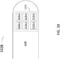
- FIG. 3B is a partial illustration of a distal end 120B of a catheter 102B for multi-frequency imaging, according to some embodiments.
- Distal end 120B includes transducer assembly 122B.
- Transducer assembly 122B includes a plurality of piezo-electric components exemplified by 322B-1, 322B-2, 322B-3, 322B-4, 322B-5, and 322B-6 (collectively referred to hereinafter as 'piezo-electric components 322B').
- 'piezo-electric components 322B' collectively referred to hereinafter as 'piezo-electric components 322B'.
- the specific number of piezo-electric components 322B in assembly 122B is arbitrary and not limiting.
- the specific shape and arrangement of components 322B is also not limiting, depending only in the specific application of a multi-frequency imaging catheter 102.
- a first selected group of components 322B is used for transmitting ultrasound pulses, and a second selected group of components 322B is used for receiving ultrasound echoes.
- the first selected group of components 322B is different from the second selected group of components 322B. Therefore, in some embodiments each of the components 322B-1 through 322B-6 may have a narrow response band, tuned to the specific function of the component (e.g., transmission, reception, or both). For example, component 322B-1 may have a response band including a portion of the transmission band. Likewise, component 322B-2 may have a response band including a portion of the reception band.
- a first selected group of ultrasound pulses provided to the first selected group of components 322B may be centered at a first selected group of frequencies.
- the first selected group of frequencies may include ultrasound frequencies such as 20 MHz, 40 MHz, and 80 MHz.
- a receive amplifier in a processor circuit for a PIM module coupled to transducer 122B has filters with bandwidths selected according to the response band of the second selected group of components 322B.
- radio-frequency (RF) filters in a response amplifier inside a PIM may be centered at a second selected group of frequencies such as 20 MHz, 40 MHz, and 80 MHz.
- RF filters may be included in ASIC 144 at distal end portion 120 of catheter 102, to filter the echo signal in a selected response band.
- the second selected group of frequencies includes harmonic combinations of the first selected group of frequencies.
- a harmonic combination may include integer multiples of a frequency in the first selected group of frequencies.
- transducer assembly 122B may provide a wide response band by using multiple transducer components 322B.
- Each of transducer components 322B may have a narrow response band covering a portion of a transmission band or a portion of a reception band, centered at a selected frequency. Such a configuration may be desirable since piezo-electric components with a narrow response band may provide high response efficiency.
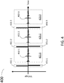
- FIG. 4 is a partial schematic illustration of a transducer voltage 400.
- Transducer voltage 400 includes voltage values across a transducer component in a transducer assembly, as a function of time (e.g., transducer assemblies 122A, 122B in FIGS. 3A , 3B above).
- Transducer voltage 400 includes ultrasound pulse transmit portions 411-1, 411-2, and 411-3, collectively referred to hereinafter as 'transmission portions 411.
- transducer voltage 400 includes ultrasound echo reception portions 421-1, 421-2, and 421-3, collectively referred to hereinafter as 'reception portions 421.' While FIG.
- FIG. 4 illustrates three transmission portions 411 and three reception portions 421, one of ordinary skill will recognize that there is nothing limiting in the number of transmission portions 411, and reception portions 421 that may be used.
- the number of transmission portions 411 may be different from the number of reception portions 421.
- FIG. 4 illustrates each one of transmission portions 411 followed by a reception portion 421. It will be recognized by those with ordinary skill that one or more transmission portions 411 may be provided in sequence, before a reception portion 421 follows. Likewise, a plurality of reception portions 421 may be provided in sequence, after a transmission portion 411.
- Transmission portions 411 include pulses 401-1, 401-2, and 401-3 provided by a pulse transmitter circuit (e.g., pulse transmitter 212, cf. FIG. 2 ) to the transducer assembly. Pulses 401-1 through 401-3 are collectively referred to hereinafter as pulses 401.
- Reception portions 421 include signals 402-1, 402-2, and 402-3 provided by the transducer assembly to an amplifier circuit (e.g., receive amplifier 214, cf. FIG. 2 ). Signals 402-1, 402-2, and 402-3 are referred to hereinafter as ultrasound echo signals 402. Accordingly, ultrasound echo signals 402 may be tissue responses to pulses 401.
- ultrasound echo signals 402 may proceed from different portions of a tissue structure surrounding the transducer assembly.
- ultrasound echo signal 402-3 corresponding to a pulse 401-3 having a high center frequency may proceed from a shallow region of the tissue structure.
- a signal 402 corresponding to a pulse 401 centered at about 80 MHz may proceed from an area of a blood vessel wall proximate to the lumen of the vessel.
- FIG. 5 is a partial schematic illustration of multi-frequency voltage pulses for a transducer component.
- FIG. 5 illustrates voltage pulses 501-1, 501-2, and 501-3, collectively referred hereinafter as voltage pulses 501.
- each of pulses 501 includes a cycle having a period 551-1, 551-2, and 551-3, collectively referred hereinafter as period values 551.
- period 551-1 may be different from period 551-2, thus corresponding to a pulse 501-1 centered at a lower frequency than the center frequency of pulse 501-2.
- period 551-3 may be even shorter than period 551-1, corresponding to an even higher center frequency for pulse 501-3.
- pulses 501 may include any one of a plurality of period values 551.
- each of pulses 501 may be directed to a different transducer component optimized to operate at a specific center frequency.
- transducer component 322B-1 may be designed to operate with maximum efficiency at the center frequency corresponding to period 551-1.
- the specific center frequency associated to a given period 551 may be chosen according to a specific application or need.
- a period 551 may correspond to a frequency of 20 MHz, 40 MHz, 80 MHz, or more.
- one of periods 551 may include a frequency of 10 MHz, or less.
- images having different axial resolution may be obtained.
- an image generated with ultrasound echo signal from pulse 501-1 may have longer penetration depth within the tissue, and lower axial resolution, compared to an image generated from pulse 501-2.
- An image obtained from pulse 501-3 may provide higher axial resolution at a lower penetration depth.
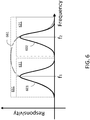
- FIG. 6 is a partial schematic illustration of a transmission band 611, a reception band 621, and a response band 651 in a multi-frequency IVUS imaging system, according to some embodiments.
- response band 651 is a broad band including transmission band 611 and reception band 621.
- Transmission band 611 includes a transmission curve 601 centered at a first frequency f 1
- reception band 621 includes a reception curve 602 centered at a second frequency, f 2 .
- reception band 621 may lay outside of response band 651 of the transducer providing transmission band 611.
- Such embodiments may correspond to a multi-frequency IVUS imaging system using a plurality of transducer components (e.g., transducer 122B, FIG. 3B ).
- transmission band 611 and response band 661 may correspond to transducer component 322B-1.
- reception band 621 from component 322B-2 may be outside of response band 661.
- a multi-frequency IVUS imaging system as disclosed herein may include a PIM coupled to a catheter having a transducer assembly with a transmission band, a reception band, and a response band as illustrated in FIG. 6 (e.g., system 100, PIM 104, catheter 102, and transducer assembly 122, FIG. 1 ).
- the PIM may include a processor circuit to provide a pulse signal to the transducer assembly and receive an ultrasound echo from the signal (e.g., processor circuit 154).
- the processor circuit may include a pulse transmitter circuit having a bandwidth such as transmission band 611 (e.g., pulse transmitter 212).
- the processor circuit may also include a receive amplifier having a bandwidth as reception band 621 (e.g., receive amplifier 214).
- the bandwidth of the pulse transmission circuit and the receive amplifier circuit may be adjusted using RF circuit filtering techniques.
- RF circuit filters may be included in ASIC 144, at distal end portion 120 of catheter 102.
- FIG. 7 is a partial schematic illustration of a signal processing strategy for selecting harmonic components 750 of a signal 705, according to some embodiments.
- an ADC circuit includes a frequency mixer 710 (e.g., ADC 216, FIG. 2 ).
- Mixer 710 combines signal 705 from an amplifier circuit with a local oscillator signal at a harmonic frequency 720.
- the harmonic frequency of the local oscillator is an integer multiple of a center frequency included in a pulse signal for a transducer assembly (e.g., any one of pulses 501, cf. FIG. 5 ).
- Frequency mixer 710 may include a feedback circuit using a phase-lock signal provided by a timing circuit (e.g., clock and timing circuit 200, FIG. 2 ).
- a timing circuit e.g., clock and timing circuit 200, FIG. 2
- the phase lock signal may be included in digitizing signal 226 (cf. FIG. 2 ).
- Harmonic component 750 of signal 705 may thus be transmitted to a reconstruction circuit for imaging (e.g., reconstruction circuit 250).
- FIG. 8 is a flow chart illustrating steps in a method 800 for multi-frequency imaging.
- Method 800 may be performed by a control system (e.g., control system 106) using a processor circuit (e.g., processor circuit 156) and a memory circuit (e.g., memory circuit 157) and/or a PIM (e.g., PIM 104) using a processor circuit (e.g. processor circuit 154) and a memory circuit (e.g., memory circuit 155) based on scan data provided by a transducer assembly (e.g., transducer assembly 122 cf. FIG. 1 ).
- the transducer assembly may be in the distal end of a catheter positioned inside the lumen of a tissue structure (cf. catheter 102, FIG. 1 ).
- Steps in method 800 may be performed by the control system and steps in method 800 may be performed by the PIM.
- a reconstructed image plane in method 800 may be provided to a user in a display (e.g., display 108).
- the reconstructed image may be a 3-dimensional image (3D-image) including a plurality of cross-sectional planes of a tissue structure.
- Step 810 includes generating an ultrasonic signal at a first selected frequency.
- the ultrasonic signal may be generated from a transducer assembly (e.g., transducer assembly 122, cf. FIG. 1 ) in the form of an ultrasound acoustic beam following a path.
- the ultrasound acoustic beam path may be focused, to produce a focal region of high intensity acoustic energy in a target portion of a tissue.
- Step 810 may include providing a voltage pulse to a transducer assembly 122A, B (cf. FIGS. 3A , B ). Accordingly, a voltage pulse maybe provided by the PIM to transducer assemblies 122A, B for a pre-selected period of time.
- a voltage pulse for transducer assemblies 122A, B may be provided in a series of pulses such as pulses 401, or pulses 501 produced at a preselected center frequency (cf. FIGS. 4 and 5 ).
- Step 810 may include generating a plurality of pulses at a first plurality of center frequencies.
- the first plurality of center frequencies may include different center frequencies.
- Step 820 includes scanning the ultrasonic signal in a predetermined pattern about the interior wall of a structure.
- Step 820 may include sweeping the ultrasonic signal continuously in a helicoid pattern about an interior wall of a blood vessel.
- Step 820 is accomplished by rotating the transducer or rotating a reflective surface which deflects the signal from the transducer within a catheter.
- the catheter may remain substantially stationary while the transducer is rotated and the acoustic signal is swept radially around the LA of the catheter.
- Step 820 includes a stationary transducer assembly having multiple components around a circumference (e.g., transducers 322B, cf. FIG. 3B ).
- a stationary transducer assembly having multiple components around a circumference (e.g., transducers 322B, cf. FIG. 3B ).
- Step 830 includes receiving an ultrasonic echo from the interior wall of the structure at a second selected frequency.
- Step 830 may be performed using the transducer assembly of step 810.
- the transducer assembly may be configured to couple the voltage signal out of a surrounding tissue structure into a processor circuit (e.g., processor circuit 154 in PIM 104).
- Step 830 maybe performed during a period of time between two voltage pulses 401 generating acoustic signals according to step 810 (cf. FIG. 4 ).
- a voltage signal travels from the processor circuit in the PIM to the transducer assembly along a catheter (e.g., catheter 102, FIG. 1 ) at a first selected frequency.
- a voltage signal travels from the transducer assembly to the processor circuit in the PIM.
- the voltage signal may include the second selected frequency.
- the second selected frequency may be centered at a harmonic frequency of the first frequency.
- the second selected frequency includes the first plurality of selected frequencies of step 810.
- the second selected frequency may include a sum of two different frequencies from the first plurality of selected frequencies in step 810.
- the second selected frequency may include an integer multiple of either one of the frequencies from the first plurality of selected frequencies.
- Step 840 includes amplifying the ultrasonic echo in the processor circuit.
- Step 840 may include filtering the ultrasonic echo signal using electronic filters having a band-pass including the second selected frequency. Accordingly, a portion of step 840 may be performed by an ASIC circuit at a distal end of the catheter (e.g., ASIC 144 in FIG. 1B ).
- Step 850 includes producing an image from the ultrasonic echo. Step 850 may be performed partially by the PIM. For example, step 850 may be partially performed by a reconstruction circuit (e.g., reconstruction circuit 250, FIG. 2 ).
- Step 850 includes producing a 2-dimensional image (2D-image) of a cross section of the blood vessel wall.
- Step 850 includes producing a 3-dimensional image (3D-image) of the blood vessel wall from a plurality of 2D-images.
- Step 860 includes classifying the image from the amplified ultrasonic echo. Step 860 may be performed by the processor circuit and the memory circuit in the control system. Step 860 is performed by processor circuit 156 executing commands, retrieving and storing data, the commands and the data being stored in memory circuit 157. The commands executed by processor circuit 156 in control system 106 maybe included in an image characterization code stored in memory circuit 157.
- the image characterization code may render a characterized tissue component map.
- the image characterization application may perform a spectral analysis of ultrasound echo information for a vessel cross-section.
- different plaque components may be determined and distinguished in the characterized tissue component map.
- the characterization application mayuse a classification criterion including a rule based upon a location of a confluence of necrotic core within the vessel cross-section in relation to a border between the lumen and a plaque.
- a classification criterion may include a rule, based upon a location, in relation to a lumen-plaque border, of confluent necrotic core within the vessel cross-section; and rendering, in response to the classification, a plaque classification associated with the vessel cross-section.
- a classification criterion may use the thickness of fibrous cap to determine the vulnerability of a plaque, and the likelihood of plaque rupture and thrombosis.
- Image characterization applications as used in step 860 may be as disclosed in US PAT. No. 7,627,156 entitled “Automated lesion analysis based upon automatic plaque characterization according to a classification criterion," US PAT. No. 7,175,597 entitled “Non-Invasive Tissue Characterization System and Method,” and US PAT. No. 6,200,268 entitled “Vascular Plaque Characterization,”.
- FIG. 9 is a flow chart illustrating steps in a method 900 for multi-frequency imaging.
- Method 900 may be performed partially by system 100.
- Method 900 may be performed by a control system (e.g., control system 106) using a processor circuit (e.g., processor circuit 156) and a memory circuit (e.g., memory circuit 157) and/or a PIM (e.g., PIM 104) using a processor circuit (e.g. processor circuit 154) and a memory circuit (e.g., memory circuit 155) based on scan data provided by a transducer assembly (e.g., transducer assembly 122 cf. FIG. 1 ).
- a control system e.g., control system 106
- a processor circuit e.g., processor circuit 156
- a memory circuit e.g., memory circuit 157
- PIM e.g., PIM 104
- a transducer assembly e.g., transducer assembly 122 cf
- the transducer assembly may be positioned in the distal end of a catheter positioned inside the lumen of a tissue structure (cf. catheter 102, FIG. 1 ). Steps in method 900 may be performed by the control system and steps in method 900 may be performed by the PIM.
- a reconstructed image plane in method 900 may be provided to an external operator in display 108.
- the external operator makes a decision of whether to excise a portion of the stenosed segment of the blood vessel using a recanalization tool, based on the reconstructed image plane on display 108.
- the recanalization tool maybe a physical instrument having a sharp end.
- the recanalization tool may be a laser beam susceptible of being directed to a point in the blood vessel and ablate a tissue portion.
- the recanalization tool may include an abrasive surface that may be rubbed against the target tissue.
- Step 910 includes generating an ultrasonic signal at a first plurality of frequencies.
- Step 910 may further include positioning catheter 102 with its LA substantially aligned with the blood vessel, inside the lumen portion of the blood vessel.
- Step 920 includes scanning the ultrasonic signal in a predetermined pattern about the interior wall of a structure.
- the interior wall of a structure is the interior portion of a blood vessel wall including a region of stenosis.
- the region of stenosis may include a plaque having a calcified portion, a lipid pool, and a necrotic core adjacent to the lipid pool.
- Step 930 includes receiving an ultrasonic echo from the interior wall of the structure, within a reception band of frequencies.
- a reception band of frequencies in step 930 may include the first plurality of frequencies.
- the reception band of frequencies may include harmonic combinations of the first plurality of frequencies. Harmonic combinations of the first plurality of frequencies may include integer multiples of either of the frequencies in the first plurality of frequencies. Furthermore, harmonic combinations of the first plurality of frequencies may include sums of any number of frequencies in the first plurality of frequencies.
- Step 940 includes amplifying the ultrasonic echo in a processor circuit. Step 940 may be as step 840 described in detail above, in relation to method 800.
- Step 950 includes producing a plurality of images from the amplified ultrasonic echo. Accordingly, step 950 may include producing an image for each of the frequencies within the reception band of frequencies in step 930. Producing each image in step 950 maybe as described in detail above, with relation to step 850, in method 800.
- Step 960 includes combining the plurality of images from step 950 to form an image.
- Step 950 may include combining a portion of a first image obtained with a high frequency ultrasound echo with a portion of a second image obtained with a low frequency ultrasound echo.
- the portion of the first image may be a shallower portion of the tissue structure
- the portion of the second image may be a deeper portion of the tissue structure.
- the portion of the second image may filter out blood speckle artifacts typically encountered in high frequency ultrasound signal, such as used for the first image.
- a first portion of an image of a blood vessel obtained at 80 MHz may include the endothelium of the blood vessel, including the border between the blood vessel wall and the lumen.
- a second portion of an image of a blood vessel obtained at 20 MHz may include portions of necrotic tissue in a plaque, macrophage cells, and muscle cells deeper into the blood vessel wall.
- Step 970 includes classifying the image obtained in step 960.
- Step 970 may be performed by processor circuit 156 and memory circuit 157 in control system 106.
- Step 970 is performed by processor circuit 156 executing commands, retrieving and storing data, the commands and the data being stored in memory circuit 157.
- the commands executed by processor circuit 156 in control system 106 may be included in an image characterization code stored in memory circuit 157.
- the image characterization code may render a characterized tissue component map.
- the image characterization application is able to perform a spectral analysis of ultrasound echo information for a blood vessel cross-section.
- different plaque components may be determined and distinguished in the characterized tissue map.
- the characterization application may use a classification criterion including a rule based upon a location of a confluence of necrotic core within the vessel cross-section in relation to a border between the lumen and a plaque.
- a classification criterion may use the thickness of a fibrous cap to determine the vulnerability of a plaque, and the likelihood of plaque rupture and thrombosis. For example, a plaque may be classified as 'vulnerable' to rupture, based on the size, configuration, and nature of its components.
- a component of a plaque within a blood vessel may be a fibrous cap and a necrotic core.
- a component of a plaque within a vessel may include fat cell tissue and macrophage cells.
- the nature of a component of a plaque within a vessel may include substances such as elastin, collagen and cholesterol.
- the viscoelastic properties of the substances and the configuration of the different components included in a plaque within a vessel provide a differentiated acoustic response to the ultrasonic signals in step 910.
- interaction of the blood vessel wall with ultrasonic signals in step 910 may produce an image that clearly differentiates the components of the plaque, their nature, and their configuration (size and shape).
Landscapes
- Health & Medical Sciences (AREA)
- Life Sciences & Earth Sciences (AREA)
- Engineering & Computer Science (AREA)
- Physics & Mathematics (AREA)
- Molecular Biology (AREA)
- General Health & Medical Sciences (AREA)
- Pathology (AREA)
- Radiology & Medical Imaging (AREA)
- Biophysics (AREA)
- Biomedical Technology (AREA)
- Heart & Thoracic Surgery (AREA)
- Medical Informatics (AREA)
- Veterinary Medicine (AREA)
- Surgery (AREA)
- Animal Behavior & Ethology (AREA)
- Nuclear Medicine, Radiotherapy & Molecular Imaging (AREA)
- Public Health (AREA)
- Radar, Positioning & Navigation (AREA)
- Remote Sensing (AREA)
- Computer Networks & Wireless Communication (AREA)
- Gynecology & Obstetrics (AREA)
- General Physics & Mathematics (AREA)
- Acoustics & Sound (AREA)
- Computer Vision & Pattern Recognition (AREA)
- Nonlinear Science (AREA)
- Vascular Medicine (AREA)
- Ultra Sonic Daignosis Equipment (AREA)
Claims (12)
- Système d'imagerie ultrasonique intravasculaire (IVUS) (100) pour imager un volume au sein d'un patient, le système d'imagerie IVUS comprenant :un module d'interface (104) comprenant un circuit de traitement (154) et un cathéter IVUS (102) comprenant une pluralité de composants transducteurs piézoélectriques à l'extrémité distale, ladite pluralité ayant un premier composant transducteur pour générer (810) un signal ultrasonique à une première fréquence sélectionnée et un second composant transducteur pour recevoir (830) un écho ultrasonique (224) à une seconde fréquence sélectionnée, dans lequel la seconde fréquence est une harmonique de la première fréquence ;dans lequel le second composant transducteur a une bande de réponse incluant une partie d'une bande de réception ;dans lequel le cathéter IVUS est configuré pour diriger le signal ultrasonique sur une tache dans le volume au sein du patient et balayer (820) la tache selon un motif prédéterminé autour de la paroi du volume au sein du patient ;dans lequel le second composant transducteur est configuré pour convertir l'écho ultrasonique reçu en un signal de tension incluant la seconde fréquence sélectionnée ;dans lequel le module d'interface (104) comprend un amplificateur de réception (214) ayant des filtres avec des largeurs de bande produisant ladite bande de réception sélectionnée selon ladite bande de réponse et configuré pour amplifier (840) le signal de tension avec un circuit de traitement (154) ; etdans lequel le système d'imagerie IVUS est configuré pour fournir (850) une image du volume au sein du patient à partir du signal de tension amplifié.
- Système d'imagerie IVUS selon la revendication 1, dans lequel le cathéter IVUS comprend en outre un circuit intégré spécifique à l'application (ASIC) positionné à proximité du premier composant transducteur et du second composant transducteur et dans lequel la génération du signal ultrasonique et la réception de l'écho ultrasonique sont en partie effectuées par l'ASIC.
- Système d'imagerie IVUS selon la revendication 1 ou la revendication 2, dans lequel le premier composant transducteur et le second composant transducteur comprennent un matériau polymère pour transducteur.
- Système d'imagerie IVUS selon l'une quelconque des revendications 1 à 3, dans lequel le premier composant transducteur comprend une première pluralité de composants transducteurs et le second composant transducteur comprend une seconde pluralité de composants transducteurs.
- Système d'imagerie IVUS selon la revendication 4, dans lequel la première fréquence sélectionnée comprend une première pluralité de fréquences, chacune de la première pluralité de fréquences étant associée à chacun de la première pluralité de composants transducteurs.
- Système d'imagerie IVUS selon la revendication 5, dans lequel la seconde fréquence sélectionnée comprend une seconde pluralité de fréquences, chacune de la seconde pluralité de fréquences étant associée à chacun de la seconde pluralité de composants transducteurs.
- Système d'imagerie IVUS selon la revendication 6, dans lequel le système d'imagerie IVUS est configuré pour fournir (950) une pluralité d'images du volume au sein du patient, la pluralité d'images comprenant une image pour chacune des fréquences de la seconde pluralité de fréquences.
- Système d'imagerie IVUS selon la revendication 7, dans lequel le système d'imagerie IVUS est configuré pour combiner au moins une première image volumique associée à une première fréquence et une seconde image volumique associée à une seconde fréquence de la seconde pluralité de fréquences pour former une image volumique combinée.
- Système d'imagerie IVUS selon la revendication 8, dans lequel le système d'imagerie IVUS est configuré pour combiner une partie peu profonde du volume à une fréquence plus élevée parmi les premières et secondes fréquences avec une partie profonde du volume à une fréquence plus faible parmi les premières et secondes fréquences.
- Système d'imagerie IVUS selon la revendication 9, dans lequel le système d'imagerie IVUS est configuré pour séparer par filtration un signal de mouchetures de sang de l'image volumique combinée.
- Système d'imagerie IVUS selon l'une quelconque des revendications 7 à 10, dans lequel le PIM est configuré pour extraire une composante de fréquence de la tension en utilisant un circuit mélangeur de fréquences dans le circuit de traitement.
- Système d'imagerie IVUS selon la revendication 11, dans lequel la composante de fréquence est une combinaison harmonique de certaines quelconques des fréquences de la première pluralité de fréquences.
Applications Claiming Priority (2)
| Application Number | Priority Date | Filing Date | Title |
|---|---|---|---|
| US201261740822P | 2012-12-21 | 2012-12-21 | |
| PCT/US2013/076195 WO2014100217A1 (fr) | 2012-12-21 | 2013-12-18 | Procédé pour imagerie multifréquence utilisant des sorties de transducteur de largeur de bande élevée |
Publications (3)
| Publication Number | Publication Date |
|---|---|
| EP2934333A1 EP2934333A1 (fr) | 2015-10-28 |
| EP2934333A4 EP2934333A4 (fr) | 2016-07-20 |
| EP2934333B1 true EP2934333B1 (fr) | 2019-05-15 |
Family
ID=50975438
Family Applications (1)
| Application Number | Title | Priority Date | Filing Date |
|---|---|---|---|
| EP13864905.8A Active EP2934333B1 (fr) | 2012-12-21 | 2013-12-18 | Procédé pour imagerie multifréquence utilisant des sorties de transducteur de largeur de bande élevée |
Country Status (5)
| Country | Link |
|---|---|
| US (1) | US20140180108A1 (fr) |
| EP (1) | EP2934333B1 (fr) |
| JP (1) | JP2016501634A (fr) |
| CA (1) | CA2895802A1 (fr) |
| WO (1) | WO2014100217A1 (fr) |
Families Citing this family (10)
| Publication number | Priority date | Publication date | Assignee | Title |
|---|---|---|---|---|
| US9808222B2 (en) | 2009-10-12 | 2017-11-07 | Acist Medical Systems, Inc. | Intravascular ultrasound system for co-registered imaging |
| CA2835899C (fr) | 2011-05-10 | 2019-04-16 | Edison Welding Institute, Inc. | Systeme d'inspection de soudure par points a commande de phase a matrice tridimensionnelle |
| US9037419B2 (en) | 2011-05-10 | 2015-05-19 | Edison Welding Institute, Inc. | Portable matrix phased array spot weld inspection system |
| US10542954B2 (en) * | 2014-07-14 | 2020-01-28 | Volcano Corporation | Devices, systems, and methods for improved accuracy model of vessel anatomy |
| US10653393B2 (en) * | 2015-10-08 | 2020-05-19 | Acist Medical Systems, Inc. | Intravascular ultrasound imaging with frequency selective imaging methods and systems |
| US10909661B2 (en) | 2015-10-08 | 2021-02-02 | Acist Medical Systems, Inc. | Systems and methods to reduce near-field artifacts |
| EP3537984B1 (fr) * | 2016-11-11 | 2024-01-10 | Koninklijke Philips N.V. | Dispositif d'imagerie intraluminale sans fil et dispositifs, systèmes et procédés associés |
| CN111065340B (zh) * | 2017-09-28 | 2022-09-20 | 波士顿科学国际有限公司 | 基于频率调节沿血管内超声成像系统的信号路径的系统和方法 |
| CN109498062A (zh) * | 2018-12-29 | 2019-03-22 | 深圳市中科微光医疗器械技术有限公司 | 一种多频可调的血管内超声成像系统及方法 |
| US11024034B2 (en) | 2019-07-02 | 2021-06-01 | Acist Medical Systems, Inc. | Image segmentation confidence determination |
Citations (4)
| Publication number | Priority date | Publication date | Assignee | Title |
|---|---|---|---|---|
| US20080114245A1 (en) * | 2006-11-10 | 2008-05-15 | Randall Kevin S | Transducer array imaging system |
| US20100174190A1 (en) * | 2009-01-08 | 2010-07-08 | Volcano Corporation | System and method for equalizing received intravascular ultrasound echo signals |
| US20100241005A1 (en) * | 2008-10-03 | 2010-09-23 | Mirabilis Medica, Inc. | Office-based system for treating uterine fibroids or other tissues with hifu |
| WO2012144243A1 (fr) * | 2011-04-20 | 2012-10-26 | 株式会社 日立メディコ | Appareil d'imagerie à ultrasons |
Family Cites Families (20)
| Publication number | Priority date | Publication date | Assignee | Title |
|---|---|---|---|---|
| US5243988A (en) | 1991-03-13 | 1993-09-14 | Scimed Life Systems, Inc. | Intravascular imaging apparatus and methods for use and manufacture |
| DE69333482T2 (de) | 1992-02-21 | 2005-03-24 | Boston Scientific Ltd., Barbados | Katheter zur Bilderzeugung mittels Ultraschall |
| US6248073B1 (en) * | 1995-06-29 | 2001-06-19 | Teratech Corporation | Ultrasound scan conversion with spatial dithering |
| US6132374A (en) * | 1997-08-01 | 2000-10-17 | Acuson Corporation | Ultrasonic imaging method and system |
| US6050943A (en) * | 1997-10-14 | 2000-04-18 | Guided Therapy Systems, Inc. | Imaging, therapy, and temperature monitoring ultrasonic system |
| JP4574802B2 (ja) * | 1999-06-03 | 2010-11-04 | 東芝医用システムエンジニアリング株式会社 | 超音波診断装置 |
| US9402601B1 (en) * | 1999-06-22 | 2016-08-02 | Teratech Corporation | Methods for controlling an ultrasound imaging procedure and providing ultrasound images to an external non-ultrasound application via a network |
| US6200268B1 (en) | 1999-09-10 | 2001-03-13 | The Cleveland Clinic Foundation | Vascular plaque characterization |
| US6440075B1 (en) * | 2000-10-02 | 2002-08-27 | Koninklijke Philips Electronics N.V. | Ultrasonic diagnostic imaging of nonlinearly intermodulated and harmonic frequency components |
| JP4067964B2 (ja) | 2000-12-01 | 2008-03-26 | ザ クリーブランド クリニック ファウンデーション | 小型超音波トランスデューサ |
| US7175597B2 (en) | 2003-02-03 | 2007-02-13 | Cleveland Clinic Foundation | Non-invasive tissue characterization system and method |
| GB2445322B (en) * | 2004-08-13 | 2008-08-06 | Stichting Tech Wetenschapp | Intravasular ultrasound techniques |
| US20060253028A1 (en) * | 2005-04-20 | 2006-11-09 | Scimed Life Systems, Inc. | Multiple transducer configurations for medical ultrasound imaging |
| US7627156B2 (en) * | 2006-03-22 | 2009-12-01 | Volcano Corporation | Automated lesion analysis based upon automatic plaque characterization according to a classification criterion |
| US8330332B2 (en) * | 2006-07-24 | 2012-12-11 | Koninklijke Philips Electronics N.V. | Ultrasound transducer featuring a pitch independent interposer and method of making the same |
| US8403856B2 (en) * | 2009-03-11 | 2013-03-26 | Volcano Corporation | Rotational intravascular ultrasound probe with an active spinning element |
| JP5754022B2 (ja) * | 2009-12-29 | 2015-07-22 | ボストン サイエンティフィック サイムド,インコーポレイテッドBoston Scientific Scimed,Inc. | 血管内超音波撮像システムを用いた患者組織の多重周波数撮像のためのシステム |
| JP5656520B2 (ja) * | 2010-09-06 | 2015-01-21 | 富士フイルム株式会社 | 超音波診断装置 |
| EP2671093B1 (fr) * | 2011-01-31 | 2019-01-16 | Sunnybrook Health Sciences Centre | Sonde à ultrasons comprenant des transducteurs à ultrasons pouvant être adressés sur un canal électrique commun |
| US20140066768A1 (en) * | 2012-08-30 | 2014-03-06 | Siemens Medical Solutions Usa, Inc. | Frequency Distribution in Harmonic Ultrasound Imaging |
-
2013
- 2013-12-18 CA CA2895802A patent/CA2895802A1/fr not_active Abandoned
- 2013-12-18 EP EP13864905.8A patent/EP2934333B1/fr active Active
- 2013-12-18 WO PCT/US2013/076195 patent/WO2014100217A1/fr active Application Filing
- 2013-12-18 JP JP2015549641A patent/JP2016501634A/ja active Pending
- 2013-12-19 US US14/135,397 patent/US20140180108A1/en not_active Abandoned
Patent Citations (4)
| Publication number | Priority date | Publication date | Assignee | Title |
|---|---|---|---|---|
| US20080114245A1 (en) * | 2006-11-10 | 2008-05-15 | Randall Kevin S | Transducer array imaging system |
| US20100241005A1 (en) * | 2008-10-03 | 2010-09-23 | Mirabilis Medica, Inc. | Office-based system for treating uterine fibroids or other tissues with hifu |
| US20100174190A1 (en) * | 2009-01-08 | 2010-07-08 | Volcano Corporation | System and method for equalizing received intravascular ultrasound echo signals |
| WO2012144243A1 (fr) * | 2011-04-20 | 2012-10-26 | 株式会社 日立メディコ | Appareil d'imagerie à ultrasons |
Also Published As
| Publication number | Publication date |
|---|---|
| JP2016501634A (ja) | 2016-01-21 |
| WO2014100217A1 (fr) | 2014-06-26 |
| US20140180108A1 (en) | 2014-06-26 |
| EP2934333A4 (fr) | 2016-07-20 |
| CA2895802A1 (fr) | 2014-06-26 |
| EP2934333A1 (fr) | 2015-10-28 |
Similar Documents
| Publication | Publication Date | Title |
|---|---|---|
| US11596389B2 (en) | Method for multi-frequency imaging and composite image display using high-bandwidth transducer outputs | |
| EP2934333B1 (fr) | Procédé pour imagerie multifréquence utilisant des sorties de transducteur de largeur de bande élevée | |
| US11013491B2 (en) | Method for focused acoustic computed tomography (FACT) | |
| US11000185B2 (en) | Devices, systems, and methods for visualizing an occluded vessel | |
| JP6445076B2 (ja) | 共通電気チャネル上で処理可能な超音波トランスデューサを有する超音波プローブ | |
| US9486143B2 (en) | Intravascular forward imaging device | |
| EP2637566B1 (fr) | Systèmes et programme informatique de fabrication et d'utilisation de transducteurs rotatifs pour une imagerie simultanée de débit de sang et de tissu | |
| JP6211599B2 (ja) | 撮像及び血流測定のための超音波カテーテル | |
| CN108272469B (zh) | 一种双频率血管内超声成像探头 | |
| US20120172698A1 (en) | Imaging system | |
| JP7304344B2 (ja) | 無線充電を使用する無線デジタル患者インタフェースモジュール | |
| EP3697315B1 (fr) | Module d'interface patient rotatif numérique | |
| CA2815644A1 (fr) | Systemes et procedes de fabrication et d'utilisation de transducteurs rotatifs pour une imagerie simultanee de debit de sang et de tissu |
Legal Events
| Date | Code | Title | Description |
|---|---|---|---|
| PUAI | Public reference made under article 153(3) epc to a published international application that has entered the european phase |
Free format text: ORIGINAL CODE: 0009012 |
|
| 17P | Request for examination filed |
Effective date: 20150529 |
|
| AK | Designated contracting states |
Kind code of ref document: A1 Designated state(s): AL AT BE BG CH CY CZ DE DK EE ES FI FR GB GR HR HU IE IS IT LI LT LU LV MC MK MT NL NO PL PT RO RS SE SI SK SM TR |
|
| AX | Request for extension of the european patent |
Extension state: BA ME |
|
| DAX | Request for extension of the european patent (deleted) | ||
| A4 | Supplementary search report drawn up and despatched |
Effective date: 20160620 |
|
| RIC1 | Information provided on ipc code assigned before grant |
Ipc: A61B 8/12 20060101AFI20160614BHEP |
|
| STAA | Information on the status of an ep patent application or granted ep patent |
Free format text: STATUS: EXAMINATION IS IN PROGRESS |
|
| 17Q | First examination report despatched |
Effective date: 20181001 |
|
| REG | Reference to a national code |
Ref country code: DE Ref legal event code: R079 Ref document number: 602013055584 Country of ref document: DE Free format text: PREVIOUS MAIN CLASS: A61B0008120000 Ipc: G01S0015890000 |
|
| GRAP | Despatch of communication of intention to grant a patent |
Free format text: ORIGINAL CODE: EPIDOSNIGR1 |
|
| STAA | Information on the status of an ep patent application or granted ep patent |
Free format text: STATUS: GRANT OF PATENT IS INTENDED |
|
| RIC1 | Information provided on ipc code assigned before grant |
Ipc: A61B 8/00 20060101ALI20181120BHEP Ipc: A61B 8/08 20060101ALI20181120BHEP Ipc: G01S 15/89 20060101AFI20181120BHEP |
|
| INTG | Intention to grant announced |
Effective date: 20181217 |
|
| GRAS | Grant fee paid |
Free format text: ORIGINAL CODE: EPIDOSNIGR3 |
|
| GRAA | (expected) grant |
Free format text: ORIGINAL CODE: 0009210 |
|
| STAA | Information on the status of an ep patent application or granted ep patent |
Free format text: STATUS: THE PATENT HAS BEEN GRANTED |
|
| AK | Designated contracting states |
Kind code of ref document: B1 Designated state(s): AL AT BE BG CH CY CZ DE DK EE ES FI FR GB GR HR HU IE IS IT LI LT LU LV MC MK MT NL NO PL PT RO RS SE SI SK SM TR |
|
| REG | Reference to a national code |
Ref country code: CH Ref legal event code: EP |
|
| REG | Reference to a national code |
Ref country code: DE Ref legal event code: R096 Ref document number: 602013055584 Country of ref document: DE |
|
| REG | Reference to a national code |
Ref country code: IE Ref legal event code: FG4D |
|
| REG | Reference to a national code |
Ref country code: NL Ref legal event code: MP Effective date: 20190515 |
|
| REG | Reference to a national code |
Ref country code: LT Ref legal event code: MG4D |
|
| PG25 | Lapsed in a contracting state [announced via postgrant information from national office to epo] |
Ref country code: LT Free format text: LAPSE BECAUSE OF FAILURE TO SUBMIT A TRANSLATION OF THE DESCRIPTION OR TO PAY THE FEE WITHIN THE PRESCRIBED TIME-LIMIT Effective date: 20190515 Ref country code: HR Free format text: LAPSE BECAUSE OF FAILURE TO SUBMIT A TRANSLATION OF THE DESCRIPTION OR TO PAY THE FEE WITHIN THE PRESCRIBED TIME-LIMIT Effective date: 20190515 Ref country code: ES Free format text: LAPSE BECAUSE OF FAILURE TO SUBMIT A TRANSLATION OF THE DESCRIPTION OR TO PAY THE FEE WITHIN THE PRESCRIBED TIME-LIMIT Effective date: 20190515 Ref country code: NL Free format text: LAPSE BECAUSE OF FAILURE TO SUBMIT A TRANSLATION OF THE DESCRIPTION OR TO PAY THE FEE WITHIN THE PRESCRIBED TIME-LIMIT Effective date: 20190515 Ref country code: PT Free format text: LAPSE BECAUSE OF FAILURE TO SUBMIT A TRANSLATION OF THE DESCRIPTION OR TO PAY THE FEE WITHIN THE PRESCRIBED TIME-LIMIT Effective date: 20190915 Ref country code: NO Free format text: LAPSE BECAUSE OF FAILURE TO SUBMIT A TRANSLATION OF THE DESCRIPTION OR TO PAY THE FEE WITHIN THE PRESCRIBED TIME-LIMIT Effective date: 20190815 Ref country code: SE Free format text: LAPSE BECAUSE OF FAILURE TO SUBMIT A TRANSLATION OF THE DESCRIPTION OR TO PAY THE FEE WITHIN THE PRESCRIBED TIME-LIMIT Effective date: 20190515 Ref country code: AL Free format text: LAPSE BECAUSE OF FAILURE TO SUBMIT A TRANSLATION OF THE DESCRIPTION OR TO PAY THE FEE WITHIN THE PRESCRIBED TIME-LIMIT Effective date: 20190515 Ref country code: FI Free format text: LAPSE BECAUSE OF FAILURE TO SUBMIT A TRANSLATION OF THE DESCRIPTION OR TO PAY THE FEE WITHIN THE PRESCRIBED TIME-LIMIT Effective date: 20190515 |
|
| PG25 | Lapsed in a contracting state [announced via postgrant information from national office to epo] |
Ref country code: BG Free format text: LAPSE BECAUSE OF FAILURE TO SUBMIT A TRANSLATION OF THE DESCRIPTION OR TO PAY THE FEE WITHIN THE PRESCRIBED TIME-LIMIT Effective date: 20190815 Ref country code: GR Free format text: LAPSE BECAUSE OF FAILURE TO SUBMIT A TRANSLATION OF THE DESCRIPTION OR TO PAY THE FEE WITHIN THE PRESCRIBED TIME-LIMIT Effective date: 20190816 Ref country code: LV Free format text: LAPSE BECAUSE OF FAILURE TO SUBMIT A TRANSLATION OF THE DESCRIPTION OR TO PAY THE FEE WITHIN THE PRESCRIBED TIME-LIMIT Effective date: 20190515 Ref country code: RS Free format text: LAPSE BECAUSE OF FAILURE TO SUBMIT A TRANSLATION OF THE DESCRIPTION OR TO PAY THE FEE WITHIN THE PRESCRIBED TIME-LIMIT Effective date: 20190515 |
|
| REG | Reference to a national code |
Ref country code: AT Ref legal event code: MK05 Ref document number: 1134090 Country of ref document: AT Kind code of ref document: T Effective date: 20190515 |
|
| PG25 | Lapsed in a contracting state [announced via postgrant information from national office to epo] |
Ref country code: EE Free format text: LAPSE BECAUSE OF FAILURE TO SUBMIT A TRANSLATION OF THE DESCRIPTION OR TO PAY THE FEE WITHIN THE PRESCRIBED TIME-LIMIT Effective date: 20190515 Ref country code: SK Free format text: LAPSE BECAUSE OF FAILURE TO SUBMIT A TRANSLATION OF THE DESCRIPTION OR TO PAY THE FEE WITHIN THE PRESCRIBED TIME-LIMIT Effective date: 20190515 Ref country code: CZ Free format text: LAPSE BECAUSE OF FAILURE TO SUBMIT A TRANSLATION OF THE DESCRIPTION OR TO PAY THE FEE WITHIN THE PRESCRIBED TIME-LIMIT Effective date: 20190515 Ref country code: RO Free format text: LAPSE BECAUSE OF FAILURE TO SUBMIT A TRANSLATION OF THE DESCRIPTION OR TO PAY THE FEE WITHIN THE PRESCRIBED TIME-LIMIT Effective date: 20190515 Ref country code: AT Free format text: LAPSE BECAUSE OF FAILURE TO SUBMIT A TRANSLATION OF THE DESCRIPTION OR TO PAY THE FEE WITHIN THE PRESCRIBED TIME-LIMIT Effective date: 20190515 Ref country code: DK Free format text: LAPSE BECAUSE OF FAILURE TO SUBMIT A TRANSLATION OF THE DESCRIPTION OR TO PAY THE FEE WITHIN THE PRESCRIBED TIME-LIMIT Effective date: 20190515 |
|
| REG | Reference to a national code |
Ref country code: DE Ref legal event code: R097 Ref document number: 602013055584 Country of ref document: DE |
|
| PG25 | Lapsed in a contracting state [announced via postgrant information from national office to epo] |
Ref country code: SM Free format text: LAPSE BECAUSE OF FAILURE TO SUBMIT A TRANSLATION OF THE DESCRIPTION OR TO PAY THE FEE WITHIN THE PRESCRIBED TIME-LIMIT Effective date: 20190515 Ref country code: IT Free format text: LAPSE BECAUSE OF FAILURE TO SUBMIT A TRANSLATION OF THE DESCRIPTION OR TO PAY THE FEE WITHIN THE PRESCRIBED TIME-LIMIT Effective date: 20190515 |
|
| PLBE | No opposition filed within time limit |
Free format text: ORIGINAL CODE: 0009261 |
|
| STAA | Information on the status of an ep patent application or granted ep patent |
Free format text: STATUS: NO OPPOSITION FILED WITHIN TIME LIMIT |
|
| PG25 | Lapsed in a contracting state [announced via postgrant information from national office to epo] |
Ref country code: TR Free format text: LAPSE BECAUSE OF FAILURE TO SUBMIT A TRANSLATION OF THE DESCRIPTION OR TO PAY THE FEE WITHIN THE PRESCRIBED TIME-LIMIT Effective date: 20190515 |
|
| 26N | No opposition filed |
Effective date: 20200218 |
|
| PG25 | Lapsed in a contracting state [announced via postgrant information from national office to epo] |
Ref country code: PL Free format text: LAPSE BECAUSE OF FAILURE TO SUBMIT A TRANSLATION OF THE DESCRIPTION OR TO PAY THE FEE WITHIN THE PRESCRIBED TIME-LIMIT Effective date: 20190515 |
|
| PG25 | Lapsed in a contracting state [announced via postgrant information from national office to epo] |
Ref country code: SI Free format text: LAPSE BECAUSE OF FAILURE TO SUBMIT A TRANSLATION OF THE DESCRIPTION OR TO PAY THE FEE WITHIN THE PRESCRIBED TIME-LIMIT Effective date: 20190515 |
|
| REG | Reference to a national code |
Ref country code: CH Ref legal event code: PL |
|
| REG | Reference to a national code |
Ref country code: BE Ref legal event code: MM Effective date: 20191231 |
|
| PG25 | Lapsed in a contracting state [announced via postgrant information from national office to epo] |
Ref country code: MC Free format text: LAPSE BECAUSE OF FAILURE TO SUBMIT A TRANSLATION OF THE DESCRIPTION OR TO PAY THE FEE WITHIN THE PRESCRIBED TIME-LIMIT Effective date: 20190515 |
|
| PG25 | Lapsed in a contracting state [announced via postgrant information from national office to epo] |
Ref country code: IE Free format text: LAPSE BECAUSE OF NON-PAYMENT OF DUE FEES Effective date: 20191218 Ref country code: FR Free format text: LAPSE BECAUSE OF NON-PAYMENT OF DUE FEES Effective date: 20191231 Ref country code: LU Free format text: LAPSE BECAUSE OF NON-PAYMENT OF DUE FEES Effective date: 20191218 |
|
| PG25 | Lapsed in a contracting state [announced via postgrant information from national office to epo] |
Ref country code: LI Free format text: LAPSE BECAUSE OF NON-PAYMENT OF DUE FEES Effective date: 20191231 Ref country code: CH Free format text: LAPSE BECAUSE OF NON-PAYMENT OF DUE FEES Effective date: 20191231 Ref country code: BE Free format text: LAPSE BECAUSE OF NON-PAYMENT OF DUE FEES Effective date: 20191231 |
|
| PG25 | Lapsed in a contracting state [announced via postgrant information from national office to epo] |
Ref country code: CY Free format text: LAPSE BECAUSE OF FAILURE TO SUBMIT A TRANSLATION OF THE DESCRIPTION OR TO PAY THE FEE WITHIN THE PRESCRIBED TIME-LIMIT Effective date: 20190515 |
|
| PG25 | Lapsed in a contracting state [announced via postgrant information from national office to epo] |
Ref country code: IS Free format text: LAPSE BECAUSE OF FAILURE TO SUBMIT A TRANSLATION OF THE DESCRIPTION OR TO PAY THE FEE WITHIN THE PRESCRIBED TIME-LIMIT Effective date: 20190915 |
|
| PG25 | Lapsed in a contracting state [announced via postgrant information from national office to epo] |
Ref country code: HU Free format text: LAPSE BECAUSE OF FAILURE TO SUBMIT A TRANSLATION OF THE DESCRIPTION OR TO PAY THE FEE WITHIN THE PRESCRIBED TIME-LIMIT; INVALID AB INITIO Effective date: 20131218 Ref country code: MT Free format text: LAPSE BECAUSE OF FAILURE TO SUBMIT A TRANSLATION OF THE DESCRIPTION OR TO PAY THE FEE WITHIN THE PRESCRIBED TIME-LIMIT Effective date: 20190515 |
|
| PG25 | Lapsed in a contracting state [announced via postgrant information from national office to epo] |
Ref country code: MK Free format text: LAPSE BECAUSE OF FAILURE TO SUBMIT A TRANSLATION OF THE DESCRIPTION OR TO PAY THE FEE WITHIN THE PRESCRIBED TIME-LIMIT Effective date: 20190515 |
|
| PGFP | Annual fee paid to national office [announced via postgrant information from national office to epo] |
Ref country code: GB Payment date: 20231219 Year of fee payment: 11 |
|
| PGFP | Annual fee paid to national office [announced via postgrant information from national office to epo] |
Ref country code: DE Payment date: 20231227 Year of fee payment: 11 |