EP2934245B1 - System and method for making a beverage - Google Patents
System and method for making a beverage Download PDFInfo
- Publication number
- EP2934245B1 EP2934245B1 EP13862886.2A EP13862886A EP2934245B1 EP 2934245 B1 EP2934245 B1 EP 2934245B1 EP 13862886 A EP13862886 A EP 13862886A EP 2934245 B1 EP2934245 B1 EP 2934245B1
- Authority
- EP
- European Patent Office
- Prior art keywords
- piston
- chamber
- beverage
- filter
- solid particles
- Prior art date
- Legal status (The legal status is an assumption and is not a legal conclusion. Google has not performed a legal analysis and makes no representation as to the accuracy of the status listed.)
- Active
Links
Images




Classifications
-
- A—HUMAN NECESSITIES
- A47—FURNITURE; DOMESTIC ARTICLES OR APPLIANCES; COFFEE MILLS; SPICE MILLS; SUCTION CLEANERS IN GENERAL
- A47J—KITCHEN EQUIPMENT; COFFEE MILLS; SPICE MILLS; APPARATUS FOR MAKING BEVERAGES
- A47J31/00—Apparatus for making beverages
- A47J31/24—Coffee-making apparatus in which hot water is passed through the filter under pressure, i.e. in which the coffee grounds are extracted under pressure
- A47J31/34—Coffee-making apparatus in which hot water is passed through the filter under pressure, i.e. in which the coffee grounds are extracted under pressure with hot water under liquid pressure
- A47J31/36—Coffee-making apparatus in which hot water is passed through the filter under pressure, i.e. in which the coffee grounds are extracted under pressure with hot water under liquid pressure with mechanical pressure-producing means
-
- A—HUMAN NECESSITIES
- A23—FOODS OR FOODSTUFFS; TREATMENT THEREOF, NOT COVERED BY OTHER CLASSES
- A23F—COFFEE; TEA; THEIR SUBSTITUTES; MANUFACTURE, PREPARATION, OR INFUSION THEREOF
- A23F5/00—Coffee; Coffee substitutes; Preparations thereof
- A23F5/24—Extraction of coffee; Coffee extracts; Making instant coffee
- A23F5/26—Extraction of water soluble constituents
- A23F5/262—Extraction of water soluble constituents the extraction liquid flowing through a stationary bed of solid substances, e.g. in percolation columns
-
- A—HUMAN NECESSITIES
- A47—FURNITURE; DOMESTIC ARTICLES OR APPLIANCES; COFFEE MILLS; SPICE MILLS; SUCTION CLEANERS IN GENERAL
- A47J—KITCHEN EQUIPMENT; COFFEE MILLS; SPICE MILLS; APPARATUS FOR MAKING BEVERAGES
- A47J31/00—Apparatus for making beverages
- A47J31/18—Apparatus in which ground coffee or tea-leaves are immersed in the hot liquid in the beverage container
-
- A—HUMAN NECESSITIES
- A47—FURNITURE; DOMESTIC ARTICLES OR APPLIANCES; COFFEE MILLS; SPICE MILLS; SUCTION CLEANERS IN GENERAL
- A47J—KITCHEN EQUIPMENT; COFFEE MILLS; SPICE MILLS; APPARATUS FOR MAKING BEVERAGES
- A47J31/00—Apparatus for making beverages
- A47J31/44—Parts or details or accessories of beverage-making apparatus
- A47J31/60—Cleaning devices
Definitions
- the present invention relates to a system and method for making a beverage. More particularly, the present invention relates to a system and method for making, and in some cases dispensing, a beverage from a mixture of liquid and infusible solid particles.
- a brewer for providing a single cup of coffee is described, and the brewer includes an outer tubular member.
- a slidable second tubular member reciprocates within the first tubular member along an axis and is in sealing contact with the inner surface of the first tubular member.
- a fixed piston head is located within the second tubular member and is fixed relative to the first tubular member.
- a wiper and a pour spout are also described.
- US patent 5,351,604 to KING et al. describes a coffee brewer method and apparatus.
- the apparatus consists of a lower and an upper chamber which move relative to one another.
- the upper chamber allows the mixing of the coffee and water.
- the lower chamber has a filter element at the top which allows the coffee liquid to move from the upper chamber to the lower chamber.
- a piston moves within the chamber so as to mix the water and coffee by means of air pushed into the upper chamber with the upstroke and so as to draw the coffee liquid to the lower chamber and to release them from the apparatus with the downstroke.
- US 3,369,478 discloses a single-cup, dry-waste, coffee brewing and dispensing mechanism.
- US 5,638,739 discloses a coffee brewer of the type having an outer fixed cylindrical tube and a fixed piston within the tube. A sliding cylinder slides in sealing contact between the outer cylinder and the piston.
- a brewer system for making and dispensing a beverage from a mixture of liquid and infusible solid particles.
- the system first includes a chamber for receiving the liquid and the particles.
- the chamber is provided with an inner surface and an outlet for dispensing the beverage.
- a piston is provided in sealed contact with the inner surface and vertically displaceable within the chamber.
- the piston divides the chamber into an upper portion above the piston and a sealed lower portion below the piston.
- the piston includes a filter and is configured so that the mixture collects in the upper portion.
- the system further includes a driving mechanism mountable to the piston and configured for displacing the piston within the chamber according to an infusion cycle.
- the infusion cycle includes displacing the piston downward within the chamber, thereby forcing air from the lower portion through the filter and into the upper portion so as to agitate the mixture, and subsequently displacing the piston upward within the chamber, thereby drawing the beverage from the upper portion through the filter and into the lower portion while spent solid particles remain above the filter.
- the system also includes a dispensing mechanism mounted about the outlet of the chamber, the dispensing mechanism dispensing the beverage out of the brewer system.
- the method includes the following steps:
- the spent solid particles are removed from above the filter at substantially the same time as when the piston reaches a top of the chamber. This removal can be accomplished with a wiping mechanism.
- the dispensing mechanism is disposed within the lower portion of the chamber, and is triggered when the piston reaches a triggering height within the chamber.
- the dispensing mechanism can include a spout in fluid communication with the outlet of the chamber, and a plug which prevents the beverage from entering the spout.
- the piston, filter, and chamber can be cleaned by introducing a cleaning fluid and displacing the piston within the chamber.
- the present description relates to a brewer system (sometimes referred to as simply "system") and a method for making a beverage from a mixture of liquid and infusible solid particles.
- system sometimes referred to as simply "system”
- the system and method can be used to make a beverage and to dispense it, such as into a user's cup, for example.
- the term “making” refers to the bringing about or creation of the beverage from the mixture of liquid and solid particles.
- the liquid so mixed can be any suitable liquid used for making beverages.
- the most common example of such a liquid includes water, heated or not heated, which is used in most beverages fit for human consumption.
- infusible solid particles refers to any solid capable of being mixed with a liquid to create a solution.
- the solid particles can be of any size or shape provided that they are "infusible", which refers to their ability to at least partially dissolve and/or to impart a flavouring or quality to the liquid.
- Some examples of such infusible solid particles include coffee, tea, and chocolate.
- beverage refers to the state of the mixture once the liquid has been suitably infused with the solid particles such that the mixture is ready to be consumed.
- beverages that can be made according to the system and method include coffee, tea, hot chocolate, and juice. Different properties can also be imparted to such beverages by modifying some of the parameters of the system or method.
- a brewer system 20 for making and dispensing a beverage from a mixture of liquid and infusible solid particles.
- the expression "brewer system” as used herein refers to a mechanism or assembly which allows for the making of a beverage through processes such as soaking, boiling, and mixing.
- a support frame such as a support frame, housings, and other similar structures.
- the brewer system 20 has a chamber 30 for receiving the liquid and the particles.
- the chamber 30 is the component of the system 20 which receives the mixture of liquid and solid particles, and which houses the mixture while it is being made into the beverage.
- the chamber 30 can therefore take any shape, or be of any appropriate dimension, provided that it can receive and hold a sufficient quantity of mixture for a desired application.
- the chamber 30 can thus be cylindrical, rectangular, triangular, or any other suitable shape.
- the chamber 30 can also be made of any suitable material.
- the material of the chamber is preferably resistant the cyclical stresses associated with repeated infusion cycles, and can resist the pressure and temperature generated during these cycles, among other factors.
- some examples of the materials that can be used for the chamber 30 include thermoplastics or other polymers, and metal alloys.
- the chamber 30 has an inner surface 32, and an outlet 34.
- the outlet 34 may be embodied by any suitable aperture, release, duct, or other like structure from which the beverage or mixture can be dispensed.
- the brewer system 20 also includes a piston 40 in sealed contact with the inner surface 32, and which is displaceable within the chamber 30.
- the piston 40 provides a barrier between portions of the chamber 30 such that liquids, solids, and gasses from one portion can only pass through the piston 40 to another portion of the chamber 30 under certain conditions. This barrier allows the piston 40 to push/pull liquids, solids, and gasses as required.
- the piston 40 can be any disc, cylinder, head, or other like device or assembly which abuts against the inner surface 32 and can move within the chamber 30 while keeping this contact.
- the piston 40 is in "sealed contact" with the inner surface 32, which is understood to mean that the piston 40 fits closely within the inner surface 32 such that liquids, solids, or gas cannot substantially bypass the interface between the piston's 40 edges and the inner surface 32.
- One possible technique by which this sealed contact can be achieved is through the use of gaskets or other suitable seals mounted about the edge of the piston 40, these seals abutting against the inner surface 32.
- the inner surface 32 may be made of a material, or have a material added to it, which reduces the friction caused by the sealed contact.
- the piston 40 is vertically displaceable within the chamber 30, that is, it can move both upward and downward in the chamber 30, against the inner surface 32.
- the use of the terms “up” and “down” to describe the motion of the piston 40 may be used in a relative sense, meaning that the piston 40 can be displaced vertically within the fixed chamber 30, or alternatively, the chamber 30 can be moved vertically with respect to a fixed piston 40. Irrespective of such relative motion, the piston 40 divides the chamber 30 into both an upper portion 42 corresponding to the portion of the chamber 30 above the piston 40, and a lower portion 44 corresponding to the portion of the chamber 30 below the piston 40.
- the relative dimensions of the upper and lower portions 42,44 change as the piston 40 is vertically displaced, since the upper and lower portions 42,44 are defined relative to the piston 40.
- the piston 40 also has a filter 46.
- the filter 46 allows for the passage of liquid and gas from above and below the filter, while preventing the passage of some solids.
- the filter 46 may be embodied by any suitable permeable device which can remove the solid particles from the mixture after sufficient infusion and which allows passage of the mixture therethrough, so as to form the beverage.
- the filter 46 can also allow the passage of gasses (i.e. air) between the upper and lower portions 42,44.
- the filter 46 can be sufficiently fine that liquid and gasses can only pass through under pressure.
- suitable filters include polyester or stainless steel woven cloth, and etched metal sheet.
- suitable filter materials include stainless steel, aluminum, polyester, nylon, or a combination thereof.
- the filter 46 can be positioned at any suitable location on the piston 40.
- a location is provided in Figure 1 , where the piston 40 is shown as a circular head, the filter 46 forming a circular area which is integral with the piston 40.
- the filter 46 can be a filter assembly, which includes a filter frame onto which one or more very fine filtering components are mounted.
- the piston 40 is configured to allow the mixture to collect in the upper portion 42 of the chamber 30. Once the liquid and solid particles are added into the chamber 30, they may contact the filter 46.
- the filter 46 can form a barrier which prevents them from passing into the lower portion 44, thus allowing the mixture to collect in the upper portion 42, and allowing the liquid to infuse with the quality or flavour of the solid particles.
- this can allow the mixture to infuse even before the piston 40 has been vertically displaced, thus reducing infusing times.
- the brewer system 20 also has a driving mechanism 50 which is mounted to the piston 40, and which displaces the piston 40 within the chamber 30 according to an infusion cycle.
- the driving mechanism 50 drives the piston 40 upward and downward within the chamber 30 throughout the stages of the infusion cycle, as described further below, thereby allowing the mixture to agitate and to be filtered, so as to form the beverage.
- the driving mechanism 50 includes a piston rod 52 which is mounted to the piston 40.
- the piston rod 52 may be embodied by any mechanical component actuating the piston 40, thereby allowing it to be displaced vertically.
- the piston rod 52 is itself actuated by a drive motor 54, which provides the motive force required to move the piston rod 52.
- drive motors 54 include suitable AC and DC motors.
- the cooperation of the piston rod 52 and the drive motor 54 can take many different forms.
- the piston rod 52 is mounted to a rotating cam, where the rotation of the cam allows the piston rod 52 to move upwards and downwards according to the cycle of the cam's rotation.
- the cam itself can be driven by the drive motor 54.
- the piston rod 52 is mounted to a rotatable drive screw 56, which is driven by the drive motor 54.
- the drive motor 54 rotates the drive screw 56
- the piston rod 52, and thus the piston 40 attached thereto can be raised or lowered depending on the direction of rotation of the drive screw 56.
- other or additional mechanical components or devices such as shafts, screws, gears and the like may be used to transfer movement between the piston 40, piston rod 52 and motor 54 and many other configurations of the driving mechanism 50 are possible.
- the driving mechanism 50 may also have a trigger device 58 mounted about the piston rod 52 so as to be raised and lowered with the vertical displacement of the piston rod 52.
- the raising of the trigger device 58 triggers the dispensing mechanism, thereby causing the release of the beverage from the chamber.
- the trigger device 58 can thus be any suitable mechanism which activates, causes, brings about, or generates the release of the beverage from the chamber.
- the driving mechanism 50 displaces the piston 40 within the chamber 30 according to an infusion cycle.
- the infusion cycle is the process by which the mixture is made into a beverage.
- Other functions of the system 20 can also coincide with the infusion cycle.
- the release of the beverage from the system 20 can be configured to match with the movement of the piston 40 according to the infusion cycle.
- the wiping of spent solid particles can be timed to begin when the piston 40 reaches a certain point in the infusion cycle.
- the infusion cycle can be various alternation, circuit, loop, periodicity, etc. which governs the movement of the piston 40 within the chamber 30 so as to allow the mixture to be made into a beverage, among other possible outcomes.
- the infusion cycle first involves displacing the piston 40 downward within the chamber 30.
- the piston 40 can be at an initial position where it receives a suitable initial quantity of liquid and solid particles, while still being able to be downwardly displaced.
- a suitable initial quantity of liquid and solid particles is mid-height in the chamber 30, or just above mid-height.
- the liquid and solid particles may be introduced in the upper portion 42 prior to the downward displacement of the piston 40, for example while the piston is held in this initial position, or simultaneously while it is being downwardly displaced, at least partially.
- air from the sealed lower portion 44 of the chamber is forced from below the piston 40 through the filter 46, and into the mixture of liquid and solid particles, which is in the upper portion 42.
- the mixture is thus agitated by the incoming air, thereby helping the liquid to better infuse with the flavour or quality of the solid particles.
- the piston 40 is then displaced upward within the chamber 30.
- This upward displacement draws the agitated mixture from the upper portion 42 and through the filter 46.
- This drawing action allows the infused liquid to be separated from the spent solid particles, and the infused liquid, now forming the beverage, collects below piston 40 in the lower portion 44, while the spent particles remain above the filter 46.
- the infusion cycle may be repeated as much as is desired, and can also be varied.
- the course of the vertical displacement of the piston 40 can be limited or extended, or its displacement speed varied, so as to shorten or lengthen infusion times.
- the infusion cycle may include a pause period, for example between the downward and upward movement of the piston 40, so as to allow the liquid to infuse with the flavour or quality of the solid particles before the drawing action.
- the pressure within the lower portion 44 may be desirable to regulate the pressure within the lower portion 44.
- the pressure within the lower portion 44 will be equal to atmospheric pressure. It may thus be desirable to raise or lower the pressure within the lower portion 44.
- One example involving such pressure regulation includes the depressurization of the lower portion 44 prior to emptying the beverage so as to dispense the beverage quicker. Such depressurization can be achieved with an air pump 22, or with a vent, vacuum or valve.
- the pressure within the lower portion 44 can be increased with the air pump 22 so as to provide additional agitation to the mixture when the piston 40 is displaced downward during the first part of the infusion cycle.
- the air pump 22 can also be used to heat the chamber 30.
- the brewer system 20 also has a dispensing mechanism 60, an example of which is provided in Figure 1 .
- the dispensing mechanism 60 is mounted about the outlet 34 of the chamber 30, which permits the dispensing mechanism 60 to allow, or prevent, the release of the beverage out of the lower portion 44 of the chamber 30, and thus out of the system 20.
- the dispensing mechanism 60 will release the mixture only once it has been made into a beverage suitable for consumption.
- the operation of the dispensing mechanism 60 may be governed by the infusion cycle, such that the vertical displacement of the piston 40 determines when and how the beverage will be dispensed from the system 20. In other variants the dispensing mechanism may be triggered by other devices external to the displacement of the piston 40.
- the dispensing mechanism 60 includes a spout 62 which is in fluid connection with the outlet 34 of the chamber 30.
- the expression "fluid connection” is understood to mean that the spout 62 receives fluids, such as the beverage, from the outlet 34, and is thus suitably connected to the outlet 34.
- the spout 62 can take any suitable shape, and can be of any suitable size.
- the spout 62 is substantially "L"-shaped, such that the beverage entering the spout 62 from the outlet 34 will be turned substantially 90 degrees before exiting the spout 62.
- the spout 62 is not limited to this particular configuration.
- the spout 62 includes an intake 64 which receives the beverage from the outlet 34.
- the intake 64 conveys the beverage to an outtake 66 of the spout 62, from which the beverage can be directed out of the system.
- the dispensing mechanism 60 can also include a plug 68, which acts as a stop to the flow of the beverage from the chamber 30 to the spout 62.
- the plug 68 can be alternatingly affixed to, and removed from, the intake 64 of the spout 62.
- the plug 68 can also be mounted directly to the outlet 34 of the chamber 30.
- the plug 68 may operate through two positions, the open position and the closed position. In the open position, the plug 68 is raised from its contact with the intake 64 and/or outlet 34, which allows the beverage into the spout 62, and thus allows the beverage to leave the system 20. In the closed position, the plug 68 is in sealed contact with the intake 64 and/or outlet 34, thus preventing the beverage from entering the spout 62 and allowing the beverage to collect in the lower portion 44 of the chamber 30.
- the transition of the plug 68 from the closed to open positions is preferably achieved by the vertical displacement of the trigger device 58.
- An example of such a displacement is provided in Figures 5A to 5C .
- the trigger device 58 is shown as a collar 58a, which can be mounted about the piston rod 52 so as to be vertically displaced along with it.
- the collar 58a is vertically displaced upward as well.
- the collar 58a abuts against the spout 62 from underneath.
- the collar 58a abuts against a rim 62a of the spout 62, thus raising the spout 62.
- the plug 68 is raised along with it from the floor of the chamber 30, thus placing the plug 68 in the open position.
- the trigger height may be any suitable height of the piston 40 within the chamber 30 which triggers the transition of the plug 68 from the closed to the open position.
- One example of the trigger height can include the height of the piston 40 once it has reached the top of the chamber 30 (i.e.
- the brewer system includes a wiping mechanism for wiping the spent solid particles from a top surface of the piston.
- a wiping mechanism 70 for wiping the spent solid particles from a top surface of the piston.
- the wiping mechanism 70 disposes of these spent solid particles by wiping them from the top surface 48 and into a suitable collector for disposal (not shown).
- the wiping mechanism 70 may operate independently from, or along with, the infusion cycle, that is, with the movement of the piston. Other control schemes for the wiping mechanism 70 may however be devised without departing from the scope of the invention. In one possible configuration, the wiping mechanism 70 is activated immediately upon the piston 40 reaching the top of the chamber 30. Alternatively, the wiping mechanism 70 can wipe the top surface 48 at any moment during the infusion cycle after the beverage has been extracted from the top portion.
- the wiping mechanism 70 includes a wiper 72 which wipes the spent solid particles from the top surface 48.
- the wiper 72 can be moved along any suitable guiding mechanism, such as guide rails, so as to be able to pass over the top surface 48 and to return to its initial position, as many times as is necessary.
- the wiper 72 can also wipe the areas of the chamber 30 adjacent to the top surface 48. The wiper 72 is in contact with the top surface 48, and the force of such contact can be fixed initially and be adjusted after a certain number of uses.
- the wiper 72 can be driven by a wiper arm 74, which is connected thereto.
- the wiper arm 74 displaces the wiper 72 along a first direction and a second direction. In the first direction, the wiper 72 wipes the spent solid particles from the top surface 48, and in the second direction, the wiper 72 returns to its initial position. Upon returning, the wiper 72 may also wipe any remaining spent solid particles that were not wiped during the passage of the wiper 72 in the first direction.
- the wiper 72 can dispense of the spent solid particles into a waste receptacle.
- the piston 40 can be lowered below the top of the chamber 30 so that the return of the wiper 72 does not soil the top surface 48 of the piston 40.
- the wiper arm 74 can be driven by a wiper motor 76, which can be any suitable electric motor.
- the wiper motor 76 moves the wiper arm 74 between the first and second directions. It is understood that wiper 72 can be displaced from any initial position so as to travel in either the first or second direction.
- various components of the system as described above are preferably made of substantially hardened materials, such as metals, alloys, polymers, composite materials, and/or the like, depending on the particular applications for which the system is intended for, and the different parameters in cause (temperature of liquids, corrosion, filter clogging, dimensions, etc.).
- a method for making a beverage from a mixture of liquid and infusible solid particles The steps of method will now be described with reference to the accompanying figures. Some of the steps of the method may correspond to the brewer system's infusion cycle.
- the chamber is a sealed system
- the piston is a means by which the pressure within the upper and lower portions of the chamber can be equalized. Indeed, the making of the beverage results from the pressure fluctuations created in the chamber by the movement of the piston.
- Figure 9A provides an example of step a) of the method, where the liquid 90 and solid particles 92 are introduced into the upper portion 42 of the chamber 30, thereby forming the mixture.
- the liquid 90 and the solid particles 92 can be added in any particular order.
- the liquid 90 and solid particles 92 may be mixed to form the mixture 94 before being added to the chamber 30.
- the liquid 90 and solid particles 92 collect in the upper portion 42 because the filter of the piston 40 is not permeable to the solid particles, and may only be permeable to the liquid 90 under pressure.
- step a) allows for the liquid 90 and solid particles 92 to form a mixture.
- the initial position of the piston 40 can be at any suitable height, and is preferably high enough within the chamber so that sufficient agitation can be caused by the downward displacement of the piston 40, and high enough so that the introduction of the liquid and agitation of the mixture does not cause substantial splashing/spills from the top of the chamber 30.
- Figures 9B and 9C provide examples of step b) of the method, where the piston 40 is displaced downward within the chamber 30.
- This downward displacement of the piston 40 reduces the volume of the lower portion 44, which in a sealed system, results in the gaseous pressure of the lower portion 44 increasing such that it is greater than the pressure in the upper portion 42.
- This pressurized gas i.e. air
- the air As the air is forced into the upper portion 42, it passes through the mixture 94, thereby causing turbulence, and thus agitating the mixture 94.
- This agitation can continue until the piston 40 has reached a bottom of the chamber 30, as exemplified in Figure 9C, at which point relatively little air can be forced from the lower portion 44 to the upper portion 42.
- the piston 40 can pause at this point for an appropriate infusing period, for example a few seconds, so as to allow the agitated mixture to further infuse.
- steps a) and b) of the method are performed concurrently, that is, at the same time.
- the piston 40 moves downward, the volume of the upper portion 42 increases, which advantageously allows more liquid 90 and/or solid particles 92 to be added to the upper portion 42.
- the chamber 30 is able to hold more mixture 94, and ultimately, produce more beverage, during a single infusion cycle.
- Figure 9D provides an example of step c) of the method, where the piston 40 is displaced upwardly within the chamber 30 so as to draw the beverage 96 from the upper portion 42 into the lower portion 44.
- the act of drawing the mixture 94 through the filter of the piston 40 results in the making of the beverage 96 because the mixture 94, once it is separated from the spent solid particles 92, consists of the infused liquid, and is thus ready for consumption.
- This upward displacement of the piston 40 increases the volume of the lower portion 44, which in a sealed system, results in the pressure of the lower portion 44 decreasing to a level below the pressure of the upper portion 42.
- the pressure differential between the upper and lower portions 42,44 acts as a force which pushes against the mixture 94 in the upper portion 42, driving it through the filter and into the lower portion 44.
- the filter of the piston 40 permits only the infused liquid 90 (i.e. the beverage 96) to pass through it, while the spent solid particles 92 remain above the filter.
- the method includes the additional step of removing the spent solid particles from above the filter when the piston 40, or the top surface 48 of the piston 40, reaches a top of the chamber 30.
- the top surface 48 can be wiped by a wiping mechanism which descends below the level of the top of the chamber 30.
- the wiping can be done by a wiping mechanism, such as the one described above, which can include a wiper 72 which wipes the top surface 48 of the piston 40.
- the method includes the additional step of dispensing the beverage 96 from the lower portion 44 and into a beverage container, for example a mug or cup (not shown).
- a beverage container for example a mug or cup (not shown).
- a dispensing mechanism such as the one described above, which can be triggered to release the beverage 96 once the piston 40 reaches a trigger height within the chamber 30.
- the method includes the additional step of cleaning the piston 40, filter, and the chamber 30. It is known that the build-up of residue and/or spent solid particles can affect the performance of the system. In order to address this problem, the brewing system 20 can be cleaned, and the frequency of such cleaning can vary.
- Figure 10A provides an example of sub-step A) of the additional step, where a cleaning fluid 98 is introduced into the upper portion 42 of the chamber 30. The cleaning fluid 98 can be introduced by gravity, or under pressure, and cleans both the inner surface 38 of the chamber 30 and the top surface 48 of the piston 40.
- the sealed contact of the piston 40 with the inner surface 32 allows the piston 40 to sweep spent solid particles off the inner surface 32 as the piston 40 is vertically displaced.
- the piston 40 can be located at any suitable height within the chamber provided that the cleaning fluid 98 can be drawn through the filter of the piston 40.
- Figure 10B provides an example of sub-step B), where the piston 40 is displaced upward within the chamber 30.
- This upward displacement of the piston 40 draws the cleaning fluid 98 from the upper portion 42, through the filter, and into the lower portion 44.
- the filter is cleaned by the cleaning fluid 98 as it passes through the filter.
- the edges of the piston 40 may be lubricated by the presence of cleaning fluid 98 on the inner surface 32 such that the displacement of the piston 40 cleans the walls of the inner surface 32, and thus the interior of the chamber 30.
- the piston 40 does not need to be fully upwardly displaced (i.e. does not have to complete its full stroke), and can instead be upwardly displaced only enough so that a certain volume of cleaning fluid 98 can pass through the filter.
- Figure 10C provides an example of sub-step C), where the piston 40 is displaced downwardly within the chamber 30 to below a level of the cleaning fluid 98.
- the cleaning fluid 98 is forced upward from the lower portion 44 and through the filter, which provides a pressurized cleaning to the bottom surface of the piston 40 and/or filter.
- the system and method for making a beverage according to described embodiments may provide advantages over other systems and methods known in the art.
- the movement of the piston downward so as to agitate the mixture increases the volume of the upper portion, thereby allowing additional solid particles and liquid to be added to the chamber and further increasing brewing capacity. This can thus allow for the removal of superimposed chambers known the in the art without compromising beverage output capacity.
- the ability to agitate the mixture by displacing the piston downward may dampen the "volcano effect", which can occur when the agitation of the mixture causes the mixture to escape from the chamber. In agitating the mixture by driving it away from the top of the chamber, a more powerful agitation for a given chamber volume can be applied.
- the drive motor can control the vertical displacement of the piston rod independently of the wiper motor controlling the movement of the wiper arm.
- This use of independent drive and wiper motors allows for the brewing and wiping cycles to be controlled separately from each other. Therefore, as the collar of the piston rod is pushing the plug so as to release the beverage from the chamber, the wiper motor can be moving the wiper arm and the wiper across the top surface, and both such movements can be coordinated independently of each other. Alternatively, such coordination of the beverage release and wiper can be performed alone by either the driver motor or the wiper motor.
- an independent drive motor is that the agitation and drawing actions can be accelerated, decelerated, and modulated to fit the exact infusing cycle required, while not affecting any of the other functions of the brewer system.
- independent control allows clockwise as well as counterclockwise rotation of the drive motor.
- independent operation of the wiper motor can allow for the optimization of system parameters such as wiper positioning, speed, acceleration, deceleration, and other similar parameters.
- the cleaning of the brewer system allows for hands-off maintenance and system upkeep. Such self-cleaning may be desirable when the system is used directly by consumers.
Landscapes
- Engineering & Computer Science (AREA)
- Food Science & Technology (AREA)
- Mechanical Engineering (AREA)
- Life Sciences & Earth Sciences (AREA)
- Chemical & Material Sciences (AREA)
- Polymers & Plastics (AREA)
- Apparatus For Making Beverages (AREA)
Description
- The present invention relates to a system and method for making a beverage. More particularly, the present invention relates to a system and method for making, and in some cases dispensing, a beverage from a mixture of liquid and infusible solid particles.
- Systems and methods for making beverages are known in the art.
- One known system and method is described in
US patent 5,406,882 naming SHAANAN as inventor. A brewer for providing a single cup of coffee is described, and the brewer includes an outer tubular member. A slidable second tubular member reciprocates within the first tubular member along an axis and is in sealing contact with the inner surface of the first tubular member. A fixed piston head is located within the second tubular member and is fixed relative to the first tubular member. A wiper and a pour spout are also described. -
US patent 5,351,604 to KING et al. describes a coffee brewer method and apparatus. The apparatus consists of a lower and an upper chamber which move relative to one another. The upper chamber allows the mixing of the coffee and water. The lower chamber has a filter element at the top which allows the coffee liquid to move from the upper chamber to the lower chamber. A piston moves within the chamber so as to mix the water and coffee by means of air pushed into the upper chamber with the upstroke and so as to draw the coffee liquid to the lower chamber and to release them from the apparatus with the downstroke. - Other patent documents in this field that are known to the Applicant include:
US 3,565,641 ;US 4,833,979 ;US 4,903,586 ;US 5,197,372 ;US 5,197,373 ;US 5,913,963 ;US 6,739,240 ;US 7,673,555 ;US 2006/0065128 A1 ;JP 61119141 A EP 0564399 A2 ; andCN 200957018 Y . -
US 3,369,478 discloses a single-cup, dry-waste, coffee brewing and dispensing mechanism. -
US 5,638,739 discloses a coffee brewer of the type having an outer fixed cylindrical tube and a fixed piston within the tube. A sliding cylinder slides in sealing contact between the outer cylinder and the piston. - Also known are certain disadvantages associated with some of the above-mentioned systems and methods.
- There therefore remains a need for systems and/or methods for making a beverage, which is an improvement over other related systems and/or methods known in the art.
- According to an aspect of the present invention, there is provided a brewer system for making and dispensing a beverage from a mixture of liquid and infusible solid particles.
- The system first includes a chamber for receiving the liquid and the particles. The chamber is provided with an inner surface and an outlet for dispensing the beverage. A piston is provided in sealed contact with the inner surface and vertically displaceable within the chamber. The piston divides the chamber into an upper portion above the piston and a sealed lower portion below the piston. The piston includes a filter and is configured so that the mixture collects in the upper portion.
- The system further includes a driving mechanism mountable to the piston and configured for displacing the piston within the chamber according to an infusion cycle. The infusion cycle includes displacing the piston downward within the chamber, thereby forcing air from the lower portion through the filter and into the upper portion so as to agitate the mixture, and subsequently displacing the piston upward within the chamber, thereby drawing the beverage from the upper portion through the filter and into the lower portion while spent solid particles remain above the filter.
- The system also includes a dispensing mechanism mounted about the outlet of the chamber, the dispensing mechanism dispensing the beverage out of the brewer system.
- According to another aspect of the present invention, there is provided a method for making a beverage from a mixture of liquid and infusible solid particles using a chamber having a piston in sealed contact therewith and vertically displaceable therein, the piston having a filter and dividing the chamber into an upper portion above the piston and a sealed lower portion below the piston. The method includes the following steps:
- a) introducing the liquid and solid particles into the upper portion of the chamber;
- b) displacing the piston downward within the chamber to force air from the lower portion through the filter and into the upper portion so as to agitate the mixture; and
- c) displacing the piston upward within the chamber to draw the beverage from the upper portion through the filter and into the lower portion while spent solid particles remain above the filter.
- According to one embodiment, the spent solid particles are removed from above the filter at substantially the same time as when the piston reaches a top of the chamber. This removal can be accomplished with a wiping mechanism.
- In some embodiments, the dispensing mechanism is disposed within the lower portion of the chamber, and is triggered when the piston reaches a triggering height within the chamber. The dispensing mechanism can include a spout in fluid communication with the outlet of the chamber, and a plug which prevents the beverage from entering the spout.
- In some embodiments, the piston, filter, and chamber can be cleaned by introducing a cleaning fluid and displacing the piston within the chamber.
- The objects, advantages and other features of the present invention will become more apparent upon reading of the following non-restrictive description of preferred embodiments thereof, given for the purpose of exemplification only, with reference to the accompanying drawings.
-
-
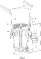
Figure 1 is a perspective cut-away view of a brewer system, according to an embodiment of the present invention. -
Figure 2 is a perspective cut-away view of the brewer system ofFigure 1 , a piston being shown at a bottom of a chamber. -
Figure 3 is a perspective view of a driving mechanism, according to one embodiment. -
Figure 4 is an enlarged view of a dispensing mechanism of the brewer system ofFigure 1 . -
Figures 5A to 5C are partial cut-away perspective views of a trigger device triggering a dispensing mechanism, according to one embodiment. -
Figure 6 is a perspective view of a wiping mechanism, according to one embodiment. -
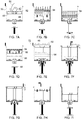
Figures 7A to 7I are cut-away views of the interior of a brewer system showing various stages of a method for making a beverage, according to another embodiment. -
Figures 8A to 8C are cut-away views of the interior of a brewer system showing a movement of a piston and a cleaning fluid, according to another embodiment. - In the following description, the same numerical references refer to similar elements. Furthermore, for sake of simplicity and clarity, namely so as to not unduly burden the figures with several reference numbers, not all figures contain references to all the components and features of the illustrated embodiments and references to some components and features may be found in only one figure, and components and features illustrated in other figures can be easily inferred therefrom. The embodiments, geometrical configurations, materials mentioned and/or dimensions shown in the figures are optional, and are provided for exemplification purposes only.
- In addition, although the embodiments illustrated in the accompanying drawings include various components and although the described embodiments of the system and method as shown consist of certain geometrical configurations as explained and illustrated herein, not all of these components and geometries are considered essential and thus should not be taken in their restrictive sense, i.e. should not be taken as to limit the scope of the system and method. It is to be understood that other suitable components and cooperations thereinbetween, as well as other suitable geometrical configurations may be used for the system and corresponding parts, as briefly explained herein, without departing from the scope of the invention.
- The present description relates to a brewer system (sometimes referred to as simply "system") and a method for making a beverage from a mixture of liquid and infusible solid particles. The system and method can be used to make a beverage and to dispense it, such as into a user's cup, for example. The term "making" refers to the bringing about or creation of the beverage from the mixture of liquid and solid particles.
- The liquid so mixed can be any suitable liquid used for making beverages. The most common example of such a liquid includes water, heated or not heated, which is used in most beverages fit for human consumption. In some instances, it may be desired to use liquids other than water, such as milk, cream, syrup, and juices. The expression "infusible solid particles" refers to any solid capable of being mixed with a liquid to create a solution. The solid particles can be of any size or shape provided that they are "infusible", which refers to their ability to at least partially dissolve and/or to impart a flavouring or quality to the liquid. Some examples of such infusible solid particles include coffee, tea, and chocolate. Consequently, the term "beverage" as used herein refers to the state of the mixture once the liquid has been suitably infused with the solid particles such that the mixture is ready to be consumed. Some examples of beverages that can be made according to the system and method include coffee, tea, hot chocolate, and juice. Different properties can also be imparted to such beverages by modifying some of the parameters of the system or method.
- Referring to
Figure 1 , and according to one embodiment of the invention, there is provided abrewer system 20 for making and dispensing a beverage from a mixture of liquid and infusible solid particles. The expression "brewer system" as used herein refers to a mechanism or assembly which allows for the making of a beverage through processes such as soaking, boiling, and mixing. Although not described in detail in the present disclosure, it is understood that some of the features of thesystem 20 can be supported by various support structures such as a support frame, housings, and other similar structures. - The
brewer system 20 has achamber 30 for receiving the liquid and the particles. Thechamber 30 is the component of thesystem 20 which receives the mixture of liquid and solid particles, and which houses the mixture while it is being made into the beverage. Thechamber 30 can therefore take any shape, or be of any appropriate dimension, provided that it can receive and hold a sufficient quantity of mixture for a desired application. Thechamber 30 can thus be cylindrical, rectangular, triangular, or any other suitable shape. Thechamber 30 can also be made of any suitable material. In some embodiments, the material of the chamber is preferably resistant the cyclical stresses associated with repeated infusion cycles, and can resist the pressure and temperature generated during these cycles, among other factors. As such, some examples of the materials that can be used for thechamber 30 include thermoplastics or other polymers, and metal alloys. - The
chamber 30 has aninner surface 32, and anoutlet 34. Theoutlet 34 may be embodied by any suitable aperture, release, duct, or other like structure from which the beverage or mixture can be dispensed. - The
brewer system 20 also includes apiston 40 in sealed contact with theinner surface 32, and which is displaceable within thechamber 30. Thepiston 40 provides a barrier between portions of thechamber 30 such that liquids, solids, and gasses from one portion can only pass through thepiston 40 to another portion of thechamber 30 under certain conditions. This barrier allows thepiston 40 to push/pull liquids, solids, and gasses as required. Thepiston 40 can be any disc, cylinder, head, or other like device or assembly which abuts against theinner surface 32 and can move within thechamber 30 while keeping this contact. Indeed, thepiston 40 is in "sealed contact" with theinner surface 32, which is understood to mean that thepiston 40 fits closely within theinner surface 32 such that liquids, solids, or gas cannot substantially bypass the interface between the piston's 40 edges and theinner surface 32. One possible technique by which this sealed contact can be achieved is through the use of gaskets or other suitable seals mounted about the edge of thepiston 40, these seals abutting against theinner surface 32. In order to facilitate the movement of thepiston 40 while still maintaining the sealed contact of thepiston 40 with theinner surface 32, theinner surface 32 may be made of a material, or have a material added to it, which reduces the friction caused by the sealed contact. - The
piston 40 is vertically displaceable within thechamber 30, that is, it can move both upward and downward in thechamber 30, against theinner surface 32. The use of the terms "up" and "down" to describe the motion of thepiston 40 may be used in a relative sense, meaning that thepiston 40 can be displaced vertically within the fixedchamber 30, or alternatively, thechamber 30 can be moved vertically with respect to a fixedpiston 40. Irrespective of such relative motion, thepiston 40 divides thechamber 30 into both anupper portion 42 corresponding to the portion of thechamber 30 above thepiston 40, and alower portion 44 corresponding to the portion of thechamber 30 below thepiston 40. One skilled in the art will readily understand that the relative dimensions of the upper andlower portions piston 40 is vertically displaced, since the upper andlower portions piston 40. - The
piston 40 also has afilter 46. Thefilter 46 allows for the passage of liquid and gas from above and below the filter, while preventing the passage of some solids. As such, thefilter 46 may be embodied by any suitable permeable device which can remove the solid particles from the mixture after sufficient infusion and which allows passage of the mixture therethrough, so as to form the beverage. Thefilter 46 can also allow the passage of gasses (i.e. air) between the upper andlower portions filter 46 can be sufficiently fine that liquid and gasses can only pass through under pressure. Some examples of suitable filters include polyester or stainless steel woven cloth, and etched metal sheet. Some examples of suitable filter materials include stainless steel, aluminum, polyester, nylon, or a combination thereof. To achieve these functions, thefilter 46 can be positioned at any suitable location on thepiston 40. One example of such a location is provided inFigure 1 , where thepiston 40 is shown as a circular head, thefilter 46 forming a circular area which is integral with thepiston 40. In one possible embodiment, thefilter 46 can be a filter assembly, which includes a filter frame onto which one or more very fine filtering components are mounted. - The
piston 40 is configured to allow the mixture to collect in theupper portion 42 of thechamber 30. Once the liquid and solid particles are added into thechamber 30, they may contact thefilter 46. Thefilter 46 can form a barrier which prevents them from passing into thelower portion 44, thus allowing the mixture to collect in theupper portion 42, and allowing the liquid to infuse with the quality or flavour of the solid particles. Advantageously, this can allow the mixture to infuse even before thepiston 40 has been vertically displaced, thus reducing infusing times. - The
brewer system 20 also has adriving mechanism 50 which is mounted to thepiston 40, and which displaces thepiston 40 within thechamber 30 according to an infusion cycle. Thedriving mechanism 50 drives thepiston 40 upward and downward within thechamber 30 throughout the stages of the infusion cycle, as described further below, thereby allowing the mixture to agitate and to be filtered, so as to form the beverage. - One example of a
driving mechanism 50 is provided inFigure 3 . In this embodiment, thedriving mechanism 50 includes apiston rod 52 which is mounted to thepiston 40. Thepiston rod 52 may be embodied by any mechanical component actuating thepiston 40, thereby allowing it to be displaced vertically. In the illustrated embodiment thepiston rod 52 is itself actuated by adrive motor 54, which provides the motive force required to move thepiston rod 52. Some examples ofdrive motors 54 include suitable AC and DC motors. The cooperation of thepiston rod 52 and thedrive motor 54 can take many different forms. In one possible example (not shown), thepiston rod 52 is mounted to a rotating cam, where the rotation of the cam allows thepiston rod 52 to move upwards and downwards according to the cycle of the cam's rotation. The cam itself can be driven by thedrive motor 54. In another possible embodiment, and as exemplified inFigure 3 , thepiston rod 52 is mounted to arotatable drive screw 56, which is driven by thedrive motor 54. As thedrive motor 54 rotates thedrive screw 56, thepiston rod 52, and thus thepiston 40 attached thereto, can be raised or lowered depending on the direction of rotation of thedrive screw 56. Of course, other or additional mechanical components or devices such as shafts, screws, gears and the like may be used to transfer movement between thepiston 40,piston rod 52 andmotor 54 and many other configurations of thedriving mechanism 50 are possible. - In some embodiments, the
driving mechanism 50 may also have atrigger device 58 mounted about thepiston rod 52 so as to be raised and lowered with the vertical displacement of thepiston rod 52. In the illustrated embodiment, the raising of thetrigger device 58 triggers the dispensing mechanism, thereby causing the release of the beverage from the chamber. Thetrigger device 58 can thus be any suitable mechanism which activates, causes, brings about, or generates the release of the beverage from the chamber. Some examples of atrigger device 58, as well as its operation, are described below. - Referring to
Figures 1 and2 , thedriving mechanism 50 displaces thepiston 40 within thechamber 30 according to an infusion cycle. The infusion cycle is the process by which the mixture is made into a beverage. Other functions of thesystem 20 can also coincide with the infusion cycle. For example, the release of the beverage from thesystem 20 can be configured to match with the movement of thepiston 40 according to the infusion cycle. In yet another example, the wiping of spent solid particles can be timed to begin when thepiston 40 reaches a certain point in the infusion cycle. As such, the infusion cycle can be various alternation, circuit, loop, periodicity, etc. which governs the movement of thepiston 40 within thechamber 30 so as to allow the mixture to be made into a beverage, among other possible outcomes. - Referring to
Figure 1 , the infusion cycle first involves displacing thepiston 40 downward within thechamber 30. Before the infusion cycle begins, thepiston 40 can be at an initial position where it receives a suitable initial quantity of liquid and solid particles, while still being able to be downwardly displaced. One example of such a position is mid-height in thechamber 30, or just above mid-height. The liquid and solid particles may be introduced in theupper portion 42 prior to the downward displacement of thepiston 40, for example while the piston is held in this initial position, or simultaneously while it is being downwardly displaced, at least partially. As thepiston 40 is displaced downward, air from the sealedlower portion 44 of the chamber is forced from below thepiston 40 through thefilter 46, and into the mixture of liquid and solid particles, which is in theupper portion 42. The mixture is thus agitated by the incoming air, thereby helping the liquid to better infuse with the flavour or quality of the solid particles. - Referring now to
Figure 2 , once at or near the bottom of thechamber 30, thepiston 40 is then displaced upward within thechamber 30. This upward displacement draws the agitated mixture from theupper portion 42 and through thefilter 46. This drawing action allows the infused liquid to be separated from the spent solid particles, and the infused liquid, now forming the beverage, collects belowpiston 40 in thelower portion 44, while the spent particles remain above thefilter 46. The infusion cycle may be repeated as much as is desired, and can also be varied. For example, the course of the vertical displacement of thepiston 40 can be limited or extended, or its displacement speed varied, so as to shorten or lengthen infusion times. In yet another example, the infusion cycle may include a pause period, for example between the downward and upward movement of thepiston 40, so as to allow the liquid to infuse with the flavour or quality of the solid particles before the drawing action. - Referring to
Figure 1 , and in some optional embodiments, it may be desirable to regulate the pressure within thelower portion 44. For example, after thepiston 40 is displaced upward near the end of the infusion cycle and the beverage is emptied from thelower portion 44 to a beverage container, the pressure within thelower portion 44 will be equal to atmospheric pressure. It may thus be desirable to raise or lower the pressure within thelower portion 44. One example involving such pressure regulation includes the depressurization of thelower portion 44 prior to emptying the beverage so as to dispense the beverage quicker. Such depressurization can be achieved with anair pump 22, or with a vent, vacuum or valve. In another example of pressure regulation, the pressure within thelower portion 44 can be increased with theair pump 22 so as to provide additional agitation to the mixture when thepiston 40 is displaced downward during the first part of the infusion cycle. Theair pump 22 can also be used to heat thechamber 30. - The
brewer system 20 also has adispensing mechanism 60, an example of which is provided inFigure 1 . Thedispensing mechanism 60 is mounted about theoutlet 34 of thechamber 30, which permits thedispensing mechanism 60 to allow, or prevent, the release of the beverage out of thelower portion 44 of thechamber 30, and thus out of thesystem 20. In most embodiments, thedispensing mechanism 60 will release the mixture only once it has been made into a beverage suitable for consumption. The operation of thedispensing mechanism 60 may be governed by the infusion cycle, such that the vertical displacement of thepiston 40 determines when and how the beverage will be dispensed from thesystem 20. In other variants the dispensing mechanism may be triggered by other devices external to the displacement of thepiston 40. - One possible example of a
dispensing mechanism 60 is shown inFigure 4 . In this embodiment, thedispensing mechanism 60 includes aspout 62 which is in fluid connection with theoutlet 34 of thechamber 30. The expression "fluid connection" is understood to mean that thespout 62 receives fluids, such as the beverage, from theoutlet 34, and is thus suitably connected to theoutlet 34. Thespout 62 can take any suitable shape, and can be of any suitable size. In the embodiment shown inFigure 4 , thespout 62 is substantially "L"-shaped, such that the beverage entering thespout 62 from theoutlet 34 will be turned substantially 90 degrees before exiting thespout 62. Of course, thespout 62 is not limited to this particular configuration. Thespout 62 includes anintake 64 which receives the beverage from theoutlet 34. Theintake 64 conveys the beverage to anouttake 66 of thespout 62, from which the beverage can be directed out of the system. - The
dispensing mechanism 60 can also include aplug 68, which acts as a stop to the flow of the beverage from thechamber 30 to thespout 62. Theplug 68 can be alternatingly affixed to, and removed from, theintake 64 of thespout 62. Theplug 68 can also be mounted directly to theoutlet 34 of thechamber 30. Theplug 68 may operate through two positions, the open position and the closed position. In the open position, theplug 68 is raised from its contact with theintake 64 and/oroutlet 34, which allows the beverage into thespout 62, and thus allows the beverage to leave thesystem 20. In the closed position, theplug 68 is in sealed contact with theintake 64 and/oroutlet 34, thus preventing the beverage from entering thespout 62 and allowing the beverage to collect in thelower portion 44 of thechamber 30. - The transition of the
plug 68 from the closed to open positions is preferably achieved by the vertical displacement of thetrigger device 58. An example of such a displacement is provided inFigures 5A to 5C . Thetrigger device 58 is shown as a collar 58a, which can be mounted about thepiston rod 52 so as to be vertically displaced along with it. As thepiston rod 52 and thepiston 40 are displaced vertically upward within thechamber 30 in the direction of the arrow indicated inFigure 5B , thus drawing the mixture through thefilter 46 and separating it from the spent solid particles which remain above thefilter 46, the collar 58a is vertically displaced upward as well. Once thepiston 40 reaches a certain trigger height, and as shown inFigure 5C , the collar 58a abuts against thespout 62 from underneath. In the example provided inFigure 5C , the collar 58a abuts against arim 62a of thespout 62, thus raising thespout 62. As thespout 62 is raised, theplug 68 is raised along with it from the floor of thechamber 30, thus placing theplug 68 in the open position. The trigger height may be any suitable height of thepiston 40 within thechamber 30 which triggers the transition of theplug 68 from the closed to the open position. One example of the trigger height can include the height of thepiston 40 once it has reached the top of the chamber 30 (i.e. the end of the piston's 40 stroke). Once the collar 58a abuts against thespout 62 from underneath, theplug 68 is pushed upward into thelower portion 44 of thechamber 30, which corresponds to the open position. This creates an opening in theoutlet 34 through which the beverage can exit thechamber 30 and flow into thespout 60. Once thepiston 40 begins to vertically descend, the collar 58a no longer abuts against thespout 62, and theplug 68 can return to the closed position, thus preventing the beverage from leaving thechamber 30. - In some possible embodiments, the brewer system includes a wiping mechanism for wiping the spent solid particles from a top surface of the piston.
Figure 6 provides one example of such awiping mechanism 70. - Once the
piston 40 has been vertically displaced to the top of thechamber 30, the spent solid particles which infused the liquid with their flavour or quality are no longer useful and thus can be disposed of. These spent solid particles may collect on atop surface 48 of thepiston 40 or adjacent thereto. Thewiping mechanism 70 disposes of these spent solid particles by wiping them from thetop surface 48 and into a suitable collector for disposal (not shown). Thewiping mechanism 70 may operate independently from, or along with, the infusion cycle, that is, with the movement of the piston. Other control schemes for thewiping mechanism 70 may however be devised without departing from the scope of the invention. In one possible configuration, thewiping mechanism 70 is activated immediately upon thepiston 40 reaching the top of thechamber 30. Alternatively, thewiping mechanism 70 can wipe thetop surface 48 at any moment during the infusion cycle after the beverage has been extracted from the top portion. - In some embodiments, the
wiping mechanism 70 includes awiper 72 which wipes the spent solid particles from thetop surface 48. Thewiper 72 can be moved along any suitable guiding mechanism, such as guide rails, so as to be able to pass over thetop surface 48 and to return to its initial position, as many times as is necessary. Thewiper 72 can also wipe the areas of thechamber 30 adjacent to thetop surface 48. Thewiper 72 is in contact with thetop surface 48, and the force of such contact can be fixed initially and be adjusted after a certain number of uses. - The
wiper 72 can be driven by awiper arm 74, which is connected thereto. Thewiper arm 74 displaces thewiper 72 along a first direction and a second direction. In the first direction, thewiper 72 wipes the spent solid particles from thetop surface 48, and in the second direction, thewiper 72 returns to its initial position. Upon returning, thewiper 72 may also wipe any remaining spent solid particles that were not wiped during the passage of thewiper 72 in the first direction. When being displaced in either the first or second directions, thewiper 72 can dispense of the spent solid particles into a waste receptacle. Alternatively, thepiston 40 can be lowered below the top of thechamber 30 so that the return of thewiper 72 does not soil thetop surface 48 of thepiston 40. Thewiper arm 74 can be driven by awiper motor 76, which can be any suitable electric motor. Thewiper motor 76 moves thewiper arm 74 between the first and second directions. It is understood thatwiper 72 can be displaced from any initial position so as to travel in either the first or second direction. - It is to be noted that various components of the system as described above are preferably made of substantially hardened materials, such as metals, alloys, polymers, composite materials, and/or the like, depending on the particular applications for which the system is intended for, and the different parameters in cause (temperature of liquids, corrosion, filter clogging, dimensions, etc.).
- According to another embodiment of the present invention, there is provided a method for making a beverage from a mixture of liquid and infusible solid particles. The steps of method will now be described with reference to the accompanying figures. Some of the steps of the method may correspond to the brewer system's infusion cycle. In most embodiments of the method, the chamber is a sealed system, and the piston is a means by which the pressure within the upper and lower portions of the chamber can be equalized. Indeed, the making of the beverage results from the pressure fluctuations created in the chamber by the movement of the piston.
- Figure 9A provides an example of step a) of the method, where the liquid 90 and
solid particles 92 are introduced into theupper portion 42 of thechamber 30, thereby forming the mixture. The liquid 90 and thesolid particles 92 can be added in any particular order. In some embodiments, the liquid 90 andsolid particles 92 may be mixed to form themixture 94 before being added to thechamber 30. The liquid 90 andsolid particles 92 collect in theupper portion 42 because the filter of thepiston 40 is not permeable to the solid particles, and may only be permeable to the liquid 90 under pressure. Thus, step a) allows for the liquid 90 andsolid particles 92 to form a mixture. The initial position of thepiston 40 can be at any suitable height, and is preferably high enough within the chamber so that sufficient agitation can be caused by the downward displacement of thepiston 40, and high enough so that the introduction of the liquid and agitation of the mixture does not cause substantial splashing/spills from the top of thechamber 30. - Figures 9B and 9C provide examples of step b) of the method, where the
piston 40 is displaced downward within thechamber 30. This downward displacement of thepiston 40 reduces the volume of thelower portion 44, which in a sealed system, results in the gaseous pressure of thelower portion 44 increasing such that it is greater than the pressure in theupper portion 42. This pressurized gas (i.e. air) seeks release, and finds it by leaving thelower portion 44 through the filter of thepiston 40 and into theupper portion 42. As the air is forced into theupper portion 42, it passes through themixture 94, thereby causing turbulence, and thus agitating themixture 94. This agitation can continue until thepiston 40 has reached a bottom of thechamber 30, as exemplified in Figure 9C, at which point relatively little air can be forced from thelower portion 44 to theupper portion 42. Thepiston 40 can pause at this point for an appropriate infusing period, for example a few seconds, so as to allow the agitated mixture to further infuse. - In some possible embodiments, steps a) and b) of the method are performed concurrently, that is, at the same time. As the
piston 40 moves downward, the volume of theupper portion 42 increases, which advantageously allows more liquid 90 and/orsolid particles 92 to be added to theupper portion 42. Thus, thechamber 30 is able to holdmore mixture 94, and ultimately, produce more beverage, during a single infusion cycle. - Figure 9D provides an example of step c) of the method, where the
piston 40 is displaced upwardly within thechamber 30 so as to draw thebeverage 96 from theupper portion 42 into thelower portion 44. In most embodiments, the act of drawing themixture 94 through the filter of thepiston 40 results in the making of thebeverage 96 because themixture 94, once it is separated from the spentsolid particles 92, consists of the infused liquid, and is thus ready for consumption. This upward displacement of thepiston 40 increases the volume of thelower portion 44, which in a sealed system, results in the pressure of thelower portion 44 decreasing to a level below the pressure of theupper portion 42. The pressure differential between the upper andlower portions mixture 94 in theupper portion 42, driving it through the filter and into thelower portion 44. The filter of thepiston 40 permits only the infused liquid 90 (i.e. the beverage 96) to pass through it, while the spentsolid particles 92 remain above the filter. - In some embodiments, and as exemplified in Figures 9E to 91, the method includes the additional step of removing the spent solid particles from above the filter when the
piston 40, or thetop surface 48 of thepiston 40, reaches a top of thechamber 30. Alternatively, thetop surface 48 can be wiped by a wiping mechanism which descends below the level of the top of thechamber 30. The wiping can be done by a wiping mechanism, such as the one described above, which can include awiper 72 which wipes thetop surface 48 of thepiston 40. - In some embodiments, and as exemplified in Figures 9E and 9F, the method includes the additional step of dispensing the
beverage 96 from thelower portion 44 and into a beverage container, for example a mug or cup (not shown). This can be achieved with a dispensing mechanism, such as the one described above, which can be triggered to release thebeverage 96 once thepiston 40 reaches a trigger height within thechamber 30. - In another possible embodiment, and as exemplified in Figures 10A to 10C, the method includes the additional step of cleaning the
piston 40, filter, and thechamber 30. It is known that the build-up of residue and/or spent solid particles can affect the performance of the system. In order to address this problem, thebrewing system 20 can be cleaned, and the frequency of such cleaning can vary. Figure 10A provides an example of sub-step A) of the additional step, where a cleaning fluid 98 is introduced into theupper portion 42 of thechamber 30. The cleaning fluid 98 can be introduced by gravity, or under pressure, and cleans both the inner surface 38 of thechamber 30 and thetop surface 48 of thepiston 40. Furthermore, the sealed contact of thepiston 40 with theinner surface 32 allows thepiston 40 to sweep spent solid particles off theinner surface 32 as thepiston 40 is vertically displaced. Before the cleaning fluid 98 is added, thepiston 40 can be located at any suitable height within the chamber provided that the cleaning fluid 98 can be drawn through the filter of thepiston 40. - Figure 10B provides an example of sub-step B), where the
piston 40 is displaced upward within thechamber 30. This upward displacement of thepiston 40 draws the cleaning fluid 98 from theupper portion 42, through the filter, and into thelower portion 44. In so doing, the filter is cleaned by the cleaning fluid 98 as it passes through the filter. Furthermore, the edges of thepiston 40 may be lubricated by the presence of cleaning fluid 98 on theinner surface 32 such that the displacement of thepiston 40 cleans the walls of theinner surface 32, and thus the interior of thechamber 30. Thepiston 40 does not need to be fully upwardly displaced (i.e. does not have to complete its full stroke), and can instead be upwardly displaced only enough so that a certain volume of cleaning fluid 98 can pass through the filter. Figure 10C provides an example of sub-step C), where thepiston 40 is displaced downwardly within thechamber 30 to below a level of the cleaning fluid 98. By descending below the level of the cleaning fluid 98, the cleaning fluid 98 is forced upward from thelower portion 44 and through the filter, which provides a pressurized cleaning to the bottom surface of thepiston 40 and/or filter. - The system and method for making a beverage according to described embodiments may provide advantages over other systems and methods known in the art. Advantageously, in some embodiments the movement of the piston downward so as to agitate the mixture increases the volume of the upper portion, thereby allowing additional solid particles and liquid to be added to the chamber and further increasing brewing capacity. This can thus allow for the removal of superimposed chambers known the in the art without compromising beverage output capacity. Further advantageously, the ability to agitate the mixture by displacing the piston downward may dampen the "volcano effect", which can occur when the agitation of the mixture causes the mixture to escape from the chamber. In agitating the mixture by driving it away from the top of the chamber, a more powerful agitation for a given chamber volume can be applied.
- Furthermore, in some embodiments the drive motor can control the vertical displacement of the piston rod independently of the wiper motor controlling the movement of the wiper arm. This use of independent drive and wiper motors allows for the brewing and wiping cycles to be controlled separately from each other. Therefore, as the collar of the piston rod is pushing the plug so as to release the beverage from the chamber, the wiper motor can be moving the wiper arm and the wiper across the top surface, and both such movements can be coordinated independently of each other. Alternatively, such coordination of the beverage release and wiper can be performed alone by either the driver motor or the wiper motor. Another advantage of an independent drive motor is that the agitation and drawing actions can be accelerated, decelerated, and modulated to fit the exact infusing cycle required, while not affecting any of the other functions of the brewer system. For example, such independent control allows clockwise as well as counterclockwise rotation of the drive motor. Similarly, independent operation of the wiper motor can allow for the optimization of system parameters such as wiper positioning, speed, acceleration, deceleration, and other similar parameters.
- Furthermore, the cleaning of the brewer system allows for hands-off maintenance and system upkeep. Such self-cleaning may be desirable when the system is used directly by consumers.
Claims (16)
- A brewer system (20) for making and dispensing a beverage from a mixture of liquid and infusible solid particles, the system comprising:a chamber (30) for receiving the liquid and the particles, the chamber being provided with an inner surface (32) and an outlet (34) for dispensing the beverage;a piston (40) in sealed contact with the inner surface (32) and vertically displaceable within the chamber (30), the piston dividing the chamber into an upper portion (42) above the piston and a sealed lower portion (44) below the piston, the piston comprising a filter (46) and configured so that the mixture collects in the upper portion;a driving mechanism (50) mountable to the piston (40) and configured for displacing the piston within the chamber (30) according to an infusion cycle, the infusion cycle comprising displacing the piston downward within the chamber, thereby forcing air from the sealed lower portion (44) through the filter (46) and into the upper portion (42) so as to agitate the mixture, and subsequently displacing the piston upward within the chamber, thereby drawing the beverage from the upper portion through the filter and into the sealed lower portion while spent solid particles remain above the filter; anda dispensing mechanism (60) mounted about the outlet (34) of the chamber (30), the dispensing mechanism dispensing the beverage out of said brewer system.
- A brewer system according to claim 1, wherein the driving mechanism (50) comprises:a piston rod (52) mounted to the piston (40);a drive motor (54) operatively connected to the piston rod (52), the drive motor vertically displacing the piston rod within the chamber (30); anda trigger device (58) mounted about the piston rod, the trigger device being vertically displaced concurrently with the piston rod so as to trigger the dispensing mechanism.
- A brewer system according to claim 2, wherein the piston rod (52) is mounted about a rotatable drive screw (56), the drive screw being rotated by the drive motor (54) so as to vertically displace the piston rod.
- A brewer system according to claim 2 or 3, wherein the dispensing mechanism (60) comprises:a spout (62) in fluid connection with the outlet (34) of the chamber (30), the spout comprising an intake (64) for receiving the beverage from the outlet and an outtake (66) for directing the beverage out of the brewer system; anda plug (68) removably mounted to the intake (64) of the spout (62), the plug preventing the beverage from entering the spout when in a closed position, and the plug allowing the beverage to enter the spout when in an open position, the plug being transitioned between the open and closed positions by the displacement of the trigger device (58).
- A brewer system according to claim 4, wherein the trigger device (58) transitions the plug (68) to the open position upon the trigger device being displaced vertically upward.
- A brewer system according to anyone of claims 2 to 5, further comprising a wiping mechanism (70) for wiping the spent solid particles from a top surface of the piston.
- A brewer system according to claim 6, wherein the wiping mechanism (70) comprises:a wiper (72) for wiping the spent solid particles from the top surface;a wiper arm (74) connected to the wiper, the wiper arm displacing the wiper in a first direction so as to wipe the spent solid particles, and in an opposed second direction so as to return the wiper; anda wiper motor (76) functionally connected to the wiper arm, the wiper motor moving the wiper arm between the first and second directions.
- A brewer system according to claim 7, wherein the drive motor (54) controls the vertical displacement of the piston rod (52) independently of the wiper motor (76) controlling the movement of the wiper arm (74).
- A method for making a beverage from a mixture of liquid and infusible solid particles using a chamber (30) having a piston (40) in sealed contact therewith and vertically displaceable therein, the piston comprising a filter (46) and dividing the chamber into an upper portion (42) above the piston and a sealed lower portion (44) below the piston, the method comprising the steps of:a) introducing the liquid and solid particles into the upper portion (42) of the chamber (30);b) displacing the piston (40) downward within the chamber (30) to force air from the sealed lower portion through the filter (46) and into the upper portion (42) so as to agitate the mixture; andc) displacing the piston upward within the chamber to draw the beverage from the upper portion through the filter and into the sealed lower portion while spent solid particles remain above the filter.
- A method according to claim 9, comprising an additional step of removing the spent solid particles from above the filter (46) when the piston (40) reaches a top of the chamber (30).
- A method according to claim 10, wherein removing the spent solid particles comprises wiping the spent solid particles off the filter (46) with a wiping mechanism (70).
- A method according to any one of claims 9 to 11, comprising an additional step of dispensing the beverage from the sealed lower portion (44) into a beverage container.
- A method according to claim 12, wherein said dispensing comprises triggering a dispensing mechanism (60) disposed within the sealed lower portion (44) of the chamber (30) when the piston (40) reaches a trigger height within the chamber, thereby dispensing the beverage.
- A method according to any one of claims 9 to 13, wherein step a) and step b) are performed concurrently.
- A method according to any one of claims 9 to 14, comprising an additional step between steps b) and c) of pausing the piston (40) at a bottom of the chamber (30) for an infusing period so as to allow the mixture to infuse.
- A method according to any one of claims 9 to 15, comprising an additional step of cleaning the piston (40), the filter (46), and the chamber (30), said additional step comprising the sub-steps of:A) introducing a cleaning fluid into the upper portion of the chamber;B) displacing the piston (40) upward within the chamber so as to draw the cleaning fluid from the upper portion through the filter and into the lower portion; andC) displacing the piston downward within the chamber below a level of the cleaning fluid, thereby forcing at least part of the cleaning fluid from the lower portion and through the filter.
Applications Claiming Priority (2)
| Application Number | Priority Date | Filing Date | Title |
|---|---|---|---|
| US201261737324P | 2012-12-14 | 2012-12-14 | |
| PCT/CA2013/050962 WO2014089705A1 (en) | 2012-12-14 | 2013-12-13 | System and method for making a beverage |
Publications (3)
| Publication Number | Publication Date |
|---|---|
| EP2934245A1 EP2934245A1 (en) | 2015-10-28 |
| EP2934245A4 EP2934245A4 (en) | 2016-09-28 |
| EP2934245B1 true EP2934245B1 (en) | 2019-07-10 |
Family
ID=50931192
Family Applications (1)
| Application Number | Title | Priority Date | Filing Date |
|---|---|---|---|
| EP13862886.2A Active EP2934245B1 (en) | 2012-12-14 | 2013-12-13 | System and method for making a beverage |
Country Status (4)
| Country | Link |
|---|---|
| US (2) | US20140170280A1 (en) |
| EP (1) | EP2934245B1 (en) |
| CA (1) | CA2911411C (en) |
| WO (1) | WO2014089705A1 (en) |
Families Citing this family (21)
| Publication number | Priority date | Publication date | Assignee | Title |
|---|---|---|---|---|
| WO2015077237A2 (en) | 2013-11-20 | 2015-05-28 | Starbucks Corporation D/B/A Starbucks Coffee Company | Cooking system power management |
| US11292706B2 (en) * | 2014-12-30 | 2022-04-05 | Edward Showalter | Apparatus, systems and methods for preparing and dispensing foods |
| US10647563B2 (en) * | 2014-12-30 | 2020-05-12 | Edward Showalter | Apparatus, systems and methods for dispensing drinks |
| US9962030B2 (en) * | 2015-01-12 | 2018-05-08 | Voga Coffee, Inc. | Coffee brewing system with features for rapid and/or multiple extraction processes |
| WO2017100326A1 (en) | 2015-12-07 | 2017-06-15 | Bunn-O-Matic Corporation | Brewer system, method and apparatus |
| US20170318999A1 (en) * | 2016-05-05 | 2017-11-09 | Teforia Company | Apparatus for Brewing a Beverage |
| KR102231060B1 (en) * | 2016-05-10 | 2021-03-24 | 후지 덴키 가부시키가이샤 | Beverage extraction device |
| JP2017202044A (en) * | 2016-05-10 | 2017-11-16 | 富士電機株式会社 | Beverage extraction apparatus |
| JP6866735B2 (en) * | 2016-05-10 | 2021-04-28 | 富士電機株式会社 | Beverage extractor |
| JP6852280B2 (en) * | 2016-05-10 | 2021-03-31 | 富士電機株式会社 | Beverage extraction method |
| KR102212235B1 (en) * | 2016-09-01 | 2021-02-04 | 후지 덴키 가부시키가이샤 | Beverage brewing device |
| US11659953B2 (en) | 2016-12-13 | 2023-05-30 | Bunn-O-Matic Corporation | Bean to cup positive pressure brewer |
| JP6816599B2 (en) * | 2016-12-22 | 2021-01-20 | 富士電機株式会社 | Beverage extractor |
| CN107581908B (en) * | 2017-10-09 | 2019-09-10 | 吴建威 | Easily-unloaded coffee high-pressure brewing device with foam generation function |
| US11523703B2 (en) | 2018-01-23 | 2022-12-13 | Bunn-O-Matic Corporation | Brewer system, method and apparatus |
| WO2019195767A1 (en) * | 2018-04-05 | 2019-10-10 | Voga Coffee, Inc. | Temperature control for extracted beverages, including coffee, via controlled vacuum, and associated systems and methods |
| US10729274B2 (en) | 2018-06-11 | 2020-08-04 | Todd Ewing | Cold brew compositions and methods |
| CN114668294A (en) * | 2022-03-08 | 2022-06-28 | 佛山市贝童电器科技有限公司 | Milk warming device |
| WO2024044580A1 (en) * | 2022-08-22 | 2024-02-29 | J Dean Llc | Brew chamber for french press coffee machine |
| US12520963B2 (en) | 2022-10-18 | 2026-01-13 | Kaz Europe Sàrl | Handheld filter press |
| USD1104619S1 (en) | 2024-06-05 | 2025-12-09 | Kaz Europe Sàrl | Pump coffee maker |
Family Cites Families (27)
| Publication number | Priority date | Publication date | Assignee | Title |
|---|---|---|---|---|
| US2654505A (en) * | 1947-09-05 | 1953-10-06 | Elmer O Gerth | Automatic vending machine |
| US3369478A (en) * | 1966-04-22 | 1968-02-20 | Vendo Co | Single cup, dry waste coffee brewing and dispensing mechanism |
| US3565641A (en) | 1968-04-08 | 1971-02-23 | Alan M King | Coffee brewing machine |
| US3927608A (en) * | 1974-06-14 | 1975-12-23 | John S Doyel | Beverage making device |
| JPS61119141A (en) | 1984-11-15 | 1986-06-06 | Toshiba Electric Appliance Co Ltd | Method for detecting and extracting drink |
| IT1210382B (en) | 1987-06-23 | 1989-09-14 | Zanussi Grandi Impianti Spa | AUTOMATIC MACHINES FOR THE PREPARATION OF COFFEE OR SIMILAR. |
| US4903586A (en) | 1987-08-27 | 1990-02-27 | King Alan M | Coffee brewer |
| NL8901968A (en) | 1989-07-28 | 1991-02-18 | Jong J M Duke Automaten Bv De | DEVICE FOR PREPARING BEVERAGES BY EXTRACTION SUCH AS COFFEE OR TEA. |
| CH681198A5 (en) | 1990-07-23 | 1993-02-15 | Prodiana Ag | |
| EP0564399A2 (en) | 1992-03-19 | 1993-10-06 | COSMEC S.r.l. | Hot beverage making device |
| EP0563499A1 (en) | 1992-03-31 | 1993-10-06 | Liebi Lnc Ag | Wood gasification boiler |
| US5351604A (en) * | 1992-09-01 | 1994-10-04 | Zuma Coffee Technologies, Inc. | Coffee brewer method and apparatus |
| US5406882A (en) * | 1994-03-30 | 1995-04-18 | Shaanan Holdings Inc. | Brewer |
| CH689754A5 (en) * | 1995-07-31 | 1999-10-15 | Lough J Ltd | Machine for the realization of the coffee type beverages expressed with automatic introduction of the coffee powder and expulsion of the funds. |
| US5638739A (en) | 1996-07-08 | 1997-06-17 | Shaanan Holdings Inc. | Brewer |
| US5913963A (en) | 1998-06-01 | 1999-06-22 | King; Alan M. | Single cup brewer having special brew chamber |
| NL1014817C2 (en) | 2000-03-31 | 2001-10-02 | Jong Duke De | Coffee maker. |
| US7213507B2 (en) | 2004-03-12 | 2007-05-08 | Meyer Intellectual Properties Limited | Infusion beverage brewing system |
| TWI245617B (en) | 2004-09-29 | 2005-12-21 | Delos Vending Machine Co Ltd | An improvement structure of brewing chamber of coffee machine |
| WO2007027206A2 (en) | 2005-04-11 | 2007-03-08 | Coffee Equipment Company | Machine for brewing a beverage such as coffee and related method |
| EP1940268B1 (en) | 2005-04-11 | 2011-11-09 | Starbucks Corporation | Machine for brewing a beverage such as coffee and related method |
| US7849784B2 (en) * | 2005-05-18 | 2010-12-14 | Adler Alan J | Coffee or tea filtering press |
| CN200957018Y (en) | 2006-10-12 | 2007-10-10 | 广东亿龙电器股份有限公司 | Coffee powder pressing device of coffee maker |
| EP1922963A1 (en) * | 2006-11-16 | 2008-05-21 | Petervin S.A. | Apparatus and method for extracting a hot beverage |
| CN201260608Y (en) * | 2008-08-29 | 2009-06-24 | 胡振飞 | Full automatic or semiautomatic coffee machine pouring device |
| US8663724B1 (en) * | 2010-03-03 | 2014-03-04 | Food Equipment Technologies Company, Inc. | Automated beverage brewing method |
| CN104066362B (en) * | 2012-01-24 | 2018-01-09 | 班奥麦迪克公司 | Brewing machine |
-
2013
- 2013-03-14 US US13/828,431 patent/US20140170280A1/en not_active Abandoned
- 2013-12-13 WO PCT/CA2013/050962 patent/WO2014089705A1/en not_active Ceased
- 2013-12-13 EP EP13862886.2A patent/EP2934245B1/en active Active
- 2013-12-13 CA CA2911411A patent/CA2911411C/en active Active
-
2014
- 2014-12-23 US US14/580,617 patent/US9907427B2/en active Active
Non-Patent Citations (1)
| Title |
|---|
| None * |
Also Published As
| Publication number | Publication date |
|---|---|
| EP2934245A1 (en) | 2015-10-28 |
| US9907427B2 (en) | 2018-03-06 |
| CA2911411C (en) | 2018-09-25 |
| CA2911411A1 (en) | 2014-06-19 |
| US20150107459A1 (en) | 2015-04-23 |
| EP2934245A4 (en) | 2016-09-28 |
| US20140170280A1 (en) | 2014-06-19 |
| WO2014089705A1 (en) | 2014-06-19 |
Similar Documents
| Publication | Publication Date | Title |
|---|---|---|
| US9907427B2 (en) | System and method for making a beverage | |
| JP2808124B2 (en) | Coffee mixing filter | |
| CN105592757B (en) | Device for preparing a beverage | |
| EP2262402B1 (en) | Brewer system with active brewing mechanism and buffer reservoir piston compression of brewing substance | |
| CA2105220C (en) | Coffee brewer method and apparatus | |
| US8997633B2 (en) | Air agitation controllable beverage making apparatus, system and method | |
| US8039033B2 (en) | Method and device for preparing coffee | |
| CN101056561B (en) | Beverage machine with height adjustment means for controlling the distance between the beverage container and the outlet | |
| US5312637A (en) | One-cup brewer | |
| RU2752302C2 (en) | Liquid dispensing device with drop limiter | |
| EP0296478A1 (en) | Automatic machine for the preparation of coffee or the like | |
| JPH0439848B2 (en) | ||
| CN116507250B (en) | Coffee brewing equipment | |
| CN1427685A (en) | Device for extracting substance | |
| JP2021506397A (en) | Beverage preparation machine with convenient dripping prevention function | |
| EP3941319B1 (en) | Beverage extracting device | |
| GB2610878A (en) | An outlet nozzle arrangement for a drink dispensing apparatus | |
| JP3845740B2 (en) | Beverage production equipment | |
| JP5922847B2 (en) | Extractor for hot drink serving machine | |
| CN115671793A (en) | Fruit spice extraction and separation device | |
| WO2006003128A9 (en) | Brewed-beverage vending machine provided with means for cleaning the brewing filter | |
| CN115104919A (en) | Multifunctional office table | |
| CN117695907A (en) | Bubble type apocynum tea compound beverage preparation device and preparation method |
Legal Events
| Date | Code | Title | Description |
|---|---|---|---|
| PUAI | Public reference made under article 153(3) epc to a published international application that has entered the european phase |
Free format text: ORIGINAL CODE: 0009012 |
|
| 17P | Request for examination filed |
Effective date: 20150713 |
|
| AK | Designated contracting states |
Kind code of ref document: A1 Designated state(s): AL AT BE BG CH CY CZ DE DK EE ES FI FR GB GR HR HU IE IS IT LI LT LU LV MC MK MT NL NO PL PT RO RS SE SI SK SM TR |
|
| AX | Request for extension of the european patent |
Extension state: BA ME |
|
| DAX | Request for extension of the european patent (deleted) | ||
| A4 | Supplementary search report drawn up and despatched |
Effective date: 20160826 |
|
| RIC1 | Information provided on ipc code assigned before grant |
Ipc: A47J 31/46 20060101ALI20160822BHEP Ipc: A47J 31/18 20060101ALI20160822BHEP Ipc: A47J 31/60 20060101ALI20160822BHEP Ipc: A47J 31/20 20060101ALI20160822BHEP Ipc: A47J 31/10 20060101AFI20160822BHEP |
|
| GRAP | Despatch of communication of intention to grant a patent |
Free format text: ORIGINAL CODE: EPIDOSNIGR1 |
|
| STAA | Information on the status of an ep patent application or granted ep patent |
Free format text: STATUS: GRANT OF PATENT IS INTENDED |
|
| RIC1 | Information provided on ipc code assigned before grant |
Ipc: A47J 31/20 20060101ALI20190114BHEP Ipc: A47J 31/18 20060101ALI20190114BHEP Ipc: A47J 31/10 20060101AFI20190114BHEP Ipc: A47J 31/60 20060101ALI20190114BHEP Ipc: A47J 31/46 20060101ALI20190114BHEP |
|
| INTG | Intention to grant announced |
Effective date: 20190207 |
|
| GRAS | Grant fee paid |
Free format text: ORIGINAL CODE: EPIDOSNIGR3 |
|
| GRAA | (expected) grant |
Free format text: ORIGINAL CODE: 0009210 |
|
| STAA | Information on the status of an ep patent application or granted ep patent |
Free format text: STATUS: THE PATENT HAS BEEN GRANTED |
|
| AK | Designated contracting states |
Kind code of ref document: B1 Designated state(s): AL AT BE BG CH CY CZ DE DK EE ES FI FR GB GR HR HU IE IS IT LI LT LU LV MC MK MT NL NO PL PT RO RS SE SI SK SM TR |
|
| REG | Reference to a national code |
Ref country code: GB Ref legal event code: FG4D |
|
| REG | Reference to a national code |
Ref country code: CH Ref legal event code: EP Ref country code: AT Ref legal event code: REF Ref document number: 1152655 Country of ref document: AT Kind code of ref document: T Effective date: 20190715 |
|
| REG | Reference to a national code |
Ref country code: DE Ref legal event code: R096 Ref document number: 602013057764 Country of ref document: DE |
|
| REG | Reference to a national code |
Ref country code: IE Ref legal event code: FG4D |
|
| REG | Reference to a national code |
Ref country code: NL Ref legal event code: MP Effective date: 20190710 |
|
| REG | Reference to a national code |
Ref country code: LT Ref legal event code: MG4D |
|
| REG | Reference to a national code |
Ref country code: AT Ref legal event code: MK05 Ref document number: 1152655 Country of ref document: AT Kind code of ref document: T Effective date: 20190710 |
|
| PG25 | Lapsed in a contracting state [announced via postgrant information from national office to epo] |
Ref country code: PT Free format text: LAPSE BECAUSE OF FAILURE TO SUBMIT A TRANSLATION OF THE DESCRIPTION OR TO PAY THE FEE WITHIN THE PRESCRIBED TIME-LIMIT Effective date: 20191111 Ref country code: BG Free format text: LAPSE BECAUSE OF FAILURE TO SUBMIT A TRANSLATION OF THE DESCRIPTION OR TO PAY THE FEE WITHIN THE PRESCRIBED TIME-LIMIT Effective date: 20191010 Ref country code: HR Free format text: LAPSE BECAUSE OF FAILURE TO SUBMIT A TRANSLATION OF THE DESCRIPTION OR TO PAY THE FEE WITHIN THE PRESCRIBED TIME-LIMIT Effective date: 20190710 Ref country code: NL Free format text: LAPSE BECAUSE OF FAILURE TO SUBMIT A TRANSLATION OF THE DESCRIPTION OR TO PAY THE FEE WITHIN THE PRESCRIBED TIME-LIMIT Effective date: 20190710 Ref country code: LT Free format text: LAPSE BECAUSE OF FAILURE TO SUBMIT A TRANSLATION OF THE DESCRIPTION OR TO PAY THE FEE WITHIN THE PRESCRIBED TIME-LIMIT Effective date: 20190710 Ref country code: AT Free format text: LAPSE BECAUSE OF FAILURE TO SUBMIT A TRANSLATION OF THE DESCRIPTION OR TO PAY THE FEE WITHIN THE PRESCRIBED TIME-LIMIT Effective date: 20190710 Ref country code: SE Free format text: LAPSE BECAUSE OF FAILURE TO SUBMIT A TRANSLATION OF THE DESCRIPTION OR TO PAY THE FEE WITHIN THE PRESCRIBED TIME-LIMIT Effective date: 20190710 Ref country code: NO Free format text: LAPSE BECAUSE OF FAILURE TO SUBMIT A TRANSLATION OF THE DESCRIPTION OR TO PAY THE FEE WITHIN THE PRESCRIBED TIME-LIMIT Effective date: 20191010 Ref country code: FI Free format text: LAPSE BECAUSE OF FAILURE TO SUBMIT A TRANSLATION OF THE DESCRIPTION OR TO PAY THE FEE WITHIN THE PRESCRIBED TIME-LIMIT Effective date: 20190710 |
|
| PG25 | Lapsed in a contracting state [announced via postgrant information from national office to epo] |
Ref country code: ES Free format text: LAPSE BECAUSE OF FAILURE TO SUBMIT A TRANSLATION OF THE DESCRIPTION OR TO PAY THE FEE WITHIN THE PRESCRIBED TIME-LIMIT Effective date: 20190710 Ref country code: GR Free format text: LAPSE BECAUSE OF FAILURE TO SUBMIT A TRANSLATION OF THE DESCRIPTION OR TO PAY THE FEE WITHIN THE PRESCRIBED TIME-LIMIT Effective date: 20191011 Ref country code: IS Free format text: LAPSE BECAUSE OF FAILURE TO SUBMIT A TRANSLATION OF THE DESCRIPTION OR TO PAY THE FEE WITHIN THE PRESCRIBED TIME-LIMIT Effective date: 20191110 Ref country code: RS Free format text: LAPSE BECAUSE OF FAILURE TO SUBMIT A TRANSLATION OF THE DESCRIPTION OR TO PAY THE FEE WITHIN THE PRESCRIBED TIME-LIMIT Effective date: 20190710 Ref country code: LV Free format text: LAPSE BECAUSE OF FAILURE TO SUBMIT A TRANSLATION OF THE DESCRIPTION OR TO PAY THE FEE WITHIN THE PRESCRIBED TIME-LIMIT Effective date: 20190710 Ref country code: AL Free format text: LAPSE BECAUSE OF FAILURE TO SUBMIT A TRANSLATION OF THE DESCRIPTION OR TO PAY THE FEE WITHIN THE PRESCRIBED TIME-LIMIT Effective date: 20190710 |
|
| PG25 | Lapsed in a contracting state [announced via postgrant information from national office to epo] |
Ref country code: TR Free format text: LAPSE BECAUSE OF FAILURE TO SUBMIT A TRANSLATION OF THE DESCRIPTION OR TO PAY THE FEE WITHIN THE PRESCRIBED TIME-LIMIT Effective date: 20190710 |
|
| PG25 | Lapsed in a contracting state [announced via postgrant information from national office to epo] |
Ref country code: RO Free format text: LAPSE BECAUSE OF FAILURE TO SUBMIT A TRANSLATION OF THE DESCRIPTION OR TO PAY THE FEE WITHIN THE PRESCRIBED TIME-LIMIT Effective date: 20190710 Ref country code: EE Free format text: LAPSE BECAUSE OF FAILURE TO SUBMIT A TRANSLATION OF THE DESCRIPTION OR TO PAY THE FEE WITHIN THE PRESCRIBED TIME-LIMIT Effective date: 20190710 Ref country code: PL Free format text: LAPSE BECAUSE OF FAILURE TO SUBMIT A TRANSLATION OF THE DESCRIPTION OR TO PAY THE FEE WITHIN THE PRESCRIBED TIME-LIMIT Effective date: 20190710 Ref country code: DK Free format text: LAPSE BECAUSE OF FAILURE TO SUBMIT A TRANSLATION OF THE DESCRIPTION OR TO PAY THE FEE WITHIN THE PRESCRIBED TIME-LIMIT Effective date: 20190710 |
|
| PG25 | Lapsed in a contracting state [announced via postgrant information from national office to epo] |
Ref country code: IS Free format text: LAPSE BECAUSE OF FAILURE TO SUBMIT A TRANSLATION OF THE DESCRIPTION OR TO PAY THE FEE WITHIN THE PRESCRIBED TIME-LIMIT Effective date: 20200224 Ref country code: SK Free format text: LAPSE BECAUSE OF FAILURE TO SUBMIT A TRANSLATION OF THE DESCRIPTION OR TO PAY THE FEE WITHIN THE PRESCRIBED TIME-LIMIT Effective date: 20190710 Ref country code: SM Free format text: LAPSE BECAUSE OF FAILURE TO SUBMIT A TRANSLATION OF THE DESCRIPTION OR TO PAY THE FEE WITHIN THE PRESCRIBED TIME-LIMIT Effective date: 20190710 Ref country code: CZ Free format text: LAPSE BECAUSE OF FAILURE TO SUBMIT A TRANSLATION OF THE DESCRIPTION OR TO PAY THE FEE WITHIN THE PRESCRIBED TIME-LIMIT Effective date: 20190710 |
|
| REG | Reference to a national code |
Ref country code: DE Ref legal event code: R097 Ref document number: 602013057764 Country of ref document: DE |
|
| PLBE | No opposition filed within time limit |
Free format text: ORIGINAL CODE: 0009261 |
|
| STAA | Information on the status of an ep patent application or granted ep patent |
Free format text: STATUS: NO OPPOSITION FILED WITHIN TIME LIMIT |
|
| PG2D | Information on lapse in contracting state deleted |
Ref country code: IS |
|
| 26N | No opposition filed |
Effective date: 20200603 |
|
| REG | Reference to a national code |
Ref country code: BE Ref legal event code: MM Effective date: 20191231 |
|
| PG25 | Lapsed in a contracting state [announced via postgrant information from national office to epo] |
Ref country code: MC Free format text: LAPSE BECAUSE OF FAILURE TO SUBMIT A TRANSLATION OF THE DESCRIPTION OR TO PAY THE FEE WITHIN THE PRESCRIBED TIME-LIMIT Effective date: 20190710 Ref country code: SI Free format text: LAPSE BECAUSE OF FAILURE TO SUBMIT A TRANSLATION OF THE DESCRIPTION OR TO PAY THE FEE WITHIN THE PRESCRIBED TIME-LIMIT Effective date: 20190710 |
|
| PG25 | Lapsed in a contracting state [announced via postgrant information from national office to epo] |
Ref country code: IE Free format text: LAPSE BECAUSE OF NON-PAYMENT OF DUE FEES Effective date: 20191213 Ref country code: LU Free format text: LAPSE BECAUSE OF NON-PAYMENT OF DUE FEES Effective date: 20191213 |
|
| PG25 | Lapsed in a contracting state [announced via postgrant information from national office to epo] |
Ref country code: BE Free format text: LAPSE BECAUSE OF NON-PAYMENT OF DUE FEES Effective date: 20191231 |
|
| PG25 | Lapsed in a contracting state [announced via postgrant information from national office to epo] |
Ref country code: CY Free format text: LAPSE BECAUSE OF FAILURE TO SUBMIT A TRANSLATION OF THE DESCRIPTION OR TO PAY THE FEE WITHIN THE PRESCRIBED TIME-LIMIT Effective date: 20190710 |
|
| PG25 | Lapsed in a contracting state [announced via postgrant information from national office to epo] |
Ref country code: MT Free format text: LAPSE BECAUSE OF FAILURE TO SUBMIT A TRANSLATION OF THE DESCRIPTION OR TO PAY THE FEE WITHIN THE PRESCRIBED TIME-LIMIT Effective date: 20190710 Ref country code: HU Free format text: LAPSE BECAUSE OF FAILURE TO SUBMIT A TRANSLATION OF THE DESCRIPTION OR TO PAY THE FEE WITHIN THE PRESCRIBED TIME-LIMIT; INVALID AB INITIO Effective date: 20131213 |
|
| PG25 | Lapsed in a contracting state [announced via postgrant information from national office to epo] |
Ref country code: MK Free format text: LAPSE BECAUSE OF FAILURE TO SUBMIT A TRANSLATION OF THE DESCRIPTION OR TO PAY THE FEE WITHIN THE PRESCRIBED TIME-LIMIT Effective date: 20190710 |
|
| REG | Reference to a national code |
Ref country code: CH Ref legal event code: U11 Free format text: ST27 STATUS EVENT CODE: U-0-0-U10-U11 (AS PROVIDED BY THE NATIONAL OFFICE) Effective date: 20260101 |
|
| PGFP | Annual fee paid to national office [announced via postgrant information from national office to epo] |
Ref country code: GB Payment date: 20251229 Year of fee payment: 13 |
|
| PGFP | Annual fee paid to national office [announced via postgrant information from national office to epo] |
Ref country code: IT Payment date: 20251219 Year of fee payment: 13 |
|
| PGFP | Annual fee paid to national office [announced via postgrant information from national office to epo] |
Ref country code: FR Payment date: 20251226 Year of fee payment: 13 |
|
| PGFP | Annual fee paid to national office [announced via postgrant information from national office to epo] |
Ref country code: DE Payment date: 20251229 Year of fee payment: 13 |
|
| REG | Reference to a national code |
Ref country code: DE Ref legal event code: R081 Ref document number: 602013057764 Country of ref document: DE Owner name: KEURIG GREEN MOUNTAIN, INC., BURLINGTON, US Free format text: FORMER OWNER: VKI TECHNOLOGIES INC., ST. HUBERT, QUEBEC, CA |
|
| PGFP | Annual fee paid to national office [announced via postgrant information from national office to epo] |
Ref country code: CH Payment date: 20260101 Year of fee payment: 13 |