EP2933871A1 - Dissipateur de chaleur ayant au moins deux canaux d'écoulement séparés comportant un orifice d'entrée/de sortie commun agencé verticalement qui est formé dans ces derniers - Google Patents
Dissipateur de chaleur ayant au moins deux canaux d'écoulement séparés comportant un orifice d'entrée/de sortie commun agencé verticalement qui est formé dans ces derniers Download PDFInfo
- Publication number
- EP2933871A1 EP2933871A1 EP14854399.4A EP14854399A EP2933871A1 EP 2933871 A1 EP2933871 A1 EP 2933871A1 EP 14854399 A EP14854399 A EP 14854399A EP 2933871 A1 EP2933871 A1 EP 2933871A1
- Authority
- EP
- European Patent Office
- Prior art keywords
- cooling
- heat sink
- channels
- battery
- channel
- Prior art date
- Legal status (The legal status is an assumption and is not a legal conclusion. Google has not performed a legal analysis and makes no representation as to the accuracy of the status listed.)
- Granted
Links
- 238000001816 cooling Methods 0.000 claims abstract description 84
- 239000002826 coolant Substances 0.000 claims abstract description 30
- 230000000694 effects Effects 0.000 claims abstract description 8
- 239000003507 refrigerant Substances 0.000 claims abstract description 5
- 238000009413 insulation Methods 0.000 claims description 3
- 239000012528 membrane Substances 0.000 description 12
- PXHVJJICTQNCMI-UHFFFAOYSA-N Nickel Chemical compound [Ni] PXHVJJICTQNCMI-UHFFFAOYSA-N 0.000 description 8
- -1 aluminum-cadmium Chemical compound 0.000 description 7
- OKTJSMMVPCPJKN-UHFFFAOYSA-N Carbon Chemical compound [C] OKTJSMMVPCPJKN-UHFFFAOYSA-N 0.000 description 6
- 229910052799 carbon Inorganic materials 0.000 description 5
- 239000010954 inorganic particle Substances 0.000 description 5
- RTAQQCXQSZGOHL-UHFFFAOYSA-N Titanium Chemical compound [Ti] RTAQQCXQSZGOHL-UHFFFAOYSA-N 0.000 description 4
- 229910052782 aluminium Inorganic materials 0.000 description 4
- 239000007773 negative electrode material Substances 0.000 description 4
- 229910052759 nickel Inorganic materials 0.000 description 4
- 239000007774 positive electrode material Substances 0.000 description 4
- 239000010935 stainless steel Substances 0.000 description 4
- 229910001220 stainless steel Inorganic materials 0.000 description 4
- 239000010936 titanium Substances 0.000 description 4
- 229910052719 titanium Inorganic materials 0.000 description 4
- XAGFODPZIPBFFR-UHFFFAOYSA-N aluminium Chemical compound [Al] XAGFODPZIPBFFR-UHFFFAOYSA-N 0.000 description 3
- 238000004146 energy storage Methods 0.000 description 3
- 239000010410 layer Substances 0.000 description 3
- 239000000463 material Substances 0.000 description 3
- ODINCKMPIJJUCX-UHFFFAOYSA-N Calcium oxide Chemical compound [Ca]=O ODINCKMPIJJUCX-UHFFFAOYSA-N 0.000 description 2
- RYGMFSIKBFXOCR-UHFFFAOYSA-N Copper Chemical compound [Cu] RYGMFSIKBFXOCR-UHFFFAOYSA-N 0.000 description 2
- CPLXHLVBOLITMK-UHFFFAOYSA-N Magnesium oxide Chemical compound [Mg]=O CPLXHLVBOLITMK-UHFFFAOYSA-N 0.000 description 2
- 229910020294 Pb(Zr,Ti)O3 Inorganic materials 0.000 description 2
- 229910020351 Pb1-xLaxZr1-yTiyO3 Inorganic materials 0.000 description 2
- 229910020345 Pb1−xLaxZr1−yTiyO3 Inorganic materials 0.000 description 2
- BQCADISMDOOEFD-UHFFFAOYSA-N Silver Chemical compound [Ag] BQCADISMDOOEFD-UHFFFAOYSA-N 0.000 description 2
- GWEVSGVZZGPLCZ-UHFFFAOYSA-N Titan oxide Chemical compound O=[Ti]=O GWEVSGVZZGPLCZ-UHFFFAOYSA-N 0.000 description 2
- XLOMVQKBTHCTTD-UHFFFAOYSA-N Zinc monoxide Chemical compound [Zn]=O XLOMVQKBTHCTTD-UHFFFAOYSA-N 0.000 description 2
- MCMNRKCIXSYSNV-UHFFFAOYSA-N Zirconium dioxide Chemical compound O=[Zr]=O MCMNRKCIXSYSNV-UHFFFAOYSA-N 0.000 description 2
- 239000011149 active material Substances 0.000 description 2
- 230000008901 benefit Effects 0.000 description 2
- 229920002301 cellulose acetate Polymers 0.000 description 2
- 230000008859 change Effects 0.000 description 2
- 239000011248 coating agent Substances 0.000 description 2
- 238000000576 coating method Methods 0.000 description 2
- 239000004020 conductor Substances 0.000 description 2
- 229910052802 copper Inorganic materials 0.000 description 2
- 239000010949 copper Substances 0.000 description 2
- 238000010586 diagram Methods 0.000 description 2
- 238000007599 discharging Methods 0.000 description 2
- 238000001035 drying Methods 0.000 description 2
- 238000005304 joining Methods 0.000 description 2
- 229910052744 lithium Inorganic materials 0.000 description 2
- 229910052751 metal Inorganic materials 0.000 description 2
- 239000002184 metal Substances 0.000 description 2
- 238000000034 method Methods 0.000 description 2
- 239000000203 mixture Substances 0.000 description 2
- 238000012986 modification Methods 0.000 description 2
- 230000004048 modification Effects 0.000 description 2
- 230000002093 peripheral effect Effects 0.000 description 2
- 229920000131 polyvinylidene Polymers 0.000 description 2
- 229910052709 silver Inorganic materials 0.000 description 2
- 239000004332 silver Substances 0.000 description 2
- 239000000126 substance Substances 0.000 description 2
- XOLBLPGZBRYERU-UHFFFAOYSA-N tin dioxide Chemical compound O=[Sn]=O XOLBLPGZBRYERU-UHFFFAOYSA-N 0.000 description 2
- 238000003466 welding Methods 0.000 description 2
- KXJGSNRAQWDDJT-UHFFFAOYSA-N 1-acetyl-5-bromo-2h-indol-3-one Chemical compound BrC1=CC=C2N(C(=O)C)CC(=O)C2=C1 KXJGSNRAQWDDJT-UHFFFAOYSA-N 0.000 description 1
- XCKPLVGWGCWOMD-YYEYMFTQSA-N 3-[[(2r,3r,4s,5r,6r)-6-[(2s,3s,4r,5r)-3,4-bis(2-cyanoethoxy)-2,5-bis(2-cyanoethoxymethyl)oxolan-2-yl]oxy-3,4,5-tris(2-cyanoethoxy)oxan-2-yl]methoxy]propanenitrile Chemical compound N#CCCO[C@H]1[C@H](OCCC#N)[C@@H](COCCC#N)O[C@@]1(COCCC#N)O[C@@H]1[C@H](OCCC#N)[C@@H](OCCC#N)[C@H](OCCC#N)[C@@H](COCCC#N)O1 XCKPLVGWGCWOMD-YYEYMFTQSA-N 0.000 description 1
- BMTAFVWTTFSTOG-UHFFFAOYSA-N Butylate Chemical compound CCSC(=O)N(CC(C)C)CC(C)C BMTAFVWTTFSTOG-UHFFFAOYSA-N 0.000 description 1
- 229920000049 Carbon (fiber) Polymers 0.000 description 1
- 229920002134 Carboxymethyl cellulose Polymers 0.000 description 1
- 229910000925 Cd alloy Inorganic materials 0.000 description 1
- 229920008347 Cellulose acetate propionate Polymers 0.000 description 1
- 229910019419 CoxMyO2 Inorganic materials 0.000 description 1
- 229910000733 Li alloy Inorganic materials 0.000 description 1
- 229910032387 LiCoO2 Inorganic materials 0.000 description 1
- 229910052493 LiFePO4 Inorganic materials 0.000 description 1
- 229910002993 LiMnO2 Inorganic materials 0.000 description 1
- 229910003005 LiNiO2 Inorganic materials 0.000 description 1
- WHXSMMKQMYFTQS-UHFFFAOYSA-N Lithium Chemical compound [Li] WHXSMMKQMYFTQS-UHFFFAOYSA-N 0.000 description 1
- HBBGRARXTFLTSG-UHFFFAOYSA-N Lithium ion Chemical compound [Li+] HBBGRARXTFLTSG-UHFFFAOYSA-N 0.000 description 1
- 229910002097 Lithium manganese(III,IV) oxide Inorganic materials 0.000 description 1
- 229910020213 PB(Mg3Nb2/3)O3-PbTiO3 Inorganic materials 0.000 description 1
- 229910020210 Pb(Mg3Nb2/3)O3—PbTiO3 Inorganic materials 0.000 description 1
- 229920003171 Poly (ethylene oxide) Polymers 0.000 description 1
- 239000004696 Poly ether ether ketone Substances 0.000 description 1
- 229930182556 Polyacetal Natural products 0.000 description 1
- 239000004952 Polyamide Substances 0.000 description 1
- 239000004695 Polyether sulfone Substances 0.000 description 1
- 239000004642 Polyimide Substances 0.000 description 1
- 229920000265 Polyparaphenylene Polymers 0.000 description 1
- 239000004721 Polyphenylene oxide Substances 0.000 description 1
- 239000004373 Pullulan Substances 0.000 description 1
- 229920001218 Pullulan Polymers 0.000 description 1
- 229910002370 SrTiO3 Inorganic materials 0.000 description 1
- XECAHXYUAAWDEL-UHFFFAOYSA-N acrylonitrile butadiene styrene Chemical compound C=CC=C.C=CC#N.C=CC1=CC=CC=C1 XECAHXYUAAWDEL-UHFFFAOYSA-N 0.000 description 1
- 239000004676 acrylonitrile butadiene styrene Substances 0.000 description 1
- 229920000122 acrylonitrile butadiene styrene Polymers 0.000 description 1
- PNEYBMLMFCGWSK-UHFFFAOYSA-N aluminium oxide Inorganic materials [O-2].[O-2].[O-2].[Al+3].[Al+3] PNEYBMLMFCGWSK-UHFFFAOYSA-N 0.000 description 1
- 229910003481 amorphous carbon Inorganic materials 0.000 description 1
- 230000000712 assembly Effects 0.000 description 1
- 238000000429 assembly Methods 0.000 description 1
- 229910002113 barium titanate Inorganic materials 0.000 description 1
- 239000006227 byproduct Substances 0.000 description 1
- 239000004917 carbon fiber Substances 0.000 description 1
- 239000002388 carbon-based active material Substances 0.000 description 1
- 239000003575 carbonaceous material Substances 0.000 description 1
- CETPSERCERDGAM-UHFFFAOYSA-N ceric oxide Chemical compound O=[Ce]=O CETPSERCERDGAM-UHFFFAOYSA-N 0.000 description 1
- 229910000422 cerium(IV) oxide Inorganic materials 0.000 description 1
- 239000003610 charcoal Substances 0.000 description 1
- 239000000470 constituent Substances 0.000 description 1
- 229910052593 corundum Inorganic materials 0.000 description 1
- 230000006866 deterioration Effects 0.000 description 1
- 238000003487 electrochemical reaction Methods 0.000 description 1
- 239000008151 electrolyte solution Substances 0.000 description 1
- 239000005038 ethylene vinyl acetate Substances 0.000 description 1
- 239000002803 fossil fuel Substances 0.000 description 1
- CJNBYAVZURUTKZ-UHFFFAOYSA-N hafnium(iv) oxide Chemical compound O=[Hf]=O CJNBYAVZURUTKZ-UHFFFAOYSA-N 0.000 description 1
- 230000006872 improvement Effects 0.000 description 1
- 235000015110 jellies Nutrition 0.000 description 1
- 239000008274 jelly Substances 0.000 description 1
- 239000001989 lithium alloy Substances 0.000 description 1
- 229910001416 lithium ion Inorganic materials 0.000 description 1
- 229910052748 manganese Inorganic materials 0.000 description 1
- 229910044991 metal oxide Inorganic materials 0.000 description 1
- 150000004706 metal oxides Chemical class 0.000 description 1
- 229920001200 poly(ethylene-vinyl acetate) Polymers 0.000 description 1
- 229920002239 polyacrylonitrile Polymers 0.000 description 1
- 229920002647 polyamide Polymers 0.000 description 1
- 229920001707 polybutylene terephthalate Polymers 0.000 description 1
- 229920000728 polyester Polymers 0.000 description 1
- 229920006393 polyether sulfone Polymers 0.000 description 1
- 229920002530 polyetherether ketone Polymers 0.000 description 1
- 229920000139 polyethylene terephthalate Polymers 0.000 description 1
- 239000005020 polyethylene terephthalate Substances 0.000 description 1
- 229920001721 polyimide Polymers 0.000 description 1
- 229920005597 polymer membrane Polymers 0.000 description 1
- 229920000098 polyolefin Polymers 0.000 description 1
- 229920006324 polyoxymethylene Polymers 0.000 description 1
- 229920006380 polyphenylene oxide Polymers 0.000 description 1
- 229920002689 polyvinyl acetate Polymers 0.000 description 1
- 239000011118 polyvinyl acetate Substances 0.000 description 1
- 229920000036 polyvinylpyrrolidone Polymers 0.000 description 1
- 239000001267 polyvinylpyrrolidone Substances 0.000 description 1
- 235000013855 polyvinylpyrrolidone Nutrition 0.000 description 1
- 239000011148 porous material Substances 0.000 description 1
- 239000000047 product Substances 0.000 description 1
- 235000019423 pullulan Nutrition 0.000 description 1
- 230000009467 reduction Effects 0.000 description 1
- 238000005096 rolling process Methods 0.000 description 1
- 239000002356 single layer Substances 0.000 description 1
- 239000000243 solution Substances 0.000 description 1
- 229910052712 strontium Inorganic materials 0.000 description 1
- 229910001845 yogo sapphire Inorganic materials 0.000 description 1
- RUDFQVOCFDJEEF-UHFFFAOYSA-N yttrium(III) oxide Inorganic materials [O-2].[O-2].[O-2].[Y+3].[Y+3] RUDFQVOCFDJEEF-UHFFFAOYSA-N 0.000 description 1
Images


Classifications
-
- H—ELECTRICITY
- H01—ELECTRIC ELEMENTS
- H01M—PROCESSES OR MEANS, e.g. BATTERIES, FOR THE DIRECT CONVERSION OF CHEMICAL ENERGY INTO ELECTRICAL ENERGY
- H01M10/00—Secondary cells; Manufacture thereof
- H01M10/60—Heating or cooling; Temperature control
-
- F—MECHANICAL ENGINEERING; LIGHTING; HEATING; WEAPONS; BLASTING
- F28—HEAT EXCHANGE IN GENERAL
- F28F—DETAILS OF HEAT-EXCHANGE AND HEAT-TRANSFER APPARATUS, OF GENERAL APPLICATION
- F28F3/00—Plate-like or laminated elements; Assemblies of plate-like or laminated elements
- F28F3/12—Elements constructed in the shape of a hollow panel, e.g. with channels
-
- H—ELECTRICITY
- H01—ELECTRIC ELEMENTS
- H01M—PROCESSES OR MEANS, e.g. BATTERIES, FOR THE DIRECT CONVERSION OF CHEMICAL ENERGY INTO ELECTRICAL ENERGY
- H01M10/00—Secondary cells; Manufacture thereof
- H01M10/42—Methods or arrangements for servicing or maintenance of secondary cells or secondary half-cells
- H01M10/44—Methods for charging or discharging
- H01M10/441—Methods for charging or discharging for several batteries or cells simultaneously or sequentially
-
- H—ELECTRICITY
- H01—ELECTRIC ELEMENTS
- H01M—PROCESSES OR MEANS, e.g. BATTERIES, FOR THE DIRECT CONVERSION OF CHEMICAL ENERGY INTO ELECTRICAL ENERGY
- H01M10/00—Secondary cells; Manufacture thereof
- H01M10/60—Heating or cooling; Temperature control
- H01M10/61—Types of temperature control
- H01M10/613—Cooling or keeping cold
-
- H—ELECTRICITY
- H01—ELECTRIC ELEMENTS
- H01M—PROCESSES OR MEANS, e.g. BATTERIES, FOR THE DIRECT CONVERSION OF CHEMICAL ENERGY INTO ELECTRICAL ENERGY
- H01M10/00—Secondary cells; Manufacture thereof
- H01M10/60—Heating or cooling; Temperature control
- H01M10/61—Types of temperature control
- H01M10/617—Types of temperature control for achieving uniformity or desired distribution of temperature
-
- H—ELECTRICITY
- H01—ELECTRIC ELEMENTS
- H01M—PROCESSES OR MEANS, e.g. BATTERIES, FOR THE DIRECT CONVERSION OF CHEMICAL ENERGY INTO ELECTRICAL ENERGY
- H01M10/00—Secondary cells; Manufacture thereof
- H01M10/60—Heating or cooling; Temperature control
- H01M10/64—Heating or cooling; Temperature control characterised by the shape of the cells
- H01M10/647—Prismatic or flat cells, e.g. pouch cells
-
- H—ELECTRICITY
- H01—ELECTRIC ELEMENTS
- H01M—PROCESSES OR MEANS, e.g. BATTERIES, FOR THE DIRECT CONVERSION OF CHEMICAL ENERGY INTO ELECTRICAL ENERGY
- H01M10/00—Secondary cells; Manufacture thereof
- H01M10/60—Heating or cooling; Temperature control
- H01M10/65—Means for temperature control structurally associated with the cells
- H01M10/655—Solid structures for heat exchange or heat conduction
- H01M10/6551—Surfaces specially adapted for heat dissipation or radiation, e.g. fins or coatings
-
- H—ELECTRICITY
- H01—ELECTRIC ELEMENTS
- H01M—PROCESSES OR MEANS, e.g. BATTERIES, FOR THE DIRECT CONVERSION OF CHEMICAL ENERGY INTO ELECTRICAL ENERGY
- H01M10/00—Secondary cells; Manufacture thereof
- H01M10/60—Heating or cooling; Temperature control
- H01M10/65—Means for temperature control structurally associated with the cells
- H01M10/655—Solid structures for heat exchange or heat conduction
- H01M10/6554—Rods or plates
- H01M10/6555—Rods or plates arranged between the cells
-
- H—ELECTRICITY
- H01—ELECTRIC ELEMENTS
- H01M—PROCESSES OR MEANS, e.g. BATTERIES, FOR THE DIRECT CONVERSION OF CHEMICAL ENERGY INTO ELECTRICAL ENERGY
- H01M10/00—Secondary cells; Manufacture thereof
- H01M10/60—Heating or cooling; Temperature control
- H01M10/65—Means for temperature control structurally associated with the cells
- H01M10/655—Solid structures for heat exchange or heat conduction
- H01M10/6556—Solid parts with flow channel passages or pipes for heat exchange
-
- H—ELECTRICITY
- H01—ELECTRIC ELEMENTS
- H01M—PROCESSES OR MEANS, e.g. BATTERIES, FOR THE DIRECT CONVERSION OF CHEMICAL ENERGY INTO ELECTRICAL ENERGY
- H01M10/00—Secondary cells; Manufacture thereof
- H01M10/60—Heating or cooling; Temperature control
- H01M10/65—Means for temperature control structurally associated with the cells
- H01M10/656—Means for temperature control structurally associated with the cells characterised by the type of heat-exchange fluid
- H01M10/6561—Gases
- H01M10/6566—Means within the gas flow to guide the flow around one or more cells, e.g. manifolds, baffles or other barriers
-
- H—ELECTRICITY
- H01—ELECTRIC ELEMENTS
- H01M—PROCESSES OR MEANS, e.g. BATTERIES, FOR THE DIRECT CONVERSION OF CHEMICAL ENERGY INTO ELECTRICAL ENERGY
- H01M10/00—Secondary cells; Manufacture thereof
- H01M10/60—Heating or cooling; Temperature control
- H01M10/65—Means for temperature control structurally associated with the cells
- H01M10/656—Means for temperature control structurally associated with the cells characterised by the type of heat-exchange fluid
- H01M10/6567—Liquids
- H01M10/6568—Liquids characterised by flow circuits, e.g. loops, located externally to the cells or cell casings
-
- H—ELECTRICITY
- H01—ELECTRIC ELEMENTS
- H01M—PROCESSES OR MEANS, e.g. BATTERIES, FOR THE DIRECT CONVERSION OF CHEMICAL ENERGY INTO ELECTRICAL ENERGY
- H01M50/00—Constructional details or processes of manufacture of the non-active parts of electrochemical cells other than fuel cells, e.g. hybrid cells
- H01M50/20—Mountings; Secondary casings or frames; Racks, modules or packs; Suspension devices; Shock absorbers; Transport or carrying devices; Holders
- H01M50/204—Racks, modules or packs for multiple batteries or multiple cells
-
- H—ELECTRICITY
- H01—ELECTRIC ELEMENTS
- H01M—PROCESSES OR MEANS, e.g. BATTERIES, FOR THE DIRECT CONVERSION OF CHEMICAL ENERGY INTO ELECTRICAL ENERGY
- H01M50/00—Constructional details or processes of manufacture of the non-active parts of electrochemical cells other than fuel cells, e.g. hybrid cells
- H01M50/20—Mountings; Secondary casings or frames; Racks, modules or packs; Suspension devices; Shock absorbers; Transport or carrying devices; Holders
- H01M50/258—Modular batteries; Casings provided with means for assembling
-
- F—MECHANICAL ENGINEERING; LIGHTING; HEATING; WEAPONS; BLASTING
- F28—HEAT EXCHANGE IN GENERAL
- F28D—HEAT-EXCHANGE APPARATUS, NOT PROVIDED FOR IN ANOTHER SUBCLASS, IN WHICH THE HEAT-EXCHANGE MEDIA DO NOT COME INTO DIRECT CONTACT
- F28D21/00—Heat-exchange apparatus not covered by any of the groups F28D1/00 - F28D20/00
- F28D2021/0019—Other heat exchangers for particular applications; Heat exchange systems not otherwise provided for
- F28D2021/0028—Other heat exchangers for particular applications; Heat exchange systems not otherwise provided for for cooling heat generating elements, e.g. for cooling electronic components or electric devices
- F28D2021/0029—Heat sinks
-
- H—ELECTRICITY
- H01—ELECTRIC ELEMENTS
- H01M—PROCESSES OR MEANS, e.g. BATTERIES, FOR THE DIRECT CONVERSION OF CHEMICAL ENERGY INTO ELECTRICAL ENERGY
- H01M10/00—Secondary cells; Manufacture thereof
- H01M10/42—Methods or arrangements for servicing or maintenance of secondary cells or secondary half-cells
- H01M10/425—Structural combination with electronic components, e.g. electronic circuits integrated to the outside of the casing
- H01M2010/4271—Battery management systems including electronic circuits, e.g. control of current or voltage to keep battery in healthy state, cell balancing
-
- H—ELECTRICITY
- H01—ELECTRIC ELEMENTS
- H01M—PROCESSES OR MEANS, e.g. BATTERIES, FOR THE DIRECT CONVERSION OF CHEMICAL ENERGY INTO ELECTRICAL ENERGY
- H01M2220/00—Batteries for particular applications
- H01M2220/20—Batteries in motive systems, e.g. vehicle, ship, plane
-
- H—ELECTRICITY
- H01—ELECTRIC ELEMENTS
- H01M—PROCESSES OR MEANS, e.g. BATTERIES, FOR THE DIRECT CONVERSION OF CHEMICAL ENERGY INTO ELECTRICAL ENERGY
- H01M2220/00—Batteries for particular applications
- H01M2220/30—Batteries in portable systems, e.g. mobile phone, laptop
-
- Y—GENERAL TAGGING OF NEW TECHNOLOGICAL DEVELOPMENTS; GENERAL TAGGING OF CROSS-SECTIONAL TECHNOLOGIES SPANNING OVER SEVERAL SECTIONS OF THE IPC; TECHNICAL SUBJECTS COVERED BY FORMER USPC CROSS-REFERENCE ART COLLECTIONS [XRACs] AND DIGESTS
- Y02—TECHNOLOGIES OR APPLICATIONS FOR MITIGATION OR ADAPTATION AGAINST CLIMATE CHANGE
- Y02E—REDUCTION OF GREENHOUSE GAS [GHG] EMISSIONS, RELATED TO ENERGY GENERATION, TRANSMISSION OR DISTRIBUTION
- Y02E60/00—Enabling technologies; Technologies with a potential or indirect contribution to GHG emissions mitigation
- Y02E60/10—Energy storage using batteries
Definitions
- the present disclosure relates to a heat sink, and more particularly, to a heat sink having two or more separated channels arranged vertically with a common inlet and a common outlet.
- a secondary battery Due to its characteristics of being easily applicable to various products and electrical properties such as a high energy density, a secondary battery is not only commonly applied to a portable device, but universally applied to an electric vehicle (EV) or a hybrid electric vehicle (HEV) and an energy storage system that is propelled by an electric motor.
- EV electric vehicle
- HEV hybrid electric vehicle
- This secondary battery is gaining attention for its primary advantage of remarkably reducing the use of fossil fuels and not generating by-products from the use of energy, making it a new eco-friendly and energy efficient source of energy.
- a battery pack for use in electric vehicles has a structure consisting of a plurality of cell assemblies connected in series, each cell assembly including a plurality of unit cells, to obtain high power.
- the unit cell includes a positive electrode current collector and a negative electrode current collector, a separator, an active material, and an electrolyte solution, and allows repeated charging and discharging by electrochemical reactions between the constituent elements.
- a battery pack of a multi-module structure is designed to include a plurality of secondary batteries arranged with a high density in a narrow space, it is important to easily discharge heat generated from the respective secondary batteries.
- a cooling method using a coolant is disclosed in Korean Patent Application Publication No. 10-2013-0062056 .
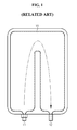
- FIG. 1 is a diagram illustrating the design of a cooling channel 10 according to a related art.
- the cooling channel 10 for cooling a secondary battery is illustrated.
- a refrigerant flowing in the cooling channel 10 enters an inlet 11 and exits an outlet 12.
- the secondary battery is more cooled at the inlet 11 side and is less cooled at the outlet 12 side. That is, the farther from the inlet 11 and closer to the outlet 12 the location is, the higher the temperature of the coolant is, so the cooling efficiency reduces.
- the above problem of the related art causes a temperature gradient of the secondary battery, and the temperature gradient of the secondary battery leads to a performance gradient of the secondary battery. Finally, it connects with performance deterioration of a system such as a battery pack including the secondary battery. Therefore, there is a need for the design of a cooling channel to provide a uniform cooling effect.
- the present disclosure is designed to address the above issue of the related art, and therefore, the present disclosure is directed to providing a heat sink with two or more separated channels.
- a heat sink includes a cooling channel through which a refrigerant passes to cool a secondary battery by an indirect cooling method, the secondary battery including a cell assembly in which at least two unit cells are stacked, each unit cell including a positive electrode plate, a separator, and a negative electrode plate, and a plurality of positive and negative electrode tabs protruding from the positive and negative electrode plates of each unit cell is electrically connected to positive and negative leads, respectively, wherein the cooling channel has two or more separated channels, the two or more separated channels have branches inside to allow a coolant to flow in each of the channels, and the branches are vertically arranged.
- the two or more channels separated by dividing an area of the heat sink into halves may be each designed to be responsible for half the cooling, and an overlapping part of the two or more channels may be formed in a multilayer structure by vertically arranging the branches.
- the area of the heat sink may be divided into a part close to the common inlet and a remaining part, and the branches may have a structure in which among the two or more separated channels, a channel for cooling the part close to the common inlet is placed lower and a channel for cooling the remaining part is placed higher.
- the channel for cooling the part close to the common inlet may provide a thermal insulation effect between the part close to the common inlet and the channel for cooling the remaining part.
- the heat sink according to the present disclosure may be an element of an indirect secondary battery cooling apparatus including the heat sink and a cooling fin which comes into contact with one surface of the secondary battery.
- the indirect secondary battery cooling apparatus may be an element of a battery module including the indirect secondary battery cooling apparatus and at least two secondary batteries.
- the battery module according to the present disclosure may be an element of a battery pack including a plurality of battery modules and a battery management system which controls the charge and discharge of the battery modules.
- the battery pack according to the present disclosure may be an element of a battery operating system including the battery pack and a load which is supplied with power from the battery pack.
- the load may be an electrical drive means or a portable device.
- Two or more separated cooling channels according to the present disclosure have a shorter movement distance than a related art.
- a rate at which the temperature rises with the increasing distance from an inlet of the cooling channel is relatively low. That is, the problem of the related art, i.e., the cooling efficiency reduces with the increasing distance from the inlet of the cooling channel, may be solved.
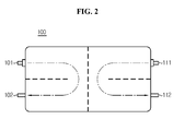
- FIGS. 2 and 3 are cross-sectional views illustrating heat sinks 100 and 200 with two or more separated cooling channels.
- the heat sink according to the present disclosure uses an indirect cooling method to cool a secondary battery.
- heat generated from the secondary battery is transferred to a cooling fin by a contact between the surface of the secondary battery and the cooling fin.
- the cooling fin is connected to a heat sink having a large surface area, and the heat is transferred from the cooling fin to the heat sink.
- the heat sink is cooled by a coolant again.
- the indirect cooling method is a method which cools the secondary battery through the cooling fin and the heat sink, without requiring the coolant to directly pass through the secondary battery.
- the cooling channel formed inside the heat sink should be understood from a cross sectional area of the heat sink.
- inlets 101 and 111 of the two or more cooling channels are formed at opposing locations with respect to the center of the heat sink 100.
- outlets 102 and 112 of the cooling channels may be also formed at opposing locations with respect to the center of the heat sink 100.
- inlets 201 and 211 of the two or more cooling channels are formed at diagonal locations with respect to the center of the heat sink 200.
- outlets 202 and 212 of the cooling channels may be also formed at diagonal locations with respect to the center of the heat sink heat sink 200.
- FIGS. 2 and 3 show that a refrigerant flows in the cooling channel only one time for simplification of the drawings, it should be understood that the internal cooling channel may be variously formed.
- the heat sinks 100 and 200 described with reference to FIGS. 2 and 3 are designed such that a heat sink area is divided into halves, a cooling channel is split into halves, and each channel covers half the cooling.
- a channel length is half the channel length of a traditional heat sink, a maximum distance from the inlets 101 and 111 and 201 and 211 of the cooling channels to a point where heat is generated may be reduced by half.
- an inflow of coolant flows in two halves there is an advantage of reducing a loss of pressure in the same system.
- the present disclosure features two or more separated cooling channels.
- the two or more separated cooling channels have a shorter movement distance than the related art.
- a rate at which the temperature rises with the increasing distance from an inlet of the cooling channel is relatively low. That is, the problem of the related art, i.e., the cooling efficiency reduces with the increasing distance from the inlet of the cooling channel, may be solved.
- the heat sinks 100 and 200 shown in FIGS. 2 and 3 have the increasing number of cooling channel inlets and outlets with the increasing number of separated cooling channels. Accordingly, the number of connection points with a coolant supply device and an amount of work involved therein increases by as much.
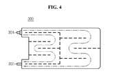
- FIG. 4 is a cross-sectional view illustrating a heat sink 300 with a common inlet and a common outlet.
- FIG. 4 there are found a common inlet 301 and a common outlet 302 for channels, dissimilar to the embodiments of FIGS. 2 and 3 . That is, the heat sink 300 shown in FIG. 4 is characterized in having a common inlet and a common outlet.
- connection points with a device for supplying coolant are necessary.
- the number of connection points with a device for supplying coolant reduces.
- the cooling channels shown in FIG. 4 may be variously formed.
- branches 311 and 321 may be arranged horizontally inside the channels as shown in FIG. 5 .
- channels with a common inlet and a common outlet as in the embodiment shown in FIG. 4 need branches inside the channels to allow a coolant to flow in two or more separated channels.
- FIG. 5 is a see-through perspective view illustrating the branches 311 and 321 arranged horizontally inside the channels.
- the two or more separated channels have the branches 311 and 321 inside to allow a coolant to flow in each of the channels, and the branches 311 and 321 may be horizontally arranged.
- branches 311 and 321 arranged horizontally inside the channels are an unnecessary temperature increase in the coolant.
- the branch indicated by the reference numeral 311 refers to a branch which induces the coolant to move to the channel on the right side among the channels shown in FIG. 4
- the branch indicated by the reference numeral 321 refers to a branch which induces the coolant to move to the channel on the left side among the channels shown in FIG. 4 .
- the heat may be transferred to the coolant flowing in the channel connected to the reference numeral 311, and the channel connected to the reference numeral 311 also increases in temperature while passing through a left heat source part before passing through a right heat source, i.e., an object to be cooled disposed on the right side which is farther than the left heat source.
- a left heat source part before passing through a right heat source, i.e., an object to be cooled disposed on the right side which is farther than the left heat source.
- the coolant in the channel on the right side is unnecessarily at a higher temperature because of having to go farther and turn back than that of the channel connected to the reference numeral 311, i.e., the channel on the left side.
- FIG. 6 is a see-through perspective view illustrating the branches arranged vertically inside the channels according to an exemplary embodiment of the present disclosure.
- the two or more separated channels have the branches 311 and 321 inside to allow the coolant to flow in each of the channels, and the branches 311 and 321 may be vertically arranged.
- branch indicated by the reference numeral 311 refers to a branch which induces the coolant to move to the channel on the right side among the channels shown in FIG. 4
- branch indicated by the reference numeral 321 refers to a branch which induces the coolant to move to the channel on the left side among the channels shown in FIG. 4 .
- the heat sink 300 with the channels of FIG. 6 may cool, for example, two batteries M1 and M2 placed in parallel as shown in FIG. 7 on the side, and for example, the same works for a battery module.
- the left channel of FIG. 4 connected to the reference numeral 321 may be responsible for cooling the battery M1 on the left side (also front side) among the two batteries M1 and M2
- the right channel of FIG. 4 connected to the reference numeral 311 may be responsible for cooling the battery M2 on the right side (also rear side) among the two batteries M1 and M2.
- an overlapping part of the left channel of FIG. 4 connected to the reference numeral 321 and the right channel of FIG. 4 connected to the reference numeral 311 has a multilayer structure of vertical arrangement as shown in FIG. 6 , and a non-overlapping part, i.e., a part where only the right channel of FIG. 4 connected to the reference numeral 311 is present, maintains a single layer.
- the channel connected to the reference numeral 311 does not come into contact with the front battery M1. This is because the channel connected to the reference numeral 321 disposed between the channel connected to the reference numeral 311 and the front battery M1 provides a thermal insulation effect to prevent an initial temperature of the coolant flowing in the channel connected to the reference numeral 311 from increasing due to the front battery M1.
- the cooling performance of the rear battery M2 may be improved and equal cooling rates of the front battery M1 and the rear battery M2 may be achieved, reducing a temperature gradient between the batteries M1 and M2.
- the coolant entering to cool the two batteries M1 and M2 is divided into an upper part and a lower part, so uniform cooling of the batteries placed in parallel is accomplished without interference, thereby providing a performance improvement effect for a battery module including the batteries.
- the heat source disposed immediately below the reference numeral 321 is an object being cooled by the coolant flowing in the channel connected to the reference numeral 321, i.e., the front battery M1.
- the branches when the branches are vertically arranged, an unnecessary temperature increase in a portion of the coolant may be prevented.
- a heat sink is disposed on the side of two batteries placed in parallel to cool the batteries
- various embodiments may be enabled, provided uniform cooling is accomplished without coolant interference between two or more separated channels stacked vertically including a channel responsible for cooling a left part close to a common inlet and a channel responsible for cooling a remaining right part by dividing a heat sink area into halves, even in the case of one object being cooled, i.e., one heat source.
- this vertical arrangement of a multilayer structure may be applied to a multilayer channel structure including a two-layer channel structure, and any shape is available with an internal channel in each layer.
- FIG. 4 presents a heat sink with two separated channels as an example for convenience of understanding and simplification of the drawings
- the heat sink according to the present disclosure may have two or more separated cooling channels as described above.
- the heat sink according to the present disclosure may be an element of an indirect secondary battery cooling apparatus including the heat sink and a cooling fin in contact with one surface of a secondary battery.
- the indirect secondary battery cooling apparatus may be an element of a battery module including the indirect secondary battery cooling apparatus and at least two secondary batteries.
- the battery module according to the present disclosure may be an element of a battery pack including a plurality of battery modules and a battery management system which controls the charge and discharge of the battery modules.
- the battery pack according to the present disclosure may be an element of a battery operating system including the battery pack and a load which is supplied with power from the battery pack.
- the battery operating system may be, for example, an electric vehicle (EV), a hybrid electric vehicle (HEV), an electric bike, a power tool, an energy storage system, an uninterruptible power supply (UPS), a portable computer, a mobile phone, a portable audio player, or a portable video player, and the load may be a motor that generates a rotational force by power supplied from a battery pack, or a power inverter circuit that inverts power supplied from a battery pack to power required for various circuit components.
- EV electric vehicle
- HEV hybrid electric vehicle
- UPS uninterruptible power supply
- the load may be a motor that generates a rotational force by power supplied from a battery pack, or a power inverter circuit that inverts power supplied from a battery pack to power required for various circuit components.
- the heat sink according to the present disclosure does not limit the scope of the invention by the secondary battery being cooled.
- the secondary battery includes a cell assembly in which at least two unit cells are stacked, each unit cell including a positive electrode plate, a separator, and a negative electrode plate, and a plurality of positive and negative electrode tabs protruding from the positive and negative electrode plates of each unit cell is electrically connected to positive and negative leads, respectively.
- the positive electrode plate is primarily made from aluminum.
- the positive electrode plate may be made from stainless steel, nickel, titanium, baked carbon, or aluminum or stainless steel treated with carbon, nickel, titanium, or silver on the surface.
- the positive electrode plate is not limited to a particular material if it has a high conductivity while not causing a chemical change in the secondary battery.
- the positive electrode tab is provided at a certain area of the positive electrode plate, and may extend from the positive electrode plate.
- the positive electrode tab may be formed by joining a member of a conductive material to a predetermined portion of the positive electrode plate, for example, through welding.
- the positive electrode tab may be formed by coating and drying a positive electrode material on a certain area of a peripheral surface of the positive electrode plate.
- the negative electrode plate corresponding to the positive electrode plate is primarily made from copper.
- the negative electrode plate may be made from stainless steel, aluminum, nickel, titanium, baked carbon, or copper or stainless steel treated with carbon, nickel, titanium, or silver on the surface, and aluminum-cadmium alloys may be also used.
- the negative electrode tab is also provided at a certain area of the negative electrode plate, and similar to the positive electrode tab described above, may extend from the negative electrode plate, and the negative electrode tab may be formed by joining a member of a conductive material to a predetermined portion of the negative electrode plate, for example, through welding, and may be formed by coating and drying a negative electrode material on a certain area of a peripheral surface of the negative electrode plate.
- the positive electrode lead is electrically connected to the positive electrode tab of the positive electrode plate
- the negative electrode lead is electrically connected to the negative electrode tab of the negative electrode plate.
- the positive electrode lead and the negative electrode lead are joined with a plurality of positive electrode tabs and a plurality of negative electrode tabs, respectively.
- the positive electrode plate and the negative electrode plate are coated with a positive electrode active material and a negative electrode active material, respectively.
- the positive electrode active material is a lithium-based active material, and as a typical example, may include metal oxide such as LiCoO 2 , LiNiO 2 , LiMnO 2 , LiMn 2 O 4 , LiFePO 4 , or Li 1+zN i 1-x-y Co x M y O 2 (0 ⁇ x ⁇ 1, 0 ⁇ y ⁇ 1, 0 ⁇ x+y ⁇ 1, 0 ⁇ z ⁇ 1, M denotes a metal such as Al, Sr, Mg, La, and Mn).
- the negative electrode active material is a carbon-based active material, and may include a carbon material such as crystalline carbon, amorphous carbon, carbon complex, and carbon fibers, lithium metals, and lithium alloys.
- the type and chemical composition of the positive electrode active material and the negative electrode active material may change based on the type of the secondary battery, and it should be understood that the above particular example is for illustration only.
- the separator is not limited to a particular type, provided it is made from a porous material.
- the separator may be formed of a porous polymer membrane, for example, a porous polyolefin membrane, polyvinylidene fluoride-co-hexafluoropropylene, polyvinylidene fluoride-trichloroethylene, polymethylmetacrylate, polyacrylonitrile, polyvinylpyrrolidone, polyvinylacetate, ethylene vinyl acetate copolymer, polyethyleneoxide, cellulose acetate, cellulose acetate butylate, cellulose acetate propionate, cyanoethylpullulan, cyanoethylpolyvinylalcohol, cyanoethylcellulose, cyanoethylsucrose, pullulan, carboxyl methyl cellulose, acrylonitrile butadiene styrene copolymer, polyimide, polyethylene terephthalate, poly
- the inorganic particles are preferably inorganic particles having a high dielectric constant greater than or equal to 5, and more preferably, inorganic particles having a high dielectric constant greater than or equal to 10 and a low density. This facilitates the transfer of lithium ions moving in the battery.
- Non-limiting examples of inorganic particles having a high dielectric constant greater than or equal to 5 include Pb(Zr,Ti)O 3 (PZT), Pb 1-x La x Zr 1-y Ti y O 3 (PLZT), Pb(Mg 3 Nb 2/3 )O 3 -PbTiO 3 (PMN-PT), BaTiO 3 , hafnia (HfO 2 ), SrTiO 3 , TiO 2 , Al 2 O 3 , ZrO 2 , SnO 2 , CeO 2 , MgO, CaO, ZnO, Y 2 O 3 , or mixtures thereof.
- PZT Pb 1-x La x Zr 1-y Ti y O 3
- PMN-PT Pb(Mg 3 Nb 2/3 )O 3 -PbTiO 3
- BaTiO 3 hafnia
- HfO 2 hafnia
- SrTiO 3 TiO 2 , Al 2 O
- the cell assembly may have a simple stack structure of a plurality of unit cells with an insulating membrane interposed between the unit cells.
- the cell assembly may have a stack folding structure in which unit cells are arranged at an optimum interval on an upper surface and/or a lower surface of an insulating membrane and the insulating membrane is folded in one direction together with the unit cells, so the unit cells are inserted between the folded insulating membrane.
- the cell assembly may have a jelly roll structure formed by mounting, on an insulating membrane, a unit cell extending in the shape of a strand and continuously rolling up the unit cell and the insulating membrane together in one direction.
- the insulating membrane may be made from a material that may be employed as the separator. According to circumstances, the insulating membrane may be made from the same material membrane and/or with the same structure as the separator.
Landscapes
- Engineering & Computer Science (AREA)
- Chemical & Material Sciences (AREA)
- Chemical Kinetics & Catalysis (AREA)
- Electrochemistry (AREA)
- General Chemical & Material Sciences (AREA)
- Manufacturing & Machinery (AREA)
- Physics & Mathematics (AREA)
- Thermal Sciences (AREA)
- Mechanical Engineering (AREA)
- General Engineering & Computer Science (AREA)
- Secondary Cells (AREA)
- Battery Mounting, Suspending (AREA)
Priority Applications (1)
| Application Number | Priority Date | Filing Date | Title |
|---|---|---|---|
| PL14854399T PL2933871T3 (pl) | 2013-10-18 | 2014-10-17 | Radiator mający dwa lub więcej oddzielnych kanałów ułożonych pionowo ze wspólnym wlotem i wspólnym wylotem |
Applications Claiming Priority (3)
| Application Number | Priority Date | Filing Date | Title |
|---|---|---|---|
| KR20130124716 | 2013-10-18 | ||
| KR1020140140059A KR101642326B1 (ko) | 2013-10-18 | 2014-10-16 | 수직 배치된 공통 출입구가 형성된 2이상의 분리된 유로를 가진 히트싱크 |
| PCT/KR2014/009787 WO2015057014A1 (fr) | 2013-10-18 | 2014-10-17 | Dissipateur de chaleur ayant au moins deux canaux d'écoulement séparés comportant un orifice d'entrée/de sortie commun agencé verticalement qui est formé dans ces derniers |
Publications (3)
| Publication Number | Publication Date |
|---|---|
| EP2933871A1 true EP2933871A1 (fr) | 2015-10-21 |
| EP2933871A4 EP2933871A4 (fr) | 2016-07-13 |
| EP2933871B1 EP2933871B1 (fr) | 2020-08-12 |
Family
ID=53037369
Family Applications (1)
| Application Number | Title | Priority Date | Filing Date |
|---|---|---|---|
| EP14854399.4A Active EP2933871B1 (fr) | 2013-10-18 | 2014-10-17 | Dissipateur de chaleur avec deux canaux séparés verticalement agencés avec une entrée commune et une sortie commune |
Country Status (5)
| Country | Link |
|---|---|
| US (1) | US9692094B2 (fr) |
| EP (1) | EP2933871B1 (fr) |
| KR (1) | KR101642326B1 (fr) |
| PL (1) | PL2933871T3 (fr) |
| WO (1) | WO2015057014A1 (fr) |
Families Citing this family (14)
| Publication number | Priority date | Publication date | Assignee | Title |
|---|---|---|---|---|
| KR101990590B1 (ko) * | 2015-08-17 | 2019-06-18 | 주식회사 엘지화학 | 배터리 모듈, 배터리 모듈을 포함하는 배터리 팩 및 배터리 팩을 포함하는 자동차 |
| FR3058575A1 (fr) | 2016-11-07 | 2018-05-11 | Peugeot Citroen Automobiles Sa | Batterie a modules de cellule(s) electrochimique(s) separes par des plaques d'echange externes, et systeme associe |
| DE102016125697A1 (de) * | 2016-12-23 | 2018-06-28 | Benteler Automobiltechnik Gmbh | Batteriehalterung für ein Fahrzeug |
| EP3413393A1 (fr) * | 2017-06-07 | 2018-12-12 | Robert Bosch GmbH | Ensemble d'électrode pour un module de batterie |
| KR102389184B1 (ko) | 2018-09-13 | 2022-04-20 | 주식회사 엘지에너지솔루션 | 배터리 모듈, 이러한 배터리 모듈을 포함하는 배터리 팩 및 이러한 배터리 팩을 포함하는 자동차 |
| KR102158364B1 (ko) | 2018-10-15 | 2020-09-21 | 주식회사 엘지화학 | 배터리 모듈, 이러한 배터리 모듈을 포함하는 배터리 팩 및 이러한 배터리 팩을 포함하는 자동차 |
| CN111322794A (zh) * | 2018-12-14 | 2020-06-23 | 丹佛斯有限公司 | 换热器和空调系统 |
| US11085699B2 (en) | 2019-11-19 | 2021-08-10 | Dana Canada Corporation | Heat exchanger with crossover passages for cold fluid distribution |
| DE102019220406A1 (de) * | 2019-12-20 | 2021-06-24 | Hanon Systems | Wärmeübertrager und Wärmeübertrageranordnung mit mehreren Wärmeübertragern |
| CN111442685B (zh) * | 2020-04-29 | 2021-05-18 | 周利杰 | 一种凝汽器铜管内除垢系统 |
| CN113013529B (zh) * | 2021-02-18 | 2022-07-26 | 中国第一汽车股份有限公司 | 一种风冷电池冷却系统及冷却流道设计方法 |
| US20220328921A1 (en) * | 2021-04-08 | 2022-10-13 | Aurora Flight Sciences Corporation, a subsidiary of The Boeing Company | Batteries, battery components, and related methods and apparatus for mitigating a thermal runaway event of a battery |
| FR3134655B1 (fr) | 2022-04-13 | 2024-03-01 | Psa Automobiles Sa | Dispositif d’échange thermique allégé pour une batterie d’un système |
| DE102022133232A1 (de) | 2022-12-14 | 2024-06-20 | Audi Aktiengesellschaft | Kühlanordnung zur beidseitigen Kühlung einer Batterieeinheit und Batteriemodul für ein Kraftfahrzeug |
Family Cites Families (20)
| Publication number | Priority date | Publication date | Assignee | Title |
|---|---|---|---|---|
| KR940010453A (ko) * | 1992-10-01 | 1994-05-26 | 가나이 쯔도무 | 전기 자동차의 냉각 시스템 및 이것에 이용되는 전기 모터 |
| JP3462598B2 (ja) | 1994-11-08 | 2003-11-05 | 浜松ホトニクス株式会社 | ヒートシンク付レーザダイオードアレイ |
| US7264901B2 (en) * | 1998-08-23 | 2007-09-04 | Ovonic Battery Company, Inc. | Monoblock battery |
| JP2001024126A (ja) | 1999-07-09 | 2001-01-26 | Fuji Electric Co Ltd | 直膨式コールドプレート |
| JP4913333B2 (ja) | 2003-06-13 | 2012-04-11 | 古河電気工業株式会社 | ヒートシンクおよび均一な冷却方法 |
| KR100853621B1 (ko) | 2004-10-26 | 2008-08-25 | 주식회사 엘지화학 | 전지팩의 냉각 시스템 |
| KR20060102851A (ko) * | 2005-03-25 | 2006-09-28 | 삼성에스디아이 주식회사 | 이차 전지 모듈 |
| KR100892046B1 (ko) * | 2006-09-18 | 2009-04-07 | 주식회사 엘지화학 | 전지모듈 및 그것을 포함하고 있는 중대형 전지팩 |
| CN102511091B (zh) * | 2009-06-18 | 2014-09-24 | 江森自控帅福得先进能源动力系统有限责任公司 | 具有带有热管理部件的电池单元托盘的电池模块 |
| DE102010056204A1 (de) * | 2010-03-26 | 2011-09-29 | Daimler Ag | Temperierelement für eine Batterie |
| KR101205181B1 (ko) | 2010-05-18 | 2012-11-27 | 주식회사 엘지화학 | 신규한 구조의 냉각부재와 이를 포함하는 전지모듈 |
| DE102010032899A1 (de) * | 2010-07-30 | 2012-02-02 | Valeo Klimasysteme Gmbh | Kühlvorrichtung für eine Fahrzeugbatterie sowie Fahrzeugbatteriebaugruppe mit einer solchen Kühlvorrichtung |
| KR101177887B1 (ko) | 2010-11-22 | 2012-08-29 | 주식회사 한국쿨러 | 히트 싱크를 이용한 전기 차량용 전지셀 모듈 |
| KR101293971B1 (ko) * | 2011-01-26 | 2013-08-07 | 주식회사 엘지화학 | 냉각 성능이 향상된 냉각부재와 이를 포함하는 전지모듈 |
| JP2013037869A (ja) | 2011-08-08 | 2013-02-21 | Panasonic Corp | 冷却装置および蓄電池装置 |
| US8835039B2 (en) * | 2011-10-21 | 2014-09-16 | Avl Powertrain Engineering, Inc. | Battery cooling plate and cooling system |
| DE102011086246A1 (de) * | 2011-11-14 | 2013-05-16 | Sb Limotive Company Ltd. | Batteriesystem und Kraftfahrzeug |
| KR101750066B1 (ko) | 2011-12-02 | 2017-06-23 | 에스케이이노베이션 주식회사 | 수냉식 이차전지 |
| KR20130104660A (ko) | 2012-03-15 | 2013-09-25 | 에스케이이노베이션 주식회사 | 배터리 모듈 |
| DE102012005870A1 (de) * | 2012-03-23 | 2013-09-26 | Valeo Klimasysteme Gmbh | Kühlvorrichtung für eine Fahrzeugbatterie sowie Fahrzeugbatterie mit Kühlvorrichtung |
-
2014
- 2014-10-16 KR KR1020140140059A patent/KR101642326B1/ko active IP Right Grant
- 2014-10-17 EP EP14854399.4A patent/EP2933871B1/fr active Active
- 2014-10-17 US US14/651,745 patent/US9692094B2/en active Active
- 2014-10-17 PL PL14854399T patent/PL2933871T3/pl unknown
- 2014-10-17 WO PCT/KR2014/009787 patent/WO2015057014A1/fr active Application Filing
Also Published As
| Publication number | Publication date |
|---|---|
| EP2933871A4 (fr) | 2016-07-13 |
| KR20150045377A (ko) | 2015-04-28 |
| EP2933871B1 (fr) | 2020-08-12 |
| KR101642326B1 (ko) | 2016-07-26 |
| WO2015057014A1 (fr) | 2015-04-23 |
| PL2933871T3 (pl) | 2020-12-14 |
| US20150303537A1 (en) | 2015-10-22 |
| US9692094B2 (en) | 2017-06-27 |
Similar Documents
| Publication | Publication Date | Title |
|---|---|---|
| EP2933871B1 (fr) | Dissipateur de chaleur avec deux canaux séparés verticalement agencés avec une entrée commune et une sortie commune | |
| US10044078B2 (en) | Heat sink with two or more separated channels including insulation material | |
| EP2933870B1 (fr) | Dissipateur de chaleur ayant deux canals d'écoulement distincts | |
| JP5292663B2 (ja) | 組電池及び該組電池を搭載した車輌 | |
| KR101650417B1 (ko) | 양극 집전체에 간헐적 무지부가 형성된 젤리 롤 형태 전극 조립체를 가진 이차전지 | |
| US10103415B2 (en) | Battery pack with intracell heat conducting members | |
| EP3387698B1 (fr) | Batterie à configuration variable de cellules électrochimiques | |
| KR101297866B1 (ko) | 전극조립체 및 이를 포함하는 리튬 이차전지 | |
| JP2006079987A (ja) | ハイブリッド電池システム | |
| US10957955B2 (en) | Battery module and battery pack including the same | |
| KR101760865B1 (ko) | 열전소자를 이용한 배터리팩 자가 냉각 방법 및 시스템 | |
| KR20150045245A (ko) | 공통 출입구가 형성된 2이상의 분리된 유로를 가진 히트싱크 | |
| US9590224B2 (en) | Secondary battery and manufacturing method thereof | |
| KR101668356B1 (ko) | 스택-폴딩형 전극 조립체 및 그 제조 방법 | |
| US10680297B2 (en) | Tab cooling for pouch cell | |
| KR20150072107A (ko) | 미 열융착 라인을 통해 파우치형 케이스의 주변 부위가 접힌 이차전지 | |
| JP2008287916A (ja) | 電池パック | |
| US9437898B2 (en) | Secondary battery including plurality of electrode assemblies | |
| CN107278339A (zh) | 电池单池和电池系统 |
Legal Events
| Date | Code | Title | Description |
|---|---|---|---|
| PUAI | Public reference made under article 153(3) epc to a published international application that has entered the european phase |
Free format text: ORIGINAL CODE: 0009012 |
|
| 17P | Request for examination filed |
Effective date: 20150715 |
|
| AK | Designated contracting states |
Kind code of ref document: A1 Designated state(s): AL AT BE BG CH CY CZ DE DK EE ES FI FR GB GR HR HU IE IS IT LI LT LU LV MC MK MT NL NO PL PT RO RS SE SI SK SM TR |
|
| AX | Request for extension of the european patent |
Extension state: BA ME |
|
| A4 | Supplementary search report drawn up and despatched |
Effective date: 20160609 |
|
| RIC1 | Information provided on ipc code assigned before grant |
Ipc: H01M 10/60 20140101AFI20160603BHEP Ipc: H01M 10/6554 20140101ALI20160603BHEP Ipc: H01M 2/10 20060101ALI20160603BHEP Ipc: H01M 10/65 20140101ALI20160603BHEP Ipc: H01M 10/6556 20140101ALI20160603BHEP |
|
| DAX | Request for extension of the european patent (deleted) | ||
| STAA | Information on the status of an ep patent application or granted ep patent |
Free format text: STATUS: EXAMINATION IS IN PROGRESS |
|
| 17Q | First examination report despatched |
Effective date: 20170816 |
|
| GRAP | Despatch of communication of intention to grant a patent |
Free format text: ORIGINAL CODE: EPIDOSNIGR1 |
|
| STAA | Information on the status of an ep patent application or granted ep patent |
Free format text: STATUS: GRANT OF PATENT IS INTENDED |
|
| INTG | Intention to grant announced |
Effective date: 20200429 |
|
| GRAS | Grant fee paid |
Free format text: ORIGINAL CODE: EPIDOSNIGR3 |
|
| GRAA | (expected) grant |
Free format text: ORIGINAL CODE: 0009210 |
|
| STAA | Information on the status of an ep patent application or granted ep patent |
Free format text: STATUS: THE PATENT HAS BEEN GRANTED |
|
| AK | Designated contracting states |
Kind code of ref document: B1 Designated state(s): AL AT BE BG CH CY CZ DE DK EE ES FI FR GB GR HR HU IE IS IT LI LT LU LV MC MK MT NL NO PL PT RO RS SE SI SK SM TR |
|
| RAP1 | Party data changed (applicant data changed or rights of an application transferred) |
Owner name: LG CHEM, LTD. |
|
| REG | Reference to a national code |
Ref country code: CH Ref legal event code: EP |
|
| REG | Reference to a national code |
Ref country code: DE Ref legal event code: R096 Ref document number: 602014068984 Country of ref document: DE |
|
| REG | Reference to a national code |
Ref country code: IE Ref legal event code: FG4D |
|
| REG | Reference to a national code |
Ref country code: AT Ref legal event code: REF Ref document number: 1302447 Country of ref document: AT Kind code of ref document: T Effective date: 20200915 |
|
| REG | Reference to a national code |
Ref country code: LT Ref legal event code: MG4D |
|
| REG | Reference to a national code |
Ref country code: NL Ref legal event code: MP Effective date: 20200812 |
|
| PG25 | Lapsed in a contracting state [announced via postgrant information from national office to epo] |
Ref country code: LT Free format text: LAPSE BECAUSE OF FAILURE TO SUBMIT A TRANSLATION OF THE DESCRIPTION OR TO PAY THE FEE WITHIN THE PRESCRIBED TIME-LIMIT Effective date: 20200812 Ref country code: HR Free format text: LAPSE BECAUSE OF FAILURE TO SUBMIT A TRANSLATION OF THE DESCRIPTION OR TO PAY THE FEE WITHIN THE PRESCRIBED TIME-LIMIT Effective date: 20200812 Ref country code: NO Free format text: LAPSE BECAUSE OF FAILURE TO SUBMIT A TRANSLATION OF THE DESCRIPTION OR TO PAY THE FEE WITHIN THE PRESCRIBED TIME-LIMIT Effective date: 20201112 Ref country code: SE Free format text: LAPSE BECAUSE OF FAILURE TO SUBMIT A TRANSLATION OF THE DESCRIPTION OR TO PAY THE FEE WITHIN THE PRESCRIBED TIME-LIMIT Effective date: 20200812 Ref country code: GR Free format text: LAPSE BECAUSE OF FAILURE TO SUBMIT A TRANSLATION OF THE DESCRIPTION OR TO PAY THE FEE WITHIN THE PRESCRIBED TIME-LIMIT Effective date: 20201113 Ref country code: FI Free format text: LAPSE BECAUSE OF FAILURE TO SUBMIT A TRANSLATION OF THE DESCRIPTION OR TO PAY THE FEE WITHIN THE PRESCRIBED TIME-LIMIT Effective date: 20200812 Ref country code: ES Free format text: LAPSE BECAUSE OF FAILURE TO SUBMIT A TRANSLATION OF THE DESCRIPTION OR TO PAY THE FEE WITHIN THE PRESCRIBED TIME-LIMIT Effective date: 20200812 Ref country code: BG Free format text: LAPSE BECAUSE OF FAILURE TO SUBMIT A TRANSLATION OF THE DESCRIPTION OR TO PAY THE FEE WITHIN THE PRESCRIBED TIME-LIMIT Effective date: 20201112 |
|
| REG | Reference to a national code |
Ref country code: AT Ref legal event code: MK05 Ref document number: 1302447 Country of ref document: AT Kind code of ref document: T Effective date: 20200812 |
|
| PG25 | Lapsed in a contracting state [announced via postgrant information from national office to epo] |
Ref country code: NL Free format text: LAPSE BECAUSE OF FAILURE TO SUBMIT A TRANSLATION OF THE DESCRIPTION OR TO PAY THE FEE WITHIN THE PRESCRIBED TIME-LIMIT Effective date: 20200812 Ref country code: LV Free format text: LAPSE BECAUSE OF FAILURE TO SUBMIT A TRANSLATION OF THE DESCRIPTION OR TO PAY THE FEE WITHIN THE PRESCRIBED TIME-LIMIT Effective date: 20200812 Ref country code: RS Free format text: LAPSE BECAUSE OF FAILURE TO SUBMIT A TRANSLATION OF THE DESCRIPTION OR TO PAY THE FEE WITHIN THE PRESCRIBED TIME-LIMIT Effective date: 20200812 Ref country code: IS Free format text: LAPSE BECAUSE OF FAILURE TO SUBMIT A TRANSLATION OF THE DESCRIPTION OR TO PAY THE FEE WITHIN THE PRESCRIBED TIME-LIMIT Effective date: 20201212 |
|
| PG25 | Lapsed in a contracting state [announced via postgrant information from national office to epo] |
Ref country code: EE Free format text: LAPSE BECAUSE OF FAILURE TO SUBMIT A TRANSLATION OF THE DESCRIPTION OR TO PAY THE FEE WITHIN THE PRESCRIBED TIME-LIMIT Effective date: 20200812 Ref country code: SM Free format text: LAPSE BECAUSE OF FAILURE TO SUBMIT A TRANSLATION OF THE DESCRIPTION OR TO PAY THE FEE WITHIN THE PRESCRIBED TIME-LIMIT Effective date: 20200812 Ref country code: RO Free format text: LAPSE BECAUSE OF FAILURE TO SUBMIT A TRANSLATION OF THE DESCRIPTION OR TO PAY THE FEE WITHIN THE PRESCRIBED TIME-LIMIT Effective date: 20200812 Ref country code: DK Free format text: LAPSE BECAUSE OF FAILURE TO SUBMIT A TRANSLATION OF THE DESCRIPTION OR TO PAY THE FEE WITHIN THE PRESCRIBED TIME-LIMIT Effective date: 20200812 Ref country code: CZ Free format text: LAPSE BECAUSE OF FAILURE TO SUBMIT A TRANSLATION OF THE DESCRIPTION OR TO PAY THE FEE WITHIN THE PRESCRIBED TIME-LIMIT Effective date: 20200812 |
|
| REG | Reference to a national code |
Ref country code: DE Ref legal event code: R097 Ref document number: 602014068984 Country of ref document: DE |
|
| PG25 | Lapsed in a contracting state [announced via postgrant information from national office to epo] |
Ref country code: AT Free format text: LAPSE BECAUSE OF FAILURE TO SUBMIT A TRANSLATION OF THE DESCRIPTION OR TO PAY THE FEE WITHIN THE PRESCRIBED TIME-LIMIT Effective date: 20200812 Ref country code: AL Free format text: LAPSE BECAUSE OF FAILURE TO SUBMIT A TRANSLATION OF THE DESCRIPTION OR TO PAY THE FEE WITHIN THE PRESCRIBED TIME-LIMIT Effective date: 20200812 |
|
| REG | Reference to a national code |
Ref country code: CH Ref legal event code: PL |
|
| PLBE | No opposition filed within time limit |
Free format text: ORIGINAL CODE: 0009261 |
|
| STAA | Information on the status of an ep patent application or granted ep patent |
Free format text: STATUS: NO OPPOSITION FILED WITHIN TIME LIMIT |
|
| PG25 | Lapsed in a contracting state [announced via postgrant information from national office to epo] |
Ref country code: LU Free format text: LAPSE BECAUSE OF NON-PAYMENT OF DUE FEES Effective date: 20201017 Ref country code: MC Free format text: LAPSE BECAUSE OF FAILURE TO SUBMIT A TRANSLATION OF THE DESCRIPTION OR TO PAY THE FEE WITHIN THE PRESCRIBED TIME-LIMIT Effective date: 20200812 Ref country code: SK Free format text: LAPSE BECAUSE OF FAILURE TO SUBMIT A TRANSLATION OF THE DESCRIPTION OR TO PAY THE FEE WITHIN THE PRESCRIBED TIME-LIMIT Effective date: 20200812 |
|
| REG | Reference to a national code |
Ref country code: BE Ref legal event code: MM Effective date: 20201031 |
|
| 26N | No opposition filed |
Effective date: 20210514 |
|
| PG25 | Lapsed in a contracting state [announced via postgrant information from national office to epo] |
Ref country code: IT Free format text: LAPSE BECAUSE OF FAILURE TO SUBMIT A TRANSLATION OF THE DESCRIPTION OR TO PAY THE FEE WITHIN THE PRESCRIBED TIME-LIMIT Effective date: 20200812 |
|
| PG25 | Lapsed in a contracting state [announced via postgrant information from national office to epo] |
Ref country code: SI Free format text: LAPSE BECAUSE OF FAILURE TO SUBMIT A TRANSLATION OF THE DESCRIPTION OR TO PAY THE FEE WITHIN THE PRESCRIBED TIME-LIMIT Effective date: 20200812 Ref country code: LI Free format text: LAPSE BECAUSE OF NON-PAYMENT OF DUE FEES Effective date: 20201031 Ref country code: CH Free format text: LAPSE BECAUSE OF NON-PAYMENT OF DUE FEES Effective date: 20201031 Ref country code: BE Free format text: LAPSE BECAUSE OF NON-PAYMENT OF DUE FEES Effective date: 20201031 |
|
| PG25 | Lapsed in a contracting state [announced via postgrant information from national office to epo] |
Ref country code: IE Free format text: LAPSE BECAUSE OF NON-PAYMENT OF DUE FEES Effective date: 20201017 |
|
| PG25 | Lapsed in a contracting state [announced via postgrant information from national office to epo] |
Ref country code: TR Free format text: LAPSE BECAUSE OF FAILURE TO SUBMIT A TRANSLATION OF THE DESCRIPTION OR TO PAY THE FEE WITHIN THE PRESCRIBED TIME-LIMIT Effective date: 20200812 Ref country code: MT Free format text: LAPSE BECAUSE OF FAILURE TO SUBMIT A TRANSLATION OF THE DESCRIPTION OR TO PAY THE FEE WITHIN THE PRESCRIBED TIME-LIMIT Effective date: 20200812 Ref country code: CY Free format text: LAPSE BECAUSE OF FAILURE TO SUBMIT A TRANSLATION OF THE DESCRIPTION OR TO PAY THE FEE WITHIN THE PRESCRIBED TIME-LIMIT Effective date: 20200812 |
|
| PG25 | Lapsed in a contracting state [announced via postgrant information from national office to epo] |
Ref country code: MK Free format text: LAPSE BECAUSE OF FAILURE TO SUBMIT A TRANSLATION OF THE DESCRIPTION OR TO PAY THE FEE WITHIN THE PRESCRIBED TIME-LIMIT Effective date: 20200812 |
|
| PG25 | Lapsed in a contracting state [announced via postgrant information from national office to epo] |
Ref country code: PT Free format text: LAPSE BECAUSE OF FAILURE TO SUBMIT A TRANSLATION OF THE DESCRIPTION OR TO PAY THE FEE WITHIN THE PRESCRIBED TIME-LIMIT Effective date: 20200812 |
|
| REG | Reference to a national code |
Ref country code: DE Ref legal event code: R081 Ref document number: 602014068984 Country of ref document: DE Owner name: LG ENERGY SOLUTION, LTD., KR Free format text: FORMER OWNER: LG CHEM, LTD., SEOUL, KR |
|
| P01 | Opt-out of the competence of the unified patent court (upc) registered |
Effective date: 20230512 |
|
| REG | Reference to a national code |
Ref country code: GB Ref legal event code: 732E Free format text: REGISTERED BETWEEN 20230824 AND 20230831 |
|
| PGFP | Annual fee paid to national office [announced via postgrant information from national office to epo] |
Ref country code: PL Payment date: 20230921 Year of fee payment: 10 |
|
| PGFP | Annual fee paid to national office [announced via postgrant information from national office to epo] |
Ref country code: DE Payment date: 20230920 Year of fee payment: 10 |
|
| PGFP | Annual fee paid to national office [announced via postgrant information from national office to epo] |
Ref country code: GB Payment date: 20240920 Year of fee payment: 11 |
|
| PGFP | Annual fee paid to national office [announced via postgrant information from national office to epo] |
Ref country code: FR Payment date: 20240925 Year of fee payment: 11 |