EP2933856A1 - Wiederaufladbare batterie mit stromverteilungselement - Google Patents
Wiederaufladbare batterie mit stromverteilungselement Download PDFInfo
- Publication number
- EP2933856A1 EP2933856A1 EP15158336.6A EP15158336A EP2933856A1 EP 2933856 A1 EP2933856 A1 EP 2933856A1 EP 15158336 A EP15158336 A EP 15158336A EP 2933856 A1 EP2933856 A1 EP 2933856A1
- Authority
- EP
- European Patent Office
- Prior art keywords
- current collecting
- collecting member
- case
- rechargeable battery
- electrode
- Prior art date
- Legal status (The legal status is an assumption and is not a legal conclusion. Google has not performed a legal analysis and makes no representation as to the accuracy of the status listed.)
- Granted
Links
Images






Classifications
-
- H—ELECTRICITY
- H01—ELECTRIC ELEMENTS
- H01M—PROCESSES OR MEANS, e.g. BATTERIES, FOR THE DIRECT CONVERSION OF CHEMICAL ENERGY INTO ELECTRICAL ENERGY
- H01M10/00—Secondary cells; Manufacture thereof
- H01M10/04—Construction or manufacture in general
- H01M10/0413—Large-sized flat cells or batteries for motive or stationary systems with plate-like electrodes
-
- H—ELECTRICITY
- H01—ELECTRIC ELEMENTS
- H01M—PROCESSES OR MEANS, e.g. BATTERIES, FOR THE DIRECT CONVERSION OF CHEMICAL ENERGY INTO ELECTRICAL ENERGY
- H01M50/00—Constructional details or processes of manufacture of the non-active parts of electrochemical cells other than fuel cells, e.g. hybrid cells
- H01M50/50—Current conducting connections for cells or batteries
- H01M50/572—Means for preventing undesired use or discharge
-
- H—ELECTRICITY
- H01—ELECTRIC ELEMENTS
- H01M—PROCESSES OR MEANS, e.g. BATTERIES, FOR THE DIRECT CONVERSION OF CHEMICAL ENERGY INTO ELECTRICAL ENERGY
- H01M10/00—Secondary cells; Manufacture thereof
- H01M10/05—Accumulators with non-aqueous electrolyte
- H01M10/058—Construction or manufacture
- H01M10/0587—Construction or manufacture of accumulators having only wound construction elements, i.e. wound positive electrodes, wound negative electrodes and wound separators
-
- H—ELECTRICITY
- H01—ELECTRIC ELEMENTS
- H01M—PROCESSES OR MEANS, e.g. BATTERIES, FOR THE DIRECT CONVERSION OF CHEMICAL ENERGY INTO ELECTRICAL ENERGY
- H01M50/00—Constructional details or processes of manufacture of the non-active parts of electrochemical cells other than fuel cells, e.g. hybrid cells
- H01M50/10—Primary casings; Jackets or wrappings
- H01M50/147—Lids or covers
- H01M50/148—Lids or covers characterised by their shape
- H01M50/15—Lids or covers characterised by their shape for prismatic or rectangular cells
-
- H—ELECTRICITY
- H01—ELECTRIC ELEMENTS
- H01M—PROCESSES OR MEANS, e.g. BATTERIES, FOR THE DIRECT CONVERSION OF CHEMICAL ENERGY INTO ELECTRICAL ENERGY
- H01M50/00—Constructional details or processes of manufacture of the non-active parts of electrochemical cells other than fuel cells, e.g. hybrid cells
- H01M50/10—Primary casings; Jackets or wrappings
- H01M50/147—Lids or covers
- H01M50/155—Lids or covers characterised by the material
-
- H—ELECTRICITY
- H01—ELECTRIC ELEMENTS
- H01M—PROCESSES OR MEANS, e.g. BATTERIES, FOR THE DIRECT CONVERSION OF CHEMICAL ENERGY INTO ELECTRICAL ENERGY
- H01M50/00—Constructional details or processes of manufacture of the non-active parts of electrochemical cells other than fuel cells, e.g. hybrid cells
- H01M50/10—Primary casings; Jackets or wrappings
- H01M50/172—Arrangements of electric connectors penetrating the casing
- H01M50/174—Arrangements of electric connectors penetrating the casing adapted for the shape of the cells
- H01M50/176—Arrangements of electric connectors penetrating the casing adapted for the shape of the cells for prismatic or rectangular cells
-
- H—ELECTRICITY
- H01—ELECTRIC ELEMENTS
- H01M—PROCESSES OR MEANS, e.g. BATTERIES, FOR THE DIRECT CONVERSION OF CHEMICAL ENERGY INTO ELECTRICAL ENERGY
- H01M50/00—Constructional details or processes of manufacture of the non-active parts of electrochemical cells other than fuel cells, e.g. hybrid cells
- H01M50/50—Current conducting connections for cells or batteries
- H01M50/528—Fixed electrical connections, i.e. not intended for disconnection
-
- H—ELECTRICITY
- H01—ELECTRIC ELEMENTS
- H01M—PROCESSES OR MEANS, e.g. BATTERIES, FOR THE DIRECT CONVERSION OF CHEMICAL ENERGY INTO ELECTRICAL ENERGY
- H01M50/00—Constructional details or processes of manufacture of the non-active parts of electrochemical cells other than fuel cells, e.g. hybrid cells
- H01M50/50—Current conducting connections for cells or batteries
- H01M50/531—Electrode connections inside a battery casing
- H01M50/536—Electrode connections inside a battery casing characterised by the method of fixing the leads to the electrodes, e.g. by welding
-
- H—ELECTRICITY
- H01—ELECTRIC ELEMENTS
- H01M—PROCESSES OR MEANS, e.g. BATTERIES, FOR THE DIRECT CONVERSION OF CHEMICAL ENERGY INTO ELECTRICAL ENERGY
- H01M50/00—Constructional details or processes of manufacture of the non-active parts of electrochemical cells other than fuel cells, e.g. hybrid cells
- H01M50/50—Current conducting connections for cells or batteries
- H01M50/531—Electrode connections inside a battery casing
- H01M50/538—Connection of several leads or tabs of wound or folded electrode stacks
-
- H—ELECTRICITY
- H01—ELECTRIC ELEMENTS
- H01M—PROCESSES OR MEANS, e.g. BATTERIES, FOR THE DIRECT CONVERSION OF CHEMICAL ENERGY INTO ELECTRICAL ENERGY
- H01M50/00—Constructional details or processes of manufacture of the non-active parts of electrochemical cells other than fuel cells, e.g. hybrid cells
- H01M50/50—Current conducting connections for cells or batteries
- H01M50/531—Electrode connections inside a battery casing
- H01M50/54—Connection of several leads or tabs of plate-like electrode stacks, e.g. electrode pole straps or bridges
-
- H—ELECTRICITY
- H01—ELECTRIC ELEMENTS
- H01M—PROCESSES OR MEANS, e.g. BATTERIES, FOR THE DIRECT CONVERSION OF CHEMICAL ENERGY INTO ELECTRICAL ENERGY
- H01M50/00—Constructional details or processes of manufacture of the non-active parts of electrochemical cells other than fuel cells, e.g. hybrid cells
- H01M50/50—Current conducting connections for cells or batteries
- H01M50/543—Terminals
- H01M50/545—Terminals formed by the casing of the cells
-
- H—ELECTRICITY
- H01—ELECTRIC ELEMENTS
- H01M—PROCESSES OR MEANS, e.g. BATTERIES, FOR THE DIRECT CONVERSION OF CHEMICAL ENERGY INTO ELECTRICAL ENERGY
- H01M50/00—Constructional details or processes of manufacture of the non-active parts of electrochemical cells other than fuel cells, e.g. hybrid cells
- H01M50/50—Current conducting connections for cells or batteries
- H01M50/572—Means for preventing undesired use or discharge
- H01M50/574—Devices or arrangements for the interruption of current
- H01M50/578—Devices or arrangements for the interruption of current in response to pressure
-
- H—ELECTRICITY
- H01—ELECTRIC ELEMENTS
- H01M—PROCESSES OR MEANS, e.g. BATTERIES, FOR THE DIRECT CONVERSION OF CHEMICAL ENERGY INTO ELECTRICAL ENERGY
- H01M50/00—Constructional details or processes of manufacture of the non-active parts of electrochemical cells other than fuel cells, e.g. hybrid cells
- H01M50/50—Current conducting connections for cells or batteries
- H01M50/572—Means for preventing undesired use or discharge
- H01M50/574—Devices or arrangements for the interruption of current
- H01M50/581—Devices or arrangements for the interruption of current in response to temperature
-
- H—ELECTRICITY
- H01—ELECTRIC ELEMENTS
- H01M—PROCESSES OR MEANS, e.g. BATTERIES, FOR THE DIRECT CONVERSION OF CHEMICAL ENERGY INTO ELECTRICAL ENERGY
- H01M50/00—Constructional details or processes of manufacture of the non-active parts of electrochemical cells other than fuel cells, e.g. hybrid cells
- H01M50/50—Current conducting connections for cells or batteries
- H01M50/572—Means for preventing undesired use or discharge
- H01M50/574—Devices or arrangements for the interruption of current
- H01M50/583—Devices or arrangements for the interruption of current in response to current, e.g. fuses
-
- H—ELECTRICITY
- H01—ELECTRIC ELEMENTS
- H01M—PROCESSES OR MEANS, e.g. BATTERIES, FOR THE DIRECT CONVERSION OF CHEMICAL ENERGY INTO ELECTRICAL ENERGY
- H01M50/00—Constructional details or processes of manufacture of the non-active parts of electrochemical cells other than fuel cells, e.g. hybrid cells
- H01M50/50—Current conducting connections for cells or batteries
- H01M50/572—Means for preventing undesired use or discharge
- H01M50/584—Means for preventing undesired use or discharge for preventing incorrect connections inside or outside the batteries
- H01M50/59—Means for preventing undesired use or discharge for preventing incorrect connections inside or outside the batteries characterised by the protection means
- H01M50/593—Spacers; Insulating plates
-
- H—ELECTRICITY
- H01—ELECTRIC ELEMENTS
- H01M—PROCESSES OR MEANS, e.g. BATTERIES, FOR THE DIRECT CONVERSION OF CHEMICAL ENERGY INTO ELECTRICAL ENERGY
- H01M2200/00—Safety devices for primary or secondary batteries
-
- H—ELECTRICITY
- H01—ELECTRIC ELEMENTS
- H01M—PROCESSES OR MEANS, e.g. BATTERIES, FOR THE DIRECT CONVERSION OF CHEMICAL ENERGY INTO ELECTRICAL ENERGY
- H01M2200/00—Safety devices for primary or secondary batteries
- H01M2200/10—Temperature sensitive devices
- H01M2200/103—Fuse
-
- H—ELECTRICITY
- H01—ELECTRIC ELEMENTS
- H01M—PROCESSES OR MEANS, e.g. BATTERIES, FOR THE DIRECT CONVERSION OF CHEMICAL ENERGY INTO ELECTRICAL ENERGY
- H01M2200/00—Safety devices for primary or secondary batteries
- H01M2200/20—Pressure-sensitive devices
-
- H—ELECTRICITY
- H01—ELECTRIC ELEMENTS
- H01M—PROCESSES OR MEANS, e.g. BATTERIES, FOR THE DIRECT CONVERSION OF CHEMICAL ENERGY INTO ELECTRICAL ENERGY
- H01M2220/00—Batteries for particular applications
- H01M2220/20—Batteries in motive systems, e.g. vehicle, ship, plane
-
- Y—GENERAL TAGGING OF NEW TECHNOLOGICAL DEVELOPMENTS; GENERAL TAGGING OF CROSS-SECTIONAL TECHNOLOGIES SPANNING OVER SEVERAL SECTIONS OF THE IPC; TECHNICAL SUBJECTS COVERED BY FORMER USPC CROSS-REFERENCE ART COLLECTIONS [XRACs] AND DIGESTS
- Y02—TECHNOLOGIES OR APPLICATIONS FOR MITIGATION OR ADAPTATION AGAINST CLIMATE CHANGE
- Y02E—REDUCTION OF GREENHOUSE GAS [GHG] EMISSIONS, RELATED TO ENERGY GENERATION, TRANSMISSION OR DISTRIBUTION
- Y02E60/00—Enabling technologies; Technologies with a potential or indirect contribution to GHG emissions mitigation
- Y02E60/10—Energy storage using batteries
-
- Y—GENERAL TAGGING OF NEW TECHNOLOGICAL DEVELOPMENTS; GENERAL TAGGING OF CROSS-SECTIONAL TECHNOLOGIES SPANNING OVER SEVERAL SECTIONS OF THE IPC; TECHNICAL SUBJECTS COVERED BY FORMER USPC CROSS-REFERENCE ART COLLECTIONS [XRACs] AND DIGESTS
- Y02—TECHNOLOGIES OR APPLICATIONS FOR MITIGATION OR ADAPTATION AGAINST CLIMATE CHANGE
- Y02P—CLIMATE CHANGE MITIGATION TECHNOLOGIES IN THE PRODUCTION OR PROCESSING OF GOODS
- Y02P70/00—Climate change mitigation technologies in the production process for final industrial or consumer products
- Y02P70/50—Manufacturing or production processes characterised by the final manufactured product
Definitions
- Embodiments relate to a rechargeable battery having a current distribution member.
- a rechargeable battery differs from a primary battery in that it can be repeatedly charged and discharged, while the latter is incapable of being recharged.
- a low-capacity rechargeable battery may be used in small portable electronic devices, e.g., mobile phones, notebook computers, and camcorders, and a high-capacity rechargeable battery may be used as, e.g., a power source for driving a motor of hybrid vehicles or the like.
- the high power rechargeable battery may be configured such that a plurality of rechargeable batteries are connected in series for high power so as to be used as a power source for driving a motor of a device requiring a large amount of electric power, e.g., electric vehicles or the like.
- a high-capacity rechargeable battery may include a plurality of rechargeable batteries connected in series, and the rechargeable battery may have a cylindrical shape, a prismatic shape, or the like.
- Embodiments are directed to a rechargeable battery having a current distribution member.
- the embodiments may be realized by providing a rechargeable battery including an electrode assembly including a first electrode and a second electrode; a case accommodating the electrode assembly; a cap assembly coupled with the case, the cap assembly including a terminal; a first current collecting member, the first current collecting member including a fuse portion connecting the terminal with the first electrode, and an electrode bonding portion fixed to the electrode assembly, the fuse portion having a lower melting point than other portions of the first current collecting member; and a current distribution member fixed to the first current collecting member, the current distribution member electrically connecting the first current collecting member with the case.
- the cap assembly may include a cap plate coupled with the case, and a connecting member that electrically connects the terminal with the cap plate.
- the connecting member may be coated with a resistive layer, the resistive layer being formed of a synthetic resin.
- the rechargeable battery may further include a safety member that is between the electrode assembly and the case.
- the safety member may include a safety member side plate that faces a flat side surface of the electrode assembly, and a fixing tab that protrudes from the safety member side plate and that is attached to the electrode bonding portion, a surface of the safety member side plate that faces the electrode assembly including an insulating film thereon.
- the current distribution member may be fixed to the first current collecting member at a connecting path that is between the fuse portion and the electrode assembly.
- the current distribution member may include a current collecting member-fixing portion that is fixed to the first current collecting member, and a case fixing portion that is fixed to the case.
- the first current collecting member may include a terminal bonding portion that is bonded to the terminal, and a current collecting member side plate that is bent from the terminal bonding portion and that connects the terminal bonding portion with the electrode bonding portion.
- the fuse portion may be in the terminal bonding portion.
- the current collecting member-fixing portion may be fixed to the current collecting member side plate.
- the current collecting member-fixing portion may be fixed to the electrode bonding portion.
- the case fixing portion may be fixed to a bottom of the case.
- the case fixing portion may be fixed to a lateral side of the case, the lateral side extending between the cap assembly and a bottom of the case.
- the current distribution member may include two current collecting member-fixing portions that are spaced apart from each other, and a lower portion of the current collecting member side plate may be in a supporting groove that is between the current collecting member-fixing portions.
- the fuse portion may be enclosed by a heat conductive member.
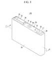
- FIG. 1 illustrates a perspective view of a rechargeable battery according to a first exemplary embodiment
- FIG. 2 illustrates a cross-sectional view of FIG. 1 taken along the line II-II.
- the rechargeable battery 101 may include an electrode assembly 10 (formed by winding a positive electrode (a first electrode) 11 and a negative electrode (a second electrode) 12 with a separator 13 therebetween), a case 26 accommodating the electrode assembly 10, and a cap assembly 30 combined to or coupled with the case 26 at an opening in the case 26.
- an electrode assembly 10 formed by winding a positive electrode (a first electrode) 11 and a negative electrode (a second electrode) 12 with a separator 13 therebetween
- a case 26 accommodating the electrode assembly 10
- a cap assembly 30 combined to or coupled with the case 26 at an opening in the case 26.
- the rechargeable battery 101 according to the present exemplary embodiment is exemplarily illustrated as a prismatic-shaped lithium ion rechargeable battery.
- the embodiments are not limited thereto, and it may be applied to various types of batteries such as a lithium polymer battery, a cylindrical battery, or the like.
- the positive electrode 11 and the negative electrode 12 may include coated regions (where an active material is coated on a current collector formed of a thin metal foil), and uncoated regions 11a and 12a (where the active material is not coated thereon).
- the positive electrode uncoated region 11a may be at one lateral end of the positive electrode 11 along a lengthwise direction thereof, and the negative electrode uncoated region 12a may be at another lateral end of the negative electrode 12 along a lengthwise direction thereof.
- the positive electrode 11 and the negative electrode 12 may be wound while interposing the separator 13, which functions as an insulator, between them.
- the electrode assembly 10 may be formed in a layered structure in which the negative electrode 12 and the positive electrode 11, respectively formed of a plurality of sheets, are layered while interposing the separator 13 between them.
- a plurality of electrode assemblies 10 may be provided in the case 26, and, e.g., the number of electrode assemblies 10 disposed therein may a multiple of 2.
- the case 26 may have a cuboid shape, and one side thereof may have an opening.
- the case 26 may be formed of, e.g., a metal such as aluminum, stainless steel, or the like.
- the cap assembly 30 may include a cap plate 31 (that covers the opening of the case 26), a first terminal 21 (that protrudes out of the cap plate 31 to be electrically connected to the positive electrode 11), and a second terminal 22 (that protrudes out of the cap plate 31 to be electrically connected to the negative electrode 12).
- the cap plate 31 may have an elongated plate shape that is oblong in one direction and is coupleable with the opening of the case 26.
- the cap plate 31 may include a sealing cap 38 that is inserted in an electrolyte injection opening 32, and a vent plate 39 that is provided in a vent hole 34 to be opened at a predetermined pressure and that includes a notch 39a.
- the first and second terminals 21 and 22 may protrude above the cap plate 31.
- the first terminal 21 may be electrically connected to the positive electrode 11 through a first current collecting member 41, and the second terminal 22 may be electrically connected to the negative electrode 12 through a second current collecting member 42.
- the first terminal 21 may be electrically connected to the negative electrode, and the second terminal 22 may be electrically connected to the positive electrode.
- the first terminal 21 may have a rectangular plate shape.
- the first terminal 21 may be electrically connected to the positive electrode 11 through a connecting terminal 25 that is bonded to the first current collecting member 41.
- the connecting terminals 25 that are respectively combined to or coupled with the first and second terminals 21 and 22 may have the same structure.
- a sealing gasket 59 for sealing may be provided between the first terminal 21 and the cap plate 31 to be inserted into a hole through which the connecting terminal 25 penetrates, and a lower insulating member 43 may be provided under the cap plate 31 to support the first current collecting member 41.
- connection member 58 may be provided under the first terminal 21 to electrically connect the first terminal 21 with the cap plate 31.
- the cap plate 31 and the case 26 may be positively charged.
- a resistive layer 57 may be coated on a surface of the connection member 58.
- the resistive layer 57 may be formed of a synthetic resin, e.g., polytetrafluoroethylene (Teflon) or the like.
- resistance between the connection member 58 and the cap plate 31 may increase when a short-circuit current flows.
- a voltage applied to the first current collecting member 41 which is connected in series with the connection member 58, may decrease, and an excessive increase in temperature of the first current collecting member 41 may be reduced and/or prevented.
- the second terminal 22 may have a rectangular plate shape.
- the second terminal 22 may be electrically connected to the negative electrode 12 through the connecting terminal 25 that is bonded to or coupled with the second current collecting member 42.
- the connecting terminal 25 may penetrate through the cap plate 31 and the second terminal 22 such that its upper portion is fixed to or coupled with the second terminal 22.
- a sealing gasket 55 for sealing may be provided between the second terminal 22 and the cap plate 31 to be inserted into a hole through which the connecting terminal 25 penetrates, and a lower insulating member 45 may be provided under the cap plate 31 to insulate the second terminal 22 from the second current collecting member 42.
- a short-circuit protrusion may be formed at a bottom of the second terminal 22 and may protrude toward a short-circuit hole 37.
- the second terminal 22 may be elongated in one direction so as to cover the short-circuit hole 37.
- An upper insulating member 54 may be between the second terminal 22 and the cap plate 31, e.g., for insulation.
- the cap assembly 30 may include a short-circuit member 56 (for short-circuiting the positive electrode 11 with the negative electrode 12), the short-circuit member 56 may be electrically connected to the cap plate 31, and may be deformed to be connected to the second terminal 22 when the internal pressure of the rechargeable battery 101 increases.
- the short-circuit hole 37 may be formed in the cap plate 31, and the short-circuit member 56 may be between the upper insulating member 54 and the cap plate 31 at the short-circuit hole 37.
- the short-circuit member 56 may include a curved portion that is downwardly convex in an arc shape, and an edge portion that is formed at end portions of the curved portion to be fixed to the cap plate 31.
- the internal pressure of the rechargeable battery 101 may increase.
- the curved portion is deformed to be upwardly convex, and in this case, the short-circuit protrusion and the short-circuit member 56 contact each other to cause a short-circuit.
- FIG. 3 illustrates an exploded perspective view of electrode assemblies and a current collecting member according to the first exemplary embodiment
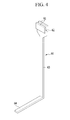
- FIG. 4 illustrates a perspective view of a current distribution member according to the first exemplary embodiment.
- the first current collecting member 41 may include a terminal bonding portion 41a (that is bonded to the connecting terminal 25), a first current collecting member side plate 41c (that is bent toward a bottom of the case 26 from the terminal bonding portion 41a), and an electrode bonding portion 41b (that is elongated toward the bottom of the case 26 and extends from the first current collecting member side plate 41c).
- the terminal bonding portion 41a may have a quadrangular plate shape, and may be fixed to the bottom of the connecting terminal 25 by, e.g., welding.
- the terminal bonding portion 41a may include a coupling hole 41d, and the connecting terminal 25 and the terminal bonding portion 41a may be welded to each other after the protrusion of the connecting terminal 25 is fitted into the coupling hole 41d.
- the first current collecting member side plate 41c may be bent at one end portion of the terminal bonding portion 41a, and may be parallel with lateral sides of the case 26.
- the first current collecting member 41 may include, e.g., two electrode bonding portions 41b, and the electrode bonding portions 41b may be bonded to or coupled with the positive electrode uncoated region 11a and may be bent from the first current collecting member side plate 41c to be parallel with the positive electrode uncoated region 11 a.
- the electrode bonding portions 41b may be respectively bonded to or coupled with the positive electrode uncoated regions 11a of the different electrode assemblies 10 by, e.g., welding.
- the terminal bonding portion 41a may include a fuse hole 41e, and lateral ends of the fuse hole 41e may include a fuse portion 41f having a smaller cross-sectional area than other adjacent portions thereof.
- the fuse portion 41f may be melted earlier than the adjacent portions when an overcurrent flows due to, e.g., a short-circuit, thereby cutting off the current.
- the fuse portion 41f may include a heat conductive member 46, and the heat conductive member 46 may be formed of a polymer having superior heat conductivity and high heat resistance.
- the heat conductive member may have high heat conductivity and may not be susceptible to adverse effects of large amounts of heat.
- the heat conductive member 46 may be formed of a polyimide (PI), and the heat conductive member 46 may be formed by coating such that it may enclose the fuse portion 41f and the adjacent portions of the fuse portion 41f.
- PI polyimide
- the second current collecting member 42 may include a terminal bonding portion 42a that is bonded to or coupled with the connecting terminal 25, a second current collecting member side plate 42c that is bent toward the bottom of the case 26 from the terminal bonding portion 42a, and an electrode bonding portion 42b that is elongated toward the bottom of the case 26 and extends from the second current collecting member side plate 42c.
- the terminal bonding portion 42a has a quadrangular plate shape, and may be fixed to the bottom of the connecting terminal 25 by, e.g., welding.
- the terminal bonding portion 42a may include a coupling hole 42d, and the connecting terminal 25 and the terminal bonding portion 42a may be welded to each other after the protrusion of the connecting terminal 25 is fitted into the coupling hole 42d.
- the second current collecting member side plate 42c may be bent at one end portion of the terminal bonding portion 42a, and may be parallel with lateral sides of the case 26.
- the second current collecting member 42 may include, e.g., two electrode bonding portions 42b, and the electrode bonding portions 42b may be bonded to or coupled with the negative electrode uncoated region 12a while being bent from the second current collecting member side plate 42c to be parallel with the negative electrode uncoated region 12a.
- the electrode bonding portions 42b may be respectively bonded to or coupled with the negative electrode uncoated regions 12a of the different electrode assemblies 10 by, e.g., welding.
- the first current collecting member 41 may be fixed to a current distribution member 60 that electrically connects the case 26 with the first current collecting member 41.
- the current distribution member 60 may include current collecting member-fixing portions 61 that are spaced apart from one another, a connecting portion 63 that downwardly extends toward the bottom of the case 26 from the current collecting member-fixing portions 61, and a case fixing portion 64 that is bent from the connecting portion 63 to be fixed to the bottom of the case 26.
- Each current collecting member-fixing portion 61 may have a plate shape, and may include a supporting groove 62 between the current collecting member-fixing portions 61.
- a lower end of the first current collecting member side plate 41c of the first current collecting member 41 may be inserted into the supporting groove 62, and the current collecting member-fixing portion 61 may be bonded to or coupled with the side plate 41c by, e.g., welding.
- the current distribution member 60 may be fixed to the first current collecting member 41 in an electrical connection path between the fuse portion 41f and the electrode assembly 10.
- the fuse portion 41f may be closer to the first terminal 21 than a bonded or fixed portion of the current distribution member 60 and the first current collecting member 41.
- the first current collecting member side plate 41c may be the portion where the current distribution member 60 and the first current collecting member 41 are bonded or fixed.
- the fuse portion 41f may be between the portion where the first terminal 21, the current distribution member 60, and the first current collecting member 41 are bonded.
- the connecting portion 63 may have a bar shape, and may electrically connect the current collecting member-fixing portion 61 with the case fixing portion 64.
- the case fixing portion 64 may be bent at the connecting portion 63, and may then be parallel with the bottom of the case 26 so as to be bonded thereto by, e.g., welding.
- the current may flow from the positive electrode 11 to the case by way of the first current collecting member 41 and the current distribution member 60.
- the current may flow to the case through, e.g., two different paths.
- the two paths may include, e.g., a first path from the first current collecting member 41 to the case 26 by way of the connecting terminal 25, the first terminal 21, and the cap plate 31, and a second path from the first current collecting member 41 to the case 26 by way of the current distribution member 60.
- first and second resistances may be equal to or only slightly different from each other.
- the resistances for the two paths may be equal to or similar to each other.
- the current may only flow through the path having a lower resistance, and may not flow through the other path, and the current may not be properly distributed.
- a resistance difference may be in a predetermined range.
- the resistance of one path may increase due to, e.g., a temperature increase as a result of a current flow, such that the resistances of the both paths may be equal to each other, thereby distributing the current through both paths.
- the resistance difference may be variously set according to an amount of the short-circuit current and resistivity of the current collecting member.
- the resistance of the second path may be controlled by, e.g., varying a thickness and/or a length of the current distribution member 60.
- the rechargeable battery 101 may further include a safety member on an external surface of the electrode assemblies 10, and the safety member may include a first safety member 71 at one exterior side of the stacked electrode assemblies 10, and a second safety member 72 at another exterior side of the electrode assemblies 10.
- the first safety member 71 may be between one front or wide side surface of the case 26 and the electrode assembly 10
- the second safety member 72 may be between another front or wide side surface of the case 26 and the electrode assembly 10.
- the first safety member 71 may contact an external surface of the electrode assembly 10.
- the first safety member 71 may include a first safety member side plate 71a facing a flat, e.g., side, surface of the electrode assembly 10 that is directed toward or that faces the case, and a fixing tab 71c that protrudes from the first safety member side plate 71a and that is attached to the electrode bonding portion 42b.
- the flat surface may refer to a smooth external circumferential surface of the electrode assembly 10, other than upper and lower curved portions thereof.
- the first safety member side plate 71a and the fixing tab 71c may be formed of, e.g., a conductive metal plate such as copper, stainless steel, or the like.
- An insulating film 71b may be attached to a surface of the first safety member side plate 71a that faces the electrode assembly 10.
- the insulating film 71b may be formed of a polymer material, and may help prevent the first safety member side plate 71a from directly contacting the first electrode assembly 10.
- the second safety member 72 may face the first safety member 71 with the electrode assemblies 10 therebetween.
- the second safety member 72 may face the flat surface of the electrode assembly 10 that faces the case 26.
- the second safety member 72 may include a second safety member side plate 72a attached to or facing the flat surface of the electrode assembly that faces outwardly from the electrode assembly 10, and a fixing tab 72c that protrudes from the second safety member side plate 72a and that is coupled with the electrode bonding portion 42b.
- the second safety member side plate 72a and the fixing tab 72c may be formed of, e.g., a conductive metal plate such as copper, stainless steel, or the like.
- An insulating film 72b may be attached to a surface of the second safety member side plate 72a that faces the electrode assembly 10.
- the insulating film 72b may be formed of a polymer material, and may help prevent the second safety member side plate 72a from directly contacting the first electrode assembly 10.
- the first and second safety members 71 and 72 may be negatively charged and, as shown in FIG. 5 , when a conductive foreign object 75 penetrates therethrough, the first safety member 71 or second safety member 72 may be electrically connected to the case 26 through the conductive foreign object 75.
- the charged current in the electrode assembly 10 may flow to the case 26, and the current may flow from the first current collecting member 41 to the case via the first terminal 21 or via the current distribution member 60.
- the fuse portion 41f may be melted by overheating, e.g., due to overcurrent during the short circuit. Thus, when the conductive foreign object 75 penetrates, the current may not flow through the first current collecting member 41.
- connection member 58 When the connection member 58 is coated with the resistive layer 57 so as to help prevent the excessive amount of heat from being generated in the fuse portion 41f, the heat generated from the fuse portion may be decreased.
- the fuse portion 41f when the current is distributed to the current distribution member 60, the fuse portion 41f may be sustained until the short-circuit current is completely discharged, in addition to helping to prevent the large amount of heat from being generated in the electrode assembly 10 by dissipating it through the fuse portion 41f and the current distribution member 60.
- FIG. 6A illustrates a drawing showing temperature distribution of the current collecting member according to a Comparative Example 1
- FIG. 6B illustrates a drawing showing temperature distribution of the current collecting member according to a Comparative Example 2
- FIG. 6C illustrates a drawing showing temperature distribution of the current collecting member according to the first exemplary embodiment.
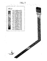
- FIG. 7 illustrates a drawing showing temperature distribution of the current distribution member according to the first exemplary embodiment.
- the rechargeable battery of Comparative Example 1 (in which the connecting member was not formed with the resistive layer and was not provided with the current distribution member) and the rechargeable battery of Comparative Example 2 (in which the connection member was formed with the resistive member but was not provided with the current distribution member) were tested.
- connection member including the resistive layer and the current distribution member.
- the current collecting member of the rechargeable battery of Comparative Example 1 had a 700 °C portion that was higher than a melting point of aluminum (650 °C), and it may be seen that the current collecting member of the rechargeable battery of Comparative Example 2 had a maximum temperature of 50 °C.
- the current collecting member of the rechargeable battery according to the present exemplary embodiment had a maximum temperature of 130 °C.
- the current collecting member of the present exemplary embodiment had a lower temperature than Comparative Example 1 and a higher temperature than Comparative Example 2.
- the temperature of the current distribution member 60 was maintained lower than the melting point of aluminum.
- a voltage applied to the electrode assembly 10 may decrease with the same amount of current, thereby decreasing the amount of heat generated in the electrode assembly 10.
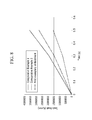
- FIG. 8 illustrates a graph showing joule heat generated outside of the electrode assembly according to passage of time
- FIG. 9 illustrates a graph showing temperature distribution of rechargeable battery parts.
- the heat was distributed to the current collecting member 41 and the current distribution member 60, and the heat was stably discharged while temperatures of the parts were maintained below respective melting points.
- FIG. 10 illustrates a partial cross-sectional view of a rechargeable battery according to a second exemplary embodiment
- FIG. 11 illustrates a perspective view of a current distribution member according to the second exemplary embodiment.
- a rechargeable battery 102 according to the present exemplary embodiment may have the same general structure as the rechargeable battery according to the aforementioned first exemplary embodiment, except for a current distribution member 80, so a repeated description of the same structure may be omitted.
- a current distribution member 80 may be fixedly provided on, e.g., fixed to, the first current collecting member 41 to electrically connect the case 26 and the first current collecting member 41.
- the current distribution member 80 may include current collecting member-fixing portions 81 that are spaced apart from one another, a connecting portion 83 that downwardly extends toward the bottom of the case 26 from the current collecting member-fixing portions 81, an inclined portion 85' that is slantedly bent, e.g., bent at an inclined angle, from the connecting portion 83, and a case fixing portion 84 that is bent at the connecting portion 83 to be fixed to the bottom of the case 26.
- Each current collecting member-fixing portion 81 may have a plate shape, the current distribution member 80 may have two current collecting member-fixing portions 81 that are spaced apart from each other, and the current collecting member-fixing portions 81 may include a supporting groove 82 therebetween.
- a lower end of the first current collecting member side plate 41c of the first current collecting member 41 may be inserted in the supporting groove 82, and the current collecting member-fixing portion 81 may be bonded to or coupled with the first current collecting member side plate 41c by, e.g., welding.
- the connecting portion 83 may have a bar shape, and may extend in a heightwise direction of the case 26.
- the inclined portion 85 may be formed such that it is slantedly bent, with respect to a lengthwise direction of the connecting portion 83, from the connecting portion 83 toward a lateral side of the case 26.
- the lateral side of the case may refer to a side thereof that extends from the bottom of the case 26 and faces a lateral side end portion of the electrode assembly 10.
- the case fixing portion 84 may be bent, e.g., slantedly bent, from the inclined portion 85, and may be bonded to a lateral side lower end of the case 26 by, e.g., welding, while being while being parallel with the lateral side of the case 26.
- FIG. 12 illustrates a partial cross-sectional view of a rechargeable battery according to a third exemplary embodiment of
- FIG. 13 illustrates a perspective view of a current distribution member according to the third exemplary embodiment.
- the rechargeable battery 103 according to the present exemplary embodiment may have the same general structure as the rechargeable battery according to the aforementioned first exemplary embodiment, except for a current distribution member 90, so a repeated description of the same structure may be omitted.
- the first current collecting member 41 may be fixedly provided with, e.g., fixed to, a current distribution member 90 that electrically connects the case 26 with the first current collecting member 41.
- the current distribution member 90 may include current collecting member-fixing portions 91 that are spaced apart from one another, a connecting portion 93 that downwardly extends toward the bottom of the case 26 from the current collecting member-fixing portions 91, and a case fixing portion 94 that is bent from the connecting portion 93 an fixed to the bottom of the case 26.
- Each current collecting member-fixing portion 91 may have a plate shape, and two current collecting member-fixing portions 91 may be spaced apart from one another to face each other.
- the current collecting member-fixing portions 91 may include a supporting groove 92 therebetween, and a lateral side end portion of the electrode assemblies 10 may be inserted in the supporting groove 92.
- the current collecting member-fixing portion 91 may be fixed to the first current collecting member 41 such that it is fixed to the electrode bonding portion 41b of the first current collecting member 41 by, e.g., welding.
- the fuse portion 41f may be closer to the first terminal 21 than a bonded portion of the current distribution member 90 and the first current collecting member 41.
- the electrode bonding portion 41b may refer to the bonded portion of the current distribution member 90 and the first current collecting member 41.
- the connecting portion 93 may have a bar shape, and may extend in a heightwise direction of the case 26.
- the case fixing portion 94 may be bent from the connecting portion 93 and may be bonded to the bottom of the case 26 by, e.g., welding, while being parallel thereto.
- the embodiments may provide a rechargeable battery that can distribute a short-circuit current (and heat associated therewith) if an external short-circuit occurs.
- the current distribution member may be provided to distribute an overcurrent (and heat associated therewith) generated when a short-circuit occurs.
- the battery according to an embodiment may help prevent the electrode assembly from being overheated because heat discharging is induced through the current distribution member.
Landscapes
- Chemical & Material Sciences (AREA)
- Chemical Kinetics & Catalysis (AREA)
- Electrochemistry (AREA)
- General Chemical & Material Sciences (AREA)
- Engineering & Computer Science (AREA)
- Manufacturing & Machinery (AREA)
- Connection Of Batteries Or Terminals (AREA)
Applications Claiming Priority (1)
| Application Number | Priority Date | Filing Date | Title |
|---|---|---|---|
| KR1020140046310A KR102246729B1 (ko) | 2014-04-17 | 2014-04-17 | 전류 분산 부재를 갖는 이차 전지 |
Publications (2)
| Publication Number | Publication Date |
|---|---|
| EP2933856A1 true EP2933856A1 (de) | 2015-10-21 |
| EP2933856B1 EP2933856B1 (de) | 2019-08-07 |
Family
ID=52736829
Family Applications (1)
| Application Number | Title | Priority Date | Filing Date |
|---|---|---|---|
| EP15158336.6A Active EP2933856B1 (de) | 2014-04-17 | 2015-03-10 | Wiederaufladbare batterie mit stromverteilungselement |
Country Status (3)
| Country | Link |
|---|---|
| US (1) | US10312496B2 (de) |
| EP (1) | EP2933856B1 (de) |
| KR (1) | KR102246729B1 (de) |
Cited By (2)
| Publication number | Priority date | Publication date | Assignee | Title |
|---|---|---|---|---|
| WO2023031297A1 (de) * | 2021-09-01 | 2023-03-09 | Volkswagen Aktiengesellschaft | Batteriezelle, batterieanordnung und verfahren zur herstellung einer batteriezelle |
| EP4037091A4 (de) * | 2019-09-26 | 2023-10-04 | SANYO Electric Co., Ltd. | Sekundärbatterie |
Families Citing this family (9)
| Publication number | Priority date | Publication date | Assignee | Title |
|---|---|---|---|---|
| EP3544090B1 (de) * | 2016-12-02 | 2020-12-16 | Contemporary Amperex Technology Co., Limited | Abdeckplattenanordnung für hochleistungsbatterie und hochleistungsbatterie damit |
| CN109285974B (zh) * | 2017-07-20 | 2021-08-03 | 宁德时代新能源科技股份有限公司 | 二次电池顶盖组件及二次电池 |
| US11527800B2 (en) * | 2017-12-13 | 2022-12-13 | Samsung Sdi Co., Ltd. | Secondary battery |
| CN108258180B (zh) * | 2018-01-16 | 2020-09-29 | 宁德时代新能源科技股份有限公司 | 集流构件和电池 |
| KR102663724B1 (ko) * | 2018-09-19 | 2024-05-07 | 삼성에스디아이 주식회사 | 이차 전지 |
| KR102871159B1 (ko) * | 2019-07-08 | 2025-10-16 | 삼성에스디아이 주식회사 | 이차 전지 |
| WO2021124796A1 (ja) * | 2019-12-19 | 2021-06-24 | パナソニック株式会社 | 非水電解質二次電池 |
| KR20230115756A (ko) * | 2022-01-27 | 2023-08-03 | 삼성에스디아이 주식회사 | 이차전지 |
| KR20250076849A (ko) * | 2023-11-23 | 2025-05-30 | 삼성에스디아이 주식회사 | 이차전지 |
Citations (3)
| Publication number | Priority date | Publication date | Assignee | Title |
|---|---|---|---|---|
| EP2515363A1 (de) * | 2011-04-18 | 2012-10-24 | SB LiMotive Co., Ltd. | Sekundärbatterie |
| EP2575189A1 (de) * | 2011-09-29 | 2013-04-03 | Samsung SDI Co., Ltd. | Wiederaufladbare Batterie |
| US20130288115A1 (en) * | 2012-04-26 | 2013-10-31 | Medtronic, Inc. | Mandrel for electrode assemblies |
Family Cites Families (9)
| Publication number | Priority date | Publication date | Assignee | Title |
|---|---|---|---|---|
| US6499823B2 (en) * | 2000-06-15 | 2002-12-31 | Canon Kabushiki Kaisha | Ink jet recording head having substrate and ceiling plate base pressed together by base plate and ink supply member |
| JP2002313295A (ja) * | 2001-04-11 | 2002-10-25 | Gs-Melcotec Co Ltd | 二次電池パック |
| JP4572056B2 (ja) * | 2002-10-04 | 2010-10-27 | 信越化学工業株式会社 | 熱伝導性シリコーンゴム複合シート |
| KR100502337B1 (ko) * | 2002-12-26 | 2005-07-20 | 삼성에스디아이 주식회사 | 리튬 이차 전지 |
| US9099732B2 (en) * | 2010-06-11 | 2015-08-04 | Samsung Sdi Co., Ltd. | Rechargeable battery having a fuse with an insulating blocking member |
| US8722237B2 (en) * | 2011-03-29 | 2014-05-13 | Samsung Sdi Co., Ltd. | Secondary battery |
| KR20130053026A (ko) | 2011-11-14 | 2013-05-23 | 삼성에스디아이 주식회사 | 이차전지 |
| KR20150032086A (ko) * | 2013-09-17 | 2015-03-25 | 삼성에스디아이 주식회사 | 안전부재를 갖는 이차 전지 |
| CN203644834U (zh) * | 2013-11-11 | 2014-06-11 | 宁德新能源科技有限公司 | 一种动力电池安全顶盖 |
-
2014
- 2014-04-17 KR KR1020140046310A patent/KR102246729B1/ko active Active
- 2014-12-09 US US14/564,712 patent/US10312496B2/en active Active
-
2015
- 2015-03-10 EP EP15158336.6A patent/EP2933856B1/de active Active
Patent Citations (3)
| Publication number | Priority date | Publication date | Assignee | Title |
|---|---|---|---|---|
| EP2515363A1 (de) * | 2011-04-18 | 2012-10-24 | SB LiMotive Co., Ltd. | Sekundärbatterie |
| EP2575189A1 (de) * | 2011-09-29 | 2013-04-03 | Samsung SDI Co., Ltd. | Wiederaufladbare Batterie |
| US20130288115A1 (en) * | 2012-04-26 | 2013-10-31 | Medtronic, Inc. | Mandrel for electrode assemblies |
Cited By (3)
| Publication number | Priority date | Publication date | Assignee | Title |
|---|---|---|---|---|
| EP4037091A4 (de) * | 2019-09-26 | 2023-10-04 | SANYO Electric Co., Ltd. | Sekundärbatterie |
| US12142796B2 (en) | 2019-09-26 | 2024-11-12 | Sanyo Electric Co., Ltd. | Secondary battery |
| WO2023031297A1 (de) * | 2021-09-01 | 2023-03-09 | Volkswagen Aktiengesellschaft | Batteriezelle, batterieanordnung und verfahren zur herstellung einer batteriezelle |
Also Published As
| Publication number | Publication date |
|---|---|
| US20150303439A1 (en) | 2015-10-22 |
| EP2933856B1 (de) | 2019-08-07 |
| US10312496B2 (en) | 2019-06-04 |
| KR20150120261A (ko) | 2015-10-27 |
| KR102246729B1 (ko) | 2021-04-29 |
Similar Documents
| Publication | Publication Date | Title |
|---|---|---|
| EP2933856B1 (de) | Wiederaufladbare batterie mit stromverteilungselement | |
| CN109473572B (zh) | 具有利用排出气体断开连接器的结构的电池模块 | |
| EP2793291B1 (de) | Wiederaufladbares batteriemodul | |
| EP2575189B1 (de) | Wiederaufladbare Batterie | |
| US10044019B2 (en) | Battery module having short-circuit connection member | |
| KR102253021B1 (ko) | 퓨즈부를 갖는 이차 전지 및 전지 모듈 | |
| CN109428043B (zh) | 二次电池 | |
| EP2793295A2 (de) | Wiederaufladbare Batterie | |
| CN117996359A (zh) | 可再充电电池 | |
| JP2017076601A (ja) | バッテリーセル | |
| US10236494B2 (en) | Secondary battery | |
| CN104112836A (zh) | 可再充电电池 | |
| KR20160019016A (ko) | 퓨즈를 갖는 이차 전지 | |
| KR102189549B1 (ko) | 퓨즈부를 갖는 이차 전지 | |
| CN109937495B (zh) | 可再充电电池 | |
| JP6936397B2 (ja) | 接続構造および電池モジュール | |
| CN105938891B (zh) | 具有连接构件的可再充电电池 | |
| KR20200054757A (ko) | 과충전 방지가 가능한 구조를 갖는 배터리 팩 및 이를 포함하는 자동차 | |
| KR20200054756A (ko) | 과충전 방지가 가능한 구조를 갖는 배터리 팩 충전 시스템 및 이를 포함하는 자동차 | |
| US20230402723A1 (en) | Battery pack | |
| US9997762B2 (en) | Protection element and rechargeable battery including the same | |
| KR20200053375A (ko) | 과충전 방지가 가능한 구조를 갖는 배터리 셀, 이를 포함하는 배터리 팩, 그리고 이러한 배터리 팩을 포함하는 자동차 | |
| US9166256B2 (en) | Rechargeable battery | |
| KR20070081301A (ko) | 전지캡에 장착 가능한 보호 소자 및 이를 구비한 이차 전지 | |
| US20150303433A1 (en) | Rechargeable battery module |
Legal Events
| Date | Code | Title | Description |
|---|---|---|---|
| PUAI | Public reference made under article 153(3) epc to a published international application that has entered the european phase |
Free format text: ORIGINAL CODE: 0009012 |
|
| AK | Designated contracting states |
Kind code of ref document: A1 Designated state(s): AL AT BE BG CH CY CZ DE DK EE ES FI FR GB GR HR HU IE IS IT LI LT LU LV MC MK MT NL NO PL PT RO RS SE SI SK SM TR |
|
| AX | Request for extension of the european patent |
Extension state: BA ME |
|
| 17P | Request for examination filed |
Effective date: 20160419 |
|
| RBV | Designated contracting states (corrected) |
Designated state(s): AL AT BE BG CH CY CZ DE DK EE ES FI FR GB GR HR HU IE IS IT LI LT LU LV MC MK MT NL NO PL PT RO RS SE SI SK SM TR |
|
| STAA | Information on the status of an ep patent application or granted ep patent |
Free format text: STATUS: REQUEST FOR EXAMINATION WAS MADE |
|
| R17P | Request for examination filed (corrected) |
Effective date: 20160419 |
|
| STAA | Information on the status of an ep patent application or granted ep patent |
Free format text: STATUS: EXAMINATION IS IN PROGRESS |
|
| 17Q | First examination report despatched |
Effective date: 20170531 |
|
| GRAP | Despatch of communication of intention to grant a patent |
Free format text: ORIGINAL CODE: EPIDOSNIGR1 |
|
| STAA | Information on the status of an ep patent application or granted ep patent |
Free format text: STATUS: GRANT OF PATENT IS INTENDED |
|
| INTG | Intention to grant announced |
Effective date: 20190312 |
|
| GRAS | Grant fee paid |
Free format text: ORIGINAL CODE: EPIDOSNIGR3 |
|
| GRAA | (expected) grant |
Free format text: ORIGINAL CODE: 0009210 |
|
| STAA | Information on the status of an ep patent application or granted ep patent |
Free format text: STATUS: THE PATENT HAS BEEN GRANTED |
|
| AK | Designated contracting states |
Kind code of ref document: B1 Designated state(s): AL AT BE BG CH CY CZ DE DK EE ES FI FR GB GR HR HU IE IS IT LI LT LU LV MC MK MT NL NO PL PT RO RS SE SI SK SM TR |
|
| REG | Reference to a national code |
Ref country code: GB Ref legal event code: FG4D |
|
| REG | Reference to a national code |
Ref country code: CH Ref legal event code: EP Ref country code: AT Ref legal event code: REF Ref document number: 1165194 Country of ref document: AT Kind code of ref document: T Effective date: 20190815 |
|
| REG | Reference to a national code |
Ref country code: DE Ref legal event code: R096 Ref document number: 602015035085 Country of ref document: DE |
|
| REG | Reference to a national code |
Ref country code: IE Ref legal event code: FG4D |
|
| REG | Reference to a national code |
Ref country code: NL Ref legal event code: MP Effective date: 20190807 |
|
| REG | Reference to a national code |
Ref country code: LT Ref legal event code: MG4D |
|
| PG25 | Lapsed in a contracting state [announced via postgrant information from national office to epo] |
Ref country code: FI Free format text: LAPSE BECAUSE OF FAILURE TO SUBMIT A TRANSLATION OF THE DESCRIPTION OR TO PAY THE FEE WITHIN THE PRESCRIBED TIME-LIMIT Effective date: 20190807 Ref country code: HR Free format text: LAPSE BECAUSE OF FAILURE TO SUBMIT A TRANSLATION OF THE DESCRIPTION OR TO PAY THE FEE WITHIN THE PRESCRIBED TIME-LIMIT Effective date: 20190807 Ref country code: SE Free format text: LAPSE BECAUSE OF FAILURE TO SUBMIT A TRANSLATION OF THE DESCRIPTION OR TO PAY THE FEE WITHIN THE PRESCRIBED TIME-LIMIT Effective date: 20190807 Ref country code: NO Free format text: LAPSE BECAUSE OF FAILURE TO SUBMIT A TRANSLATION OF THE DESCRIPTION OR TO PAY THE FEE WITHIN THE PRESCRIBED TIME-LIMIT Effective date: 20191107 Ref country code: PT Free format text: LAPSE BECAUSE OF FAILURE TO SUBMIT A TRANSLATION OF THE DESCRIPTION OR TO PAY THE FEE WITHIN THE PRESCRIBED TIME-LIMIT Effective date: 20191209 Ref country code: LT Free format text: LAPSE BECAUSE OF FAILURE TO SUBMIT A TRANSLATION OF THE DESCRIPTION OR TO PAY THE FEE WITHIN THE PRESCRIBED TIME-LIMIT Effective date: 20190807 Ref country code: NL Free format text: LAPSE BECAUSE OF FAILURE TO SUBMIT A TRANSLATION OF THE DESCRIPTION OR TO PAY THE FEE WITHIN THE PRESCRIBED TIME-LIMIT Effective date: 20190807 Ref country code: BG Free format text: LAPSE BECAUSE OF FAILURE TO SUBMIT A TRANSLATION OF THE DESCRIPTION OR TO PAY THE FEE WITHIN THE PRESCRIBED TIME-LIMIT Effective date: 20191107 |
|
| REG | Reference to a national code |
Ref country code: AT Ref legal event code: MK05 Ref document number: 1165194 Country of ref document: AT Kind code of ref document: T Effective date: 20190807 |
|
| PG25 | Lapsed in a contracting state [announced via postgrant information from national office to epo] |
Ref country code: RS Free format text: LAPSE BECAUSE OF FAILURE TO SUBMIT A TRANSLATION OF THE DESCRIPTION OR TO PAY THE FEE WITHIN THE PRESCRIBED TIME-LIMIT Effective date: 20190807 Ref country code: LV Free format text: LAPSE BECAUSE OF FAILURE TO SUBMIT A TRANSLATION OF THE DESCRIPTION OR TO PAY THE FEE WITHIN THE PRESCRIBED TIME-LIMIT Effective date: 20190807 Ref country code: AL Free format text: LAPSE BECAUSE OF FAILURE TO SUBMIT A TRANSLATION OF THE DESCRIPTION OR TO PAY THE FEE WITHIN THE PRESCRIBED TIME-LIMIT Effective date: 20190807 Ref country code: GR Free format text: LAPSE BECAUSE OF FAILURE TO SUBMIT A TRANSLATION OF THE DESCRIPTION OR TO PAY THE FEE WITHIN THE PRESCRIBED TIME-LIMIT Effective date: 20191108 Ref country code: ES Free format text: LAPSE BECAUSE OF FAILURE TO SUBMIT A TRANSLATION OF THE DESCRIPTION OR TO PAY THE FEE WITHIN THE PRESCRIBED TIME-LIMIT Effective date: 20190807 Ref country code: IS Free format text: LAPSE BECAUSE OF FAILURE TO SUBMIT A TRANSLATION OF THE DESCRIPTION OR TO PAY THE FEE WITHIN THE PRESCRIBED TIME-LIMIT Effective date: 20191207 |
|
| PG25 | Lapsed in a contracting state [announced via postgrant information from national office to epo] |
Ref country code: TR Free format text: LAPSE BECAUSE OF FAILURE TO SUBMIT A TRANSLATION OF THE DESCRIPTION OR TO PAY THE FEE WITHIN THE PRESCRIBED TIME-LIMIT Effective date: 20190807 |
|
| PG25 | Lapsed in a contracting state [announced via postgrant information from national office to epo] |
Ref country code: PL Free format text: LAPSE BECAUSE OF FAILURE TO SUBMIT A TRANSLATION OF THE DESCRIPTION OR TO PAY THE FEE WITHIN THE PRESCRIBED TIME-LIMIT Effective date: 20190807 Ref country code: EE Free format text: LAPSE BECAUSE OF FAILURE TO SUBMIT A TRANSLATION OF THE DESCRIPTION OR TO PAY THE FEE WITHIN THE PRESCRIBED TIME-LIMIT Effective date: 20190807 Ref country code: RO Free format text: LAPSE BECAUSE OF FAILURE TO SUBMIT A TRANSLATION OF THE DESCRIPTION OR TO PAY THE FEE WITHIN THE PRESCRIBED TIME-LIMIT Effective date: 20190807 Ref country code: AT Free format text: LAPSE BECAUSE OF FAILURE TO SUBMIT A TRANSLATION OF THE DESCRIPTION OR TO PAY THE FEE WITHIN THE PRESCRIBED TIME-LIMIT Effective date: 20190807 Ref country code: DK Free format text: LAPSE BECAUSE OF FAILURE TO SUBMIT A TRANSLATION OF THE DESCRIPTION OR TO PAY THE FEE WITHIN THE PRESCRIBED TIME-LIMIT Effective date: 20190807 Ref country code: IT Free format text: LAPSE BECAUSE OF FAILURE TO SUBMIT A TRANSLATION OF THE DESCRIPTION OR TO PAY THE FEE WITHIN THE PRESCRIBED TIME-LIMIT Effective date: 20190807 |
|
| PG25 | Lapsed in a contracting state [announced via postgrant information from national office to epo] |
Ref country code: SK Free format text: LAPSE BECAUSE OF FAILURE TO SUBMIT A TRANSLATION OF THE DESCRIPTION OR TO PAY THE FEE WITHIN THE PRESCRIBED TIME-LIMIT Effective date: 20190807 Ref country code: CZ Free format text: LAPSE BECAUSE OF FAILURE TO SUBMIT A TRANSLATION OF THE DESCRIPTION OR TO PAY THE FEE WITHIN THE PRESCRIBED TIME-LIMIT Effective date: 20190807 Ref country code: SM Free format text: LAPSE BECAUSE OF FAILURE TO SUBMIT A TRANSLATION OF THE DESCRIPTION OR TO PAY THE FEE WITHIN THE PRESCRIBED TIME-LIMIT Effective date: 20190807 Ref country code: IS Free format text: LAPSE BECAUSE OF FAILURE TO SUBMIT A TRANSLATION OF THE DESCRIPTION OR TO PAY THE FEE WITHIN THE PRESCRIBED TIME-LIMIT Effective date: 20200224 |
|
| REG | Reference to a national code |
Ref country code: DE Ref legal event code: R097 Ref document number: 602015035085 Country of ref document: DE |
|
| PLBE | No opposition filed within time limit |
Free format text: ORIGINAL CODE: 0009261 |
|
| STAA | Information on the status of an ep patent application or granted ep patent |
Free format text: STATUS: NO OPPOSITION FILED WITHIN TIME LIMIT |
|
| PG2D | Information on lapse in contracting state deleted |
Ref country code: IS |
|
| 26N | No opposition filed |
Effective date: 20200603 |
|
| PG25 | Lapsed in a contracting state [announced via postgrant information from national office to epo] |
Ref country code: SI Free format text: LAPSE BECAUSE OF FAILURE TO SUBMIT A TRANSLATION OF THE DESCRIPTION OR TO PAY THE FEE WITHIN THE PRESCRIBED TIME-LIMIT Effective date: 20190807 |
|
| PG25 | Lapsed in a contracting state [announced via postgrant information from national office to epo] |
Ref country code: MC Free format text: LAPSE BECAUSE OF FAILURE TO SUBMIT A TRANSLATION OF THE DESCRIPTION OR TO PAY THE FEE WITHIN THE PRESCRIBED TIME-LIMIT Effective date: 20190807 |
|
| REG | Reference to a national code |
Ref country code: CH Ref legal event code: PL |
|
| REG | Reference to a national code |
Ref country code: DE Ref legal event code: R079 Ref document number: 602015035085 Country of ref document: DE Free format text: PREVIOUS MAIN CLASS: H01M0002020000 Ipc: H01M0050100000 |
|
| REG | Reference to a national code |
Ref country code: BE Ref legal event code: MM Effective date: 20200331 |
|
| PG25 | Lapsed in a contracting state [announced via postgrant information from national office to epo] |
Ref country code: LU Free format text: LAPSE BECAUSE OF NON-PAYMENT OF DUE FEES Effective date: 20200310 |
|
| PG25 | Lapsed in a contracting state [announced via postgrant information from national office to epo] |
Ref country code: LI Free format text: LAPSE BECAUSE OF NON-PAYMENT OF DUE FEES Effective date: 20200331 Ref country code: CH Free format text: LAPSE BECAUSE OF NON-PAYMENT OF DUE FEES Effective date: 20200331 Ref country code: IE Free format text: LAPSE BECAUSE OF NON-PAYMENT OF DUE FEES Effective date: 20200310 |
|
| PG25 | Lapsed in a contracting state [announced via postgrant information from national office to epo] |
Ref country code: BE Free format text: LAPSE BECAUSE OF NON-PAYMENT OF DUE FEES Effective date: 20200331 |
|
| PG25 | Lapsed in a contracting state [announced via postgrant information from national office to epo] |
Ref country code: MT Free format text: LAPSE BECAUSE OF FAILURE TO SUBMIT A TRANSLATION OF THE DESCRIPTION OR TO PAY THE FEE WITHIN THE PRESCRIBED TIME-LIMIT Effective date: 20190807 Ref country code: CY Free format text: LAPSE BECAUSE OF FAILURE TO SUBMIT A TRANSLATION OF THE DESCRIPTION OR TO PAY THE FEE WITHIN THE PRESCRIBED TIME-LIMIT Effective date: 20190807 |
|
| PG25 | Lapsed in a contracting state [announced via postgrant information from national office to epo] |
Ref country code: MK Free format text: LAPSE BECAUSE OF FAILURE TO SUBMIT A TRANSLATION OF THE DESCRIPTION OR TO PAY THE FEE WITHIN THE PRESCRIBED TIME-LIMIT Effective date: 20190807 |
|
| P01 | Opt-out of the competence of the unified patent court (upc) registered |
Effective date: 20230528 |
|
| PGFP | Annual fee paid to national office [announced via postgrant information from national office to epo] |
Ref country code: GB Payment date: 20260303 Year of fee payment: 12 |
|
| PGFP | Annual fee paid to national office [announced via postgrant information from national office to epo] |
Ref country code: DE Payment date: 20260305 Year of fee payment: 12 |
|
| PGFP | Annual fee paid to national office [announced via postgrant information from national office to epo] |
Ref country code: FR Payment date: 20260309 Year of fee payment: 12 |