EP2933495B1 - Fan attachment - Google Patents
Fan attachment Download PDFInfo
- Publication number
- EP2933495B1 EP2933495B1 EP15163007.6A EP15163007A EP2933495B1 EP 2933495 B1 EP2933495 B1 EP 2933495B1 EP 15163007 A EP15163007 A EP 15163007A EP 2933495 B1 EP2933495 B1 EP 2933495B1
- Authority
- EP
- European Patent Office
- Prior art keywords
- fastening
- geometry
- holding device
- holding
- guide
- Prior art date
- Legal status (The legal status is an assumption and is not a legal conclusion. Google has not performed a legal analysis and makes no representation as to the accuracy of the status listed.)
- Active
Links
Images


Classifications
-
- F—MECHANICAL ENGINEERING; LIGHTING; HEATING; WEAPONS; BLASTING
- F04—POSITIVE - DISPLACEMENT MACHINES FOR LIQUIDS; PUMPS FOR LIQUIDS OR ELASTIC FLUIDS
- F04D—NON-POSITIVE-DISPLACEMENT PUMPS
- F04D19/00—Axial-flow pumps
- F04D19/002—Axial flow fans
-
- F—MECHANICAL ENGINEERING; LIGHTING; HEATING; WEAPONS; BLASTING
- F04—POSITIVE - DISPLACEMENT MACHINES FOR LIQUIDS; PUMPS FOR LIQUIDS OR ELASTIC FLUIDS
- F04D—NON-POSITIVE-DISPLACEMENT PUMPS
- F04D25/00—Pumping installations or systems
- F04D25/02—Units comprising pumps and their driving means
- F04D25/08—Units comprising pumps and their driving means the working fluid being air, e.g. for ventilation
-
- F—MECHANICAL ENGINEERING; LIGHTING; HEATING; WEAPONS; BLASTING
- F04—POSITIVE - DISPLACEMENT MACHINES FOR LIQUIDS; PUMPS FOR LIQUIDS OR ELASTIC FLUIDS
- F04D—NON-POSITIVE-DISPLACEMENT PUMPS
- F04D29/00—Details, component parts, or accessories
- F04D29/40—Casings; Connections of working fluid
- F04D29/52—Casings; Connections of working fluid for axial pumps
- F04D29/522—Casings; Connections of working fluid for axial pumps especially adapted for elastic fluid pumps
-
- F—MECHANICAL ENGINEERING; LIGHTING; HEATING; WEAPONS; BLASTING
- F04—POSITIVE - DISPLACEMENT MACHINES FOR LIQUIDS; PUMPS FOR LIQUIDS OR ELASTIC FLUIDS
- F04D—NON-POSITIVE-DISPLACEMENT PUMPS
- F04D29/00—Details, component parts, or accessories
- F04D29/60—Mounting; Assembling; Disassembling
- F04D29/601—Mounting; Assembling; Disassembling specially adapted for elastic fluid pumps
-
- F—MECHANICAL ENGINEERING; LIGHTING; HEATING; WEAPONS; BLASTING
- F05—INDEXING SCHEMES RELATING TO ENGINES OR PUMPS IN VARIOUS SUBCLASSES OF CLASSES F01-F04
- F05D—INDEXING SCHEME FOR ASPECTS RELATING TO NON-POSITIVE-DISPLACEMENT MACHINES OR ENGINES, GAS-TURBINES OR JET-PROPULSION PLANTS
- F05D2230/00—Manufacture
- F05D2230/60—Assembly methods
- F05D2230/61—Assembly methods using limited numbers of standard modules which can be adapted by machining
-
- F—MECHANICAL ENGINEERING; LIGHTING; HEATING; WEAPONS; BLASTING
- F05—INDEXING SCHEMES RELATING TO ENGINES OR PUMPS IN VARIOUS SUBCLASSES OF CLASSES F01-F04
- F05D—INDEXING SCHEME FOR ASPECTS RELATING TO NON-POSITIVE-DISPLACEMENT MACHINES OR ENGINES, GAS-TURBINES OR JET-PROPULSION PLANTS
- F05D2260/00—Function
- F05D2260/30—Retaining components in desired mutual position
- F05D2260/33—Retaining components in desired mutual position with a bayonet coupling
-
- F—MECHANICAL ENGINEERING; LIGHTING; HEATING; WEAPONS; BLASTING
- F05—INDEXING SCHEMES RELATING TO ENGINES OR PUMPS IN VARIOUS SUBCLASSES OF CLASSES F01-F04
- F05D—INDEXING SCHEME FOR ASPECTS RELATING TO NON-POSITIVE-DISPLACEMENT MACHINES OR ENGINES, GAS-TURBINES OR JET-PROPULSION PLANTS
- F05D2260/00—Function
- F05D2260/30—Retaining components in desired mutual position
- F05D2260/36—Retaining components in desired mutual position by a form fit connection, e.g. by interlocking
Definitions
- the invention relates to a fastening device for a fan, in particular a wall ring axial fan.
- a common application of fans is the use as a cooling device on waste heat-producing devices.
- waste heat-producing devices can, for example, be heat exchangers, the fan being attached directly to the heat exchanger or to a housing accommodating the heat exchanger.
- Fans for such applications can have a wall ring over which the attachment is made. For this purpose, holes and partially threaded inserts are provided on the end face of the wall ring. This type of attachment is widely used, for example, in the finned heat exchangers that have mostly been used to date.
- German laid-open publication discloses DE 10 2012 109 516 A1 a carrier element for holding a fan, in particular an axial fan, with a wall ring for receiving the fan.
- the wall ring On its outer circumference, the wall ring has a hinge which consists of a first hinge part connected to the wall ring and a second hinge part which can be pivoted relative to the first hinge part about a hinge axis.
- German patent specification DE 10 2010 045 899 B3 discloses a fan unit with a fixed support ring and an electrical axial fan arranged in the support ring, the support ring being fastened in a mounting housing by means of suspension members.
- the support ring have a plurality of circumferentially distributed holding pins which are each designed to attach a suspension member made of an elastomeric material, and the suspension members have corresponding plug-in openings for attaching to the retaining pins.
- the United States patent application US 2014/0056693 A discloses a fan with a fan frame and a fan wheel.
- the fan frame has a frame body and at least two vibration-resistant elements.
- the frame body has at least two positioning ribs, the at least two positioning ribs protruding from a side wall of the frame body and being distributed symmetrically.
- Each of the vibration-proof elements has a positioning groove.
- the positioning rib of the frame body is capable of engaging in the positioning groove of the vibration-proof member to position the vibration-proof member on the side wall of the frame body.
- the fan wheel is rotatably arranged in the fan frame.
- the United States patent application US 2010/0111698 A discloses an airflow device having a stator section, at least one stator blade, and a plurality of mounting flanges on the stator section.
- the air flow device has at least one slot between a plurality of mounting flanges, a rotor arrangement to which at least one stator blade is coupled, the rotor arrangement having a proximal end and a distal end.
- the airflow device comprises at least one fan blade, which is coupled to the rotor arrangement.
- the airflow device further comprises a locking device, the locking device having at least one fastening element and at least one coupling element, the at least one slot being coupled to the at least one coupling element.
- the object of the invention is therefore to provide a fastening device of a wall ring axial fan, which can be used in applications in which the fan is to be fastened to a design other than a lamella heat exchanger while maintaining the wall ring.
- this fastening option should be optionally possible, so that the conventional fastening of the wall ring axial fan is still possible without restriction.
- a fastening system for fastening a wall ring axial fan to a device.
- the fastening system is provided with a wall ring as a fastening device, a fan and a holding means, the fastening device being provided in the radial direction around the fan and the fan being connected to the fastening device via the holding means.
- the fastening device has a first fastening geometry.
- the fastening system comprises the fastening device and additionally has a holding device, the fastening device having at least one further, second fastening geometry for fastening the holding device to the fastening device.
- the fastening device and thus the wall ring axial fan can be fastened to a device in a conventional manner via the first fastening geometry.
- the first fastening geometry consists of bores in a flange of the fastening device, so that the wall ring axial fan can be installed in an annular opening such as the wall of a heat exchanger or a heat exchanger housing and can be fastened by means of a fastening means, for example a screw.
- the second fastening geometry is used to fasten the holding device to the fastening device, so that the wall ring axial fan, via the holding device, is designed on a construction of a device other than a lamella heat exchanger, for example on a base plate of a heat exchanger unit. can be attached.
- One and the same wall ring axial fan can be adapted to customer-specific installation situations such as different installation heights or different mounting positions by using different holding devices, without changing the underlying wall ring axial fan itself.
- the second fastening geometry is provided on the circumference of the fastening device.
- the fastening device has a collar on its circumference, the second fastening geometry being provided on the circumference of the collar.
- the second fastening geometry has a first guide into which the holding device can be inserted, the outer diameter of the first guide being at most the same size as the maximum outer diameter of the fastening device. Installation in an annular opening is thus possible without hindrance despite the additional first guide.
- the first guide is designed as a dovetail guide and can have a trapezoidal shape or a cylindrical shape, for example.
- the holding device has at least one second guide which can be operatively connected to the first guide of the second fastening geometry.
- the holding device can be inserted with its second guide into the first guide of the fastening device.
- the guides of the second fastening geometry and the holding device have corresponding bevels in the axial direction.
- the two parts can be easily joined and still sit without play in the end position.
- the bevels can serve as draft angles when the parts are cast.
- the fastening device and the holding device can be made of a plastic, for example a thermoplastic or also a thermosetting plastic.
- the injection molding process lends itself to this, in which bevels in the demolding direction on the injection molded parts are advantageous for demolding from the mold.
- the fastening device has at least one first indexing means, the holding device having a second indexing means which interacts with the first indexing means during the mounting of the holding device with the fastening device.
- the first indexing means can have an axial projection on the outer geometry of the collar of the fastening device, while the second indexing means has a groove running in the axial direction Has inner diameter of the holding device.
- the first indexing means can consist of the extension of at least one holding means which projects beyond the outer diameter of the collar.
- the second indexing means can first be inserted into the first indexing means before the guides engage. By inserting the indexing means, the guides can find each other more easily and assembly is simplified.
- the fastening device has a first fixation geometry and the holding device has a second fixation geometry, the fixation geometries being operatively connectable in the assembled state.
- the first fastening geometry has a flange which acts as a first fastening geometry and a second fastening geometry has a snap hook on the holding device, the snap hook being able to snap behind the flange when the holding device is mounted on the fastening device.
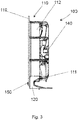
- Fig. 1 shows a wall ring axial fan in a conventional design in a three-dimensional representation.
- the fan 140 is held in a wall ring serving as a fastening device 110 via holding means 111.
- the fastening device 110 has a collar 112 and a flange 119.
- First fastening geometries 115 in the form of bores are provided in the flange 119.
- the wall ring axial fan can be inserted into an annular cutout, for example of a heat exchanger wall, and can be connected to the heat exchanger wall, for example, with screws which are inserted through the first fastening geometries 115 and screwed into the heat exchanger wall.
- Fig. 2 shows a wall ring axial fan with a fastening system 100 according to the invention in a plan view.
- the fan 140 is held in a wall ring serving as a fastening device 110 via holding means 111.
- the fastening device 110 has a collar 112 and a flange 119.
- First fastening geometries 115 in the form of bores are provided in the flange 119.
- the wall ring axial fan can be inserted into an annular cutout, for example of a heat exchanger wall, and can be connected to the heat exchanger wall, for example, with screws which are inserted through the first fastening geometries 115 and screwed into the heat exchanger wall.
- the fastening system 100 has a holding device 120, which is designed as an angle holder and by means of which the wall ring axial fan can be fastened, for example, to a base plate of a heat exchanger unit.
- the wall ring axial fan can be adapted to customer-specific installation situations, such as different installation heights or different fastening positions, by using different holding devices 120, without changing the underlying wall ring axial fan itself.
- the holding device 120 has two grooves as the second indexing means 122, the fastening device 110 having first indexing means 113.
- These first indexing means 113 consist of the extension of the holding means 111, which protrude beyond the outer diameter of the collar 112.
- the grooves as second indexing means 122 can first be inserted into the first indexing means 113.
- the fastening device 110 has two first guides 117 in the form of dovetail guides, into which corresponding second guides 121 on the holding device 120 are inserted in the assembled state. Before the guides 117, 121 come into engagement, the indexing means 113, 122 are engaged, as a result of which the guides 117, 121 find one another more easily and assembly is simplified.
- the fits of the indexing means 113, 122 have more play than those of the guides 117, 121.
- the guides 117, 121 have bevels in the axial direction, as a result of which they are easy to assemble and are nevertheless operatively connected to one another without play in their end position after assembly.
- Fig. 3 shows a wall ring axial fan with a fastening system, which is not part of the present invention, in a side view.
- Holding device 120 and fastening device 110 are assembled with one another and fixed to one another in this position by means of a screw 150 which is screwed through a hole in the fastening device 110 as the first fixing geometry into a blind hole in the holding device 120 as the second fixing geometry 125.
- Fig. 4 shows a detail from a fastening device of a fastening system 100 according to the invention in a three-dimensional representation.
- Two second fastening geometries 116 can be clearly seen in this illustration. These each consist of an axial undercut, onto which the holding device 120 can be pushed and thus fastened.
- the second Fastening geometries 116 each have a dovetail guide as the first guide 117.
- the flange 119 of the fastening device 110 can be seen in this illustration.
- a first fastening geometry 115 in the form of a through hole is located in the flange 119. This bore also serves as the first fixing geometry 118.
- the bore is the first fastening geometry 115 in the event that the wall ring axial fan is installed in a conventional manner in an annular cutout in a wall.
- the wall ring axial fan can be fastened in the ring-shaped cutout with a screw which is passed through this hole and screwed into the wall.
- the same bore serves as the first fixing geometry 118, whereby a screw 150 can be inserted through it, which in the second fixing geometry 125 of the holding device 120 (not shown in the figure) can be screwed when the holding device 120 is mounted in order to fix the holding device 120 to the fastening device 110.
- Fig. 5 shows a holding device 120 of a fastening system 100 according to the invention in a three-dimensional representation from a first perspective.
- the holding device 120 forms a segment of a circle.
- Two second guides 121 in the form of counterparts to a dovetail guide can be seen.
- two second indexing means 122 in the form of axial grooves on the inside diameter of the holding device 120 can be seen.
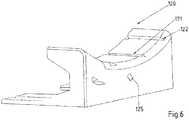
- Fig. 6 shows a holding device 120 of a fastening system 100 according to the invention in a three-dimensional representation from a second perspective.
- Fig. 7 shows a detail from an embodiment of a fastening system 100 according to the invention in a three-dimensional representation.
- a snap hook is provided on the holding device 120 as the second fixing geometry 125, which snaps behind the flange 119 of the fastening device 110 in the assembled state of the holding device 120, which acts as the first fixing geometry 118 in this embodiment.
- a screw 150 or another additional part for fixing the holding device 120 to the fastening device 110 can thus be dispensed with.
Description
Die Erfindung betrifft eine Befestigungsvorrichtung eines Lüfters, insbesondere eines Wandring-Axial-Ventilators.The invention relates to a fastening device for a fan, in particular a wall ring axial fan.
Ein verbreiteter Anwendungsfall von Lüftern ist die Verwendung als Kühlvorrichtung an abwärmeproduzierenden Geräten. Solche abwärmeproduzierenden Geräte können beispielsweise Wärmetauscher sein, wobei der Lüfter unmittelbar an dem Wärmetauscher oder an einem den Wärmetauscher aufnehmenden Gehäuse befestigt wird. Lüfter für solche Anwendungsfälle können einen Wandring aufweisen, über den die Befestigung vorgenommen wird. Dazu sind Bohrungen und teilweise Gewindeeinsätze an der Stirnseite des Wandringes vorgesehen. Diese Befestigungsart ist beispielsweise bei den bisher meist eingesetzten Lamellen-Wärmetauschern weit verbreitet.A common application of fans is the use as a cooling device on waste heat-producing devices. Such waste heat-producing devices can, for example, be heat exchangers, the fan being attached directly to the heat exchanger or to a housing accommodating the heat exchanger. Fans for such applications can have a wall ring over which the attachment is made. For this purpose, holes and partially threaded inserts are provided on the end face of the wall ring. This type of attachment is widely used, for example, in the finned heat exchangers that have mostly been used to date.
Aus Kostengründen tauchen am Markt aber auch zunehmend andere Bauformen von Wärmetauschern auf, die einen direkten Anbau eines Lüfters über den Wandring nicht zulassen. Bekannte Lösungen für dieses Problem, bei dem die Befestigung des Antriebsmotors des Ventilators über einen U-Bügel mit dem Bodenblech eines Gerätes unter Verzicht auf einen Wandring erfolgt, haben Nachteile hinsichtlich Wirkungsgrad und Geräuschentwicklung.For cost reasons, however, other types of heat exchangers are increasingly appearing on the market that do not allow a fan to be attached directly via the wall ring. Known solutions to this problem, in which the drive motor of the fan is attached via a U-bracket to the base plate of a device without a wall ring, have disadvantages with regard to efficiency and noise.
So offenbart die deutsche Offenlegungsschrift
Die deutsche Patentschrift
Die US-amerikanische Offenlegungsschrift
Die US-amerikanische Offenlegungsschrift
Aufgabe der Erfindung ist es daher, eine Befestigungsvorrichtung eines Wandring-Axial-Ventilators anzugeben, die in Einsatzfällen einsetzbar ist, in denen der Lüfter an einer anderen Bauform als einem Lamellen-Wärmetauscher unter Beibehaltung des Wandrings befestigt werden soll. Insbesondere soll diese Befestigungsmöglichkeit optional möglich sein, so dass die konventionelle Befestigung des Wandring-Axial-Ventilators weiterhin uneingeschränkt möglich ist.The object of the invention is therefore to provide a fastening device of a wall ring axial fan, which can be used in applications in which the fan is to be fastened to a design other than a lamella heat exchanger while maintaining the wall ring. In particular, this fastening option should be optionally possible, so that the conventional fastening of the wall ring axial fan is still possible without restriction.
Erfindungsgemäß wird diese Aufgabe durch ein Befestigungssystem mit den Merkmalen des unabhängigen Anspruches 1 gelöst. Vorteilhafte Weiterbildungen des Befestigungssystems ergeben sich aus den Unteransprüchen 2 - 6.According to the invention, this object is achieved by a fastening system with the features of independent claim 1. Advantageous further developments of the fastening system result from subclaims 2-6.
Ein erfindungsgemäßes Befestigungssystem ist zur Befestigung eines Wandring-Axial-Ventilators an einem Gerät vorgesehen. Das Befestigungssystem ist mit einem Wandring als Befestigungsvorrichtung, einem Ventilator und einem Haltemittel versehen, wobei die Befestigungsvorrichtung in radialer Richtung um den Ventilator herum vorgesehen ist und der Ventilator über das Haltemittel mit der Befestigungsvorrichtung verbunden ist. Die Befestigungsvorrichtung weist eine erste Befestigungsgeometrie auf. Das Befestigungssystem umfasst die Befestigungsvorrichtung und weist zusätzlich eine Haltevorrichtung auf, wobei die Befestigungsvorrichtung mindestens eine weitere, zweite Befestigungsgeometrie zur Befestigung der Haltevorrichtung an der Befestigungsvorrichtung aufweist. Über die erste Befestigungsgeometrie kann die Befestigungsvorrichtung und damit der Wandring-Axial-Ventilator in herkömmlicher Weise an einem Gerät befestigt werden. Beispielsweise besteht die erste Befestigungsgeometrie aus Bohrungen in einem Flansch der Befestigungsvorrichtung, so dass der Wandring-Axial-Ventilator in eine ringförmige Öffnung wie die Wand eines Wärmetauschers oder eines Wärmetauschergehäuses eingebaut werden und mittels eines Befestigungsmittels, beispielsweise einer Schraube, befestigt werden kann. Die zweite Befestigungsgeometrie dient der Befestigung der Haltevorrichtung an der Befestigungsvorrichtung, so dass der Wandring-Axial-Ventilator über die Haltevorrichtung an einer anderen Bauform eines Geräts als einem Lamellen-Wärmetauscher, beispielsweise an einem Bodenblech einer Wärmetauscher-Einheit, befestigt werden kann. Ein und derselbe Wandring-Axial-Ventilator kann durch die Verwendung unterschiedlicher Haltevorrichtung an kundenspezifische Einbausituationen wie beispielsweise unterschiedliche Einbauhöhen oder unterschiedliche Befestigungspositionen, angepasst werden, ohne den zugrundeliegenden Wandring-Axial-Ventilator selbst zu verändern.A fastening system according to the invention is provided for fastening a wall ring axial fan to a device. The fastening system is provided with a wall ring as a fastening device, a fan and a holding means, the fastening device being provided in the radial direction around the fan and the fan being connected to the fastening device via the holding means. The fastening device has a first fastening geometry. The fastening system comprises the fastening device and additionally has a holding device, the fastening device having at least one further, second fastening geometry for fastening the holding device to the fastening device. The fastening device and thus the wall ring axial fan can be fastened to a device in a conventional manner via the first fastening geometry. For example, the first fastening geometry consists of bores in a flange of the fastening device, so that the wall ring axial fan can be installed in an annular opening such as the wall of a heat exchanger or a heat exchanger housing and can be fastened by means of a fastening means, for example a screw. The second fastening geometry is used to fasten the holding device to the fastening device, so that the wall ring axial fan, via the holding device, is designed on a construction of a device other than a lamella heat exchanger, for example on a base plate of a heat exchanger unit. can be attached. One and the same wall ring axial fan can be adapted to customer-specific installation situations such as different installation heights or different mounting positions by using different holding devices, without changing the underlying wall ring axial fan itself.
Die zweite Befestigungsgeometrie ist am Umfang der Befestigungsvorrichtung vorgesehen. Erfindungsgemäß weist die Befestigungsvorrichtung an ihrem Umfang einen Kragen auf, wobei die zweite Befestigungsgeometrie am Umfang des Kragens vorgesehen ist. Die zweite Befestigungsgeometrie weist eine erste Führung auf, in die die Haltevorrichtung einsteckbar ist, wobei der Außendurchmesser der ersten Führung höchstens gleich groß ist wie der maximale Außendurchmesser der Befestigungsvorrichtung. Damit ist eine Montage in eine ringförmige Öffnung trotz der zusätzlichen ersten Führung behinderungsfrei möglich. Die erste Führung ist dabei als Schwalbenschwanzführung ausgeführt und kann beispielsweise eine Trapezform oder eine Zylinderform aufweisen.The second fastening geometry is provided on the circumference of the fastening device. According to the invention, the fastening device has a collar on its circumference, the second fastening geometry being provided on the circumference of the collar. The second fastening geometry has a first guide into which the holding device can be inserted, the outer diameter of the first guide being at most the same size as the maximum outer diameter of the fastening device. Installation in an annular opening is thus possible without hindrance despite the additional first guide. The first guide is designed as a dovetail guide and can have a trapezoidal shape or a cylindrical shape, for example.
Erfindungsgemäß weist die Haltevorrichtung mindestens eine zweite Führung auf, die mit der ersten Führung der zweiten Befestigungsgeometrie wirkverbindbar ist. Beispielsweise kann die Haltevorrichtung mit ihrer zweiten Führung in die erste Führung der Befestigungsvorrichtung eingeschoben werden. Die Führungen von der zweiten Befestigungsgeometrie und der Haltevorrichtung weisen sich entsprechende Schrägen in axialer Richtung auf. Dadurch können die beiden Teile leicht gefügt werden und sitzen in der Endlage dennoch spielfrei. Darüber hinaus können die Schrägen als Entformungsschrägen dienen, wenn die Teile gegossen sind. Beispielsweise können die Befestigungsvorrichtung als auch die Haltevorrichtung aus einem Kunststoff, beispielsweise einem thermoplastischen oder auch einem duroplastischen Kunststoff, hergestellt sein. Dafür bietet sich das Spritzgußverfahren an, bei dem für die Entformung aus der Form Schrägen in Entformungsrichtung an den Spritzgussteilen vorteilhaft sind.According to the invention, the holding device has at least one second guide which can be operatively connected to the first guide of the second fastening geometry. For example, the holding device can be inserted with its second guide into the first guide of the fastening device. The guides of the second fastening geometry and the holding device have corresponding bevels in the axial direction. As a result, the two parts can be easily joined and still sit without play in the end position. In addition, the bevels can serve as draft angles when the parts are cast. For example, the fastening device and the holding device can be made of a plastic, for example a thermoplastic or also a thermosetting plastic. The injection molding process lends itself to this, in which bevels in the demolding direction on the injection molded parts are advantageous for demolding from the mold.
In einer weiteren vorteilhaften Ausführungsform weist die Befestigungsvorrichtung mindestens ein erstes Indexierungsmittel auf, wobei die Haltevorrichtung ein zweites Indexierungsmittel aufweist, das mit dem ersten Indexierungsmittel bei der Montage von Haltevorrichtung mit der Befestigungsvorrichtung zusammen wirkt. Beispielsweise kann das erste Indexierungsmittel einen axialen Vorsprung an der Außengeometrie des Kragens der Befestigungsvorrichtung aufweisen, während das zweite Indexierungsmittel eine in axialer Richtung verlaufende Nut am Innendurchmesser der Haltevorrichtung aufweist. So kann das erste Indexierungsmittel beispielsweise aus der Verlängerung mindestens eines Haltemittels bestehen, das über den Außendurchmesser des Kragens hinausragt. Das zweite Indexierungsmittel kann zunächst in das erste Indexierungsmittel eingeschoben werden, bevor die Führungen in Eingriff kommen. Durch das Einschieben der Indexierungsmittel können die Führungen leichter zueinander finden und die Montage wird vereinfacht.In a further advantageous embodiment, the fastening device has at least one first indexing means, the holding device having a second indexing means which interacts with the first indexing means during the mounting of the holding device with the fastening device. For example, the first indexing means can have an axial projection on the outer geometry of the collar of the fastening device, while the second indexing means has a groove running in the axial direction Has inner diameter of the holding device. For example, the first indexing means can consist of the extension of at least one holding means which projects beyond the outer diameter of the collar. The second indexing means can first be inserted into the first indexing means before the guides engage. By inserting the indexing means, the guides can find each other more easily and assembly is simplified.
In einer weiteren vorteilhaften Ausführungsform weist die Befestigungsvorrichtung eine erste Fixierungsgeometrie und die Haltevorrichtung eine zweite Fixierungsgeometrie auf, wobei die Fixierungsgeometrien im montierten Zustand wirkverbindbar sind. Die erste Befestigungsgeometrie weist erfindungsgemäß einen als eine erste Fixierungsgeometrie wirkenden Flansch auf und eine zweite Fixierungsgeometrie weist einen Schnapphaken an der Haltevorrichtung auf, wobei der Schnapphaken hinter dem Flansch einschnappen kann, wenn die Haltevorrichtung an der Befestigungsvorrichtung montiert ist.In a further advantageous embodiment, the fastening device has a first fixation geometry and the holding device has a second fixation geometry, the fixation geometries being operatively connectable in the assembled state. According to the invention, the first fastening geometry has a flange which acts as a first fastening geometry and a second fastening geometry has a snap hook on the holding device, the snap hook being able to snap behind the flange when the holding device is mounted on the fastening device.
Weitere Vorteile, Besonderheiten und zweckmäßige Weiterbildungen der Erfindung ergeben sich aus den Unteransprüchen und der nachfolgenden Darstellung bevorzugter Ausführungsbeispiele anhand der Abbildungen.Further advantages, special features and expedient developments of the invention result from the subclaims and the following illustration of preferred exemplary embodiments with the aid of the figures.
Von den Abbildungen zeigt:
- Fig. 1
- einen Wandring-Axial-Ventilator in konventioneller Bauform in einer dreidimensionalen Darstellung
- Fig. 2
- einen Wandring-Axial-Ventilator mit einem erfindungsgemäßen Befestigungssystem in einer Draufsicht
- Fig. 3
- einen Wandring-Axial-Ventilator mit einem erfindungsgemäßen Befestigungssystem in einer Seitenansicht
- Fig. 4
- einen Ausschnitt aus einer Befestigungsvorrichtung eines erfindungsgemäßen Befestigungssystems in einer dreidimensionalen Darstellung
- Fig. 5
- eine Haltevorrichtung eines erfindungsgemäßen Befestigungssystems in einer dreidimensionalen Darstellung aus einer ersten Perspektive
- Fig. 6
- eine Haltevorrichtung eines erfindungsgemäßen Befestigungssystems in einer dreidimensionalen Darstellung aus einer zweiten Perspektive
- Fig. 7
- einen Ausschnitt aus einer Ausführungsform eines erfindungsgemäßen Befestigungssystems in einer dreidimensionalen Darstellung
- Fig. 1
- a wall ring axial fan in a conventional design in a three-dimensional representation
- Fig. 2
- a wall ring axial fan with a fastening system according to the invention in a plan view
- Fig. 3
- a wall ring axial fan with a fastening system according to the invention in a side view
- Fig. 4
- a section of a fastening device of a fastening system according to the invention in a three-dimensional representation
- Fig. 5
- a holding device of a fastening system according to the invention in a three-dimensional representation from a first perspective
- Fig. 6
- a holding device of a fastening system according to the invention in a three-dimensional representation from a second perspective
- Fig. 7
- a section of an embodiment of a fastening system according to the invention in a three-dimensional representation
Die hier gezeigten Ausführungsformen stellen nur Beispiele für die vorliegende Erfindung dar und dürfen daher nicht einschränkend verstanden werden. Alternative durch den Fachmann in Erwägung gezogene Ausführungsformen sind gleichermaßen vom Schutzbereich der vorliegenden Erfindung umfasst.The embodiments shown here are only examples of the present invention and should therefore not be understood as restrictive. Alternative embodiments contemplated by those skilled in the art are equally within the scope of the present invention.
- 100100
- BefestigungssystemFastening system
- 110110
- Befestigungsvorrichtung, WandringFastening device, wall ring
- 111111
- HaltemittelHolding means
- 112112
- Kragencollar
- 113113
- erstes Indexierungsmittelfirst indexing agent
- 115115
- erste Befestigungsgeometriefirst mounting geometry
- 116116
- zweite Befestigungsgemometriesecond mounting geometry
- 117117
- erste Führungfirst tour
- 118118
- erste Fixierungsgeometriefirst fixation geometry
- 119119
- Flanschflange
- 120120
- HaltevorrichtungHolding device
- 121121
- zweite Führungsecond tour
- 122122
- zweites Indizierungsmittelsecond indexing means
- 125125
- zweite Fixierungsgeometriesecond fixation geometry
- 140140
- Ventilatorfan
- 150150
- Schraubescrew
Claims (6)
- A fastening system (100) for fastening a wall ring axial ventilator comprising a wall ring as fastening device (110), a ventilator (140), and holding means (111), to an apparatus, wherein the fastening device (110) is provided in the radial direction around the ventilator (140) and the ventilator (140) is connected to the fastening device (110) by means of the holding means (111), and wherein the fastening device (110) has a first fastening geometry (115), wherein the fastening system (100) comprises the fastening device (110) and additionally has a holding device (120), wherein the fastening device (110) has at least a second fastening geometry (116) for fastening the holding device (120) to the fastening device (110), the second fastening geometry (116) is provided at the circumference of the fastening device (110), wherein the fastening device (110) has a collar (112) at its circumference, at the circumference of which the second fastening geometry (116) is provided, and has a first guide (117) in the form of a dovetail guide, into which the holding device (120) can be inserted, wherein the outer diameter of the first guide (117) is maximally equal to the maximal outer diameter of the fastening device (110), and wherein the holding device (120) has at least a second guide (121), which can be operatively connected to the first guide (117) of the second fastening geometry (116), and wherein the first and second guide (117, 121) of the second fastening geometry (116) and of the holding device (120) have corresponding bevels in the axial direction, wherein the first fastening geometry (115) has a flange (119), which acts as a first fixing geometry (118), and a second fixing geometry (125) has a snap-in hook at the holding device (120).
- The fastening system (100) according to claim 1,
characterized in
that the dovetail guide has a trapezoidal shape. - The fastening system (100) according to claim 1,
characterized in
that the dovetail guide has a cylinder shape. - The fastening system (100) according to any one of the preceding claims,
characterized in
that the fastening device (110) has at least a first indexing means (113), wherein the holding device (120) has a second indexing means (122), which interacts with the first indexing means (113) in response to the assembly of holding device (120) with the fastening device (113). - The fastening system (100) according to claim 4,
characterized in
that the first indexing means (113) has an axial projection at the outer geometry of the collar (112) of the fastening device (110), while the second indexing means (122) has a groove, which runs in the axial direction, at the inner diameter of the holding device (120). - The fastening system (100) according to any one of the preceding claims,
characterized in
that the first fixing geometry (118) and the second fixing geometry (125) can be operatively connected in the assembled state.
Applications Claiming Priority (1)
| Application Number | Priority Date | Filing Date | Title |
|---|---|---|---|
| DE102014207365.0A DE102014207365A1 (en) | 2014-04-16 | 2014-04-16 | fan mounting |
Publications (2)
| Publication Number | Publication Date |
|---|---|
| EP2933495A1 EP2933495A1 (en) | 2015-10-21 |
| EP2933495B1 true EP2933495B1 (en) | 2020-07-01 |
Family
ID=53005467
Family Applications (1)
| Application Number | Title | Priority Date | Filing Date |
|---|---|---|---|
| EP15163007.6A Active EP2933495B1 (en) | 2014-04-16 | 2015-04-09 | Fan attachment |
Country Status (4)
| Country | Link |
|---|---|
| US (1) | US20150300373A1 (en) |
| EP (1) | EP2933495B1 (en) |
| CN (1) | CN105003466A (en) |
| DE (1) | DE102014207365A1 (en) |
Families Citing this family (4)
| Publication number | Priority date | Publication date | Assignee | Title |
|---|---|---|---|---|
| CN104564845B (en) * | 2013-10-11 | 2017-07-21 | 英业达科技有限公司 | Fixture and its fan structure |
| GB201517171D0 (en) * | 2015-09-29 | 2015-11-11 | Rolls Royce Plc | A casing for a gas turbine engine and a method of manufacturing such a casing |
| US11846301B2 (en) | 2016-03-15 | 2023-12-19 | Trane International Inc. | Aligning a centerline of a motor shaft in a fan assembly |
| JP7162045B2 (en) * | 2018-02-22 | 2022-10-27 | ミネベアミツミ株式会社 | Blower device |
Family Cites Families (12)
| Publication number | Priority date | Publication date | Assignee | Title |
|---|---|---|---|---|
| US6358087B1 (en) * | 2000-10-16 | 2002-03-19 | General Motors Corporation | Snap-fit electrical connector |
| DE202005011514U1 (en) * | 2005-07-19 | 2005-10-13 | Arctic-Cooling Switzerland Ag | Computer cooling fan with vaned rotor, driving motor and rigid housing part for securing to part to be cooled, with motor and housing part coupled by damping members |
| TWM334886U (en) * | 2007-12-12 | 2008-06-21 | Taiwei Fan Technology Co Ltd | Combination type miniature axial-flow fan |
| US20100111698A1 (en) * | 2008-11-06 | 2010-05-06 | Bryce Wiedeman | Fan with locking ring |
| CN201666266U (en) * | 2009-12-07 | 2010-12-08 | 甘肃省机械科学研究院 | Fan used for fruit/vegetable belt type dryer |
| DE102010045899B3 (en) * | 2010-09-17 | 2012-02-16 | Ingo Schehr | Fan unit with an electric axial fan |
| CN102905503B (en) * | 2011-07-29 | 2016-06-01 | 深圳市丰巨泰科电子有限公司 | Fan regulates device |
| CN103149971A (en) * | 2011-12-06 | 2013-06-12 | 鸿富锦精密工业(武汉)有限公司 | Fan module |
| JP5945912B2 (en) * | 2012-02-09 | 2016-07-05 | 日本電産株式会社 | fan |
| DE202012103921U1 (en) * | 2012-10-12 | 2014-01-16 | Ebm-Papst St. Georgen Gmbh & Co. Kg | Mounting element for mounting a fan housing and fan housing |
| US9222479B2 (en) * | 2012-08-21 | 2015-12-29 | Cooler Master Development Corporation | Fan and fan frame thereof |
| DE102012109516B4 (en) * | 2012-10-08 | 2016-08-04 | Ebm-Papst Mulfingen Gmbh & Co. Kg | "Carrier element for a fan and ventilator equipped therewith" |
-
2014
- 2014-04-16 DE DE102014207365.0A patent/DE102014207365A1/en not_active Withdrawn
-
2015
- 2015-04-09 EP EP15163007.6A patent/EP2933495B1/en active Active
- 2015-04-14 CN CN201510176178.6A patent/CN105003466A/en active Pending
- 2015-04-15 US US14/687,111 patent/US20150300373A1/en not_active Abandoned
Non-Patent Citations (1)
| Title |
|---|
| None * |
Also Published As
| Publication number | Publication date |
|---|---|
| CN105003466A (en) | 2015-10-28 |
| US20150300373A1 (en) | 2015-10-22 |
| DE102014207365A1 (en) | 2015-10-22 |
| EP2933495A1 (en) | 2015-10-21 |
Similar Documents
| Publication | Publication Date | Title |
|---|---|---|
| DE102010045899B3 (en) | Fan unit with an electric axial fan | |
| DE102009039783B4 (en) | centrifugal blower | |
| EP2933495B1 (en) | Fan attachment | |
| EP2242930A1 (en) | Compact fan | |
| EP2904333B1 (en) | Support element for a fan and fan equipped therewith | |
| DE10253227A1 (en) | Fans, especially device fans | |
| DE1428225B2 (en) | Centrifugal fan | |
| DE102016217449A1 (en) | Electric motor with a mounting arrangement, gear unit, electric geared motor and seat | |
| EP3158626A2 (en) | Electric motor comprising a rotor, a stator and an electronic housing as well as fan wheel for an electric motor | |
| EP3586415B1 (en) | Plug coupling with strain relief for a connecting cable | |
| DE102014116727A1 (en) | Fan unit with a fan housing | |
| DE102007010465B4 (en) | Fan assembly and mounting assembly for selbige | |
| DE102007014508B4 (en) | Coil device for wire, in particular for welding wire | |
| DE3210164C2 (en) | Device for fastening a fan in a housing wall of an electrical device | |
| EP2525103B1 (en) | Ventilator assembly | |
| EP2750269B1 (en) | Pump power unit | |
| DE102012100471A1 (en) | ventilation arrangement | |
| DE102020004844A1 (en) | Rotor for electric motors and electric motor with rotor | |
| DE10330315B4 (en) | filter Fans | |
| EP0591665B1 (en) | Casing for an electrical apparatus | |
| WO2005073660A1 (en) | Fan drive fastening system, particularly for a motor vehicle | |
| DE69816204T2 (en) | Device for supporting the motor unit of a fan | |
| WO2004084380A1 (en) | Mounting a motor on a carrier | |
| DE2036578C3 (en) | Coupling, especially for table and wall fans | |
| DE102015102348B4 (en) | Device fan cover |
Legal Events
| Date | Code | Title | Description |
|---|---|---|---|
| PUAI | Public reference made under article 153(3) epc to a published international application that has entered the european phase |
Free format text: ORIGINAL CODE: 0009012 |
|
| AK | Designated contracting states |
Kind code of ref document: A1 Designated state(s): AL AT BE BG CH CY CZ DE DK EE ES FI FR GB GR HR HU IE IS IT LI LT LU LV MC MK MT NL NO PL PT RO RS SE SI SK SM TR |
|
| AX | Request for extension of the european patent |
Extension state: BA ME |
|
| 17P | Request for examination filed |
Effective date: 20160421 |
|
| RBV | Designated contracting states (corrected) |
Designated state(s): AL AT BE BG CH CY CZ DE DK EE ES FI FR GB GR HR HU IE IS IT LI LT LU LV MC MK MT NL NO PL PT RO RS SE SI SK SM TR |
|
| STAA | Information on the status of an ep patent application or granted ep patent |
Free format text: STATUS: EXAMINATION IS IN PROGRESS |
|
| 17Q | First examination report despatched |
Effective date: 20180502 |
|
| GRAP | Despatch of communication of intention to grant a patent |
Free format text: ORIGINAL CODE: EPIDOSNIGR1 |
|
| STAA | Information on the status of an ep patent application or granted ep patent |
Free format text: STATUS: GRANT OF PATENT IS INTENDED |
|
| INTG | Intention to grant announced |
Effective date: 20200213 |
|
| GRAS | Grant fee paid |
Free format text: ORIGINAL CODE: EPIDOSNIGR3 |
|
| GRAA | (expected) grant |
Free format text: ORIGINAL CODE: 0009210 |
|
| STAA | Information on the status of an ep patent application or granted ep patent |
Free format text: STATUS: THE PATENT HAS BEEN GRANTED |
|
| AK | Designated contracting states |
Kind code of ref document: B1 Designated state(s): AL AT BE BG CH CY CZ DE DK EE ES FI FR GB GR HR HU IE IS IT LI LT LU LV MC MK MT NL NO PL PT RO RS SE SI SK SM TR |
|
| REG | Reference to a national code |
Ref country code: CH Ref legal event code: EP Ref country code: AT Ref legal event code: REF Ref document number: 1286444 Country of ref document: AT Kind code of ref document: T Effective date: 20200715 |
|
| REG | Reference to a national code |
Ref country code: IE Ref legal event code: FG4D Free format text: LANGUAGE OF EP DOCUMENT: GERMAN |
|
| REG | Reference to a national code |
Ref country code: DE Ref legal event code: R096 Ref document number: 502015012892 Country of ref document: DE |
|
| REG | Reference to a national code |
Ref country code: SE Ref legal event code: TRGR |
|
| REG | Reference to a national code |
Ref country code: NL Ref legal event code: FP |
|
| REG | Reference to a national code |
Ref country code: LT Ref legal event code: MG4D |
|
| PG25 | Lapsed in a contracting state [announced via postgrant information from national office to epo] |
Ref country code: BG Free format text: LAPSE BECAUSE OF FAILURE TO SUBMIT A TRANSLATION OF THE DESCRIPTION OR TO PAY THE FEE WITHIN THE PRESCRIBED TIME-LIMIT Effective date: 20201001 |
|
| PG25 | Lapsed in a contracting state [announced via postgrant information from national office to epo] |
Ref country code: ES Free format text: LAPSE BECAUSE OF FAILURE TO SUBMIT A TRANSLATION OF THE DESCRIPTION OR TO PAY THE FEE WITHIN THE PRESCRIBED TIME-LIMIT Effective date: 20200701 Ref country code: NO Free format text: LAPSE BECAUSE OF FAILURE TO SUBMIT A TRANSLATION OF THE DESCRIPTION OR TO PAY THE FEE WITHIN THE PRESCRIBED TIME-LIMIT Effective date: 20201001 Ref country code: PT Free format text: LAPSE BECAUSE OF FAILURE TO SUBMIT A TRANSLATION OF THE DESCRIPTION OR TO PAY THE FEE WITHIN THE PRESCRIBED TIME-LIMIT Effective date: 20201102 Ref country code: LT Free format text: LAPSE BECAUSE OF FAILURE TO SUBMIT A TRANSLATION OF THE DESCRIPTION OR TO PAY THE FEE WITHIN THE PRESCRIBED TIME-LIMIT Effective date: 20200701 Ref country code: HR Free format text: LAPSE BECAUSE OF FAILURE TO SUBMIT A TRANSLATION OF THE DESCRIPTION OR TO PAY THE FEE WITHIN THE PRESCRIBED TIME-LIMIT Effective date: 20200701 Ref country code: GR Free format text: LAPSE BECAUSE OF FAILURE TO SUBMIT A TRANSLATION OF THE DESCRIPTION OR TO PAY THE FEE WITHIN THE PRESCRIBED TIME-LIMIT Effective date: 20201002 Ref country code: FI Free format text: LAPSE BECAUSE OF FAILURE TO SUBMIT A TRANSLATION OF THE DESCRIPTION OR TO PAY THE FEE WITHIN THE PRESCRIBED TIME-LIMIT Effective date: 20200701 |
|
| PG25 | Lapsed in a contracting state [announced via postgrant information from national office to epo] |
Ref country code: LV Free format text: LAPSE BECAUSE OF FAILURE TO SUBMIT A TRANSLATION OF THE DESCRIPTION OR TO PAY THE FEE WITHIN THE PRESCRIBED TIME-LIMIT Effective date: 20200701 Ref country code: PL Free format text: LAPSE BECAUSE OF FAILURE TO SUBMIT A TRANSLATION OF THE DESCRIPTION OR TO PAY THE FEE WITHIN THE PRESCRIBED TIME-LIMIT Effective date: 20200701 Ref country code: RS Free format text: LAPSE BECAUSE OF FAILURE TO SUBMIT A TRANSLATION OF THE DESCRIPTION OR TO PAY THE FEE WITHIN THE PRESCRIBED TIME-LIMIT Effective date: 20200701 Ref country code: IS Free format text: LAPSE BECAUSE OF FAILURE TO SUBMIT A TRANSLATION OF THE DESCRIPTION OR TO PAY THE FEE WITHIN THE PRESCRIBED TIME-LIMIT Effective date: 20201101 |
|
| REG | Reference to a national code |
Ref country code: DE Ref legal event code: R097 Ref document number: 502015012892 Country of ref document: DE |
|
| PG25 | Lapsed in a contracting state [announced via postgrant information from national office to epo] |
Ref country code: DK Free format text: LAPSE BECAUSE OF FAILURE TO SUBMIT A TRANSLATION OF THE DESCRIPTION OR TO PAY THE FEE WITHIN THE PRESCRIBED TIME-LIMIT Effective date: 20200701 Ref country code: EE Free format text: LAPSE BECAUSE OF FAILURE TO SUBMIT A TRANSLATION OF THE DESCRIPTION OR TO PAY THE FEE WITHIN THE PRESCRIBED TIME-LIMIT Effective date: 20200701 Ref country code: RO Free format text: LAPSE BECAUSE OF FAILURE TO SUBMIT A TRANSLATION OF THE DESCRIPTION OR TO PAY THE FEE WITHIN THE PRESCRIBED TIME-LIMIT Effective date: 20200701 Ref country code: SM Free format text: LAPSE BECAUSE OF FAILURE TO SUBMIT A TRANSLATION OF THE DESCRIPTION OR TO PAY THE FEE WITHIN THE PRESCRIBED TIME-LIMIT Effective date: 20200701 |
|
| PLBE | No opposition filed within time limit |
Free format text: ORIGINAL CODE: 0009261 |
|
| STAA | Information on the status of an ep patent application or granted ep patent |
Free format text: STATUS: NO OPPOSITION FILED WITHIN TIME LIMIT |
|
| PG25 | Lapsed in a contracting state [announced via postgrant information from national office to epo] |
Ref country code: AL Free format text: LAPSE BECAUSE OF FAILURE TO SUBMIT A TRANSLATION OF THE DESCRIPTION OR TO PAY THE FEE WITHIN THE PRESCRIBED TIME-LIMIT Effective date: 20200701 |
|
| 26N | No opposition filed |
Effective date: 20210406 |
|
| PG25 | Lapsed in a contracting state [announced via postgrant information from national office to epo] |
Ref country code: SK Free format text: LAPSE BECAUSE OF FAILURE TO SUBMIT A TRANSLATION OF THE DESCRIPTION OR TO PAY THE FEE WITHIN THE PRESCRIBED TIME-LIMIT Effective date: 20200701 |
|
| PG25 | Lapsed in a contracting state [announced via postgrant information from national office to epo] |
Ref country code: SI Free format text: LAPSE BECAUSE OF FAILURE TO SUBMIT A TRANSLATION OF THE DESCRIPTION OR TO PAY THE FEE WITHIN THE PRESCRIBED TIME-LIMIT Effective date: 20200701 |
|
| PG25 | Lapsed in a contracting state [announced via postgrant information from national office to epo] |
Ref country code: MC Free format text: LAPSE BECAUSE OF FAILURE TO SUBMIT A TRANSLATION OF THE DESCRIPTION OR TO PAY THE FEE WITHIN THE PRESCRIBED TIME-LIMIT Effective date: 20200701 |
|
| PG25 | Lapsed in a contracting state [announced via postgrant information from national office to epo] |
Ref country code: LU Free format text: LAPSE BECAUSE OF NON-PAYMENT OF DUE FEES Effective date: 20210409 |
|
| REG | Reference to a national code |
Ref country code: BE Ref legal event code: MM Effective date: 20210430 |
|
| PG25 | Lapsed in a contracting state [announced via postgrant information from national office to epo] |
Ref country code: CH Free format text: LAPSE BECAUSE OF NON-PAYMENT OF DUE FEES Effective date: 20210430 Ref country code: LI Free format text: LAPSE BECAUSE OF NON-PAYMENT OF DUE FEES Effective date: 20210430 |
|
| PG25 | Lapsed in a contracting state [announced via postgrant information from national office to epo] |
Ref country code: IE Free format text: LAPSE BECAUSE OF NON-PAYMENT OF DUE FEES Effective date: 20210409 |
|
| PG25 | Lapsed in a contracting state [announced via postgrant information from national office to epo] |
Ref country code: IS Free format text: LAPSE BECAUSE OF FAILURE TO SUBMIT A TRANSLATION OF THE DESCRIPTION OR TO PAY THE FEE WITHIN THE PRESCRIBED TIME-LIMIT Effective date: 20201101 |
|
| PG25 | Lapsed in a contracting state [announced via postgrant information from national office to epo] |
Ref country code: BE Free format text: LAPSE BECAUSE OF NON-PAYMENT OF DUE FEES Effective date: 20210430 |
|
| PGFP | Annual fee paid to national office [announced via postgrant information from national office to epo] |
Ref country code: CZ Payment date: 20230327 Year of fee payment: 9 |
|
| PG25 | Lapsed in a contracting state [announced via postgrant information from national office to epo] |
Ref country code: HU Free format text: LAPSE BECAUSE OF FAILURE TO SUBMIT A TRANSLATION OF THE DESCRIPTION OR TO PAY THE FEE WITHIN THE PRESCRIBED TIME-LIMIT; INVALID AB INITIO Effective date: 20150409 |
|
| P01 | Opt-out of the competence of the unified patent court (upc) registered |
Effective date: 20230519 |
|
| PG25 | Lapsed in a contracting state [announced via postgrant information from national office to epo] |
Ref country code: CY Free format text: LAPSE BECAUSE OF FAILURE TO SUBMIT A TRANSLATION OF THE DESCRIPTION OR TO PAY THE FEE WITHIN THE PRESCRIBED TIME-LIMIT Effective date: 20200701 |
|
| PGFP | Annual fee paid to national office [announced via postgrant information from national office to epo] |
Ref country code: NL Payment date: 20230417 Year of fee payment: 9 |
|
| PGFP | Annual fee paid to national office [announced via postgrant information from national office to epo] |
Ref country code: IT Payment date: 20230428 Year of fee payment: 9 Ref country code: FR Payment date: 20230417 Year of fee payment: 9 Ref country code: DE Payment date: 20230418 Year of fee payment: 9 |
|
| PGFP | Annual fee paid to national office [announced via postgrant information from national office to epo] |
Ref country code: SE Payment date: 20230419 Year of fee payment: 9 Ref country code: AT Payment date: 20230414 Year of fee payment: 9 |
|
| PGFP | Annual fee paid to national office [announced via postgrant information from national office to epo] |
Ref country code: GB Payment date: 20230420 Year of fee payment: 9 |