EP2933445B1 - An exhaust valve for an internal combustion engine, and a method of strengthening an annular valve seat area in an exhaust valve - Google Patents
An exhaust valve for an internal combustion engine, and a method of strengthening an annular valve seat area in an exhaust valve Download PDFInfo
- Publication number
- EP2933445B1 EP2933445B1 EP15162032.5A EP15162032A EP2933445B1 EP 2933445 B1 EP2933445 B1 EP 2933445B1 EP 15162032 A EP15162032 A EP 15162032A EP 2933445 B1 EP2933445 B1 EP 2933445B1
- Authority
- EP
- European Patent Office
- Prior art keywords
- annular
- valve
- seat area
- valve seat
- exhaust valve
- Prior art date
- Legal status (The legal status is an assumption and is not a legal conclusion. Google has not performed a legal analysis and makes no representation as to the accuracy of the status listed.)
- Not-in-force
Links
- 238000000034 method Methods 0.000 title claims description 19
- 238000002485 combustion reaction Methods 0.000 title claims description 16
- 238000005728 strengthening Methods 0.000 title claims description 8
- 239000000956 alloy Substances 0.000 claims description 38
- 229910045601 alloy Inorganic materials 0.000 claims description 35
- 238000005096 rolling process Methods 0.000 claims description 33
- 239000000463 material Substances 0.000 claims description 29
- 229910001220 stainless steel Inorganic materials 0.000 claims description 9
- 239000010935 stainless steel Substances 0.000 claims description 8
- 238000005260 corrosion Methods 0.000 claims description 6
- 230000007797 corrosion Effects 0.000 claims description 6
- 238000010438 heat treatment Methods 0.000 claims description 6
- 238000003483 aging Methods 0.000 claims description 5
- 230000032683 aging Effects 0.000 claims description 4
- 238000001953 recrystallisation Methods 0.000 claims description 2
- PXHVJJICTQNCMI-UHFFFAOYSA-N Nickel Chemical compound [Ni] PXHVJJICTQNCMI-UHFFFAOYSA-N 0.000 description 22
- 229910052759 nickel Inorganic materials 0.000 description 11
- XEEYBQQBJWHFJM-UHFFFAOYSA-N Iron Chemical compound [Fe] XEEYBQQBJWHFJM-UHFFFAOYSA-N 0.000 description 10
- 229910052804 chromium Inorganic materials 0.000 description 10
- 239000011651 chromium Substances 0.000 description 10
- 229910052710 silicon Inorganic materials 0.000 description 9
- 229910052799 carbon Inorganic materials 0.000 description 8
- 229910052742 iron Inorganic materials 0.000 description 8
- 238000003466 welding Methods 0.000 description 8
- 239000010936 titanium Substances 0.000 description 7
- 229910052719 titanium Inorganic materials 0.000 description 7
- 229910052782 aluminium Inorganic materials 0.000 description 6
- 239000010955 niobium Substances 0.000 description 6
- 238000009826 distribution Methods 0.000 description 5
- 238000005242 forging Methods 0.000 description 5
- 238000003754 machining Methods 0.000 description 4
- 229910052748 manganese Inorganic materials 0.000 description 4
- 239000011572 manganese Substances 0.000 description 4
- 229910052750 molybdenum Inorganic materials 0.000 description 4
- 229910052758 niobium Inorganic materials 0.000 description 4
- 229910052715 tantalum Inorganic materials 0.000 description 4
- 239000010941 cobalt Substances 0.000 description 3
- 229910017052 cobalt Inorganic materials 0.000 description 3
- GUTLYIVDDKVIGB-UHFFFAOYSA-N cobalt atom Chemical compound [Co] GUTLYIVDDKVIGB-UHFFFAOYSA-N 0.000 description 3
- 229910000816 inconels 718 Inorganic materials 0.000 description 3
- 238000004519 manufacturing process Methods 0.000 description 3
- 229910052751 metal Inorganic materials 0.000 description 3
- 239000002184 metal Substances 0.000 description 3
- 229910052698 phosphorus Inorganic materials 0.000 description 3
- 238000003825 pressing Methods 0.000 description 3
- 238000005275 alloying Methods 0.000 description 2
- 229910052796 boron Inorganic materials 0.000 description 2
- 239000012535 impurity Substances 0.000 description 2
- 238000011068 loading method Methods 0.000 description 2
- 150000002739 metals Chemical class 0.000 description 2
- 229910001235 nimonic Inorganic materials 0.000 description 2
- 229910052717 sulfur Inorganic materials 0.000 description 2
- 229910052721 tungsten Inorganic materials 0.000 description 2
- XLYOFNOQVPJJNP-UHFFFAOYSA-N water Substances O XLYOFNOQVPJJNP-UHFFFAOYSA-N 0.000 description 2
- ZOXJGFHDIHLPTG-UHFFFAOYSA-N Boron Chemical compound [B] ZOXJGFHDIHLPTG-UHFFFAOYSA-N 0.000 description 1
- OKTJSMMVPCPJKN-UHFFFAOYSA-N Carbon Chemical compound [C] OKTJSMMVPCPJKN-UHFFFAOYSA-N 0.000 description 1
- VYZAMTAEIAYCRO-UHFFFAOYSA-N Chromium Chemical compound [Cr] VYZAMTAEIAYCRO-UHFFFAOYSA-N 0.000 description 1
- RYGMFSIKBFXOCR-UHFFFAOYSA-N Copper Chemical compound [Cu] RYGMFSIKBFXOCR-UHFFFAOYSA-N 0.000 description 1
- ZOKXTWBITQBERF-UHFFFAOYSA-N Molybdenum Chemical compound [Mo] ZOKXTWBITQBERF-UHFFFAOYSA-N 0.000 description 1
- OAICVXFJPJFONN-UHFFFAOYSA-N Phosphorus Chemical compound [P] OAICVXFJPJFONN-UHFFFAOYSA-N 0.000 description 1
- NINIDFKCEFEMDL-UHFFFAOYSA-N Sulfur Chemical compound [S] NINIDFKCEFEMDL-UHFFFAOYSA-N 0.000 description 1
- RTAQQCXQSZGOHL-UHFFFAOYSA-N Titanium Chemical compound [Ti] RTAQQCXQSZGOHL-UHFFFAOYSA-N 0.000 description 1
- 239000004411 aluminium Substances 0.000 description 1
- XAGFODPZIPBFFR-UHFFFAOYSA-N aluminium Chemical compound [Al] XAGFODPZIPBFFR-UHFFFAOYSA-N 0.000 description 1
- 238000013459 approach Methods 0.000 description 1
- 229910000963 austenitic stainless steel Inorganic materials 0.000 description 1
- 230000015572 biosynthetic process Effects 0.000 description 1
- 238000010288 cold spraying Methods 0.000 description 1
- 229910052802 copper Inorganic materials 0.000 description 1
- 239000010949 copper Substances 0.000 description 1
- 230000007423 decrease Effects 0.000 description 1
- 230000008021 deposition Effects 0.000 description 1
- 238000005755 formation reaction Methods 0.000 description 1
- 239000000446 fuel Substances 0.000 description 1
- 238000000227 grinding Methods 0.000 description 1
- 229910001026 inconel Inorganic materials 0.000 description 1
- WPBNNNQJVZRUHP-UHFFFAOYSA-L manganese(2+);methyl n-[[2-(methoxycarbonylcarbamothioylamino)phenyl]carbamothioyl]carbamate;n-[2-(sulfidocarbothioylamino)ethyl]carbamodithioate Chemical compound [Mn+2].[S-]C(=S)NCCNC([S-])=S.COC(=O)NC(=S)NC1=CC=CC=C1NC(=S)NC(=O)OC WPBNNNQJVZRUHP-UHFFFAOYSA-L 0.000 description 1
- 239000003595 mist Substances 0.000 description 1
- 239000011733 molybdenum Substances 0.000 description 1
- GUCVJGMIXFAOAE-UHFFFAOYSA-N niobium atom Chemical compound [Nb] GUCVJGMIXFAOAE-UHFFFAOYSA-N 0.000 description 1
- 239000011574 phosphorus Substances 0.000 description 1
- 239000013074 reference sample Substances 0.000 description 1
- 238000000926 separation method Methods 0.000 description 1
- 239000010703 silicon Substances 0.000 description 1
- 229910001256 stainless steel alloy Inorganic materials 0.000 description 1
- 238000005482 strain hardening Methods 0.000 description 1
- 239000011593 sulfur Substances 0.000 description 1
- WFKWXMTUELFFGS-UHFFFAOYSA-N tungsten Chemical compound [W] WFKWXMTUELFFGS-UHFFFAOYSA-N 0.000 description 1
- 239000010937 tungsten Substances 0.000 description 1
Images


Classifications
-
- F—MECHANICAL ENGINEERING; LIGHTING; HEATING; WEAPONS; BLASTING
- F01—MACHINES OR ENGINES IN GENERAL; ENGINE PLANTS IN GENERAL; STEAM ENGINES
- F01L—CYCLICALLY OPERATING VALVES FOR MACHINES OR ENGINES
- F01L3/00—Lift-valve, i.e. cut-off apparatus with closure members having at least a component of their opening and closing motion perpendicular to the closing faces; Parts or accessories thereof
- F01L3/02—Selecting particular materials for valve-members or valve-seats; Valve-members or valve-seats composed of two or more materials
-
- C—CHEMISTRY; METALLURGY
- C21—METALLURGY OF IRON
- C21D—MODIFYING THE PHYSICAL STRUCTURE OF FERROUS METALS; GENERAL DEVICES FOR HEAT TREATMENT OF FERROUS OR NON-FERROUS METALS OR ALLOYS; MAKING METAL MALLEABLE, e.g. BY DECARBURISATION OR TEMPERING
- C21D1/00—General methods or devices for heat treatment, e.g. annealing, hardening, quenching or tempering
- C21D1/18—Hardening; Quenching with or without subsequent tempering
-
- C—CHEMISTRY; METALLURGY
- C21—METALLURGY OF IRON
- C21D—MODIFYING THE PHYSICAL STRUCTURE OF FERROUS METALS; GENERAL DEVICES FOR HEAT TREATMENT OF FERROUS OR NON-FERROUS METALS OR ALLOYS; MAKING METAL MALLEABLE, e.g. BY DECARBURISATION OR TEMPERING
- C21D8/00—Modifying the physical properties by deformation combined with, or followed by, heat treatment
-
- C—CHEMISTRY; METALLURGY
- C22—METALLURGY; FERROUS OR NON-FERROUS ALLOYS; TREATMENT OF ALLOYS OR NON-FERROUS METALS
- C22C—ALLOYS
- C22C19/00—Alloys based on nickel or cobalt
- C22C19/03—Alloys based on nickel or cobalt based on nickel
- C22C19/05—Alloys based on nickel or cobalt based on nickel with chromium
- C22C19/058—Alloys based on nickel or cobalt based on nickel with chromium without Mo and W
-
- C—CHEMISTRY; METALLURGY
- C22—METALLURGY; FERROUS OR NON-FERROUS ALLOYS; TREATMENT OF ALLOYS OR NON-FERROUS METALS
- C22C—ALLOYS
- C22C38/00—Ferrous alloys, e.g. steel alloys
-
- C—CHEMISTRY; METALLURGY
- C22—METALLURGY; FERROUS OR NON-FERROUS ALLOYS; TREATMENT OF ALLOYS OR NON-FERROUS METALS
- C22C—ALLOYS
- C22C38/00—Ferrous alloys, e.g. steel alloys
- C22C38/08—Ferrous alloys, e.g. steel alloys containing nickel
-
- C—CHEMISTRY; METALLURGY
- C22—METALLURGY; FERROUS OR NON-FERROUS ALLOYS; TREATMENT OF ALLOYS OR NON-FERROUS METALS
- C22C—ALLOYS
- C22C38/00—Ferrous alloys, e.g. steel alloys
- C22C38/18—Ferrous alloys, e.g. steel alloys containing chromium
-
- B—PERFORMING OPERATIONS; TRANSPORTING
- B21—MECHANICAL METAL-WORKING WITHOUT ESSENTIALLY REMOVING MATERIAL; PUNCHING METAL
- B21K—MAKING FORGED OR PRESSED METAL PRODUCTS, e.g. HORSE-SHOES, RIVETS, BOLTS OR WHEELS
- B21K1/00—Making machine elements
- B21K1/20—Making machine elements valve parts
- B21K1/22—Making machine elements valve parts poppet valves, e.g. for internal-combustion engines
-
- B—PERFORMING OPERATIONS; TRANSPORTING
- B23—MACHINE TOOLS; METAL-WORKING NOT OTHERWISE PROVIDED FOR
- B23P—METAL-WORKING NOT OTHERWISE PROVIDED FOR; COMBINED OPERATIONS; UNIVERSAL MACHINE TOOLS
- B23P15/00—Making specific metal objects by operations not covered by a single other subclass or a group in this subclass
- B23P15/001—Making specific metal objects by operations not covered by a single other subclass or a group in this subclass valves or valve housings
- B23P15/002—Making specific metal objects by operations not covered by a single other subclass or a group in this subclass valves or valve housings poppet valves
-
- F—MECHANICAL ENGINEERING; LIGHTING; HEATING; WEAPONS; BLASTING
- F01—MACHINES OR ENGINES IN GENERAL; ENGINE PLANTS IN GENERAL; STEAM ENGINES
- F01L—CYCLICALLY OPERATING VALVES FOR MACHINES OR ENGINES
- F01L2301/00—Using particular materials
-
- F—MECHANICAL ENGINEERING; LIGHTING; HEATING; WEAPONS; BLASTING
- F01—MACHINES OR ENGINES IN GENERAL; ENGINE PLANTS IN GENERAL; STEAM ENGINES
- F01L—CYCLICALLY OPERATING VALVES FOR MACHINES OR ENGINES
- F01L2303/00—Manufacturing of components used in valve arrangements
Definitions
- the present invention relates to a method of strengthening an annular valve seat area in an exhaust valve for an internal combustion engine, which exhaust valve comprises a valve disc having a first side and a second side, a valve stem extending from the first side of the valve disc, and an annular valve seat area located at the first side of the valve disc, which annular valve seat area is of a nickel-base alloy or a chromium-base alloy, and to an exhaust valve for an internal combustion engine produced by the method.
- Such an exhaust valve is disclosed in US 6,295,731 where a valve blank has a valve disc of smaller diameter than the disc of the completed valve and excess material above the valve seat.
- the excess material is shaped as an isosceles-triangle-sectioned lobe on the valve disc covering the complete area of the valve seat.
- the valve blank is heated to a temperature of 530 to 600°C and is forged in a die having the shape of the completed valve disc.
- the isosceles-triangle-sectioned lobe is plastically deformed and the outer diameter of the valve disc is increased. The forging of the excess material thus causes plastic flow of all the material at the outer area of the valve disc.
- EP 0 521 821 B1 discloses an exhaust valve comprising a valve disc having a first side provided with an extending valve stem and an annular valve seat area with a valve seat surface.
- the annular valve seat area is of a nickel-base alloy or a chromium-base alloy. Forging may be used to globally shape the valve seat area. Hot deformation is recommended in order to distribute carbide formations within the material in order to obtain improved corrosion resistance.
- WO 97/47862 discloses an exhaust valve disc having a base body of austenitic stainless steel and a valve seat area of a nickel-base material provided by welding or by a HIP process.
- the yield strength of the valve seat area may be increased by cold-working of the material, such as by rolling or forging the valve seat area.
- the separation of the two annular protrusions by the intermediate annular area reduces the area available for the annular protrusions, and they consequently have much less volume than the above-mentioned prior art lobe, and the deformation in step b) thus requires less forces.
- the deformation of the protrusions in step b) and the machining in step c) form the two second annular portions in the valve seat area, and the first annular portion is located in or formed by the intermediate annular area.
- the smaller size of the two annular protrusions also reduces the need for excess material in the raw seat area, and the valve disc with the raw seat area can be shaped closer to the final dimensions of the valve disc and thus alloying material is saved and the need for machining in step c) is also reduced.
- the plastic deformation can be effected by forging, but preferably the plastic deformation in step b) involves rolling with a cylindrically shaped roll.
- the cylindrically shaped roll is in contact with only a small portion of the annular protrusion at a time because the roll is arranged during rolling with its rotational axis extending in a direction approximately orthogonal to the circular path of the annular protrusion. It is a distinct advantage that the complete width of the annular protrusion is rolled simultaneously by the roll and that the roll extends to both sides of the annular protrusion because the plastically deformed material cannot just be pressed aside into a ridge but is pressed into the material of the valve seat area below the roll. It is possible to roll the raw seat area into the shape of the completed valve seat area and then perform the machining in step c) as a grinding.
- the one annular protrusion is located at a larger distance from the stem than the other annular protrusion. It is naturally possible to use only a single roll for the annular protrusions and to roll both protrusions in a common rolling operation, or to roll the one protrusion first, and then roll the other protrusion. It is also possible to use a separate cylindrically shaped roll for each annular protrusion which allows the roll located at the larger distance to rotate at a slightly higher speed than the other roll.
- the separate cylindrically shaped rolls are preferably carried by a common rolling tool, but are allowed to rotate during rolling with mutually different rotational speeds.
- the individual annular protrusion provided in step a) may have different shapes, such as a shape with a curved central portion.
- the top of the curve can be located at a radial position where the second annular portion should have the highest hardness.
- the initially mentioned exhaust valve produced by the method according to the present invention is characterized in that the annular valve seat area has at least a first annular portion located in between two second annular portions, which first annular portion has lower hardness than the two second annular portions.
- the first annular portion of lower hardness has higher ductility than the two second annular portions, and the location of the first annular portion in between the two second annular portions in the valve seat area allows elastic valve seat deformation to occur more in the first annular portion than in the second annular portions.
- the harder and less ductile second annular portions may thus be less affected by loads caused by temperature changes when the engine initiates operation or is taken out of operation or is significantly changing engine load.
- the engine is typically operated at almost constant engine load - typically full engine load - for several or many days in a row while sailing across seas from one destination to another, and then operated at low engine load while the vessel approaches and enters a port.
- valve seat area is part of the first side of the valve disc and is thus facing away from the combustion chamber in the engine cylinder.
- the valve seat area has a conical outer surface and due to the resulting changes in thickness of the valve disc at the valve seat area the loadings caused by thermal changes of the valve disc are of significance.
- the first annular portion in the valve seat area reduces the amount of high hardness alloy material in the valve seat area, as the high hardness alloy material is localised in the two second annular portions.
- valve seat area In the prior art exhaust valves the entire valve seat area is subjected to plastically deformation in order to improve the hardness or yield strength of the valve seat alloy.
- the first annular portion of lower hardness requires that plastic deformation is avoided, or not performed to the same extent as in the second annular portions. As less plastic deformation is required, the manufacturing of the valve seat area is facilitated and the plastic deformation carried out may be more precise because the volumes of material to be deformed are smaller.
- the average hardness at the valve seat surface at the middle of the first annular portion is at least 80 HV lower than the average hardness at the middle of the surface of at least one of the second annular portions.
- the material of the two second annular portions has a crystallographic grain structure of cold deformation and age hardening below recrystallization temperature.
- the age hardening is not mandatory, but presents an advantageous manner of improving the hardness of the two second annular portions when the alloy of the valve seat area is capable of age hardening.
- the material of the first annular portion has a crystallographic grain structure without cold deformation.
- the ductility of the material of the first annular portion is about as high as possible for the given alloy and geometry of the valve seat area.
- valve disc carrying the annular valve seat area comprises a base body of stainless steel.
- the stainless steel provides suitably high strength and the stainless steel alloys are readily available.
- valve disc comprises at its second side a layer of a hot corrosion resistant material.
- the second side of the valve disc faces the combustion chamber and is thus subjected to high temperatures in operation and also to corrosive combustion residues adhering to the surface of the disc.
- the layer of hot corrosion resistant material may improve the life time of the exhaust valve.
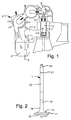
- An exhaust valve 1 is viewed in Fig. 1 in an open position allowing intake air to be supplied from a turbocharger 2 to a scavenge air receiver 3 via a scavenge air cooler 4 and a water mist catcher 5.
- the intake and scavenge air flows from the scavenge air receiver through a row of scavenge air ports 6 in the lower end of a cylinder 7 and upwards through the cylinder in a swirling motion and up towards the upper portion of the cylinder, while at the same time pressing out hot combustion gasses via the open exhaust valve and into the exhaust gas receiver 8.
- the flow of hot combustion gasses past the valve seats of the exhaust valve can occur at high gas speeds, in particular when the valve opens and closes.
- the exhaust valve 1 is mounted in an exhaust valve housing 9 that is fixed to a cylinder cover 10 at the top of the cylinder. In the closed position of the exhaust valve, a valve seat area 11 on the upper side of a valve disc 12 abuts a corresponding valve seat on a stationary part 13, also called the bottom piece, of the valve housing.
- the valve disc has a first side 14 facing upwards towards exhaust channel 15 and a second side 16 facing downwards to combustion chamber 17 in the cylinder 7.
- a valve stem 18 extends centrally from the first side 14 and has a portion 19 for mounting of valve rotator wings, a bearing area 20 for positioning in a stationary valve guide in the valve housing, a groove 21 for mounting of an air spring piston or a spring end support, and an upper end area 22 for mounting at an actuator piston in a hydraulic valve actuator.
- the upper end of the stem may alternatively be actuated by a cam in a traditional manner.
- the stationary part 13 can be cooled by water.
- the stem 18 In the mounted position of the exhaust valve, the stem 18 extends upwards from the valve disc and passes the exhaust channel and continues upwards through the valve guide and up into an exhaust valve actuator.
- a piston of a pneumatic spring is mounted to the outside of the stem.
- a hydraulic actuator piston at the top of the stem can activate the exhaust valve for downward movement, and the pneumatic spring acts in the opposite direction and closes the exhaust valve when the pressure in the hydraulic actuator is relieved.
- the embodiment illustrated in Fig. 2 is an exhaust valve for an engine of one of the types ME or MC of applicant's brand.
- the exhaust valve could also be mechanically actuated in well-known manner, and a mechanical return spring could also be used.
- the portion of the stem located in the exhaust channel is provided with oblique fins extending out radially from the stem. These fins cause the exhaust valve to rotate some degrees in the circumferential direction when the exhaust gas is flowing out. In another embodiment the stem does not have such fins.
- the exhaust valve can be for a four-stroke internal combustion engine, or it can be for a two-stroke internal combustion engine, preferably a large two-stroke crosshead engine, which may have cylinder diameters ranging from 250 to 1100 mm.
- the outer diameter of the valve disc 12 is in the range from 100 mm to 600 mm, depending on the cylinder bore, when the valve is for such large two-stroke engines.
- the internal combustion engine utilizing the exhaust valve spindles may be of the make MAN Diesel & Turbo, such as of the type MC or ME, or may be of the make Wärtsilä or Sulzer Diesel, such as of the type RTA of RTA-flex, or may be of the make Mitsubishi.
- the outer diameter of the valve disc 12 is typically in the range from 50 mm to 300 mm.
- Valve seat area 11 is in general annular and conical and located next to an outer end portion of the valve disc.
- the valve seat area can be of the same alloy as the remainder of the exhaust valve, or it can be of a different alloy deposited in a groove 23 on a base body 24, as illustrated in Fig. 3 .
- groove 23 is filled with six weld seams 25.
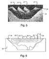
- After rolling the cross sectional shape of the valve seat area is as depicted in Fig. 5 .
- the rolling presses material sideways of the roll so that ridges 27 are formed.
- the rolling depth 28 below the outer surface of the raw seat represents excess material that must be removed after rolling, such as by machining on a lathe.
- a reference sample was manufactured of an Inconel 718 valve seat alloy welded onto a stainless steel base body. Rolling was performed as illustrated in Fig. 4 with the results as presented in Fig. 5 . The excess material was removed by turning on a lathe. The valve disc was subjected to age hardening. The hardness of the resulting valve seat area is illustrated in Fig. 6 . The following hardness values have been achieved: areas marked 29 hardness 575 HV; areas marked 30 hardness 550 HV; areas marked 31 hardness 525 HV; areas marked 32 hardness 500 HV; areas marked 33 hardness 475 HV; and areas marked 34 hardness 450 HV.
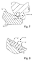
- FIG. 7 An example of a stationary valve housing part 13 is illustrated in Fig. 7 .
- a section is shown through an outer area of the exhaust valve disc and a stationary valve housing part having seat surfaces 35, 36 abutting the valve seat area 11 when the exhaust valve is in closed position.
- the stationary valve housing part can have a single seat surface substantially covering the outer surface of the valve seat area.
- the valve disc 12 with a raw seat area is provided.
- the raw seat area has two annular protrusions 37 separated by an intermediate annular area 38.
- the annular protrusions 37 have less width than the intermediate annular area 38.
- the two annular protrusions 37 are then plastically deformed by rolling with a rolling tool 39 as illustrated in Fig. 9 .
- the rolling tool has a roll 40 which is cylindrically shaped and mounted in the tool so that the roll can rotate about central axis 41, which extends in parallel with the cylindrical outer surface of the roll. During rolling the rolling tool presses the roll against the seat raw area with sufficient force to cause plastic deformation of the annular protrusions.
- a load of 5 to 10 t on the roll may be suitable for generating the required force for rolling a seat area on a valve disc having an outer diameter of about 0.35 m.
- the rolling tool is positioned with central axis 41 in parallel with the outer surface of the valve seat area 11, and the valve disc is fixed on a rotating table.
- the rotating table rotates the valve disc about the longitudinal axis of the valve and thus the roll 40 rolls on the valve seat area.
- the rolling tool may also be embodied with two rolls both rotating about axis 41, and the rolling tool may then be positioned so that the one roll is pressing only on one of the annular protrusions, and the other roll is pressing only on the other of the annular protrusions.
- annular protrusions After completion of the rolling the annular protrusions have been plastically deformed into the valve seat area so that the outer surface of the valve seat area 11 follows a conical surface.
- the individual annular protrusion 37 has thus been deformed into a second annular portion 42 of the valve seat area, and a first annular portion 43 is located in between the second annular portions 42.
- the first annular portion 43 has lower hardness than the two second annular portions 42 because the first annular portion has not been subjected to the same amount of plastic deformation as the second annular portions.
- Fig. 11 The hardness distribution in the valve seat area is depicted in Fig. 11 for an example of a valve disc having an outer diameter of 0.35 m and a base body of stainless steel (SNCrW stainless steel) and a valve seat area of alloy Inconel 718 (Inconel is a trade mark of Special Metals Corporation) of 53% nickel + cobalt, 19% chromium, 18% iron, 5.3% niobium, 3% molybdenum, 0.9% titanium, 0.5% aluminium, less than 1% cobalt, less than 0.08% carbon, less than 0.35% manganese, less than 0.35% silicon, less than 0.015% phosphorus, less than 0.015% sulfur, less than 0.006% boron, less than 0.3% copper, and unavoidable impurities.
- alloy Inconel 718 Inconel is a trade mark of Special Metals Corporation
- the rolling was performed with a loading of 10 t on the rolling tool.
- the valve disc was subjected to an aging heat treatment at 720°C for six hours followed by 620°C for six hours. As an alternative the aging heat treatment may be performed for 10 hours at 730°C.
- a piece was cut from the valve seat area and the hardness was measured. The hardness distribution is illustrated in Fig.
- HV HV 11
- Table 1 Reference numeral Vickers hardness range HV 44 450 to 588 45 429 to 450 46 408 to 450 47 387 to 408 48 366 to 387 49 345 to 366 50 325 to 345 51 304 to 325 52 283 to 304 53 262 to 283 54 241 to 262 55 220 to 241 56 200 to 220 57 below 200
- the area of highest hardness of 588 HV was located at the middle of the second annular portion at about 0.3 mm below the outer surface.
- the outermost material is removed to a depth of 0.2 mm as indicated by the broken line in Fig. 11 .
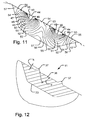
- the annular protrusions 37 in the raw seat area on valve disc 12 may have other configurations, such as the one illustrated in Fig. 12 where the central portion of the protrusion 37 is flat. Hardness distributions in the valve seat area have been found for some different embodiments of the protrusions.
- the height h of the protrusion and the angle ⁇ for the sides of the protrusion are illustrated in Fig. 12 .
- the protrusion having a height of 0.8 mm provided a hardness of 504 HV and a slightly lower hardness of about 450 HV at the middle of the surface of the second annular portion.
- the protrusion having a height of 1.0 mm provided a hardness of 502 HV and a slightly lower hardness of about 475 HV at the middle of the surface of the second annular portion.
- the protrusion having a height of 1.0 mm provided a hardness of 575 HV and a slightly lower hardness of about 450 HV at the middle of the surface of the second annular portion.
- the protrusion having a height of 1.5 mm provided a hardness of 599 HV and a quite even hardness of about 500 HV across the width of the surface of the second annular portion.
- the protrusion having a height of 2.0 mm provided a hardness of 619 HV and a quite even hardness of about 520 HV across the width of the surface of the second annular portion.
- the hardness of the first annular portion was much lower than the hardness of the second annular portions.
- the hardness of the first annular portion was generally in the range from 200 HV to 300 HV, and in most examples the hardness of the first annular portion was generally in the range from 200 HV to 260 HV.
- the first annular portion is thus providing the valve seat area with a significantly increased ductility. If the stationary valve housing part has two seat surfaces 35, 36 the second annular portions 37 are preferably located so as to abut seat surfaces 35, 36 when the valve is in closed position.
- the second annular portions 37 are preferably located so as to both abut this seat surface when the valve is in closed position. It is preferred that the average hardness at the valve seat surface at the middle of the first annular portion is at least 80 HV lower than the average hardness at the middle of the surface of at least one of the second annular portions. This average hardness is found by measuring the hardness at least at five positions distributed along the circle located at the middle of the surface of the portions, and then finding the average of the measured values. The difference in aver-age hardness may be only 50 HV or may be larger than 80 HV, such as 150 HV, 250 HV or 300 HV.
- the hardness of the first annular portion was generally in the range from 200 HV to 260 HV, and the hardness of the second annular portions was generally higher than 460 HV, which makes the difference at least 200 HV.
- the valve seat area can be of a nickel-based alloy, which alloy stated in percent-by-weight and apart from common impurities and inevitable residual amounts of deoxidizing components comprises at least from 34.0 to 44.0% Cr, an aggregate amount of Nb and Ta in the range from at least 2.8 to 6.1%, from 0.3 to 2.0% Ti, a balance of Ni, and optionally one or more of the components at the most 0.2% Al, at the most 0.04% B, at the most 0.8% Fe, at the most 0.04% C, and at the most 0.4% Si.
- valve seat area can be of a nickel-based alloy comprising at least the components 10-25% Cr, 5-25% Co, 2-23% Ta, a balance of Ni, and optionally one or more of the components up to 10% Mo+W, up to 11% Nb, up to 4% Ti, up to 3% Al, up to 0.3% C, up to 1% Si, up to 0.015% S, up to 5% Fe, and up to 3% Mn.
- valve seat area can be of a nickel-based alloy comprising at least the components 20-23% Cr, 8-10% Mo, 3.15-4.15% Ta+Nb, a balance of at least 58% Ni, and optionally one or more of the components up to 5% Fe, up to 0.1% C, up to 0.5% Mn, up to 0.5% Si, up to 0.4% Al, up to 0.4% Ti, up to 1.0% Co, up to 0.015% Si, and up to 0.015% P.
- the valve seat area can be of a nickel-based alloy comprising at least the components 27-30% Cr, 7-11% Fe, up to 0.05% C, optionally small amounts of Mg, Co, Si and a balance of at least 58% Ni.
- valve seat area can be of an alloy comprising at least the components 10-25% Cr, 3-12% Nb and/or Ta, 5-25% Fe, and a balance of nickel and/or cobalt.
- valve seat area can be of an alloy comprising at least the components 0.04-0.08% C, 46-49% Cr, 0.3-0.5% Ti, and a balance of Ni.
- the entire valve disc, and thus also the valve seat area can be of the alloy Nimonic 80A (Nimonic is a trade mark of Special Metals Corporation) comprising at least the components 18-21% Cr, 1.8-2.7% Ti, 1.0-1.8% Al, at the most 3.0% Fe, at the most 2.0% Co, and as balance Ni.
- valve disc comprises a base material of stainless steel it can be a stainless steel, such as an alloy having 0.25% C, 1.4% Si, 1.3% Mn, 20% Cr, 9% Ni, 3% W, and the balance Fe.
- Other stainless steels can also be used and are well-known in the art of exhaust valves.
- valve disc 12 comprises at its second side a layer of a hot corrosion resistant material, such as a layer of a nickel-based alloy comprising at least the components 20-23% Cr, 8-10% Mo, 3.15-4.15% Ta+Nb, a balance of at least 58% Ni, and optionally one or more of the components up to 5% Fe, up to 0.1% C, up to 0.5% Mn, up to 0.5% Si, up to 0.4% Al, up to 0.4% Ti, up to 1.0% Co, up to 0.015% Si, and up to 0.015% P.
- a hot corrosion resistant material such as a layer of a nickel-based alloy comprising at least the components 20-23% Cr, 8-10% Mo, 3.15-4.15% Ta+Nb, a balance of at least 58% Ni, and optionally one or more of the components up to 5% Fe, up to 0.1% C, up to 0.5% Mn, up to 0.5% Si, up to 0.4% Al, up to 0.4% Ti, up to 1.0% Co, up to 0.015% Si, and up to 0.01
- valve seat area is of an alloy different from the alloy of the base body of the exhaust valve
- the valve seat area can be deposited in a groove 23 on a base body 24 by welding with several weld seams.
- the welding can be performed by plasma welding, laser welding, gas metal arc welding or gas tungsten arc welding.
- the valve seat area can alternatively be deposited by processes like cold-spraying or HIP. In embodiments having a layer of a hot corrosion material on the second side of the valve disc, the mentioned processes can likewise be applied to deposit the layer.
Landscapes
- Chemical & Material Sciences (AREA)
- Engineering & Computer Science (AREA)
- Mechanical Engineering (AREA)
- Materials Engineering (AREA)
- Metallurgy (AREA)
- Organic Chemistry (AREA)
- Physics & Mathematics (AREA)
- Thermal Sciences (AREA)
- Crystallography & Structural Chemistry (AREA)
- General Engineering & Computer Science (AREA)
- Lift Valve (AREA)
- Check Valves (AREA)
Applications Claiming Priority (1)
| Application Number | Priority Date | Filing Date | Title |
|---|---|---|---|
| DK201470184A DK177960B1 (en) | 2014-04-08 | 2014-04-08 | An exhaust valve for an internal combustion engine |
Publications (2)
| Publication Number | Publication Date |
|---|---|
| EP2933445A1 EP2933445A1 (en) | 2015-10-21 |
| EP2933445B1 true EP2933445B1 (en) | 2016-10-26 |
Family
ID=52430733
Family Applications (1)
| Application Number | Title | Priority Date | Filing Date |
|---|---|---|---|
| EP15162032.5A Not-in-force EP2933445B1 (en) | 2014-04-08 | 2015-03-31 | An exhaust valve for an internal combustion engine, and a method of strengthening an annular valve seat area in an exhaust valve |
Country Status (7)
| Country | Link |
|---|---|
| US (2) | US20150285109A1 (enExample) |
| EP (1) | EP2933445B1 (enExample) |
| JP (1) | JP6158245B2 (enExample) |
| KR (1) | KR101663494B1 (enExample) |
| CN (1) | CN104975899B (enExample) |
| DK (1) | DK177960B1 (enExample) |
| SG (1) | SG10201502657SA (enExample) |
Families Citing this family (25)
| Publication number | Priority date | Publication date | Assignee | Title |
|---|---|---|---|---|
| CN104853823B (zh) * | 2014-08-27 | 2016-05-25 | 日锻汽门株式会社 | 提升阀的制造方法 |
| WO2018210416A1 (en) * | 2017-05-17 | 2018-11-22 | Federal-Mogul Valvetrain Gmbh | Poppet valve and method for production thereof |
| JP6926231B2 (ja) * | 2017-05-17 | 2021-08-25 | フェデラル−モーグル バルブトレイン ゲーエムベーハーFederal−Mogul Valvetrain Gmbh | ポペットバルブおよびその製造方法 |
| US11353117B1 (en) | 2020-01-17 | 2022-06-07 | Vulcan Industrial Holdings, LLC | Valve seat insert system and method |
| GB202004947D0 (en) * | 2020-04-03 | 2020-05-20 | Rolls Royce Plc | Joining component bodies |
| US12049889B2 (en) | 2020-06-30 | 2024-07-30 | Vulcan Industrial Holdings, LLC | Packing bore wear sleeve retainer system |
| US11421679B1 (en) | 2020-06-30 | 2022-08-23 | Vulcan Industrial Holdings, LLC | Packing assembly with threaded sleeve for interaction with an installation tool |
| US11421680B1 (en) | 2020-06-30 | 2022-08-23 | Vulcan Industrial Holdings, LLC | Packing bore wear sleeve retainer system |
| US11384756B1 (en) | 2020-08-19 | 2022-07-12 | Vulcan Industrial Holdings, LLC | Composite valve seat system and method |
| USD980876S1 (en) | 2020-08-21 | 2023-03-14 | Vulcan Industrial Holdings, LLC | Fluid end for a pumping system |
| USD997992S1 (en) | 2020-08-21 | 2023-09-05 | Vulcan Industrial Holdings, LLC | Fluid end for a pumping system |
| USD986928S1 (en) | 2020-08-21 | 2023-05-23 | Vulcan Industrial Holdings, LLC | Fluid end for a pumping system |
| US12366245B1 (en) | 2020-08-27 | 2025-07-22 | Vulcan Industrial Holdings, LLC | Connecting rod assembly for reciprocating pump |
| CN116324133B (zh) * | 2020-10-21 | 2025-08-08 | 日产自动车株式会社 | 气缸盖毛坯和气缸盖的制造方法 |
| US11391374B1 (en) | 2021-01-14 | 2022-07-19 | Vulcan Industrial Holdings, LLC | Dual ring stuffing box |
| US12055221B2 (en) | 2021-01-14 | 2024-08-06 | Vulcan Industrial Holdings, LLC | Dual ring stuffing box |
| US12292120B1 (en) | 2021-02-23 | 2025-05-06 | Vulcan Industrial Holdings, LLC | System and method for valve assembly |
| US11846356B1 (en) | 2021-08-18 | 2023-12-19 | Vulcan Industrial Holdings, LLC | Self-locking plug |
| US12140240B1 (en) | 2022-01-19 | 2024-11-12 | Vulcan Industrial Holdings, LLC | Gradient material structures and methods of forming the same |
| US12297922B1 (en) | 2022-03-04 | 2025-05-13 | Vulcan Industrial Holdings, LLC | Valve seat with embedded structure and related methods |
| US11434900B1 (en) | 2022-04-25 | 2022-09-06 | Vulcan Industrial Holdings, LLC | Spring controlling valve |
| US11920684B1 (en) | 2022-05-17 | 2024-03-05 | Vulcan Industrial Holdings, LLC | Mechanically or hybrid mounted valve seat |
| USD1061623S1 (en) | 2022-08-03 | 2025-02-11 | Vulcan Industrial Holdings, LLC | Fluid end for a pumping system |
| CN115962025B (zh) * | 2022-12-19 | 2025-11-18 | 南京中远海运船舶设备配件有限公司 | 一种大型船舶用低速机排气阀阀盘 |
| US12292121B2 (en) | 2023-08-10 | 2025-05-06 | Vulcan Industrial Holdings, LLC | Valve member including cavity, and related assemblies, systems, and methods |
Family Cites Families (31)
| Publication number | Priority date | Publication date | Assignee | Title |
|---|---|---|---|---|
| US2392152A (en) * | 1942-01-24 | 1946-01-01 | Thompson Prod Inc | Method of cold working hollow headed articles |
| FR1531687A (fr) * | 1967-05-25 | 1968-07-05 | Semt | Perfectionnements aux soupapes |
| US3649380A (en) * | 1969-04-14 | 1972-03-14 | Trw Inc | Method of manufacturing hard faced exhaust valves |
| US4122817A (en) * | 1975-05-01 | 1978-10-31 | Trw Inc. | Internal combustion valve having an iron based hard-facing alloy contact surface |
| US4075999A (en) * | 1975-06-09 | 1978-02-28 | Eaton Corporation | Hard facing alloy for engine valves and the like |
| US4161414A (en) * | 1977-02-10 | 1979-07-17 | Saint Prix Robert | Process for fabricating fluid-control members for internal-combustion engines and the like |
| US4530322A (en) * | 1980-10-31 | 1985-07-23 | Nippon Kokan Kabushiki Kaisha | Exhaust valve for diesel engine and production thereof |
| JPS60122207A (ja) * | 1983-12-05 | 1985-06-29 | Mitsui Eng & Shipbuild Co Ltd | 内燃機関の排気部構造 |
| JPS60122206A (ja) * | 1983-12-06 | 1985-06-29 | Mitsui Eng & Shipbuild Co Ltd | 内燃機関の弁 |
| DE3517077C1 (de) | 1985-05-11 | 1986-11-06 | M.A.N.- B & W Diesel GmbH, 8900 Augsburg | Verfahren zum Panzern der Ventilsitzflaeche eines thermisch und mechanisch hoch belastbaren sowie gegen Korrosion geschuetzten Gaswechselventils fuer eine schweroelbetriebene Brennkraftmaschine |
| EP0521821B1 (de) * | 1991-07-04 | 1996-07-31 | New Sulzer Diesel Ag | Auslassventil einer Diesel-Brennkraftmaschine und Verfahren zum Herstellen des Ventils |
| US5233366A (en) * | 1992-05-26 | 1993-08-03 | Xerox Corporation | Half-tone printing with thermal ink jet using random spot distribution in one dimension |
| JPH09256821A (ja) * | 1996-03-19 | 1997-09-30 | Aisan Ind Co Ltd | エンジンバルブ |
| DK173136B1 (da) * | 1996-05-15 | 2000-02-07 | Man B & W Diesel As | Bevægeligt vægelement i form af en udstødsventilspindel eller et stempel i en forbrændingsmotor. |
| DK173348B1 (da) * | 1996-06-07 | 2000-08-07 | Man B & W Diesel As | Udstødsventil til en forbrændingsmotor |
| DK173337B1 (da) * | 1996-06-07 | 2000-07-31 | Man B & W Diesel As | Udstødsventil til en forbrændingsmotor |
| EP0859131A1 (en) * | 1997-02-14 | 1998-08-19 | Fuji Oozx Inc. | Poppet valve and method of making it |
| CN1191950A (zh) * | 1997-02-25 | 1998-09-02 | 富士乌兹克斯株式会社 | 提升阀及其制造方法 |
| JPH11270320A (ja) * | 1998-03-20 | 1999-10-05 | Nittan Valve Co Ltd | 内燃機関用バルブの製法及びその製法により成形されたバルブ |
| EP1152127B1 (en) * | 1999-02-12 | 2011-09-07 | Nittan Valve Co., Ltd. | Hollow poppet valve and its manufacturing method |
| US6295731B1 (en) * | 1999-10-20 | 2001-10-02 | Fuji Oozx Inc. | Method of hardening a valve face of a poppet valve |
| JP3978004B2 (ja) * | 2000-08-28 | 2007-09-19 | 株式会社日立製作所 | 耐蝕・耐摩耗性合金とそれを用いた機器 |
| US6385847B1 (en) | 2000-09-13 | 2002-05-14 | Eaton Corporation | Seat faced engine valves and method of making seat faced engine valves |
| EP1950384B1 (en) * | 2005-11-15 | 2014-03-19 | Nittan Valve Co., Ltd. | Coolant-containing hollow poppet valve and process for producing the same |
| US7562647B2 (en) * | 2006-03-29 | 2009-07-21 | High Performance Coatings, Inc. | Inlet valve having high temperature coating and internal combustion engines incorporating same |
| DE102008018875A1 (de) * | 2008-04-14 | 2009-10-15 | Märkisches Werk GmbH | Auslassventil an einem Hubkolbenmotor |
| DE102008054266A1 (de) | 2008-10-31 | 2010-05-06 | Mahle International Gmbh | Beweglicher, heißen Gasen ausgesetzter Verschlusskörper eines Ventiles |
| US8757124B2 (en) * | 2009-01-23 | 2014-06-24 | Man Diesel, Filial Af Man Diesel Se, Tyskland | Movable wall member in form of an exhaust valve spindle or a piston for internal combustion engine, and a method of manufacturing such a member |
| JP2011038438A (ja) * | 2009-08-07 | 2011-02-24 | Yamaha Motor Co Ltd | 吸気バルブと、これを備えた内燃機関及び輸送機器 |
| EP2740908B1 (en) * | 2012-06-14 | 2016-10-26 | Nittan Valve Co., Ltd. | Method of forming poppet valve faces and poppet valves having faces formed by this method |
| DK177487B1 (en) * | 2012-07-06 | 2013-07-15 | Man Diesel & Turbo Deutschland | An exhaust valve spindle for an exhaust valve in an internal combustion engine |
-
2014
- 2014-04-08 DK DK201470184A patent/DK177960B1/da not_active IP Right Cessation
-
2015
- 2015-03-16 KR KR1020150036129A patent/KR101663494B1/ko not_active Expired - Fee Related
- 2015-03-31 EP EP15162032.5A patent/EP2933445B1/en not_active Not-in-force
- 2015-04-03 US US14/678,057 patent/US20150285109A1/en not_active Abandoned
- 2015-04-06 SG SG10201502657SA patent/SG10201502657SA/en unknown
- 2015-04-07 JP JP2015078547A patent/JP6158245B2/ja active Active
- 2015-04-08 CN CN201510163235.7A patent/CN104975899B/zh not_active Expired - Fee Related
-
2018
- 2018-07-09 US US16/030,252 patent/US10443456B2/en active Active
Also Published As
| Publication number | Publication date |
|---|---|
| EP2933445A1 (en) | 2015-10-21 |
| KR101663494B1 (ko) | 2016-10-07 |
| SG10201502657SA (en) | 2015-11-27 |
| CN104975899B (zh) | 2018-07-24 |
| JP6158245B2 (ja) | 2017-07-05 |
| US20180313238A1 (en) | 2018-11-01 |
| US20150285109A1 (en) | 2015-10-08 |
| US10443456B2 (en) | 2019-10-15 |
| JP2015212543A (ja) | 2015-11-26 |
| KR20150116770A (ko) | 2015-10-16 |
| CN104975899A (zh) | 2015-10-14 |
| DK177960B1 (en) | 2015-02-02 |
Similar Documents
| Publication | Publication Date | Title |
|---|---|---|
| US10443456B2 (en) | Exhaust valve for an internal combustion engine, and a method of strengthening an annular valve seat area in an exhaust valve | |
| EP2682571B1 (en) | An exhaust valve spindle for an exhaust valve in an internal combustion engine and a method of manufacturing the exhaust valve spindle | |
| EP1462621B1 (en) | Composite lightweight engine poppet valve | |
| US9597725B2 (en) | Hot forging die | |
| EP0901565B1 (en) | An exhaust valve for an internal combustion engine | |
| US6173702B1 (en) | Movable wall member in the form of an exhaust valve spindle or a piston in an internal combustion engine | |
| US8757124B2 (en) | Movable wall member in form of an exhaust valve spindle or a piston for internal combustion engine, and a method of manufacturing such a member | |
| JP6011098B2 (ja) | 大型船舶用エンジン排気バルブの製造方法 | |
| CN101548120B (zh) | 阀装置 | |
| EP1188905B2 (en) | Seat faced engine valves and method of making the same | |
| US9404400B2 (en) | Cylinder head with valve seat and method for the production thereof | |
| WO2014014069A1 (ja) | 大型船舶用エンジン排気バルブの製造方法 | |
| KR20240133041A (ko) | 선박 엔진용 배기밸브 스핀들의 제조방법 | |
| US20250257435A1 (en) | MOLYBDENUM-Based Alloy | |
| US12209516B2 (en) | Armored poppet valve and method for the production thereof | |
| Beddoes | Valve materials and design | |
| Kusmierczak et al. | Comparison of semifinished product influence on surface degradation of forging rolls | |
| HK1152350B (en) | Cobalt-rich wear resistant alloy and method of making and use thereof | |
| HK1152350A1 (en) | Cobalt-rich wear resistant alloy and method of making and use thereof |
Legal Events
| Date | Code | Title | Description |
|---|---|---|---|
| PUAI | Public reference made under article 153(3) epc to a published international application that has entered the european phase |
Free format text: ORIGINAL CODE: 0009012 |
|
| 17P | Request for examination filed |
Effective date: 20150331 |
|
| AK | Designated contracting states |
Kind code of ref document: A1 Designated state(s): AL AT BE BG CH CY CZ DE DK EE ES FI FR GB GR HR HU IE IS IT LI LT LU LV MC MK MT NL NO PL PT RO RS SE SI SK SM TR |
|
| AX | Request for extension of the european patent |
Extension state: BA ME |
|
| GRAP | Despatch of communication of intention to grant a patent |
Free format text: ORIGINAL CODE: EPIDOSNIGR1 |
|
| RIC1 | Information provided on ipc code assigned before grant |
Ipc: F01L 3/02 20060101AFI20160517BHEP Ipc: B21K 1/22 20060101ALI20160517BHEP |
|
| INTG | Intention to grant announced |
Effective date: 20160603 |
|
| GRAS | Grant fee paid |
Free format text: ORIGINAL CODE: EPIDOSNIGR3 |
|
| GRAA | (expected) grant |
Free format text: ORIGINAL CODE: 0009210 |
|
| AK | Designated contracting states |
Kind code of ref document: B1 Designated state(s): AL AT BE BG CH CY CZ DE DK EE ES FI FR GB GR HR HU IE IS IT LI LT LU LV MC MK MT NL NO PL PT RO RS SE SI SK SM TR |
|
| REG | Reference to a national code |
Ref country code: GB Ref legal event code: FG4D |
|
| REG | Reference to a national code |
Ref country code: CH Ref legal event code: EP |
|
| REG | Reference to a national code |
Ref country code: AT Ref legal event code: REF Ref document number: 840195 Country of ref document: AT Kind code of ref document: T Effective date: 20161115 |
|
| REG | Reference to a national code |
Ref country code: IE Ref legal event code: FG4D |
|
| REG | Reference to a national code |
Ref country code: DE Ref legal event code: R096 Ref document number: 602015000538 Country of ref document: DE |
|
| REG | Reference to a national code |
Ref country code: SE Ref legal event code: TRGR |
|
| REG | Reference to a national code |
Ref country code: NL Ref legal event code: FP |
|
| REG | Reference to a national code |
Ref country code: LT Ref legal event code: MG4D |
|
| PG25 | Lapsed in a contracting state [announced via postgrant information from national office to epo] |
Ref country code: LV Free format text: LAPSE BECAUSE OF FAILURE TO SUBMIT A TRANSLATION OF THE DESCRIPTION OR TO PAY THE FEE WITHIN THE PRESCRIBED TIME-LIMIT Effective date: 20161026 |
|
| REG | Reference to a national code |
Ref country code: FR Ref legal event code: PLFP Year of fee payment: 3 |
|
| PG25 | Lapsed in a contracting state [announced via postgrant information from national office to epo] |
Ref country code: LT Free format text: LAPSE BECAUSE OF FAILURE TO SUBMIT A TRANSLATION OF THE DESCRIPTION OR TO PAY THE FEE WITHIN THE PRESCRIBED TIME-LIMIT Effective date: 20161026 Ref country code: NO Free format text: LAPSE BECAUSE OF FAILURE TO SUBMIT A TRANSLATION OF THE DESCRIPTION OR TO PAY THE FEE WITHIN THE PRESCRIBED TIME-LIMIT Effective date: 20170126 Ref country code: GR Free format text: LAPSE BECAUSE OF FAILURE TO SUBMIT A TRANSLATION OF THE DESCRIPTION OR TO PAY THE FEE WITHIN THE PRESCRIBED TIME-LIMIT Effective date: 20170127 |
|
| PG25 | Lapsed in a contracting state [announced via postgrant information from national office to epo] |
Ref country code: PT Free format text: LAPSE BECAUSE OF FAILURE TO SUBMIT A TRANSLATION OF THE DESCRIPTION OR TO PAY THE FEE WITHIN THE PRESCRIBED TIME-LIMIT Effective date: 20170227 Ref country code: PL Free format text: LAPSE BECAUSE OF FAILURE TO SUBMIT A TRANSLATION OF THE DESCRIPTION OR TO PAY THE FEE WITHIN THE PRESCRIBED TIME-LIMIT Effective date: 20161026 Ref country code: BE Free format text: LAPSE BECAUSE OF FAILURE TO SUBMIT A TRANSLATION OF THE DESCRIPTION OR TO PAY THE FEE WITHIN THE PRESCRIBED TIME-LIMIT Effective date: 20161026 Ref country code: ES Free format text: LAPSE BECAUSE OF FAILURE TO SUBMIT A TRANSLATION OF THE DESCRIPTION OR TO PAY THE FEE WITHIN THE PRESCRIBED TIME-LIMIT Effective date: 20161026 Ref country code: IS Free format text: LAPSE BECAUSE OF FAILURE TO SUBMIT A TRANSLATION OF THE DESCRIPTION OR TO PAY THE FEE WITHIN THE PRESCRIBED TIME-LIMIT Effective date: 20170226 Ref country code: HR Free format text: LAPSE BECAUSE OF FAILURE TO SUBMIT A TRANSLATION OF THE DESCRIPTION OR TO PAY THE FEE WITHIN THE PRESCRIBED TIME-LIMIT Effective date: 20161026 Ref country code: RS Free format text: LAPSE BECAUSE OF FAILURE TO SUBMIT A TRANSLATION OF THE DESCRIPTION OR TO PAY THE FEE WITHIN THE PRESCRIBED TIME-LIMIT Effective date: 20161026 |
|
| REG | Reference to a national code |
Ref country code: DE Ref legal event code: R097 Ref document number: 602015000538 Country of ref document: DE |
|
| PG25 | Lapsed in a contracting state [announced via postgrant information from national office to epo] |
Ref country code: CZ Free format text: LAPSE BECAUSE OF FAILURE TO SUBMIT A TRANSLATION OF THE DESCRIPTION OR TO PAY THE FEE WITHIN THE PRESCRIBED TIME-LIMIT Effective date: 20161026 Ref country code: DK Free format text: LAPSE BECAUSE OF FAILURE TO SUBMIT A TRANSLATION OF THE DESCRIPTION OR TO PAY THE FEE WITHIN THE PRESCRIBED TIME-LIMIT Effective date: 20161026 Ref country code: EE Free format text: LAPSE BECAUSE OF FAILURE TO SUBMIT A TRANSLATION OF THE DESCRIPTION OR TO PAY THE FEE WITHIN THE PRESCRIBED TIME-LIMIT Effective date: 20161026 Ref country code: RO Free format text: LAPSE BECAUSE OF FAILURE TO SUBMIT A TRANSLATION OF THE DESCRIPTION OR TO PAY THE FEE WITHIN THE PRESCRIBED TIME-LIMIT Effective date: 20161026 Ref country code: SK Free format text: LAPSE BECAUSE OF FAILURE TO SUBMIT A TRANSLATION OF THE DESCRIPTION OR TO PAY THE FEE WITHIN THE PRESCRIBED TIME-LIMIT Effective date: 20161026 |
|
| PG25 | Lapsed in a contracting state [announced via postgrant information from national office to epo] |
Ref country code: IT Free format text: LAPSE BECAUSE OF FAILURE TO SUBMIT A TRANSLATION OF THE DESCRIPTION OR TO PAY THE FEE WITHIN THE PRESCRIBED TIME-LIMIT Effective date: 20161026 Ref country code: BG Free format text: LAPSE BECAUSE OF FAILURE TO SUBMIT A TRANSLATION OF THE DESCRIPTION OR TO PAY THE FEE WITHIN THE PRESCRIBED TIME-LIMIT Effective date: 20170126 Ref country code: SM Free format text: LAPSE BECAUSE OF FAILURE TO SUBMIT A TRANSLATION OF THE DESCRIPTION OR TO PAY THE FEE WITHIN THE PRESCRIBED TIME-LIMIT Effective date: 20161026 |
|
| PLBE | No opposition filed within time limit |
Free format text: ORIGINAL CODE: 0009261 |
|
| STAA | Information on the status of an ep patent application or granted ep patent |
Free format text: STATUS: NO OPPOSITION FILED WITHIN TIME LIMIT |
|
| 26N | No opposition filed |
Effective date: 20170727 |
|
| PG25 | Lapsed in a contracting state [announced via postgrant information from national office to epo] |
Ref country code: SI Free format text: LAPSE BECAUSE OF FAILURE TO SUBMIT A TRANSLATION OF THE DESCRIPTION OR TO PAY THE FEE WITHIN THE PRESCRIBED TIME-LIMIT Effective date: 20161026 Ref country code: MC Free format text: LAPSE BECAUSE OF FAILURE TO SUBMIT A TRANSLATION OF THE DESCRIPTION OR TO PAY THE FEE WITHIN THE PRESCRIBED TIME-LIMIT Effective date: 20161026 |
|
| REG | Reference to a national code |
Ref country code: IE Ref legal event code: MM4A |
|
| PG25 | Lapsed in a contracting state [announced via postgrant information from national office to epo] |
Ref country code: LU Free format text: LAPSE BECAUSE OF NON-PAYMENT OF DUE FEES Effective date: 20170331 |
|
| PG25 | Lapsed in a contracting state [announced via postgrant information from national office to epo] |
Ref country code: IE Free format text: LAPSE BECAUSE OF NON-PAYMENT OF DUE FEES Effective date: 20170331 |
|
| REG | Reference to a national code |
Ref country code: FR Ref legal event code: PLFP Year of fee payment: 4 |
|
| PG25 | Lapsed in a contracting state [announced via postgrant information from national office to epo] |
Ref country code: MT Free format text: LAPSE BECAUSE OF NON-PAYMENT OF DUE FEES Effective date: 20170331 |
|
| REG | Reference to a national code |
Ref country code: CH Ref legal event code: PL |
|
| PG25 | Lapsed in a contracting state [announced via postgrant information from national office to epo] |
Ref country code: LI Free format text: LAPSE BECAUSE OF NON-PAYMENT OF DUE FEES Effective date: 20180331 Ref country code: CH Free format text: LAPSE BECAUSE OF NON-PAYMENT OF DUE FEES Effective date: 20180331 |
|
| PG25 | Lapsed in a contracting state [announced via postgrant information from national office to epo] |
Ref country code: HU Free format text: LAPSE BECAUSE OF FAILURE TO SUBMIT A TRANSLATION OF THE DESCRIPTION OR TO PAY THE FEE WITHIN THE PRESCRIBED TIME-LIMIT; INVALID AB INITIO Effective date: 20150331 |
|
| REG | Reference to a national code |
Ref country code: AT Ref legal event code: UEP Ref document number: 840195 Country of ref document: AT Kind code of ref document: T Effective date: 20161026 |
|
| PG25 | Lapsed in a contracting state [announced via postgrant information from national office to epo] |
Ref country code: CY Free format text: LAPSE BECAUSE OF FAILURE TO SUBMIT A TRANSLATION OF THE DESCRIPTION OR TO PAY THE FEE WITHIN THE PRESCRIBED TIME-LIMIT Effective date: 20161026 |
|
| PG25 | Lapsed in a contracting state [announced via postgrant information from national office to epo] |
Ref country code: MK Free format text: LAPSE BECAUSE OF FAILURE TO SUBMIT A TRANSLATION OF THE DESCRIPTION OR TO PAY THE FEE WITHIN THE PRESCRIBED TIME-LIMIT Effective date: 20161026 |
|
| PG25 | Lapsed in a contracting state [announced via postgrant information from national office to epo] |
Ref country code: TR Free format text: LAPSE BECAUSE OF FAILURE TO SUBMIT A TRANSLATION OF THE DESCRIPTION OR TO PAY THE FEE WITHIN THE PRESCRIBED TIME-LIMIT Effective date: 20161026 |
|
| PGFP | Annual fee paid to national office [announced via postgrant information from national office to epo] |
Ref country code: AT Payment date: 20200320 Year of fee payment: 6 Ref country code: GB Payment date: 20200323 Year of fee payment: 6 Ref country code: NL Payment date: 20200319 Year of fee payment: 6 Ref country code: DE Payment date: 20200320 Year of fee payment: 6 Ref country code: SE Payment date: 20200323 Year of fee payment: 6 Ref country code: FI Payment date: 20200320 Year of fee payment: 6 |
|
| PGFP | Annual fee paid to national office [announced via postgrant information from national office to epo] |
Ref country code: FR Payment date: 20200320 Year of fee payment: 6 |
|
| PG25 | Lapsed in a contracting state [announced via postgrant information from national office to epo] |
Ref country code: AL Free format text: LAPSE BECAUSE OF FAILURE TO SUBMIT A TRANSLATION OF THE DESCRIPTION OR TO PAY THE FEE WITHIN THE PRESCRIBED TIME-LIMIT Effective date: 20161026 |
|
| REG | Reference to a national code |
Ref country code: DE Ref legal event code: R119 Ref document number: 602015000538 Country of ref document: DE |
|
| REG | Reference to a national code |
Ref country code: FI Ref legal event code: MAE |
|
| PG25 | Lapsed in a contracting state [announced via postgrant information from national office to epo] |
Ref country code: FI Free format text: LAPSE BECAUSE OF NON-PAYMENT OF DUE FEES Effective date: 20210331 |
|
| REG | Reference to a national code |
Ref country code: NL Ref legal event code: MM Effective date: 20210401 |
|
| REG | Reference to a national code |
Ref country code: AT Ref legal event code: MM01 Ref document number: 840195 Country of ref document: AT Kind code of ref document: T Effective date: 20210331 |
|
| GBPC | Gb: european patent ceased through non-payment of renewal fee |
Effective date: 20210331 |
|
| REG | Reference to a national code |
Ref country code: SE Ref legal event code: EUG |
|
| PG25 | Lapsed in a contracting state [announced via postgrant information from national office to epo] |
Ref country code: NL Free format text: LAPSE BECAUSE OF NON-PAYMENT OF DUE FEES Effective date: 20210401 Ref country code: AT Free format text: LAPSE BECAUSE OF NON-PAYMENT OF DUE FEES Effective date: 20210331 Ref country code: DE Free format text: LAPSE BECAUSE OF NON-PAYMENT OF DUE FEES Effective date: 20211001 Ref country code: SE Free format text: LAPSE BECAUSE OF NON-PAYMENT OF DUE FEES Effective date: 20210401 Ref country code: FR Free format text: LAPSE BECAUSE OF NON-PAYMENT OF DUE FEES Effective date: 20210331 Ref country code: GB Free format text: LAPSE BECAUSE OF NON-PAYMENT OF DUE FEES Effective date: 20210331 |