EP2933415A1 - Door drive - Google Patents
Door drive Download PDFInfo
- Publication number
- EP2933415A1 EP2933415A1 EP15162799.9A EP15162799A EP2933415A1 EP 2933415 A1 EP2933415 A1 EP 2933415A1 EP 15162799 A EP15162799 A EP 15162799A EP 2933415 A1 EP2933415 A1 EP 2933415A1
- Authority
- EP
- European Patent Office
- Prior art keywords
- spur gear
- rack
- door drive
- helical
- drive according
- Prior art date
- Legal status (The legal status is an assumption and is not a legal conclusion. Google has not performed a legal analysis and makes no representation as to the accuracy of the status listed.)
- Granted
Links
Images


Classifications
-
- E—FIXED CONSTRUCTIONS
- E05—LOCKS; KEYS; WINDOW OR DOOR FITTINGS; SAFES
- E05F—DEVICES FOR MOVING WINGS INTO OPEN OR CLOSED POSITION; CHECKS FOR WINGS; WING FITTINGS NOT OTHERWISE PROVIDED FOR, CONCERNED WITH THE FUNCTIONING OF THE WING
- E05F15/00—Power-operated mechanisms for wings
- E05F15/60—Power-operated mechanisms for wings using electrical actuators
- E05F15/603—Power-operated mechanisms for wings using electrical actuators using rotary electromotors
- E05F15/611—Power-operated mechanisms for wings using electrical actuators using rotary electromotors for swinging wings
- E05F15/63—Power-operated mechanisms for wings using electrical actuators using rotary electromotors for swinging wings operated by swinging arms
Definitions
- the present invention relates to a door drive, in particular swing door drive, with a housing, a coupling with a door leaf or a frame output shaft, a motor for driving the output shaft and a spring unit, which is tensioned during a respective opening movement of the door and during a respective closing movement of the Door leaf relaxed.
- Such door drives are used to close the wing of a motorized door with spring force. This is particularly important in smoke and fire doors of importance, which must be closed quickly and reliably in case of alarm, especially after responding to a smoke detector or power failure.
- the spring unit By opening the door leaf, the spring unit is tensioned at the same time. With the aid of the spring unit, the door drive can thus close the door leaf even in the event of a power failure, which is mandatory with fire doors.
- the invention has for its object to provide a door drive, in particular revolving door drive, of the type mentioned above, which has a more compact structure and is cheaper to produce.
- the door drive according to the invention in particular revolving door drive, comprises a housing, an output shaft which can be coupled to a door leaf or a frame, a motor for driving the output shaft and a spring unit which is tensioned during a respective opening movement of the door leaf and relaxes during a respective closing movement of the door leaf.
- the output shaft via a rack by the motor can be driven, which is acted upon by a front-bevel gear, which includes a motor side helical Stirnradgetriebeabexcellent, a rack-side straight spur gear and arranged therebetween, in particular provided with a Gleason toothing bevel gear section.
- the preferably provided Gleason toothing of the bevel gear section is characterized in that the edges of the tooth back form a spiral.
- the motor-side helical spur gear section preferably comprises a helical gear pinion connected to a motor shaft and a helical spur gear meshing therewith.
- the bevel gear portion advantageously comprises a bevel gear meshing with a bevel gear, which is connected to the helical spur gear of the motor side helical Stirnradgetriebeabitess.
- the helical spur gear of the motor side helical spur gear portion and the bevel pinion of the bevel gear portion are preferably arranged on a common shaft which is supported by an axially disposed between the helical spur gear and the bevel pinion ball bearing.
- the common shaft may be provided, for example, in the form of a bevel pinion bolt and the helical spur gear be fixed by means of a toggle plug on the bevel pinion bolt.
- the arranged between the helical gear and the bevel pinion ball bearing can thus absorb axial and radial forces, whereby the bevel pinion is positioned very accurately relative to the bevel gear.
- the provided with the helical gear of the helical side helical gear portion and the bevel pinion of the bevel gear portion shaft can also be supported by a arranged on the side facing away from the bevel pinion of the helical spur gear ball bearing.
- the bevel gear of the bevel gear portion and the spur gear of the straight spur gear portion are preferably designed as a one-piece sintered part, whereby the manufacturing cost of the door drive can be reduced and the most compact design is achieved.
- the bevel gear and the spur gear spur gear in question can thus be made as one-piece sintered part with two teeth and a, for example, seven-toothed spur gear.
- the rack-side straight-toothed spur gear portion may in particular comprise a spur gear meshing with the rack and a spur gear connected to this spur pinion meshing with a spur pinion connected to the bevel gear of the bevel gear portion.
- the spring unit preferably comprises a pushed onto the rack compression spring, which in particular again in terms of a compact construction of the door drive is advantageous.
- the spring unit is arranged between an axially adjustable sleeve pushed onto the rack and a thrust bearing supported on a contact disk or the like.
- the sleeve can be axially adjustable in particular via a worm gear.
- the rack can be retracted with a module toothing on the one hand motor in the transmission, on the other hand pushed out by the spring unit from the transmission.
- the rack may extend through the sleeve, the spring unit and the thrust bearing thrust washer.
- the spring force and thus the closing force can be adjusted in the currentless operation.
- the toothed rack preferably comprises a toothed section meshing with the spur-toothed pinion of the toothed-rack-side spur gear section and, in the region of its opposite end, a toothed section arranged in particular on the same side and meshing with a toothing of the output shaft.
- the toothed portions of the rack may thus be provided on the same side of the rack, i. pointing in the same direction.
- the rack is in the range of the sprocket-toothed straight spur gear and meshing with the teeth of the output shaft meshing toothed sections preferably in each case at least one on the side facing away from the respective toothed portion of the rack particular roller bearing roller, cylinder pin or supported.
- the toothed rack preferably comprises a wave-shaped toothed section, which meshes with a non-circular toothing of the output shaft.
- the resulting closing and opening torque can be influenced in the desired manner.
- a respective desired course of the closing and opening torque can be specified in particular by an appropriate choice of the waveform of the toothed portion of the rack and a corresponding choice of the shape of the non-circular toothing of the output shaft.
- the door drive has at least one pinion, which has a number of teeth between three and eight teeth.
- the door drive has at least one pinion, which has a number of teeth between three and eight teeth.
- the door drive can be arranged on a door leaf or a frame.
- the output shaft of the door drive can be connected via a lever or linkage with the frame or the door in conjunction.
- the output shaft may comprise, for example, a bore with serration and, for example, thirty-one teeth for torque transmission to the lever or the linkage.
- a gear housing, a gear cover and a tension profile and a bearing plate may be provided, in which the tension profile and the bearing plate comprehensive storable assembly, the preloaded spring unit, the rack and the output shaft can be inserted.
- the pull profile can be closed on one side over the sleeve, while it is closed on the other side with a lid. In between, the spring unit can be clamped.
- the rack can protrude from the sleeve.
- the example screwed bearing plate can form together with the tension profile bearing points for the output shaft.
- the motor can be attached to a bearing plate, which is screwed to the gear housing and gear cover.
- the helical motor pinion can be pressed for example on the motor shaft.
- the pinions can each have a very small number of teeth, for example, between three and eight teeth.
- the motor pinion depending on the desired translation, for example, four to seven teeth and the bevel pinion, for example, five teeth
- the spur gear spur in conjunction with the bevel gear for example, seven teeth and the meshing with the rack spur pinion, for example, seven teeth.
- a profile coverage greater than 1 assures a smooth running of the gear stages, i. before the first tooth is disengaged, the second tooth is already engaged.
- the small pinion gear numbers lead on the one hand to small gear dimensions and to stable teeth with large ratios per gear stage.
- the door drive can also be provided with a transformer to reduce the voltage, for example, from 230 V to 24 V, and include control electronics.
- the door drive may be provided at the end with lids and include a cover.
- the motor drives the gear rack via the motor pinion and the front-bevel gear and via this the output shaft, which is used to apply a lever or linkage to open the door leaf.
- the previously tensioned spring unit drives the gearbox and the engine, whereby the output shaft with the lever or linkage in the other direction are rotated and adjusted.
- the engine can go into generator mode and control the closing speed and the end impact of the door leaf via the control electronics.
- the non-circular toothing of the output shaft and the meshing with this wave-shaped toothed portion of the rack may in particular be designed so that the torque transmitted from the spring unit to the output shaft torque decreases with increasing opening angle of the door leaf.
- the non-circular toothing of the output shaft and the meshing with this wave-shaped toothed portion of the rack are preferably designed so that the torque transmitted from the spring unit to the output shaft torque decreases from an opening angle of the door leaf in the range of 4 ° with increasing opening angle of the door leaf.
- the door drive according to the invention has a lower height compared to the previous drives.
- When powering the door is less power required at an opening angle above 4 ° than before.
- With the sintered gears the manufacturing costs are minimized. It is now possible to use smaller and correspondingly less expensive motors and transformers. In addition, with a smaller engine and more compact components also results in a lower total weight of the door drive.
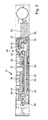
- Fig. 1 to 7 show a schematic representation of an exemplary embodiment of a door drive 10 according to the invention, in the illustration according to Fig. 1 for example, is provided as a top door closer for a revolving door.
- the door drive 10 includes a housing 12, a rotatably mounted in the housing 12 and coupled to a door leaf 14 or a frame 16 output shaft 18, a motor 20, in particular electric motor for driving the output shaft 18 and a spring unit 22, during a respective opening movement of the Door leaf 14 is tensioned and relaxes during a respective closing movement of the door leaf 14 to provide a closing moment.
- the door drive 10 in the illustration according to Fig. 1 For example, provided as a top door closer for a revolving door.
- the housing 12 is mounted with the output shaft 18 on the door leaf 14 and the output shaft 18 connected to a lever 24 which is provided with a sliding block or the like, which is guided in a slide rail 26 which is fixed to the frame 16.
- the output shaft 18 via a rack 28 by the motor 20 can be driven, which is acted upon by a front-bevel gear 30 having a motor side helical Stirnradgetriebeabêt 32, a rack-side spur gear 34, a straight spur gear portion 37 and an intermediate arranged, in particular provided with a Gleason toothing bevel gear section 36 includes.
- the motor-side helical spur gear section 32 comprises a helical geared pinion 40 connected to a motor shaft 38 and a helical spur gear 42 meshing therewith.
- the helical spur gear 42 of the motor-side helical spur gear section 32 may consist in particular of a carbon fiber reinforced polyamide-containing material.
- the bevel gear section 36 comprises a bevel gear meshing with a bevel gear 44, which is connected to the helical spur gear 42 of the motor side helical spur gear section 32.
- the helical spur gear 42 of the motor-side helical spur gear portion 32 and the bevel gear 46 of the bevel gear portion 36 are arranged on a common shaft 48 which is arranged by a ball bearing 50 (see, in particular, Figs Fig. 3 and 4 ) is supported. How, in particular, the Fig. 3 and 4 can be taken is the shaft 48, which is provided with the helical spur gear 42 of the motor-side helical spur gear section 32 and the bevel pinion 46 of the bevel gear section 36, is also supported by a ball bearing 52 arranged on the side of the helical spur gear 42 facing away from the bevel pinion 46.
- the bevel gear 44 of the bevel gear section 36 and the spur gear 58 of the spur geared spur gear section 37 may in particular be designed as a one-piece sintered part.
- the rack-side straight-toothed spur gear portion 34 includes a spur gear 54 meshing with the rack gear 28 and a spur gear 56 connected to this spur gear 54 meshing with a spur gear 58 connected to the bevel gear 44 of the bevel gear portion 36.
- the spur gear 54 and the straight-toothed spur gear 56 of the rack-side spur gear portion 34 may be configured as a one-piece sintered part.
- the spring unit 22 may comprise a pushed onto the rack 28 compression spring.
- the spring unit 22 is arranged between an axially adjustable sleeve 60 pushed onto the rack 28 and a thrust bearing 62 supported on a contact disk 64 or the like.
- the sleeve 60 is, for example via a worm gear 66 (see Fig. 3 ) axially adjustable.
- the toothed rack 28 comprises a toothed section 68, which meshes with the spur gear 54 of the toothed rack-side spur gear section 34, and a toothing section 70 which is arranged in particular on the same side and which meshes with a toothing 72 of the output shaft 18.
- the rack 28 may in particular comprise a wave-shaped toothed portion 70 which meshes with a non-circular toothing 72 of the output shaft 18.
- the provided with the helical spur gear 42 and the bevel pinion 46 shaft 48 may be provided, for example in the form of a bevel pin bolt on which the helical spur gear 42 is fixed by means of a Knebelkerbx, which arranged between the helical gear and the bevel pinion 46 ball bearing 50 Axial - And radial forces can absorb and the bevel pinion 46 is positioned exactly relative to the bevel gear 44.
- the rack 28 may in the region of their with the spur gear 54 of the rack-side spur gear 34 and meshing with the teeth 72 of the output shaft 18 toothing portions 68, 70 each have a on the side facing away from the respective toothed portion 68, 70 side of the rack 28 in particular roller bearing roller , Cylindrical pin 74 (see Fig. 5 and 7 ) or the like.
- the pinion 54 of the rack-side straight-toothed spur gear portion 34 thus pulls the toothed rack 28 with module toothing into the front-bevel gear 30, which on the other hand is pushed out of the front-bevel gear 30 by the spring unit 22.
- the rack 28 penetrates the sleeve 60, the spring unit 22 and the thrust bearing 62 with the bearing plate 64.
- the spring force and thus the closing force can be adjusted in the currentless operation.
- By rolling rollers or cylindrical pins 74 a reliable tooth engagement is guaranteed.
- the sleeve 60 can be moved axially via the worm drive 66, for example a worm with an Allen key.
- the output shaft 18 may be provided with a bore which has, for example, a serration with, for example, thirty-one teeth for torque transmission to the lever 24 driving the door leaf 14.
- the door drive 10 may be provided with a transmission housing 76, a gear cover 77 (cf. Fig. 3 and 4 ), a tension profile and a bearing plate be provided.
- the prestressed spring unit 22 In the storable assembly train profile and bearing plate, the prestressed spring unit 22, the rack 28 and the output shaft 18 may be arranged.
- the tension profile is closed by the adjustable sleeve 60 and on the other side by the lid 78. In between, the spring unit 22 is clamped.
- the rack 28 extends through the sleeve 60 through to the outside.
- the gear wheels and the assembly profile and bearing plate are inserted into the gearbox.
- the gear cover 77 closes the gear while holding the module train profile and bearing plate in position.
- the motor 20 may be attached to a bearing plate 80 (see in particular the Fig. 2 and 3 ), which can be screwed to the transmission housing 76.
- the helical motor pinion 40 may be pressed onto the motor shaft 38.
- the pinions can have a very small number of teeth.
- the motor pinion 40 may have four to seven teeth and the bevel pinion provided with a Gleason toothing may have five teeth, for example, while the straight toothed pinion 54 of the rack-side straight toothed spur gear portion 34 may have seven teeth.
- the straight toothed pinion 54 of the rack-side straight toothed spur gear portion 34 may have seven teeth.
- a profile coverage greater than 1 ensures a smooth running of the gear stages, i. before the first tooth is disengaged, the second is already engaged.
- the door drive 10 may also include a transformer and control electronics.
- the motor 20 drives the toothed rod 28 via the front-bevel gear 30 and via this the output shaft 18 in order to open the door leaf 14 via the lever 24.
- the now-tensioned spring unit 22 drives the front-bevel gear 30 and the motor 20 and rotates the output shaft 18 with the lever 24 in the opposite direction.
- the engine now operates in generator mode and controls the closing speed and the end impact of the door leaf 14 via the control electronics.
- the closing of the door leaf 14 also works normally, which is mandatory for fire door drives.
Abstract
Ein Türantrieb, insbesondere Drehtürantrieb, umfasst ein Gehäuse (12), eine mit einem Türflügel oder einem Blendrahmen koppelbare Abtriebsachse (18), einen Motor (20) zum Antreiben der Abtriebsachse (18) und eine Federeinheit (22), die während einer jeweiligen Öffnungsbewegung des Türflügels gespannt wird und sich während einer jeweiligen Schließbewegung des Türflügels entspannt. Dabei ist die Abtriebsachse (18) über eine Zahnstange (28) durch den Motor (20) antreibbar, wobei die Zahnstange (28) über ein Stirn-Kegel-Getriebe (30) beaufschlagbar ist, das einen motorseitigen schrägverzahnten Stirnradgetriebeabschnitt (32), einen zahnstangenseitigen geradverzahnten Stirnradgetriebeabschnitt (34) und einen dazwischen angeordneten, insbesondere mit einer Gleason-Verzahnung versehenen Kegelgetriebeabschnitt (36) umfasst.A door drive, in particular a swing door drive, comprises a housing (12), an output shaft (18) which can be coupled to a door leaf or a frame, a motor (20) for driving the output shaft (18) and a spring unit (22) during a respective opening movement the door leaf is tensioned and relaxes during a respective closing movement of the door leaf. In this case, the output shaft (18) via a rack (28) by the motor (20) can be driven, wherein the rack (28) via a front-bevel gear (30) can be acted upon, the an engine-side helical spur gear portion (32) Ratchet-side spur gear portion (34) and arranged therebetween, in particular provided with a Gleason toothing bevel gear portion (36).
Description
Die vorliegende Erfindung betrifft einen Türantrieb, insbesondere Drehtürantrieb, mit einem Gehäuse, einer mit einem Türflügel oder einem Blendrahmen koppelbaren Abtriebsachse, einem Motor zum Antreiben der Abtriebsachse und einer Federeinheit, die während einer jeweiligen Öffnungsbewegung des Türflügels gespannt wird und sich während einer jeweiligen Schließbewegung des Türflügels entspannt.The present invention relates to a door drive, in particular swing door drive, with a housing, a coupling with a door leaf or a frame output shaft, a motor for driving the output shaft and a spring unit, which is tensioned during a respective opening movement of the door and during a respective closing movement of the Door leaf relaxed.
Derartige Türantriebe dienen dazu, den Flügel einer motorisch geöffneten Tür mit Federkraft zu schließen. Dies ist insbesondere bei Rauch- und Feuerschutztüren von Bedeutung, die im Alarmfall, insbesondere nach Ansprechen eines Rauchmelders oder bei Stromausfall, schnell und zuverlässig geschlossen werden müssen. Mit dem Öffnen des Türflügels wird gleichzeitig die Federeinheit gespannt. Mit Hilfe der Federeinheit kann der Türantrieb den Türflügel somit auch bei einem Stromausfall schließen, was bei Brandschutztüren zwingend ist.Such door drives are used to close the wing of a motorized door with spring force. This is particularly important in smoke and fire doors of importance, which must be closed quickly and reliably in case of alarm, especially after responding to a smoke detector or power failure. By opening the door leaf, the spring unit is tensioned at the same time. With the aid of the spring unit, the door drive can thus close the door leaf even in the event of a power failure, which is mandatory with fire doors.
Die bisher üblichen Drehtürantriebe der eingangs genannten Art sind relativ raumgreifend und voluminös und in der Herstellung relativ kostspielig.The usual swing door drives of the type mentioned are relatively bulky and bulky and relatively expensive to manufacture.
Der Erfindung liegt die Aufgabe zugrunde, einen Türantrieb, insbesondere Drehtürantrieb, der eingangs genannten Art anzugeben, der einen kompakteren Aufbau besitzt und kostengünstiger herstellbar ist.The invention has for its object to provide a door drive, in particular revolving door drive, of the type mentioned above, which has a more compact structure and is cheaper to produce.
Die Aufgabe wird erfindungsgemäß durch einen Türantrieb mit den Merkmalen des Anspruchs 1 gelöst. Bevorzugte Ausführungsformen des erfindungsgemäßen Türantriebs ergeben sich aus den Unteransprüchen, der vorliegenden Beschreibung sowie der Zeichnung.The object is achieved by a door drive with the features of claim 1. Preferred embodiments of the door drive according to the invention will become apparent from the dependent claims, the present description and the drawings.
Der erfindungsgemäße Türantrieb, insbesondere Drehtürantrieb, umfasst ein Gehäuse, eine mit einem Türflügel oder einem Blendrahmen koppelbare Abtriebsachse, einen Motor zum Antreiben der Abtriebsachse und eine Federeinheit, die während einer jeweiligen Öffnungsbewegung des Türflügels gespannt wird und sich während einer jeweiligen Schließbewegung des Türflügels entspannt. Dabei ist die Abtriebsachse über eine Zahnstange durch den Motor antreibbar, die über ein Stirn-Kegel-Getriebe beaufschlagbar ist, das einen motorseitigen schrägverzahnten Stirnradgetriebeabschnitt, einen zahnstangenseitigen geradverzahnten Stirnradgetriebeabschnitt und einen dazwischen angeordneten, insbesondere mit einer Gleason-Verzahnung versehenen Kegelgetriebeabschnitt umfasst.The door drive according to the invention, in particular revolving door drive, comprises a housing, an output shaft which can be coupled to a door leaf or a frame, a motor for driving the output shaft and a spring unit which is tensioned during a respective opening movement of the door leaf and relaxes during a respective closing movement of the door leaf. In this case, the output shaft via a rack by the motor can be driven, which is acted upon by a front-bevel gear, which includes a motor side helical Stirnradgetriebeabschnitt, a rack-side straight spur gear and arranged therebetween, in particular provided with a Gleason toothing bevel gear section.
Aufgrund dieser Ausbildung ergibt sich ein insgesamt kompakterer und einfacherer Aufbau des Türantriebs, womit auch die Herstellungskosten deutlich reduziert werden. Die bevorzugt vorgesehene Gleason-Verzahnung des Kegelgetriebeabschnitts zeichnet sich dadurch aus, dass die Kanten der Zahnrücken eine Spirale bilden.Due to this design results in a total of more compact and simpler construction of the door drive, which also significantly reduces the cost of production. The preferably provided Gleason toothing of the bevel gear section is characterized in that the edges of the tooth back form a spiral.
Der motorseitige schrägverzahnte Stirnradgetriebeabschnitt umfasst bevorzugt ein mit einer Motorwelle verbundenes schrägverzahntes Motorritzel und ein mit diesem kämmendes schrägverzahntes Stirnrad.The motor-side helical spur gear section preferably comprises a helical gear pinion connected to a motor shaft and a helical spur gear meshing therewith.
Dabei besteht das schrägverzahnte Stirnrad des motorseitigen schrägverzahnten Stirnradgetriebeabschnitts gemäß einer bevorzugten praktischen Ausführungsform des erfindungsgemäßen Türantriebs aus einem kohlenfaserverstärktes Polyamid enthaltenden Material, womit eine entsprechende Geräuschreduzierung erreicht wird.In this case, there is the helical spur gear of the motor side helical Stirnradgetriebeabschnitts according to a preferred practical embodiment of the door drive according to the invention of a carbon fiber reinforced polyamide-containing material, whereby a corresponding noise reduction is achieved.
Der Kegelgetriebeabschnitt umfasst vorteilhafterweise ein mit einem Kegelrad kämmendes Kegelritzel, das mit dem schrägverzahnten Stirnrad des motorseitigen schrägverzahnten Stirnradgetriebeabschnitts verbunden ist.The bevel gear portion advantageously comprises a bevel gear meshing with a bevel gear, which is connected to the helical spur gear of the motor side helical Stirnradgetriebeabschnitts.
Dabei sind das schrägverzahnte Stirnrad des motorseitigen schrägverzahnten Stirnradgetriebeabschnitts und das Kegelritzel des Kegelgetriebeabschnitts bevorzugt auf einer gemeinsamen Welle angeordnet, die durch ein axial zwischen dem schrägverzahnten Stirnrad und dem Kegelritzel angeordnetes Kugellager abgestützt ist.In this case, the helical spur gear of the motor side helical spur gear portion and the bevel pinion of the bevel gear portion are preferably arranged on a common shaft which is supported by an axially disposed between the helical spur gear and the bevel pinion ball bearing.
Hierbei kann die gemeinsame Welle beispielsweise in Form eines Kegelritzel-Bolzens vorgesehen und das schrägverzahnte Stirnrad mittels eines Knebelkerbstiftes auf dem Kegelritzel-Bolzen fixiert sein. Das zwischen dem schrägverzahnten Stirnrad und dem Kegelritzel angeordnete Kugellager kann damit Axial- und Radialkräfte aufnehmen, wodurch das Kegelritzel sehr genau relativ zum Kegelrad positionierbar ist.Here, the common shaft may be provided, for example, in the form of a bevel pinion bolt and the helical spur gear be fixed by means of a toggle plug on the bevel pinion bolt. The arranged between the helical gear and the bevel pinion ball bearing can thus absorb axial and radial forces, whereby the bevel pinion is positioned very accurately relative to the bevel gear.
Die mit dem schrägverzahnten Stirnrad des motorseitigen schrägverzahnten Stirnradgetriebeabschnitts und mit dem Kegelritzel des Kegelgetriebeabschnitts versehene Welle kann zudem durch ein auf der vom Kegelritzel abgewandten Seite des schrägverzahnten Stirnrades angeordnetes Kugellager abgestützt sein.The provided with the helical gear of the helical side helical gear portion and the bevel pinion of the bevel gear portion shaft can also be supported by a arranged on the side facing away from the bevel pinion of the helical spur gear ball bearing.
Das Kegelrad des Kegelgetriebeabschnitts und das geradverzahnte Stirnrad des geradverzahnten Stirnradgetriebeabschnitts sind bevorzugt als einteiliges Sinterteil ausgeführt, womit die Herstellungskosten für den Türantrieb reduziert werden und ein möglichst kompakter Aufbau erreicht wird.The bevel gear of the bevel gear portion and the spur gear of the straight spur gear portion are preferably designed as a one-piece sintered part, whereby the manufacturing cost of the door drive can be reduced and the most compact design is achieved.
Das Kegelrad und das betreffende geradverzahnte Stirnrad können somit als einteiliges Sinterteil mit zwei Verzahnungen und einem beispielsweise siebenzahnigen Stirnrad gefertigt werden.The bevel gear and the spur gear spur gear in question can thus be made as one-piece sintered part with two teeth and a, for example, seven-toothed spur gear.
Der zahnstangenseitige geradverzahnte Stirnradgetriebeabschnitt kann insbesondere ein mit der Zahnstange kämmendes geradverzahntes Ritzel und ein mit diesem geradverzahnten Ritzel verbundenes geradverzahntes Stirnrad umfassen, das mit einem mit dem Kegelrad des Kegelgetriebeabschnitts verbundenen geradverzahnten Ritzel kämmt.The rack-side straight-toothed spur gear portion may in particular comprise a spur gear meshing with the rack and a spur gear connected to this spur pinion meshing with a spur pinion connected to the bevel gear of the bevel gear portion.
Dabei ist insbesondere auch von Vorteil, wenn das geradverzahnte Ritzel und das geradverzahnte Stirnrad des zahnstangenseitigen geradverzahnten Stirnradgetriebeabschnitts als einteiliges Sinterteil ausgeführt sind, womit die Herstellungskosten für den Türantrieb weiterer reduziert werden und der Türantrieb im Aufbau relativ kompakter gehalten wird. Die Federeinheit umfasst bevorzugt eine auf die Zahnstange aufgeschobene Druckfeder, was insbesondere wieder hinsichtlich eines möglichst kompakten Aufbaus des Türantriebs von Vorteil ist.It is particularly advantageous if the spur gear and the straight-toothed spur gear of the rack-side spur gear portion are designed as one-piece sintered part, whereby the manufacturing cost of the door drive are further reduced and the door drive is kept relatively compact in construction. The spring unit preferably comprises a pushed onto the rack compression spring, which in particular again in terms of a compact construction of the door drive is advantageous.
Gemäß einer weiteren bevorzugten praktischen Ausführungsform des erfindungsgemäßen Türantriebs ist die Federeinheit zwischen einer auf die Zahnstange aufgeschobenen axial verstellbaren Hülse und einem an einer Anlagescheibe oder dergleichen abgestützten Axiallager angeordnet. Dabei kann die Hülse insbesondere über ein Schneckengetriebe axial verstellbar sein.According to a further preferred practical embodiment of the door drive according to the invention, the spring unit is arranged between an axially adjustable sleeve pushed onto the rack and a thrust bearing supported on a contact disk or the like. In this case, the sleeve can be axially adjustable in particular via a worm gear.
Über das Ritzel der dritten Stufe des Stirn-Kegel-Getriebes kann die Zahnstange mit Modulverzahnung einerseits motorisch in das Getriebe eingezogen werden, die andererseits durch die Federeinheit aus dem Getriebe herausgedrückt wird. Die Zahnstange kann sich durch die Hülse, die Federeinheit und das Axiallager mit Anlagescheibe hindurch erstrecken. Über die Hülse kann die Federkraft und damit die Schließkraft im stromlosen Betrieb eingestellt werden.About the pinion of the third stage of the front-cone transmission, the rack can be retracted with a module toothing on the one hand motor in the transmission, on the other hand pushed out by the spring unit from the transmission. The rack may extend through the sleeve, the spring unit and the thrust bearing thrust washer. About the sleeve, the spring force and thus the closing force can be adjusted in the currentless operation.
Bevorzugt umfasst die Zahnstange einen mit dem geradverzahnten Ritzel des zahnstangenseitigen geradverzahnten Stirnradgetriebeabschnitts kämmenden Verzahnungsabschnitt sowie im Bereich ihres gegenüberliegenden Endes einen insbesondere auf derselben Seite angeordneten Verzahnungsabschnitt, der mit einer Verzahnung der Abtriebsachse kämmt. Die Verzahnungsabschnitte der Zahnstange können also auf derselben Seite der Zahnstange vorgesehen sein, d.h. in dieselbe Richtung weisen.The toothed rack preferably comprises a toothed section meshing with the spur-toothed pinion of the toothed-rack-side spur gear section and, in the region of its opposite end, a toothed section arranged in particular on the same side and meshing with a toothing of the output shaft. The toothed portions of the rack may thus be provided on the same side of the rack, i. pointing in the same direction.
Um möglichst zuverlässige Zahneingriffe zu gewährleisten, ist die Zahnstange im Bereich deren mit dem geradverzahnten Ritzel des zahnstangenseitigen geradverzahnten Stirnradgetriebeabschnitts und mit der Verzahnung der Abtriebsachse kämmenden Verzahnungsabschnitten bevorzugt über jeweils wenigstens eine auf der vom jeweiligen Verzahnungsabschnitt abgewandten Seite der Zahnstange angeordnete insbesondere wälzgelagerte Rolle, Zylinderstift oder dergleichen abgestützt.In order to ensure the most reliable meshing, the rack is in the range of the sprocket-toothed straight spur gear and meshing with the teeth of the output shaft meshing toothed sections preferably in each case at least one on the side facing away from the respective toothed portion of the rack particular roller bearing roller, cylinder pin or supported.
Die Zahnstange umfasst bevorzugt einen wellenförmigen Verzahnungsabschnitt, der mit einer Unrund-Verzahnung der Abtriebsachse kämmt.The toothed rack preferably comprises a wave-shaped toothed section, which meshes with a non-circular toothing of the output shaft.
Mit einer solchen Gestaltung der zusammenwirkenden Verzahnungen der Abtriebsachse und der Zahnstange kann das sich ergebende Schließ- und Öffnungsmoment in der gewünschten Weise beeinflusst werden. So kann ein jeweils gewünschter Verlauf des Schließ- und Öffnungsmoments insbesondere durch eine entsprechende Wahl der Wellenform des Verzahnungsabschnitts der Zahnstange und eine entsprechende Wahl der Form der Unrund-Verzahnung der Abtriebsachse vorgegeben werden.With such a design of the cooperating teeth of the output shaft and the rack, the resulting closing and opening torque can be influenced in the desired manner. Thus, a respective desired course of the closing and opening torque can be specified in particular by an appropriate choice of the waveform of the toothed portion of the rack and a corresponding choice of the shape of the non-circular toothing of the output shaft.
Vorzugsweise weist der Türantrieb mindestens ein Ritzel auf, das eine Zähnezahl zwischen drei und acht Zähnen aufweist. Somit sind mit einer sehr kleinen Anzahl von Zähnen möglichst kleine, stabile Zahnräder zu realisieren.Preferably, the door drive has at least one pinion, which has a number of teeth between three and eight teeth. Thus, with a very small number of teeth as small as possible to realize stable gears.
Der Türantrieb kann an einem Türflügel oder einem Blendrahmen angeordnet sein. Die Abtriebsachse des Türantriebs kann über einen Hebel oder ein Gestänge mit dem Blendrahmen bzw. dem Türflügel in Verbindung stehen.The door drive can be arranged on a door leaf or a frame. The output shaft of the door drive can be connected via a lever or linkage with the frame or the door in conjunction.
Die Abtriebsachse kann beispielsweise eine Bohrung mit Kerbverzahnung und beispielsweise einunddreißig Zähnen zur Drehmomentübertragung auf den Hebel bzw. das Gestänge umfassen.The output shaft may comprise, for example, a bore with serration and, for example, thirty-one teeth for torque transmission to the lever or the linkage.
Es können beispielsweise ein Getriebegehäuse, ein Getriebedeckel sowie ein Zugprofil und eine Lagerplatte vorgesehen sein, wobei in der das Zugprofil und die Lagerplatte umfassenden lagerfähigen Baugruppe die vorgespannte Federeinheit, die Zahnstange und die Abtriebsachse eingesteckt werden können. Das Zugprofil kann auf der einen Seite über die Hülse verschlossen werden, während es auf der anderen Seite mit einem Deckel verschlossen wird. Dazwischen kann die Federeinheit eingespannt sein. Die Zahnstange kann aus der Hülse herausragen. Die beispielsweise angeschraubte Lagerplatte kann zusammen mit dem Zugprofil die Lagerstellen für die Abtriebsachse bilden.It may, for example, a gear housing, a gear cover and a tension profile and a bearing plate may be provided, in which the tension profile and the bearing plate comprehensive storable assembly, the preloaded spring unit, the rack and the output shaft can be inserted. The pull profile can be closed on one side over the sleeve, while it is closed on the other side with a lid. In between, the spring unit can be clamped. The rack can protrude from the sleeve. The example screwed bearing plate can form together with the tension profile bearing points for the output shaft.
Der Motor kann an einem Lagerschild befestigt sein, das am Getriebegehäuse und Getriebedeckel angeschraubt wird.The motor can be attached to a bearing plate, which is screwed to the gear housing and gear cover.
Das schrägverzahnte Motorritzel kann beispielsweise auf der Motorwelle aufgepresst sein.The helical motor pinion can be pressed for example on the motor shaft.
Um möglichst kleine, stabile Zahnräder zu erhalten, können die Ritzel jeweils eine sehr kleine Anzahl von Zähnen, beispielsweise zwischen drei und acht Zähnen besitzen. So kann das Motorritzel abhängig von der gewünschten Übersetzung beispielsweise vier bis sieben Zähne und das Kegelritzel beispielsweise fünf Zähne, das geradverzahnte Stirnritzel in Verbindung mit dem Kegelrad beispielsweise sieben Zähne und das mit der Zahnstange kämmende geradverzahnte Ritzel beispielsweise sieben Zähne aufweisen. Für eine Profilüberdeckung der Verzahnungen von über 1 sind das nahezu die kleinsten möglichen Zähnezahlen. Eine Profilüberdeckung größer als 1 gewährleistet einen stoßfreien Lauf der Getriebestufen, d.h. bevor der erste Zahn außer Eingriff gelangt, ist der zweite Zahn schon in Eingriff. Die kleinen Ritzelzähnezahlen führen einerseits zu kleinen Getriebeabmessungen und zu stabilen Zähnen bei großen Übersetzungen pro Getriebestufe. Andererseits schafft dies die Voraussetzung dafür, die Zahnräder sintern zu können, ohne das Risiko eines Zahnbruchs einzugehen, da das Sintermaterial eine geringere Festigkeit besitzt als der üblicherweise verwendete Stahl. Mit Sinterzahnrädern lassen sich die Herstellungskosten im Vergleich zu Stahlzahnrädern, die spanend hergestellt werden müssen, um den Faktor 5 bis 10 reduzieren.In order to obtain the smallest possible, stable gears, the pinions can each have a very small number of teeth, for example, between three and eight teeth. Thus, the motor pinion depending on the desired translation, for example, four to seven teeth and the bevel pinion, for example, five teeth, the spur gear spur in conjunction with the bevel gear, for example, seven teeth and the meshing with the rack spur pinion, for example, seven teeth. For a profile overlap of the teeth of more than 1, this is almost the smallest possible number of teeth. A profile coverage greater than 1 assures a smooth running of the gear stages, i. before the first tooth is disengaged, the second tooth is already engaged. The small pinion gear numbers lead on the one hand to small gear dimensions and to stable teeth with large ratios per gear stage. On the other hand, this creates the prerequisite for being able to sinter the gears without the risk of tooth breakage, since the sintered material has a lower strength than the steel commonly used. With sintered gears, the manufacturing costs can be reduced by a factor of 5 to 10 compared to steel gears that have to be machined.
Der Türantrieb kann zudem mit einem Transformator versehen sein, um die Spannung beispielsweise von 230 V auf 24 V zu reduzieren, sowie eine Steuerelektronik umfassen. Zudem kann der Türantrieb endseitig mit Deckeln versehen sein und eine Abdeckhaube umfassen.The door drive can also be provided with a transformer to reduce the voltage, for example, from 230 V to 24 V, and include control electronics. In addition, the door drive may be provided at the end with lids and include a cover.
Der Motor treibt über das Motorritzel und das Stirn-Kegel-Getriebe die Zahnstange und über diese die Abtriebsachse an, über die entsprechend ein Hebel oder Gestänge beaufschlagt wird, um den Türflügel zu öffnen. Beim Schließen des Türflügels treibt die zuvor gespannte Federeinheit das Getriebe und den Motor an, wodurch die Abtriebsachse mit dem Hebel bzw. Gestänge in die andere Richtung gedreht und verstellt werden. Dabei kann der Motor in den Generatorbetrieb übergehen und über die Steuerelektronik die Schließgeschwindigkeit und den Endschlag des Türflügels steuern.The motor drives the gear rack via the motor pinion and the front-bevel gear and via this the output shaft, which is used to apply a lever or linkage to open the door leaf. When closing the door leaf, the previously tensioned spring unit drives the gearbox and the engine, whereby the output shaft with the lever or linkage in the other direction are rotated and adjusted. In this case, the engine can go into generator mode and control the closing speed and the end impact of the door leaf via the control electronics.
Das Schließen des Türflügels funktioniert auch stromlos, was für Brandschutz-Drehtürantriebe zwingend ist.The closing of the door leaf also works without power, which is mandatory for fire protection swing door drives.
Die Unrund-Verzahnung der Abtriebsachse und der mit dieser kämmende wellenförmige Verzahnungsabschnitt der Zahnstange können insbesondere so gestaltet sein, dass das von der Federeinheit auf die Abtriebsachse übertragene Drehmoment mit zunehmendem Öffnungswinkel des Türflügels abnimmt. Dabei sind die Unrund-Verzahnung der Abtriebsachse und der mit dieser kämmende wellenförmige Verzahnungsabschnitt der Zahnstange bevorzugt so gestaltet, dass das von der Federeinheit auf die Abtriebsachse übertragene Drehmoment ab einem Öffnungswinkel des Türflügels im Bereich von 4° mit zunehmendem Öffnungswinkel des Türflügels abnimmt. Indem sich der Wälzkreis von groß zu klein verändert, wird bei kleinen Türöffnungswinkeln ein größeres Drehmoment erzeugt als bei größeren Öffnungswinkeln. Damit werden die Anforderungen hinsichtlich eines großen Türschließmoments bei Türöffnungswinkeln im Bereich von 0° bis 4° und eines schnell abfallenden Türschließmoments bei größeren Türöffnungswinkeln mit einem kleineren Motor erreicht.The non-circular toothing of the output shaft and the meshing with this wave-shaped toothed portion of the rack may in particular be designed so that the torque transmitted from the spring unit to the output shaft torque decreases with increasing opening angle of the door leaf. Here, the non-circular toothing of the output shaft and the meshing with this wave-shaped toothed portion of the rack are preferably designed so that the torque transmitted from the spring unit to the output shaft torque decreases from an opening angle of the door leaf in the range of 4 ° with increasing opening angle of the door leaf. By changing the pitch circle from big to small, a larger torque is generated at small door opening angles than at larger opening angles. Thus, the requirements for a large door closing torque at door opening angles in the range of 0 ° to 4 ° and a rapidly decreasing door closing torque are achieved with larger door opening angles with a smaller motor.
Der erfindungsgemäße Türantrieb besitzt eine gegenüber den bisherigen Antrieben geringere Ansichtshöhe. Beim stromlosen Begehen der Tür ist bei einem Öffnungswinkel oberhalb 4° weniger Kraft erforderlich als zuvor. Mit den gesinterten Zahnrädern werden die Herstellungskosten minimiert. Es ist nunmehr der Einsatz kleinerer und entsprechend kostengünstigerer Motoren und Trafos möglich. Zudem ergibt sich mit einem kleineren Motor und kompakteren Komponenten auch ein geringeres Gesamtgewicht des Türantriebs.The door drive according to the invention has a lower height compared to the previous drives. When powering the door is less power required at an opening angle above 4 ° than before. With the sintered gears, the manufacturing costs are minimized. It is now possible to use smaller and correspondingly less expensive motors and transformers. In addition, with a smaller engine and more compact components also results in a lower total weight of the door drive.
Die Erfindung wird im Folgenden anhand eines Ausführungsbeispiels unter Bezugnahme auf die Zeichnung näher erläutert; in dieser zeigen:
- Fig. 1
- eine schematische Darstellung einer beispielhaften Ausführungsform eines beispielsweise als Obentürschließer vorgesehenen erfindungsgemäßen Türantriebs,
- Fig. 2
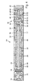
- eine schematische Schnittdarstellung des Türantriebs gemäß
Fig. 1 , - Fig. 3
- eine vergrößerte schematische geschnittene Draufsicht des das Stirn-Kegel-Getriebe, die Zahnstange und die Abtriebsachse umfassenden Teils des Türantriebs gemäß
Fig. 1 , - Fig. 4
- eine vergrößerte schematische geschnittene Seitenansicht des das Stirn-Kegel-Getriebe, die Zahnstange und die Abtriebsachse umfassenden Teils des Türantriebs gemäß
Fig. 1 , - Fig. 5
- eine schematische Draufsicht des Stirn-Kegel-Getriebes, der Zahnstange und der Abtriebsachse des Türantriebs gemäß
Fig. 1 , - Fig. 6
- eine schematische Seitenansicht des Stirn-Kegel-Getriebes, der Zahnstange und der Abtriebsachse des Türantriebs gemäß
Fig. 1 und - Fig. 7
- eine schematische perspektivische Ansicht des Stirn-Kegel-Getriebes, der Zahnstange und der Abtriebsachse des Türantriebs gemäß
Fig. 1 .
- Fig. 1
- a schematic representation of an exemplary embodiment of an example provided as overhead door closer invention door drive according to the invention,
- Fig. 2
- a schematic sectional view of the door drive according to
Fig. 1 . - Fig. 3
- an enlarged schematic sectional plan view of the front-bevel gear, the rack and the output axis comprising part of the door drive according to
Fig. 1 . - Fig. 4
- an enlarged schematic sectional side view of the front-bevel gear, the rack and the output axis comprising part of the door drive according to
Fig. 1 . - Fig. 5
- a schematic plan view of the front-cone gear, the rack and the output shaft of the door drive according to
Fig. 1 . - Fig. 6
- a schematic side view of the front-cone gear, the rack and the output shaft of the door drive according to
Fig. 1 and - Fig. 7
- a schematic perspective view of the front-cone gear, the rack and the output shaft of the door drive according to
Fig. 1 ,
Die
Der Türantrieb 10 umfasst ein Gehäuse 12, eine drehbar im Gehäuse 12 gelagerte und mit einem Türflügel 14 oder einem Blendrahmen 16 koppelbare Abtriebsachse 18, einen Motor 20, insbesondere Elektromotor, zum Antreiben der Abtriebsachse 18 und eine Federeinheit 22, die während einer jeweiligen Öffnungsbewegung des Türflügels 14 gespannt wird und sich während einer jeweiligen Schließbewegung des Türflügels 14 entspannt, um ein Schließmoment zu liefern.The door drive 10 includes a
Dabei ist der Türantrieb 10 in der Darstellung gemäß
Wie den
Dabei umfasst der motorseitige schrägverzahnte Stirnradgetriebeabschnitt 32 ein mit einer Motorwelle 38 verbundenes schrägverzahntes Motorritzel 40 und ein mit diesem kämmendes schrägverzahntes Stirnrad 42.In this case, the motor-side helical
Das schrägverzahnte Stirnrad 42 des motorseitigen schrägverzahnten Stirnradgetriebeabschnitts 32 kann insbesondere aus einem kohlefaserverstärkten Polyamid enthaltendem Material bestehen.The
Der Kegelgetriebeabschnitt 36 umfasst ein mit einem Kegelrad 44 kämmendes Kegelritzel 46, das mit dem schrägverzahnten Stirnrad 42 des motorseitigen schrägverzahnten Stirnradgetriebeabschnitts 32 verbunden ist.The
Das schrägverzahnte Stirnrad 42 des motorseitigen schrägverzahnten Stirnradgetriebeabschnitts 32 und das Kegelritzel 46 des Kegelgetriebeabschnitts 36 sind auf einer gemeinsamen Welle 48 angeordnet, die durch ein axial zwischen dem schrägverzahnten Stirnrad 42 und dem Kegelritzel 46 angeordnetes Kugellager 50 (vgl. insbesondere die
Das Kegelrad 44 des Kegelgetriebeabschnitts 36 und das geradverzahnte Ritzel 58 des geradverzahnten Stirnradgetriebeabschnitts 37 können insbesondere als einteiliges Sinterteil ausgeführt sein.The
Der zahnstangenseitige geradverzahnte Stirnradgetriebeabschnitt 34 umfasst ein mit der Zahnstange 28 kämmendes geradverzahntes Ritzel 54 und ein mit diesem geradverzahnten Ritzel 54 verbundenes geradverzahntes Stirnrad 56, das mit einem mit dem Kegelrad 44 des Kegelgetriebeabschnitts 36 verbundenen geradverzahnten Ritzel 58 kämmt.The rack-side straight-toothed
Dabei können auch das geradverzahnte Ritzel 54 und das geradverzahnte Stirnrad 56 des zahnstangenseitigen geradverzahnten Stirnradgetriebeabschnitts 34 als einteiliges Sinterteil ausgeführt sein.In this case, the
Wie insbesondere wieder anhand der
Die Zahnstange 28 umfasst einen mit dem geradverzahnten Ritzel 54 des zahnstangenseitigen geradverzahnten Stirnradgetriebeabschnitts 34 kämmenden Verzahnungsabschnitt 68 sowie im Bereich ihres gegenüberliegenden Endes einen insbesondere auf derselben Seite angeordneten Verzahnungsabschnitt 70, der mit einer Verzahnung 72 der Abtriebsachse 18 kämmt.The
Dabei kann die Zahnstange 28 insbesondere einen wellenförmigen Verzahnungsabschnitt 70 umfassen, der mit einer Unrund-Verzahnung 72 der Abtriebsachse 18 kämmt.In this case, the
Die mit dem schrägverzahnten Stirnrad 42 und dem Kegelritzel 46 versehene Welle 48 kann beispielsweise in Form eines Kegelritzel-Bolzens vorgesehen sein, auf dem das schrägverzahnte Stirnrad 42 mittels eines Knebelkerbstiftes fixiert ist, womit das zwischen dem schrägverzahnten Stirnrad und dem Kegelritzel 46 angeordnete Kugellager 50 Axial- und Radialkräfte aufnehmen kann und das Kegelritzel 46 exakt relativ zum Kegelrad 44 positioniert wird.The provided with the
Die Zahnstange 28 kann im Bereich deren mit dem geradverzahnten Ritzel 54 des zahnstangenseitigen geradverzahnten Stirnradgetriebeabschnitts 34 und mit der Verzahnung 72 der Abtriebsachse 18 kämmenden Verzahnungsabschnitten 68, 70 jeweils über eine auf der vom jeweiligen Verzahnungsabschnitt 68, 70 abgewandten Seite der Zahnstange 28 angeordnete insbesondere wälzgelagerte Rolle, Zylinderstift 74 (vgl. die
Das Ritzel 54 des zahnstangenseitigen geradverzahnten Stirnradgetriebeabschnitts 34 zieht die Zahnstange 28 mit Modulverzahnung somit motorisch in das Stirn-Kegel-Getriebe 30 hinein, die andererseits durch die Federeinheit 22 aus dem Stirn-Kegel-Getriebe 30 hinausgedrückt wird. Die Zahnstange 28 durchdringt die Hülse 60, die Federeinheit 22 und das Axiallager 62 mit der Anlagescheibe 64. Über die Hülse 60 kann die Federkraft und damit die Schließkraft im stromlosen Betrieb eingestellt werden. Durch die wälzgelagerten Rollen oder Zylinderstifte 74 ist ein zuverlässiger Zahneingriff gewährleistet. Die Hülse 60 kann über den Schneckenantrieb 66, beispielsweise eine Schnecke mit Inbus, axial bewegt werden. Die Abtriebsachse 18 kann mit einer Bohrung versehen sein, die beispielsweise eine Kerbverzahnung mit z.B. einunddreißig Zähnen zur Drehmomentübertragung auf den den Türflügel 14 antreibenden Hebel 24 aufweist.The
Der Türantrieb 10 kann mit einem Getriebegehäuse 76, einem Getriebedeckel 77 (vgl. insbesondere die
Bei der Montage werden die Zahnräder und die Baugruppe Zugprofil und Lagerplatte in den Getriebekasten eingelegt. Der Getriebedeckel 77 verschließt das Getriebe und hält gleichzeitig die Baugruppe Zugprofil und Lagerplatte in Position.During installation, the gear wheels and the assembly profile and bearing plate are inserted into the gearbox. The
Der Motor 20 kann an einem Lagerschild 80 (vgl. insbesondere die
Das schrägverzahnte Motorritzel 40 kann auf die Motorwelle 38 aufgepresst sein.The
Um möglichst kleine, stabile Zahnräder zu erhalten, können die Ritzel eine sehr kleine Anzahl von Zähnen aufweisen. So kann das Motorritzel 40 je nach gewünschter Übersetzung beispielsweise vier bis sieben Zähne und das mit einer Gleason-Verzahnung versehene Kegelritzel beispielsweise fünf Zähne aufweisen, während das geradverzahnte Ritzel 54 des zahnstangenseitigen geradverzahnten Stirnradgetriebeabschnitts 34 beispielsweise sieben Zähne aufweist. Für eine Profilüberdeckung der Verzahnungen von über 1 sind das nahezu die kleinsten möglichen Zähnezahlen. Eine Profilüberdeckung größer 1 gewährleistet einen stoßfreien Lauf der Getriebestufen, d.h. bevor der erste Zahn außer Eingriff geht, ist der zweite schon in Eingriff.To obtain the smallest possible, stable gears, the pinions can have a very small number of teeth. For example, depending on the desired ratio, the
Der Türantrieb 10 kann zudem einen Trafo und eine Steuerelektronik umfassen.The door drive 10 may also include a transformer and control electronics.
Der Motor 20 treibt über das Stirn-Kegel-Getriebe 30 die Zahnstange 28 und über diese die Abtriebsachse 18 an, um über den Hebel 24 den Türflügel 14 zu öffnen. Beim Schließen des Türflügels 14 treibt die jetzt gespannte Federeinheit 22 das Stirn-Kegel-Getriebe 30 und den Motor 20 an und dreht die Abtriebsachse 18 mit dem Hebel 24 in die entgegengesetzte Richtung. Der Motor arbeitet jetzt im Generatorbetrieb und steuert über die Steuerelektronik die Schließgeschwindigkeit und den Endschlag des Türflügels 14.The
Das Schließen des Türflügels 14 funktioniert auch stromlos, was für Brandschutz-Drehtürantriebe zwingend ist.The closing of the
Mit dem wellenförmigen Verzahnungsabschnitt 70 der Zahnstange 28 und dem Unrund-Verzahnungsabschnitt 72 der Abtriebsachse 18 wird bei kleineren Öffnungswinkeln des Türflügels 14 ein größeres Drehmoment erzeugt als bei größeren Öffnungswinkeln, da der Wälzkreis kleiner wird. Damit können das für Öffnungswinkel des Türflügels im Bereich zwischen 0° und 4° geforderte hohe Schließmoment und das bei größeren Öffnungswinkeln geforderte schnell abfallende Türschließmoment auch mit relativ kleineren Motoren realisiert werden.With the wave-shaped
- 1010
- Türantriebdoor drive
- 1212
- Gehäusecasing
- 1414
- Türflügeldoor
- 1616
- Blendrahmenframe
- 1818
- Abtriebsachseoutput shaft
- 2020
- Motorengine
- 2222
- Federeinheitspring unit
- 2424
- Hebellever
- 2626
- Gleitschieneslide
- 2828
- Zahnstangerack
- 3030
- Stirn-Kegel-GetriebeEnd-cone gear
- 3232
- motorseitiger schrägverzahnter StirnradgetriebeabschnittMotor-side helical spur gear section
- 3434
- zahnstangenseitiger geradverzahnter Stirnradgetriebeabschnittrack-side straight toothed spur gear section
- 3636
- KegelgetriebeabschnittBevel gear section
- 3737
- geradverzahnter Stirnradgetriebeabschnittstraight toothed spur gear section
- 3838
- Motorwellemotor shaft
- 4040
- schrägverzahntes MotorritzelHelical motor pinion
- 4242
- schrägverzahntes StirnradHelical spur gear
- 4444
- Kegelradbevel gear
- 4646
- Kegelritzelbevel pinion
- 4848
- Wellewave
- 5050
- Kugellagerball-bearing
- 5252
- Kugellagerball-bearing
- 5454
- geradverzahntes Ritzelstraight toothed pinion
- 5656
- geradverzahntes Stirnradstraight toothed spur gear
- 5858
- geradverzahntes Ritzelstraight toothed pinion
- 6060
- Hülseshell
- 6262
- Axiallagerthrust
- 6464
- Anlagescheibecontact disc
- 6666
- Schneckengetriebeworm gear
- 6868
- Verzahnungsabschnitttoothed section
- 7070
- wellenförmiger Verzahnungsabschnittwave-shaped toothing section
- 7272
- Unrund-Verzahnungsabschnitt der AbtriebsachseOut-of-round toothed section of the output shaft
- 7474
- wälzgelagerte Rolle, Zylinderstiftroller bearing roller, cylinder pin
- 7676
- Getriebegehäusegearbox
- 7777
- Getriebedeckeltransmission cover
- 7878
- weiterer Getriebedeckelfurther gear cover
- 8080
- Lagerschildend shield
Claims (16)
dadurch gekennzeichnet, dass der motorseitige schrägverzahnte Stirnradgetriebeabschnitt (32) ein mit einer Motorwelle (38) verbundenes schrägverzahntes Motorritzel (40) und ein mit diesem kämmendes schrägverzahntes Stirnrad (42) umfasst.Door drive according to claim 1,
characterized in that the helical-toothed spur gear portion (32) on the motor side comprises a helical geared pinion (40) connected to a motor shaft (38) and a helical spur gear (42) meshing therewith.
dadurch gekennzeichnet, dass das schrägverzahnte Stirnrad (42) des motorseitigen schrägverzahnten Stirnradgetriebeabschnitts (32) aus einem kohlefaserverstärktes Polyamid enthaltenden Material besteht.Door drive according to claim 2,
characterized in that the helical spur gear (42) of the motor-side helical spur gear portion (32) consists of a carbon fiber reinforced polyamide-containing material.
dadurch gekennzeichnet, dass der Kegelgetriebeabschnitt (36) ein mit einem Kegelrad (44) kämmendes Kegelritzel (46) umfasst, das mit dem schrägverzahnten Stirnrad (42) des motorseitigen schrägverzahnten Stirnradgetriebeabschnitts (32) verbunden ist.Door drive according to at least one of the preceding claims,
characterized in that the bevel gear portion (36) comprises a bevel gear (44) meshing bevel pinion (46) which is connected to the helical spur gear (42) of the motor side helical Stirnradgetriebeabschnitts (32).
dadurch gekennzeichnet, dass das schrägverzahnte Stirnrad (42) des motorseitigen schrägverzahnten Stirnradgetriebeabschnitts (32) und das Kegelritzel (46) des Kegelgetriebeabschnitts (36) auf einer gemeinsamen Welle (48) angeordnet sind, die durch ein axial zwischen dem schrägverzahnten Stirnrad (42) und dem Kegelritzel (46) angeordnetes Kugellager (50) abgestützt ist.Door drive according to claim 4,
characterized in that the helical spur gear (42) of the motor side helical spur gear portion (32) and the bevel pinion (46) of the bevel gear portion (36) are disposed on a common shaft (48) defined by an axially between the helical spur gear (42) and the bevel pinion (46) arranged ball bearing (50) is supported.
dadurch gekennzeichnet, dass die mit dem schrägverzahnten Stirnrad (42) des motorseitigen schrägverzahnten Stirnradgetriebeabschnitts (32) und mit dem Kegelritzel (46) des Kegelgetriebeabschnitts (36) versehene Welle (48) zudem durch ein auf der vom Kegelritzel (46) abgewandten Seite des schrägverzahnten Stirnrades (42) angeordnetes Kugellager (52) abgestützt ist.Door drive according to claim 5,
characterized in that the with the helical gear (42) of the motor side helical Stirnradgetriebeabschnitts (32) and with the bevel pinion (46) of the bevel gear portion (36) provided by a shaft on the side facing away from the bevel pinion (46) side of the helically toothed Spur gear (42) arranged ball bearing (52) is supported.
dadurch gekennzeichnet, dass das Kegelrad (44) des Kegelgetriebeabschnitts (36) und das geradverzahnte Stirnrad (58) des geradverzahnten Stirnradgetriebeabschnitts (37) als einteiliges Sinterteil ausgeführt sind.Door drive according to one of the preceding claims,
characterized in that the bevel gear (44) of the bevel gear portion (36) and the spur gear spur gear (58) of the straight spur gear portion (37) are designed as a one-piece sintered part.
dadurch gekennzeichnet, dass der zahnstangenseitige geradverzahnte Stirnradgetriebeabschnitt (34) ein mit der Zahnstange (28) kämmendes geradverzahntes Ritzel (54) und ein mit diesem geradverzahnten Ritzel (54) verbundenes geradverzahntes Stirnrad (56) umfasst, das mit einem mit dem Kegelrad (44) des Kegelgetriebeabschnitts (36) verbundenen geradverzahnten Ritzel (58) kämmt.Door drive according to one of the preceding claims,
characterized in that the rack-side spur gear sprocket section (34) comprises a spur gear (54) meshing with the rack (28) and a spur gear (56) connected to this spur gear (54) connected to the spur gear (44). the spur gear portion (36) connected spur pinion (58) meshes.
dadurch gekennzeichnet, dass das geradverzahnte Ritzel (54) und das geradverzahnte Stirnrad (56) des zahnstangenseitigen geradverzahnten Stirnradgetriebeabschnitts (34) als einteiliges Sinterteil ausgeführt sind.Door drive according to claim 8,
characterized in that the straight-toothed pinion (54) and the straight-toothed spur gear (56) of the rack-side straight-toothed spur gear portion (34) are designed as a one-piece sintered part.
dadurch gekennzeichnet, dass die Federeinheit (22) eine auf die Zahnstange (28) aufgeschobene Druckfeder umfasst.Door drive according to at least one of the preceding claims,
characterized in that the spring unit (22) comprises a pushed onto the rack (28) compression spring.
dadurch gekennzeichnet, dass die Federeinheit (22) zwischen einer auf die Zahnstange (28) aufgeschobenen axial verstellbare Hülse (60) und einem an einer Anlagescheibe (64) oder dergleichen abgestützten Axiallager (62) angeordnet ist.Door drive according to claim 10,
characterized in that the spring unit (22) between an on the rack (28) pushed axially adjustable sleeve (60) and a thrust washer (64) or the like supported thrust bearing (62) is arranged.
dadurch gekennzeichnet, dass die Hülse (60) über ein Schneckengetriebe (66) axial verstellbar ist.Door drive according to claim 11,
characterized in that the sleeve (60) via a worm gear (66) is axially adjustable.
dadurch gekennzeichnet, dass die Zahnstange (28) einen mit dem geradverzahnten Ritzel (54) des zahnstangenseitigen geradverzahnten Stirnradgetriebeabschnitts (34) kämmenden Verzahnungsabschnitt (68) sowie im Bereich ihres gegenüberliegenden Endes einen insbesondere auf derselben Seite angeordneten Verzahnungsabschnitt (70) umfasst, der mit einer Verzahnung (72) der Abtriebsachse (18) kämmt.Door drive according to at least one of the preceding claims,
characterized in that the toothed rack (28) comprises a toothing section (68) meshing with the spur gear (54) of the rack-side spur gear section (34) and a toothing section (70) arranged in particular on the same side in the region of its opposite end Gearing (72) of the output shaft (18) meshes.
dadurch gekennzeichnet, dass die Zahnstange (28) im Bereich deren mit dem geradverzahnten Ritzel (54) des zahnstangenseitigen geradverzahnten Stirnradgetriebeabschnitts (34) und mit der Verzahnung (72) der Abtriebsachse (18) kämmenden Verzahnungsabschnitten (68, 70) jeweils über wenigstens eine auf der vom jeweiligen Verzahnungsabschnitt (68, 70) abgewandten Seite der Zahnstange (28) angeordnete insbesondere wälzgelagerte Rolle, Zylinderstift (74) oder dergleichen abgestützt ist.Door drive according to claim 13,
characterized in that the toothed rack (28) in the region of their with the spur gear (54) of the rack-side spur gear (34) and the toothing (72) of the output shaft (18) meshing toothing sections (68, 70) respectively over at least one the particular toothed portion (68, 70) facing away from the rack (28) arranged in particular roller bearing roller, cylinder pin (74) or the like is supported.
dadurch gekennzeichnet, dass die Zahnstange (28) einen wellenförmigen Verzahnungsabschnitt (70) umfasst, der mit einer Unrund-Verzahnung (72) der Abtriebsachse (18) kämmt.Door drive according to at least one of the preceding claims,
characterized in that the rack (28) comprises a wave-shaped toothed portion (70) which meshes with a non-circular toothing (72) of the output shaft (18).
dadurch gekennzeichnet, dass mindestens ein Ritzel eine Zähnezahl zwischen drei und acht Zähnen aufweist.Door drive according to at least one of the preceding claims,
characterized in that at least one pinion has a number of teeth between three and eight teeth.
Priority Applications (1)
| Application Number | Priority Date | Filing Date | Title |
|---|---|---|---|
| PL15162799T PL2933415T3 (en) | 2014-04-15 | 2015-04-08 | Door drive |
Applications Claiming Priority (2)
| Application Number | Priority Date | Filing Date | Title |
|---|---|---|---|
| DE102014207217.4A DE102014207217B3 (en) | 2014-04-15 | 2014-04-15 | Swing door drive |
| DE102015202852.6A DE102015202852B3 (en) | 2015-02-17 | 2015-02-17 | door drive |
Publications (2)
| Publication Number | Publication Date |
|---|---|
| EP2933415A1 true EP2933415A1 (en) | 2015-10-21 |
| EP2933415B1 EP2933415B1 (en) | 2016-10-19 |
Family
ID=52811068
Family Applications (1)
| Application Number | Title | Priority Date | Filing Date |
|---|---|---|---|
| EP15162799.9A Active EP2933415B1 (en) | 2014-04-15 | 2015-04-08 | Door drive |
Country Status (6)
| Country | Link |
|---|---|
| EP (1) | EP2933415B1 (en) |
| CN (1) | CN105113904B (en) |
| DK (1) | DK2933415T3 (en) |
| ES (1) | ES2610478T3 (en) |
| HK (1) | HK1217035A1 (en) |
| PL (1) | PL2933415T3 (en) |
Cited By (3)
| Publication number | Priority date | Publication date | Assignee | Title |
|---|---|---|---|---|
| IT201900006733A1 (en) * | 2019-05-10 | 2020-11-10 | Faac Spa | MOTORIZED ACTUATOR AND MOBILE BARRIER EQUIPPED WITH THIS ACTUATOR, PARTICULARLY SUITABLE FOR AUXILIARY OR EMERGENCY DRIVES. |
| US11802433B2 (en) * | 2019-05-10 | 2023-10-31 | Faac S.P.A. | Motorized actuator and movable barrier provided with said actuator |
| US11851935B1 (en) * | 2022-08-31 | 2023-12-26 | I-Tek Metal Mfg. Co., Ltd | Door opener capable of controlling door closing speed |
Families Citing this family (3)
| Publication number | Priority date | Publication date | Assignee | Title |
|---|---|---|---|---|
| CN107179738A (en) * | 2017-05-22 | 2017-09-19 | 深圳市晓控通信科技有限公司 | A kind of intelligent router for being easy to radiating |
| CN207348658U (en) * | 2017-10-27 | 2018-05-11 | 邵文英 | A kind of door machine structure |
| CN108389640A (en) * | 2018-02-01 | 2018-08-10 | 中国核电工程有限公司 | A kind of full-automatic shielding transfer door |
Citations (5)
| Publication number | Priority date | Publication date | Assignee | Title |
|---|---|---|---|---|
| US4333270A (en) * | 1980-02-22 | 1982-06-08 | Besam-Eads, Inc. | Automatic door operator |
| US4590639A (en) * | 1982-06-29 | 1986-05-27 | Geze Gmbh | Door closer |
| EP0733763A1 (en) * | 1995-03-21 | 1996-09-25 | GEZE GmbH & Co. | Door closer |
| WO2001098615A1 (en) * | 2000-06-19 | 2001-12-27 | Dorma Gmbh + Co. Kg | Configuration for opening and closing a door or a gate |
| US20070256362A1 (en) * | 2006-03-04 | 2007-11-08 | Curtis David Hansen | Assembly and method for automated operation of a restroom door |
Family Cites Families (5)
| Publication number | Priority date | Publication date | Assignee | Title |
|---|---|---|---|---|
| US4220051A (en) * | 1978-05-15 | 1980-09-02 | The Stanley Works | Electromechanical door operator |
| GB2338028B (en) * | 1998-05-28 | 2002-11-20 | Nt Dor O Matic Inc | Automatic door operator |
| DE10148293A1 (en) * | 2001-09-29 | 2003-04-24 | Landert Motoren Ag | Gullwing drive with spring lock |
| DE102004061624C5 (en) * | 2004-12-17 | 2011-02-03 | Dorma Gmbh + Co. Kg | Door drive, in particular revolving door anti-theft |
| DE102010017574B4 (en) * | 2010-06-25 | 2019-11-28 | Dormakaba Deutschland Gmbh | door closers |
-
2015
- 2015-04-08 PL PL15162799T patent/PL2933415T3/en unknown
- 2015-04-08 EP EP15162799.9A patent/EP2933415B1/en active Active
- 2015-04-08 DK DK15162799.9T patent/DK2933415T3/en active
- 2015-04-08 ES ES15162799.9T patent/ES2610478T3/en active Active
- 2015-04-15 CN CN201510411361.XA patent/CN105113904B/en active Active
-
2016
- 2016-04-21 HK HK16104601.5A patent/HK1217035A1/en unknown
Patent Citations (5)
| Publication number | Priority date | Publication date | Assignee | Title |
|---|---|---|---|---|
| US4333270A (en) * | 1980-02-22 | 1982-06-08 | Besam-Eads, Inc. | Automatic door operator |
| US4590639A (en) * | 1982-06-29 | 1986-05-27 | Geze Gmbh | Door closer |
| EP0733763A1 (en) * | 1995-03-21 | 1996-09-25 | GEZE GmbH & Co. | Door closer |
| WO2001098615A1 (en) * | 2000-06-19 | 2001-12-27 | Dorma Gmbh + Co. Kg | Configuration for opening and closing a door or a gate |
| US20070256362A1 (en) * | 2006-03-04 | 2007-11-08 | Curtis David Hansen | Assembly and method for automated operation of a restroom door |
Cited By (5)
| Publication number | Priority date | Publication date | Assignee | Title |
|---|---|---|---|---|
| IT201900006733A1 (en) * | 2019-05-10 | 2020-11-10 | Faac Spa | MOTORIZED ACTUATOR AND MOBILE BARRIER EQUIPPED WITH THIS ACTUATOR, PARTICULARLY SUITABLE FOR AUXILIARY OR EMERGENCY DRIVES. |
| EP3736403A1 (en) * | 2019-05-10 | 2020-11-11 | FAAC S.p.A. | Motor-driven actuator and displaceable barrier provided with such actuator, particularly suitable for auxiliary or emergency drives |
| US11505980B2 (en) | 2019-05-10 | 2022-11-22 | Faac S.P.A. | Motorized actuator and movable barrier provided with said actuator, particularly suitable for auxiliary or emergency drives |
| US11802433B2 (en) * | 2019-05-10 | 2023-10-31 | Faac S.P.A. | Motorized actuator and movable barrier provided with said actuator |
| US11851935B1 (en) * | 2022-08-31 | 2023-12-26 | I-Tek Metal Mfg. Co., Ltd | Door opener capable of controlling door closing speed |
Also Published As
| Publication number | Publication date |
|---|---|
| PL2933415T3 (en) | 2017-04-28 |
| ES2610478T3 (en) | 2017-04-27 |
| CN105113904B (en) | 2017-05-24 |
| CN105113904A (en) | 2015-12-02 |
| DK2933415T3 (en) | 2017-01-23 |
| EP2933415B1 (en) | 2016-10-19 |
| HK1217035A1 (en) | 2016-12-16 |
Similar Documents
| Publication | Publication Date | Title |
|---|---|---|
| EP2933415B1 (en) | Door drive | |
| DE2637438C3 (en) | Electric window drives, in particular for motor vehicles | |
| EP1298274B1 (en) | Doorwing drive system with spring closing means | |
| DE19861100A1 (en) | Spindle or worm drive for adjusting mechanisms in motor vehicles has push-in connections for plates forming housing of mechanism and constructed as supporting connection points taking gearing forces | |
| EP2693079B1 (en) | Planetary gear mechanism and a handling device equipped with such a planetary gear | |
| DE10013785A1 (en) | Modular transmission system has several gear sets with different ratios in module(s); each gear set has first gear stage containing miter gear with axle offset | |
| EP2933414A1 (en) | Door drive | |
| WO2007137670A1 (en) | Door actuator that can be variably pretensioned by a spring when the door is opened | |
| DE102017205721B4 (en) | Transmission unit for a motor vehicle | |
| EP1767389A2 (en) | Pivotable sliding vehicle door, especially for public transport | |
| DE102015211503B4 (en) | door drive | |
| DE20213364U1 (en) | driving device | |
| DE3129648C2 (en) | Safety device against unintentional rolling of a roller shutter | |
| DE102014207217B3 (en) | Swing door drive | |
| DE102017130073B3 (en) | Level adjustment device for a motor vehicle | |
| EP2933413B1 (en) | Door drive | |
| DE19604501C2 (en) | transmission | |
| DE102015202852B3 (en) | door drive | |
| DE102015202830B3 (en) | door drive | |
| DE202005016021U1 (en) | Pitch adjuster transmission for wind turbine rotor has planetary drive for adjustment independently of turbine rotation | |
| WO2021204513A1 (en) | Vehicle door actuator, vehicle door and vehicle | |
| DE102011011313B3 (en) | Device for converting rotation movement into linear movement of motor, has rack gear provided with self-locking trained actuator that is angularly displaced around circumference of gearings, where rack gears are arranged with spur gears | |
| EP1094247B1 (en) | Worm drive | |
| DE102015202832B3 (en) | door drive | |
| DE102007010003A1 (en) | Steering gear for a vehicle steering arrangement comprises a peripheral nut connected to a steering wheel and a steering angle transfer unit for selectively driving the peripheral nut to produce an effective steering angle |
Legal Events
| Date | Code | Title | Description |
|---|---|---|---|
| PUAI | Public reference made under article 153(3) epc to a published international application that has entered the european phase |
Free format text: ORIGINAL CODE: 0009012 |
|
| AK | Designated contracting states |
Kind code of ref document: A1 Designated state(s): AL AT BE BG CH CY CZ DE DK EE ES FI FR GB GR HR HU IE IS IT LI LT LU LV MC MK MT NL NO PL PT RO RS SE SI SK SM TR |
|
| AX | Request for extension of the european patent |
Extension state: BA ME |
|
| 17P | Request for examination filed |
Effective date: 20160202 |
|
| RBV | Designated contracting states (corrected) |
Designated state(s): AL AT BE BG CH CY CZ DE DK EE ES FI FR GB GR HR HU IE IS IT LI LT LU LV MC MK MT NL NO PL PT RO RS SE SI SK SM TR |
|
| GRAP | Despatch of communication of intention to grant a patent |
Free format text: ORIGINAL CODE: EPIDOSNIGR1 |
|
| INTG | Intention to grant announced |
Effective date: 20160603 |
|
| GRAS | Grant fee paid |
Free format text: ORIGINAL CODE: EPIDOSNIGR3 |
|
| GRAA | (expected) grant |
Free format text: ORIGINAL CODE: 0009210 |
|
| AK | Designated contracting states |
Kind code of ref document: B1 Designated state(s): AL AT BE BG CH CY CZ DE DK EE ES FI FR GB GR HR HU IE IS IT LI LT LU LV MC MK MT NL NO PL PT RO RS SE SI SK SM TR |
|
| REG | Reference to a national code |
Ref country code: GB Ref legal event code: FG4D Free format text: NOT ENGLISH |
|
| REG | Reference to a national code |
Ref country code: CH Ref legal event code: EP |
|
| REG | Reference to a national code |
Ref country code: AT Ref legal event code: REF Ref document number: 838508 Country of ref document: AT Kind code of ref document: T Effective date: 20161115 |
|
| REG | Reference to a national code |
Ref country code: IE Ref legal event code: FG4D Free format text: LANGUAGE OF EP DOCUMENT: GERMAN |
|
| REG | Reference to a national code |
Ref country code: DE Ref legal event code: R096 Ref document number: 502015000242 Country of ref document: DE |
|
| REG | Reference to a national code |
Ref country code: NL Ref legal event code: FP |
|
| REG | Reference to a national code |
Ref country code: DK Ref legal event code: T3 Effective date: 20170119 |
|
| REG | Reference to a national code |
Ref country code: SE Ref legal event code: TRGR |
|
| REG | Reference to a national code |
Ref country code: LT Ref legal event code: MG4D |
|
| PG25 | Lapsed in a contracting state [announced via postgrant information from national office to epo] |
Ref country code: LV Free format text: LAPSE BECAUSE OF FAILURE TO SUBMIT A TRANSLATION OF THE DESCRIPTION OR TO PAY THE FEE WITHIN THE PRESCRIBED TIME-LIMIT Effective date: 20161019 |
|
| REG | Reference to a national code |
Ref country code: NO Ref legal event code: T2 Effective date: 20161019 |
|
| REG | Reference to a national code |
Ref country code: FR Ref legal event code: PLFP Year of fee payment: 3 |
|
| REG | Reference to a national code |
Ref country code: ES Ref legal event code: FG2A Ref document number: 2610478 Country of ref document: ES Kind code of ref document: T3 Effective date: 20170427 |
|
| PG25 | Lapsed in a contracting state [announced via postgrant information from national office to epo] |
Ref country code: LT Free format text: LAPSE BECAUSE OF FAILURE TO SUBMIT A TRANSLATION OF THE DESCRIPTION OR TO PAY THE FEE WITHIN THE PRESCRIBED TIME-LIMIT Effective date: 20161019 Ref country code: GR Free format text: LAPSE BECAUSE OF FAILURE TO SUBMIT A TRANSLATION OF THE DESCRIPTION OR TO PAY THE FEE WITHIN THE PRESCRIBED TIME-LIMIT Effective date: 20170120 |
|
| PG25 | Lapsed in a contracting state [announced via postgrant information from national office to epo] |
Ref country code: IS Free format text: LAPSE BECAUSE OF FAILURE TO SUBMIT A TRANSLATION OF THE DESCRIPTION OR TO PAY THE FEE WITHIN THE PRESCRIBED TIME-LIMIT Effective date: 20170219 Ref country code: RS Free format text: LAPSE BECAUSE OF FAILURE TO SUBMIT A TRANSLATION OF THE DESCRIPTION OR TO PAY THE FEE WITHIN THE PRESCRIBED TIME-LIMIT Effective date: 20161019 Ref country code: PT Free format text: LAPSE BECAUSE OF FAILURE TO SUBMIT A TRANSLATION OF THE DESCRIPTION OR TO PAY THE FEE WITHIN THE PRESCRIBED TIME-LIMIT Effective date: 20170220 Ref country code: HR Free format text: LAPSE BECAUSE OF FAILURE TO SUBMIT A TRANSLATION OF THE DESCRIPTION OR TO PAY THE FEE WITHIN THE PRESCRIBED TIME-LIMIT Effective date: 20161019 |
|
| REG | Reference to a national code |
Ref country code: DE Ref legal event code: R097 Ref document number: 502015000242 Country of ref document: DE |
|
| PG25 | Lapsed in a contracting state [announced via postgrant information from national office to epo] |
Ref country code: SK Free format text: LAPSE BECAUSE OF FAILURE TO SUBMIT A TRANSLATION OF THE DESCRIPTION OR TO PAY THE FEE WITHIN THE PRESCRIBED TIME-LIMIT Effective date: 20161019 Ref country code: CZ Free format text: LAPSE BECAUSE OF FAILURE TO SUBMIT A TRANSLATION OF THE DESCRIPTION OR TO PAY THE FEE WITHIN THE PRESCRIBED TIME-LIMIT Effective date: 20161019 Ref country code: RO Free format text: LAPSE BECAUSE OF FAILURE TO SUBMIT A TRANSLATION OF THE DESCRIPTION OR TO PAY THE FEE WITHIN THE PRESCRIBED TIME-LIMIT Effective date: 20161019 Ref country code: EE Free format text: LAPSE BECAUSE OF FAILURE TO SUBMIT A TRANSLATION OF THE DESCRIPTION OR TO PAY THE FEE WITHIN THE PRESCRIBED TIME-LIMIT Effective date: 20161019 |
|
| PLBE | No opposition filed within time limit |
Free format text: ORIGINAL CODE: 0009261 |
|
| STAA | Information on the status of an ep patent application or granted ep patent |
Free format text: STATUS: NO OPPOSITION FILED WITHIN TIME LIMIT |
|
| PG25 | Lapsed in a contracting state [announced via postgrant information from national office to epo] |
Ref country code: BG Free format text: LAPSE BECAUSE OF FAILURE TO SUBMIT A TRANSLATION OF THE DESCRIPTION OR TO PAY THE FEE WITHIN THE PRESCRIBED TIME-LIMIT Effective date: 20170119 Ref country code: SM Free format text: LAPSE BECAUSE OF FAILURE TO SUBMIT A TRANSLATION OF THE DESCRIPTION OR TO PAY THE FEE WITHIN THE PRESCRIBED TIME-LIMIT Effective date: 20161019 |
|
| 26N | No opposition filed |
Effective date: 20170720 |
|
| PG25 | Lapsed in a contracting state [announced via postgrant information from national office to epo] |
Ref country code: SI Free format text: LAPSE BECAUSE OF FAILURE TO SUBMIT A TRANSLATION OF THE DESCRIPTION OR TO PAY THE FEE WITHIN THE PRESCRIBED TIME-LIMIT Effective date: 20161019 |
|
| PG25 | Lapsed in a contracting state [announced via postgrant information from national office to epo] |
Ref country code: MC Free format text: LAPSE BECAUSE OF FAILURE TO SUBMIT A TRANSLATION OF THE DESCRIPTION OR TO PAY THE FEE WITHIN THE PRESCRIBED TIME-LIMIT Effective date: 20161019 |
|
| REG | Reference to a national code |
Ref country code: FR Ref legal event code: PLFP Year of fee payment: 4 |
|
| PG25 | Lapsed in a contracting state [announced via postgrant information from national office to epo] |
Ref country code: MT Free format text: LAPSE BECAUSE OF FAILURE TO SUBMIT A TRANSLATION OF THE DESCRIPTION OR TO PAY THE FEE WITHIN THE PRESCRIBED TIME-LIMIT Effective date: 20161019 |
|
| PG25 | Lapsed in a contracting state [announced via postgrant information from national office to epo] |
Ref country code: HU Free format text: LAPSE BECAUSE OF FAILURE TO SUBMIT A TRANSLATION OF THE DESCRIPTION OR TO PAY THE FEE WITHIN THE PRESCRIBED TIME-LIMIT; INVALID AB INITIO Effective date: 20150408 |
|
| PG25 | Lapsed in a contracting state [announced via postgrant information from national office to epo] |
Ref country code: CY Free format text: LAPSE BECAUSE OF FAILURE TO SUBMIT A TRANSLATION OF THE DESCRIPTION OR TO PAY THE FEE WITHIN THE PRESCRIBED TIME-LIMIT Effective date: 20161019 |
|
| PG25 | Lapsed in a contracting state [announced via postgrant information from national office to epo] |
Ref country code: MK Free format text: LAPSE BECAUSE OF FAILURE TO SUBMIT A TRANSLATION OF THE DESCRIPTION OR TO PAY THE FEE WITHIN THE PRESCRIBED TIME-LIMIT Effective date: 20161019 |
|
| PG25 | Lapsed in a contracting state [announced via postgrant information from national office to epo] |
Ref country code: TR Free format text: LAPSE BECAUSE OF FAILURE TO SUBMIT A TRANSLATION OF THE DESCRIPTION OR TO PAY THE FEE WITHIN THE PRESCRIBED TIME-LIMIT Effective date: 20161019 |
|
| PG25 | Lapsed in a contracting state [announced via postgrant information from national office to epo] |
Ref country code: AL Free format text: LAPSE BECAUSE OF FAILURE TO SUBMIT A TRANSLATION OF THE DESCRIPTION OR TO PAY THE FEE WITHIN THE PRESCRIBED TIME-LIMIT Effective date: 20161019 |
|
| P01 | Opt-out of the competence of the unified patent court (upc) registered |
Effective date: 20230510 |
|
| PGFP | Annual fee paid to national office [announced via postgrant information from national office to epo] |
Ref country code: NL Payment date: 20230419 Year of fee payment: 9 Ref country code: LU Payment date: 20230419 Year of fee payment: 9 |
|
| PGFP | Annual fee paid to national office [announced via postgrant information from national office to epo] |
Ref country code: NO Payment date: 20230421 Year of fee payment: 9 Ref country code: IT Payment date: 20230426 Year of fee payment: 9 Ref country code: IE Payment date: 20230419 Year of fee payment: 9 Ref country code: FR Payment date: 20230424 Year of fee payment: 9 Ref country code: ES Payment date: 20230627 Year of fee payment: 9 Ref country code: DK Payment date: 20230421 Year of fee payment: 9 Ref country code: DE Payment date: 20230430 Year of fee payment: 9 Ref country code: CH Payment date: 20230502 Year of fee payment: 9 |
|
| PGFP | Annual fee paid to national office [announced via postgrant information from national office to epo] |
Ref country code: SE Payment date: 20230420 Year of fee payment: 9 Ref country code: PL Payment date: 20230403 Year of fee payment: 9 Ref country code: AT Payment date: 20230420 Year of fee payment: 9 Ref country code: FI Payment date: 20230419 Year of fee payment: 9 |
|
| PGFP | Annual fee paid to national office [announced via postgrant information from national office to epo] |
Ref country code: BE Payment date: 20230419 Year of fee payment: 9 |
|
| PGFP | Annual fee paid to national office [announced via postgrant information from national office to epo] |
Ref country code: GB Payment date: 20230419 Year of fee payment: 9 |