EP2933372A1 - Elektrohaushaltsgerät, das ein bügeleisen und eine tragbare basis umfasst, die einen abstellort für das bügeleisen beinhaltet - Google Patents
Elektrohaushaltsgerät, das ein bügeleisen und eine tragbare basis umfasst, die einen abstellort für das bügeleisen beinhaltet Download PDFInfo
- Publication number
- EP2933372A1 EP2933372A1 EP15159289.6A EP15159289A EP2933372A1 EP 2933372 A1 EP2933372 A1 EP 2933372A1 EP 15159289 A EP15159289 A EP 15159289A EP 2933372 A1 EP2933372 A1 EP 2933372A1
- Authority
- EP
- European Patent Office
- Prior art keywords
- iron
- base
- locking element
- ironed
- location
- Prior art date
- Legal status (The legal status is an assumption and is not a legal conclusion. Google has not performed a legal analysis and makes no representation as to the accuracy of the status listed.)
- Granted
Links
- XEEYBQQBJWHFJM-UHFFFAOYSA-N Iron Chemical compound [Fe] XEEYBQQBJWHFJM-UHFFFAOYSA-N 0.000 title claims abstract description 255
- 229910052742 iron Inorganic materials 0.000 title claims abstract description 127
- 230000003100 immobilizing effect Effects 0.000 claims abstract description 16
- 230000000295 complement effect Effects 0.000 claims abstract description 3
- 238000010409 ironing Methods 0.000 claims description 5
- 230000000903 blocking effect Effects 0.000 claims description 4
- 239000000463 material Substances 0.000 claims description 3
- 230000000694 effects Effects 0.000 description 3
- 238000010438 heat treatment Methods 0.000 description 3
- 230000000284 resting effect Effects 0.000 description 3
- 238000013459 approach Methods 0.000 description 2
- 230000003247 decreasing effect Effects 0.000 description 2
- 238000003780 insertion Methods 0.000 description 2
- 230000037431 insertion Effects 0.000 description 2
- 238000012423 maintenance Methods 0.000 description 2
- 238000004519 manufacturing process Methods 0.000 description 2
- XLYOFNOQVPJJNP-UHFFFAOYSA-N water Substances O XLYOFNOQVPJJNP-UHFFFAOYSA-N 0.000 description 2
- 239000011248 coating agent Substances 0.000 description 1
- 238000000576 coating method Methods 0.000 description 1
- 238000013461 design Methods 0.000 description 1
- 239000000945 filler Substances 0.000 description 1
- 230000005484 gravity Effects 0.000 description 1
- 238000002955 isolation Methods 0.000 description 1
- 238000012986 modification Methods 0.000 description 1
- 230000004048 modification Effects 0.000 description 1
- 238000006467 substitution reaction Methods 0.000 description 1
- 238000009834 vaporization Methods 0.000 description 1
- 230000008016 vaporization Effects 0.000 description 1
Images
Classifications
-
- D—TEXTILES; PAPER
- D06—TREATMENT OF TEXTILES OR THE LIKE; LAUNDERING; FLEXIBLE MATERIALS NOT OTHERWISE PROVIDED FOR
- D06F—LAUNDERING, DRYING, IRONING, PRESSING OR FOLDING TEXTILE ARTICLES
- D06F75/00—Hand irons
-
- D—TEXTILES; PAPER
- D06—TREATMENT OF TEXTILES OR THE LIKE; LAUNDERING; FLEXIBLE MATERIALS NOT OTHERWISE PROVIDED FOR
- D06F—LAUNDERING, DRYING, IRONING, PRESSING OR FOLDING TEXTILE ARTICLES
- D06F75/00—Hand irons
- D06F75/08—Hand irons internally heated by electricity
- D06F75/10—Hand irons internally heated by electricity with means for supplying steam to the article being ironed
- D06F75/12—Hand irons internally heated by electricity with means for supplying steam to the article being ironed the steam being produced from water supplied to the iron from an external source
-
- D—TEXTILES; PAPER
- D06—TREATMENT OF TEXTILES OR THE LIKE; LAUNDERING; FLEXIBLE MATERIALS NOT OTHERWISE PROVIDED FOR
- D06F—LAUNDERING, DRYING, IRONING, PRESSING OR FOLDING TEXTILE ARTICLES
- D06F79/00—Accessories for hand irons
- D06F79/02—Stands or supports neither attached to, nor forming part of, the iron or ironing board
Definitions
- the present invention relates to an appliance with an iron and a portable base comprising a location for placing the iron in which the base comprises means for immobilizing the iron on the location for transporting the iron. set of appliance by a handle of the iron.
- an ironing apparatus comprising an iron and a portable steam generating base provided with a suitable location for placing the iron.
- the base comprises a bumper covering the rear part of the iron, to immobilize the latter in position, and a rotating mobile hoop immobilizing the front part of the iron so that the appliance can to be transported by the handle of the iron.
- the bumper thus produced has the disadvantage of being bulky, leading to the production of a relatively bulky base.
- the bumper has the disadvantage of having a massive appearance that can affect the aesthetics of the device.
- an object of the present invention is to overcome these disadvantages by providing a household appliance comprising an iron and a portable base comprising a location for laying the iron, wherein the means for immobilizing the iron are to both compact and reliable.
- the subject of the invention is a household appliance comprising an iron and a portable base comprising a location for laying the iron, the iron having a sole surmounted by a body comprising a part carrying overhang extending behind the soleplate, the base having means for immobilizing the iron on the location allowing the entire apparatus to be transported by a handle of the iron, characterized in that the immobilizing means comprise a holding member which is inserted into a cavity of complementary shape formed on a lower face of the iron. cantilevered part of the body of the iron extending behind the sole and in that the holding member is hidden by the iron when the iron rests on the location of the base.
- Such a characteristic makes it possible to ensure that the rear portion of the iron is held securely with a compact holding member and having the advantages of being masked by the iron when it is resting on the base, allowing the obtain a device with a compact base and improved aesthetics.
- the holding member is constituted by a fixed protrusion extending longitudinally towards the center of the location, from a raised edge of the location, the cavity comprising a return of material coming to position under the protrusion when the iron is arranged on the site.
- Such a feature has the advantage of ensuring engagement of the protrusion of the iron in the cavity by a simple movement of the iron back on the site, and prevent the lifting of the rear part of the iron relative to the location when the protrusion is engaged in the cavity.
- the protuberance has a convergent shape with rounded edges.
- Such a feature facilitates the engagement and positioning of the iron on the location, the convergent and rounded shape of the protrusion ensuring the centering of the iron on the site.
- the location comprises a flat bottom, advantageously receiving raised pads, the protrusion extending substantially parallel to the bottom of the location.
- Such a feature allows the outgrowth to ensure a perfect fit the rear part of the iron in the location, in particular in a direction transverse to the bottom of the location.
- the presence of the pads also has the advantage of thermally isolating the sole of the bottom of the slot to prevent excessive heating of the base.
- the immobilization means comprise a second protrusion extending transversely to the protuberance engaging in the cavity, the second protrusion coming into a dedicated space provided on a rear face of the cavity. iron.
- Such a feature allows to have a second protrusion which provides centering and additional support of the rear portion of the iron on the site.
- the immobilizing means comprise a movable locking element between a folded position in which the iron can be extracted from the base and an immobilization position in which the locking element comes to immobilize the front part of the iron on the base.
- the base comprises biasing means exerting a torque on the locking element whose direction reverses when passing from an intermediate position between the immobilization position and the folded position, the torque exerted by the return means tending to return the locking element to the folded position when the locking element is in a first angular range between the intermediate position and the folded position and tending to bring the locking to the immobilization position when the locking element is in a second angular range between the intermediate position and the immobilization position.
- Such a characteristic makes it possible to have a device for immobilizing the iron on the site which is reliable and very ergonomic in use.
- the return means hold the locking element in contact with the iron when the locking element is in the immobilization position.
- Such a feature has the advantage of eliminating any play between the blocking element and the iron for better maintenance of the latter on the base.
- the locking element is rotatably mounted about an axis and the return means are constituted by at least one helical torsion spring comprising a first end connected at a point of the base and a second end connected at a point of the locking member, the point of the locking member being located between the point of the base and the axis, being aligned therewith, when the locking member occupies the intermediate position.
- the locking element has the shape of a hoop.
- the base contains a tank and a tank for generating steam under pressure.
- the base comprises an upper surface comprising a control panel, the control panel being arranged in a plane parallel to the plane of the location.
- Such a feature has the advantage of ensuring very good visibility to the control panel for better ergonomics of use.
- the location for placing the iron is inclined with respect to the lower plane of the base.
- Such inclination provides better ergonomics of use of the device.
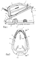
- the figure 1 and 2 represent an ironing apparatus, of the steam generator type, conventionally comprising an iron 1 to be ironed resting on a portable base 2 incorporating, in a manner known per se, a vessel for producing steam under pressure, not shown in the figures, the base 2 being electrically powered by means of a cable 24.
- the iron 1 comprises a heating soleplate surmounted by a one-piece plastic body incorporating a handle 11, the latter extending towards the rear of the iron by two arms 12 comprising a rear face constituting the heel of the iron, the body having a portion of cantilever extending between the sole 10 and the heel of the iron.
- the handle 11 is conventionally extended towards the front of the iron by a nose covering the front tip of the sole 10, the iron 1 being connected to the base 2 by a flexible cord 3 incorporating electrical supply wires of the heating soleplate 10 as well as a steam supply duct 10 of the iron soleplate.
- the base 2 has a flat bottom surface 20 intended to rest on a horizontal plane and has a inclined upper surface 21 comprising a recess constituting a location 21A for resting the iron 1, this location 21A having an inclined plane bottom of the order of 30 ° relative to the lower surface 20 and having pads 21 B projecting to heat insulating the base 2 of the sole 10 of the iron.
- the upper surface 21 of the base 2 comprises, in front of the location 21A, a control panel 23 of the apparatus, advantageously arranged in a plane parallel to the plane of the location 21A, and encloses in the space under the location 21, a tank for supplying water to the tank for the production of steam, the tank being provided with a filler door 25.
- the base comprises a stopper 22 disposed at the foot of the location 21A, on which the heel of the iron comes to bear when it is placed on the bottom inclined plane of location 21A.
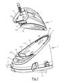
- the stopper 22 has a first protrusion 22A inserted into a cavity 13 formed on a lower face of the cantilevered portion located at the rear of the iron 1 to be ironed.
- the first protrusion 22A extends parallel to the bottom of the location 21A and towards the center of the location 21A, from a raised border of the location 21A, the cavity 13 comprising a return of material 13A coming from to position itself under the protrusion 22A when the iron 1 to be ironed is disposed on the location 21A so as to ensure the vertical immobilization of the rear part of the iron 1 in the location 21A, the protrusion 13A advantageously having a convergent shape with rounded edges to facilitate engagement and ensure centering of the iron on location 21A.
- the buffer 22 also comprises a second protrusion 22B having a shape similar to the first protrusion 22A, this second protrusion 22B being arranged slightly set back from the edge of the location 21A and extending transversely to the first protrusion 22A, upwards, so as to fit into a space 12A formed between the two arms 12 and ensure a lateral setting of the iron 1 to iron in the location 21A, in addition to the guidance and maintenance already carried out by the first protrusion 22A.
- the front part of the iron 1 is immobilized on the base 2 by means of a hoop 4 pivotally mounted at the portion of the location 21A receiving the front tip of the sole 10 of the iron, the hoop 4 having advantageously a triangular shape conforming to the contour of the front end of the location 21A.
- the hoop 4 can pivot between a folded position, illustrated on the figures 2 and 6 , in which the hoop 4 is engaged in a receiving groove formed at the edge of the location 21A, being arranged parallel to the upper surface 21 of the base, and a position of immobilization of the iron, illustrated on the figures 1 and 8 , in which the arch 4 bears against the upper surface of the nose of the iron 1, the arch 4 advantageously comprising a flexible portion 40 attached by overmolding in the hollow portion of the arch 4 coming into contact with the body of the iron 1 to iron when the arch 4 is in the immobilization position.
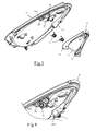
- the hoop 4 is preferably constituted by a plastic part comprising two branches, defining an inverted V, having a lower end passing through an opening 26 formed on the surface upper of the base 2 to be pivotally mounted on an axis 5 disposed inside the base 2, the axis 5 being carried by tabs 27 projecting under the upper surface of the base 2.
- the base 2 comprises return means 6 exerting a torque on the hoop 4 whose direction reverses when passing from an intermediate position, illustrated on the figure 7 , located between the folded position and the immobilization position, the restoring torque bringing the hoop 4 to the folded position when the latter is in an angular position between the folded position and the intermediate position and bringing the hoop 4 to the immobilization position when the latter is in an angular position between the intermediate position and the immobilization position.
- the return means are advantageously constituted by two helical torsion springs 6 arranged near the lower end of the branches of the arch 4, each spring 6 having a first curved end engaging in a hole 28A formed in a support stud 28 protruding under the upper surface 21 of the base and a second curved end engaging in a notch 41 formed at the edge of the leg of the arch 4.
- the notch 41 is formed along the edge of the arch 4 so that the notch 41 is above the line passing through the orifice 28A and the axis 5 of rotation when the arch 4 is is in the folded position, illustrated on the figure 6 , and is below the line d when the arch 4 is in the immobilization position illustrated on the figure 8 , in which the arch 4 advantageously forms an angle of the order of 50 ° with respect to the bottom of the location 21A, the notch 41 being aligned with the line d when the arch 4 occupies an intermediate position, illustrated on the figure 7 , in which the arch advantageously forms an angle of the order of 20 ° with respect to the bottom of the location 21A.
- the arch 4 also comprises a stop 42 which abuts against an edge 26A of the opening 26 to limit the pivoting stroke of the arch 4 in a stop position, not shown in the figures, located slightly beyond the immobilization position.
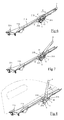
- the user wishes to immobilize the iron 1 to iron on the base 2, he brings the iron 1 to iron on the 21A location by placing the sole 10 on the pads 21 B so that the rear part of the iron 1 to iron is slightly distant from the stopper 22. The user then slightly drag the iron 1 to iron to the stopper 22 so that the first protrusion 22A engages in the cavity 13 formed at the rear of the iron, this slip being favored, or even taking place automatically under the effect of gravity, thanks to the pronounced inclination of the location 21A and the non-stick coating that can be arranged on the pads 21 B.
- the iron 1 to be ironed is then automatically positioned on the stopper 22, under the effect of the guide provided by the insertion of the first protrusion 22A in the cavity 13 and the second protrusion 22B engages in the space 12A formed between the arms 12 of the iron so that the rear portion of the iron 1 to be ironed is wedged laterally on the base 2.
- the return torque exerted by the springs 6 is reversed, the springs 6 then exerting a restoring torque in the direction R 2 which increases progressively as and when as the arch 4 approaches the blocking position in which it abuts against the nose of the iron 1 to iron.
- the hoop 4 is applied against the upper face of the body of the iron 1 and pushing the iron 1 to iron to the stopper 22, so that a perfect immobilization results, without deflection, iron 1 on the base 2, the lifting of the rear part of the iron 1 to be ironed being prevented by the insertion of the protrusion 22A into the cavity 13 of the iron 1 to be ironed while the lifting of the front part of the iron 1 to be ironed is prevented by the presence of the blocking arch 4.
- the user can then transport the device safely by grasping the handle 11 of the iron.
- the hoop 4 pivots under the effect of the couple of springs 6 of return until the abutment 42 at the base of the arch 4 bears against the edge 26A of the opening 26, thus preventing the arch 4 from tilting too far towards the rear of the base 2.
- the user can then grasp the iron 1 to be ironed by the handle 11 so as to move it away from the stopper 22 and to disengage the protrusion 22A of the cavity 13.
- Such an iron locking device on the base of the device thus has the advantage of being both simple design and very ergonomic use.
- the bumper immobilizing the rear part of the iron has the advantage of being bulky and therefore space-saving.
- the cavity receiving the protrusion being disposed on the underside of the body of the iron, it has the advantage of being substantially invisible to the user when the iron rests on its sole. Such a technical solution therefore makes it possible to have a compact device with improved aesthetics.
- the stop of the bow can be arranged in such a way that the stop position of the bow in which the stop abuts on the edge of the opening corresponds to at an immobilization position of the iron in which the hoop is in the immediate vicinity of the iron without affecting the latter.
- the tank for the generation of pressurized steam may be replaced by an instantaneous vaporization chamber, the latter may be arranged in the base or in the iron being connected to a reservoir contained in the base by a water pipe.
Landscapes
- Engineering & Computer Science (AREA)
- Textile Engineering (AREA)
- Health & Medical Sciences (AREA)
- Public Health (AREA)
- Irons (AREA)
- Cookers (AREA)
- Details Of Rigid Or Semi-Rigid Containers (AREA)
- Footwear And Its Accessory, Manufacturing Method And Apparatuses (AREA)
- Clamps And Clips (AREA)
Applications Claiming Priority (1)
| Application Number | Priority Date | Filing Date | Title |
|---|---|---|---|
| FR1452468A FR3018830B1 (fr) | 2014-03-24 | 2014-03-24 | Appareil electromenager comportant un fer a repasser et une base portative comprenant un emplacement pour poser le fer a repasser |
Publications (2)
| Publication Number | Publication Date |
|---|---|
| EP2933372A1 true EP2933372A1 (de) | 2015-10-21 |
| EP2933372B1 EP2933372B1 (de) | 2019-02-20 |
Family
ID=51014454
Family Applications (1)
| Application Number | Title | Priority Date | Filing Date |
|---|---|---|---|
| EP15159289.6A Active EP2933372B1 (de) | 2014-03-24 | 2015-03-16 | Elektrohaushaltsgerät, das ein bügeleisen und eine tragbare basis umfasst, die einen abstellort für das bügeleisen beinhaltet |
Country Status (6)
| Country | Link |
|---|---|
| EP (1) | EP2933372B1 (de) |
| CN (1) | CN104947401B (de) |
| ES (1) | ES2716679T3 (de) |
| FR (1) | FR3018830B1 (de) |
| RU (1) | RU2680369C2 (de) |
| TR (1) | TR201903822T4 (de) |
Cited By (1)
| Publication number | Priority date | Publication date | Assignee | Title |
|---|---|---|---|---|
| WO2018075192A1 (en) * | 2016-10-19 | 2018-04-26 | Spectrum Brands, Inc. | Portable steam generator base for iron |
Families Citing this family (3)
| Publication number | Priority date | Publication date | Assignee | Title |
|---|---|---|---|---|
| FR3060031B1 (fr) * | 2016-12-13 | 2019-12-13 | Seb S.A. | Fer a vapeur comportant un circuit de distribution de vapeur menage dans un corps en contact thermique avec une surface de repassage |
| FR3065232B1 (fr) * | 2017-04-12 | 2019-04-19 | Seb S.A. | Appareil de repassage |
| CN107489011B (zh) * | 2017-08-25 | 2019-08-09 | 广东美的环境电器制造有限公司 | 底座组件和熨烫电器 |
Citations (4)
| Publication number | Priority date | Publication date | Assignee | Title |
|---|---|---|---|---|
| EP0682142A2 (de) * | 1994-05-10 | 1995-11-15 | Black & Decker Inc. | Bügeleisen mit integriertem Ständer und Stabilisierungsverfahren |
| EP1612321A1 (de) * | 2004-07-02 | 2006-01-04 | Seb S.A. | Bügelvorrichtung umfassend ein Bügeleisen und einen tragbaren, mit einer Schutzhülle versehenden Stand |
| FR2874628A1 (fr) | 2004-09-02 | 2006-03-03 | Seb Sa | Appareil de repassage comportant un fer a repasser et une base portative |
| DE102011080152A1 (de) * | 2011-05-31 | 2012-12-06 | BSH Bosch und Siemens Hausgeräte GmbH | Basis für eine Bügelstation und Bügelstation |
Family Cites Families (5)
| Publication number | Priority date | Publication date | Assignee | Title |
|---|---|---|---|---|
| CN201627099U (zh) * | 2010-01-28 | 2010-11-10 | 广东新宝电器股份有限公司 | 带蒸汽座的电烫斗 |
| HK1150724A2 (en) * | 2010-11-26 | 2011-12-30 | Ascentway Ind Ltd | A steam ironing system |
| CN202359423U (zh) * | 2011-12-02 | 2012-08-01 | 广东新宝电器股份有限公司 | 蒸汽烫斗的锁定结构 |
| CN102965897B (zh) * | 2012-12-04 | 2015-03-25 | 张建炜 | 一种自动充水的电烫斗 |
| CN103614893B (zh) * | 2013-11-19 | 2016-01-13 | 宁波凯波集团有限公司 | 便于搬运的分体式蒸汽熨斗及其锁定结构 |
-
2014
- 2014-03-24 FR FR1452468A patent/FR3018830B1/fr active Active
-
2015
- 2015-03-16 TR TR2019/03822T patent/TR201903822T4/tr unknown
- 2015-03-16 ES ES15159289T patent/ES2716679T3/es active Active
- 2015-03-16 EP EP15159289.6A patent/EP2933372B1/de active Active
- 2015-03-17 CN CN201510115487.2A patent/CN104947401B/zh active Active
- 2015-03-20 RU RU2015109783A patent/RU2680369C2/ru active
Patent Citations (4)
| Publication number | Priority date | Publication date | Assignee | Title |
|---|---|---|---|---|
| EP0682142A2 (de) * | 1994-05-10 | 1995-11-15 | Black & Decker Inc. | Bügeleisen mit integriertem Ständer und Stabilisierungsverfahren |
| EP1612321A1 (de) * | 2004-07-02 | 2006-01-04 | Seb S.A. | Bügelvorrichtung umfassend ein Bügeleisen und einen tragbaren, mit einer Schutzhülle versehenden Stand |
| FR2874628A1 (fr) | 2004-09-02 | 2006-03-03 | Seb Sa | Appareil de repassage comportant un fer a repasser et une base portative |
| DE102011080152A1 (de) * | 2011-05-31 | 2012-12-06 | BSH Bosch und Siemens Hausgeräte GmbH | Basis für eine Bügelstation und Bügelstation |
Cited By (2)
| Publication number | Priority date | Publication date | Assignee | Title |
|---|---|---|---|---|
| WO2018075192A1 (en) * | 2016-10-19 | 2018-04-26 | Spectrum Brands, Inc. | Portable steam generator base for iron |
| US10443185B2 (en) | 2016-10-19 | 2019-10-15 | Spectrum Brands, Inc. | Portable steam generator base for iron |
Also Published As
| Publication number | Publication date |
|---|---|
| EP2933372B1 (de) | 2019-02-20 |
| RU2015109783A3 (de) | 2018-08-02 |
| TR201903822T4 (tr) | 2019-04-22 |
| CN104947401B (zh) | 2019-04-19 |
| RU2015109783A (ru) | 2016-10-10 |
| FR3018830B1 (fr) | 2016-05-13 |
| RU2680369C2 (ru) | 2019-02-19 |
| CN104947401A (zh) | 2015-09-30 |
| ES2716679T3 (es) | 2019-06-14 |
| FR3018830A1 (fr) | 2015-09-25 |
Similar Documents
| Publication | Publication Date | Title |
|---|---|---|
| EP1709235B1 (de) | Bügelvorrichtung mit eisen und tragbarem untersatz | |
| EP3421658B1 (de) | Dampfbügel- und/oder entknitterungsgerät, das ein bügelbrett umfasst, das in verschiedenen neigungswinkeln festgestellt werden kann | |
| FR2929354A1 (fr) | Dispositif de verrouillage pour canne telescopique et appareil muni d'un tel dispositif de verrouillage | |
| EP2933372B1 (de) | Elektrohaushaltsgerät, das ein bügeleisen und eine tragbare basis umfasst, die einen abstellort für das bügeleisen beinhaltet | |
| EP3696314B1 (de) | Wäschebehandlungsgerät mit dampf, das eine halterungsvorrichtung umfasst | |
| CH644501A5 (fr) | Chaussure de ski. | |
| EP2933371B1 (de) | Elektrisches haushaltsgerät für den handbetrieb, das eine vorrichtung zum bügeln und/oder entknittern enthält, und tragbare basis | |
| EP3581702B1 (de) | Wäschebehandlungsgerät mit dampf, das eine halterungsvorrichtung umfasst | |
| EP3002363B1 (de) | Elektrohaushaltsgerät, das ein bügeleisen und eine tragbare basis umfasst, die einen abstellort für das bügeleisen beinhaltet | |
| EP3404138B1 (de) | Elektrohaushaltsgerät, das ein bügeleisen und eine tragbare basis umfasst | |
| EP2087164B1 (de) | Bügeleisen mit einer verbesserten kabelführungsvorrichtung | |
| EP1764439A1 (de) | Bügeleisen mit einer verbesserten Vorrichtung zur Kabelzuführung | |
| EP3581700B1 (de) | Wäschebehandlungsgerät, das eine basis mit einem abnehmbaren behälter umfasst | |
| EP3581704A1 (de) | Wäschebehandlungsgerät mit dampf, das ein bügelbrett umfasst | |
| WO2011012803A1 (fr) | Appareil de repassage comportant un fer a repasser et une base generatrice de vapeur muni d'un dispositif guide-cordon | |
| EP3754099A1 (de) | Bügelvorrichtung mit einem bügelbrett mit geneigter oberfläche | |
| EP3581703A1 (de) | Wäschebehandlungsgerät mit dampf, das ein bügelbrett umfasst | |
| EP3754097B1 (de) | Bügelvorrichtung mit einem bügelbrett | |
| FR3036121A1 (fr) | Appareil electromenager de repassage comportant un fer a repasser et une base comprenant un emplacement pour poser le fer a repasser | |
| EP3754098B1 (de) | Bügelvorrichtung umfassend einem bügelbrett mit zwei gegenüberliegenden flächen auf die ein zu bügelnder gegenstand platziert werden kann | |
| FR3092593A1 (fr) | Appareil de traitement du linge a la vapeur comportant un dispositif support | |
| WO2023280726A1 (fr) | Appareil électroménager comportant un outil de repassage et/ou défroissage et une base portative reliée à l'outil par un cordon. | |
| EP4273315A1 (de) | Haushaltsgerät mit einem tragegurt | |
| EP4273316A1 (de) | Elektrisches haushaltsgerät mit einem bügeleisen und einer mit einem kabel verbundenen bügeleisenbasis |
Legal Events
| Date | Code | Title | Description |
|---|---|---|---|
| PUAI | Public reference made under article 153(3) epc to a published international application that has entered the european phase |
Free format text: ORIGINAL CODE: 0009012 |
|
| AK | Designated contracting states |
Kind code of ref document: A1 Designated state(s): AL AT BE BG CH CY CZ DE DK EE ES FI FR GB GR HR HU IE IS IT LI LT LU LV MC MK MT NL NO PL PT RO RS SE SI SK SM TR |
|
| AX | Request for extension of the european patent |
Extension state: BA ME |
|
| 17P | Request for examination filed |
Effective date: 20160401 |
|
| RBV | Designated contracting states (corrected) |
Designated state(s): AL AT BE BG CH CY CZ DE DK EE ES FI FR GB GR HR HU IE IS IT LI LT LU LV MC MK MT NL NO PL PT RO RS SE SI SK SM TR |
|
| RAP1 | Party data changed (applicant data changed or rights of an application transferred) |
Owner name: SEB S.A. |
|
| STAA | Information on the status of an ep patent application or granted ep patent |
Free format text: STATUS: EXAMINATION IS IN PROGRESS |
|
| 17Q | First examination report despatched |
Effective date: 20170105 |
|
| GRAP | Despatch of communication of intention to grant a patent |
Free format text: ORIGINAL CODE: EPIDOSNIGR1 |
|
| STAA | Information on the status of an ep patent application or granted ep patent |
Free format text: STATUS: GRANT OF PATENT IS INTENDED |
|
| INTG | Intention to grant announced |
Effective date: 20180914 |
|
| GRAS | Grant fee paid |
Free format text: ORIGINAL CODE: EPIDOSNIGR3 |
|
| GRAA | (expected) grant |
Free format text: ORIGINAL CODE: 0009210 |
|
| STAA | Information on the status of an ep patent application or granted ep patent |
Free format text: STATUS: THE PATENT HAS BEEN GRANTED |
|
| AK | Designated contracting states |
Kind code of ref document: B1 Designated state(s): AL AT BE BG CH CY CZ DE DK EE ES FI FR GB GR HR HU IE IS IT LI LT LU LV MC MK MT NL NO PL PT RO RS SE SI SK SM TR |
|
| REG | Reference to a national code |
Ref country code: GB Ref legal event code: FG4D Free format text: NOT ENGLISH |
|
| REG | Reference to a national code |
Ref country code: CH Ref legal event code: EP |
|
| REG | Reference to a national code |
Ref country code: DE Ref legal event code: R096 Ref document number: 602015024717 Country of ref document: DE |
|
| REG | Reference to a national code |
Ref country code: AT Ref legal event code: REF Ref document number: 1098326 Country of ref document: AT Kind code of ref document: T Effective date: 20190315 |
|
| REG | Reference to a national code |
Ref country code: IE Ref legal event code: FG4D Free format text: LANGUAGE OF EP DOCUMENT: FRENCH |
|
| REG | Reference to a national code |
Ref country code: ES Ref legal event code: FG2A Ref document number: 2716679 Country of ref document: ES Kind code of ref document: T3 Effective date: 20190614 |
|
| REG | Reference to a national code |
Ref country code: NL Ref legal event code: MP Effective date: 20190220 |
|
| REG | Reference to a national code |
Ref country code: LT Ref legal event code: MG4D |
|
| PG25 | Lapsed in a contracting state [announced via postgrant information from national office to epo] |
Ref country code: FI Free format text: LAPSE BECAUSE OF FAILURE TO SUBMIT A TRANSLATION OF THE DESCRIPTION OR TO PAY THE FEE WITHIN THE PRESCRIBED TIME-LIMIT Effective date: 20190220 Ref country code: NO Free format text: LAPSE BECAUSE OF FAILURE TO SUBMIT A TRANSLATION OF THE DESCRIPTION OR TO PAY THE FEE WITHIN THE PRESCRIBED TIME-LIMIT Effective date: 20190520 Ref country code: LT Free format text: LAPSE BECAUSE OF FAILURE TO SUBMIT A TRANSLATION OF THE DESCRIPTION OR TO PAY THE FEE WITHIN THE PRESCRIBED TIME-LIMIT Effective date: 20190220 Ref country code: NL Free format text: LAPSE BECAUSE OF FAILURE TO SUBMIT A TRANSLATION OF THE DESCRIPTION OR TO PAY THE FEE WITHIN THE PRESCRIBED TIME-LIMIT Effective date: 20190220 Ref country code: PT Free format text: LAPSE BECAUSE OF FAILURE TO SUBMIT A TRANSLATION OF THE DESCRIPTION OR TO PAY THE FEE WITHIN THE PRESCRIBED TIME-LIMIT Effective date: 20190620 Ref country code: SE Free format text: LAPSE BECAUSE OF FAILURE TO SUBMIT A TRANSLATION OF THE DESCRIPTION OR TO PAY THE FEE WITHIN THE PRESCRIBED TIME-LIMIT Effective date: 20190220 |
|
| PG25 | Lapsed in a contracting state [announced via postgrant information from national office to epo] |
Ref country code: LV Free format text: LAPSE BECAUSE OF FAILURE TO SUBMIT A TRANSLATION OF THE DESCRIPTION OR TO PAY THE FEE WITHIN THE PRESCRIBED TIME-LIMIT Effective date: 20190220 Ref country code: RS Free format text: LAPSE BECAUSE OF FAILURE TO SUBMIT A TRANSLATION OF THE DESCRIPTION OR TO PAY THE FEE WITHIN THE PRESCRIBED TIME-LIMIT Effective date: 20190220 Ref country code: BG Free format text: LAPSE BECAUSE OF FAILURE TO SUBMIT A TRANSLATION OF THE DESCRIPTION OR TO PAY THE FEE WITHIN THE PRESCRIBED TIME-LIMIT Effective date: 20190520 Ref country code: IS Free format text: LAPSE BECAUSE OF FAILURE TO SUBMIT A TRANSLATION OF THE DESCRIPTION OR TO PAY THE FEE WITHIN THE PRESCRIBED TIME-LIMIT Effective date: 20190620 Ref country code: GR Free format text: LAPSE BECAUSE OF FAILURE TO SUBMIT A TRANSLATION OF THE DESCRIPTION OR TO PAY THE FEE WITHIN THE PRESCRIBED TIME-LIMIT Effective date: 20190521 Ref country code: HR Free format text: LAPSE BECAUSE OF FAILURE TO SUBMIT A TRANSLATION OF THE DESCRIPTION OR TO PAY THE FEE WITHIN THE PRESCRIBED TIME-LIMIT Effective date: 20190220 |
|
| REG | Reference to a national code |
Ref country code: AT Ref legal event code: MK05 Ref document number: 1098326 Country of ref document: AT Kind code of ref document: T Effective date: 20190220 |
|
| PG25 | Lapsed in a contracting state [announced via postgrant information from national office to epo] |
Ref country code: EE Free format text: LAPSE BECAUSE OF FAILURE TO SUBMIT A TRANSLATION OF THE DESCRIPTION OR TO PAY THE FEE WITHIN THE PRESCRIBED TIME-LIMIT Effective date: 20190220 Ref country code: DK Free format text: LAPSE BECAUSE OF FAILURE TO SUBMIT A TRANSLATION OF THE DESCRIPTION OR TO PAY THE FEE WITHIN THE PRESCRIBED TIME-LIMIT Effective date: 20190220 Ref country code: SK Free format text: LAPSE BECAUSE OF FAILURE TO SUBMIT A TRANSLATION OF THE DESCRIPTION OR TO PAY THE FEE WITHIN THE PRESCRIBED TIME-LIMIT Effective date: 20190220 Ref country code: AL Free format text: LAPSE BECAUSE OF FAILURE TO SUBMIT A TRANSLATION OF THE DESCRIPTION OR TO PAY THE FEE WITHIN THE PRESCRIBED TIME-LIMIT Effective date: 20190220 Ref country code: CZ Free format text: LAPSE BECAUSE OF FAILURE TO SUBMIT A TRANSLATION OF THE DESCRIPTION OR TO PAY THE FEE WITHIN THE PRESCRIBED TIME-LIMIT Effective date: 20190220 Ref country code: RO Free format text: LAPSE BECAUSE OF FAILURE TO SUBMIT A TRANSLATION OF THE DESCRIPTION OR TO PAY THE FEE WITHIN THE PRESCRIBED TIME-LIMIT Effective date: 20190220 |
|
| REG | Reference to a national code |
Ref country code: CH Ref legal event code: PL |
|
| REG | Reference to a national code |
Ref country code: DE Ref legal event code: R097 Ref document number: 602015024717 Country of ref document: DE |
|
| PG25 | Lapsed in a contracting state [announced via postgrant information from national office to epo] |
Ref country code: LU Free format text: LAPSE BECAUSE OF NON-PAYMENT OF DUE FEES Effective date: 20190316 Ref country code: SM Free format text: LAPSE BECAUSE OF FAILURE TO SUBMIT A TRANSLATION OF THE DESCRIPTION OR TO PAY THE FEE WITHIN THE PRESCRIBED TIME-LIMIT Effective date: 20190220 Ref country code: PL Free format text: LAPSE BECAUSE OF FAILURE TO SUBMIT A TRANSLATION OF THE DESCRIPTION OR TO PAY THE FEE WITHIN THE PRESCRIBED TIME-LIMIT Effective date: 20190220 |
|
| REG | Reference to a national code |
Ref country code: BE Ref legal event code: MM Effective date: 20190331 |
|
| PLBE | No opposition filed within time limit |
Free format text: ORIGINAL CODE: 0009261 |
|
| STAA | Information on the status of an ep patent application or granted ep patent |
Free format text: STATUS: NO OPPOSITION FILED WITHIN TIME LIMIT |
|
| PG25 | Lapsed in a contracting state [announced via postgrant information from national office to epo] |
Ref country code: AT Free format text: LAPSE BECAUSE OF FAILURE TO SUBMIT A TRANSLATION OF THE DESCRIPTION OR TO PAY THE FEE WITHIN THE PRESCRIBED TIME-LIMIT Effective date: 20190220 Ref country code: MC Free format text: LAPSE BECAUSE OF FAILURE TO SUBMIT A TRANSLATION OF THE DESCRIPTION OR TO PAY THE FEE WITHIN THE PRESCRIBED TIME-LIMIT Effective date: 20190220 |
|
| 26N | No opposition filed |
Effective date: 20191121 |
|
| PG25 | Lapsed in a contracting state [announced via postgrant information from national office to epo] |
Ref country code: CH Free format text: LAPSE BECAUSE OF NON-PAYMENT OF DUE FEES Effective date: 20190331 Ref country code: LI Free format text: LAPSE BECAUSE OF NON-PAYMENT OF DUE FEES Effective date: 20190331 Ref country code: IE Free format text: LAPSE BECAUSE OF NON-PAYMENT OF DUE FEES Effective date: 20190316 |
|
| PG25 | Lapsed in a contracting state [announced via postgrant information from national office to epo] |
Ref country code: BE Free format text: LAPSE BECAUSE OF NON-PAYMENT OF DUE FEES Effective date: 20190331 Ref country code: SI Free format text: LAPSE BECAUSE OF FAILURE TO SUBMIT A TRANSLATION OF THE DESCRIPTION OR TO PAY THE FEE WITHIN THE PRESCRIBED TIME-LIMIT Effective date: 20190220 |
|
| PG25 | Lapsed in a contracting state [announced via postgrant information from national office to epo] |
Ref country code: MT Free format text: LAPSE BECAUSE OF FAILURE TO SUBMIT A TRANSLATION OF THE DESCRIPTION OR TO PAY THE FEE WITHIN THE PRESCRIBED TIME-LIMIT Effective date: 20190220 |
|
| PG25 | Lapsed in a contracting state [announced via postgrant information from national office to epo] |
Ref country code: CY Free format text: LAPSE BECAUSE OF FAILURE TO SUBMIT A TRANSLATION OF THE DESCRIPTION OR TO PAY THE FEE WITHIN THE PRESCRIBED TIME-LIMIT Effective date: 20190220 |
|
| PG25 | Lapsed in a contracting state [announced via postgrant information from national office to epo] |
Ref country code: HU Free format text: LAPSE BECAUSE OF FAILURE TO SUBMIT A TRANSLATION OF THE DESCRIPTION OR TO PAY THE FEE WITHIN THE PRESCRIBED TIME-LIMIT; INVALID AB INITIO Effective date: 20150316 |
|
| PG25 | Lapsed in a contracting state [announced via postgrant information from national office to epo] |
Ref country code: MK Free format text: LAPSE BECAUSE OF FAILURE TO SUBMIT A TRANSLATION OF THE DESCRIPTION OR TO PAY THE FEE WITHIN THE PRESCRIBED TIME-LIMIT Effective date: 20190220 |
|
| P01 | Opt-out of the competence of the unified patent court (upc) registered |
Effective date: 20230517 |
|
| PGFP | Annual fee paid to national office [announced via postgrant information from national office to epo] |
Ref country code: DE Payment date: 20240307 Year of fee payment: 10 Ref country code: GB Payment date: 20240325 Year of fee payment: 10 |
|
| PGFP | Annual fee paid to national office [announced via postgrant information from national office to epo] |
Ref country code: TR Payment date: 20240306 Year of fee payment: 10 Ref country code: IT Payment date: 20240312 Year of fee payment: 10 Ref country code: FR Payment date: 20240325 Year of fee payment: 10 |
|
| PGFP | Annual fee paid to national office [announced via postgrant information from national office to epo] |
Ref country code: ES Payment date: 20240405 Year of fee payment: 10 |