EP2933362A1 - Ring-traveler system of ring spinning machine - Google Patents
Ring-traveler system of ring spinning machine Download PDFInfo
- Publication number
- EP2933362A1 EP2933362A1 EP15161587.9A EP15161587A EP2933362A1 EP 2933362 A1 EP2933362 A1 EP 2933362A1 EP 15161587 A EP15161587 A EP 15161587A EP 2933362 A1 EP2933362 A1 EP 2933362A1
- Authority
- EP
- European Patent Office
- Prior art keywords
- ring
- traveler
- recess
- deposit
- recesses
- Prior art date
- Legal status (The legal status is an assumption and is not a legal conclusion. Google has not performed a legal analysis and makes no representation as to the accuracy of the status listed.)
- Granted
Links
Images


Classifications
-
- D—TEXTILES; PAPER
- D01—NATURAL OR MAN-MADE THREADS OR FIBRES; SPINNING
- D01H—SPINNING OR TWISTING
- D01H7/00—Spinning or twisting arrangements
- D01H7/02—Spinning or twisting arrangements for imparting permanent twist
- D01H7/52—Ring-and-traveller arrangements
- D01H7/60—Rings or travellers; Manufacture thereof not otherwise provided for ; Cleaning means for rings
- D01H7/602—Rings
Definitions
- the present invention relates to a ring-traveler system of a ring spinning machine, and in particular, to a ring-traveler system of a ring spinning machine without liquid lubrication.
- Japanese Laid-Open Patent Publication No. 2014-29045 and Japanese Laid-Open Patent Publication No. 2014-29046 disclose a ring-traveler system of a ring spinning machine, which improves a friction reduction effect and keeps the friction reduction effect longer without using liquid lubrication as compared to conventional articles.
- a concave portion having a depth of 0.1 to 20 ⁇ m and a planar portion having a width of 1 to 250 ⁇ m are alternately formed on a sliding surface of a ring on which a traveler slides when the traveler travels.
- the "ring spinning machine” refers to a ring spinning machine, a ring twisting machine, or the like that includes a ring supported by a ring rail to rise and fall and a traveler sliding on the ring, and winds a yarn via the traveler.
- the "concave portion” includes a groove, and a recess surrounded by a plane. According to this configuration, when the traveler slides, air around the concave portion brings a wedge effect, and a friction reduction effect is obtained. Moreover, since the traveler slides on the planar portion, there is no wear of the concave portion.
- Japanese Laid-Open Patent Publication No. 2014-29045 describes that preferably, the concave portion is a circular recess, the diameter of the recess is 5 to 50 ⁇ m, the depth of the recess is 1 to 10 ⁇ m, and the distance between the adjacent recesses is 10 to 100 ⁇ m.
- the document describes that when the concave portion is the circular recess, and the diameter and the depth of the recess, and the distance between the adjacent recesses fall in the above-mentioned ranges, a good friction reduction effect in addition to the wedge effect is obtained because wear powders and other foreign substances are discharged from the sliding interface between the ring and the traveler.
- Japanese Laid-Open Patent Publication No. 2014-29046 400 or more concave portions per centimeter are formed on a sliding surface of a ring on which a traveler slides when the traveler travels.
- Japanese Laid-Open Patent Publication No. 2014-29046 describes that since a fiber film enters the concave portions on the sliding surface of the ring-traveler system to improve the adhesive force of the film and to prevent the fiber film from peeling off, the friction reduction effect caused by lubrication of the fiber film maintains reduced traveling resistance of the traveler.
- Japanese Laid-Open Patent Publication No. 2014-29045 discloses the relationship between the traveling distance of the traveler of less than 9000 km and the traveling resistance, and describes that the traveling resistance in the example is smaller than that of the commercial article, and the friction reduction effect is sustained.
- the traveling resistance increases and replacement of the traveler becomes necessary.
- Japanese Laid-Open Patent Publication No. 2014-29046 discloses that micro-cracks formed on a surface of a hard chromium plating layer are used as concave portions.
- the formation of the micro-cracks brings about the possibility of negatively affecting the durability of the hard chromium plating layer.
- the document discloses that grooves or recesses processed on the surface of the ring or the traveler are used as concave portions.
- the area of a planar portion where no groove or recess is formed becomes extremely small. Since this leads to early wear of the grooves or recesses, the friction reduction effect cannot be sustained.
- a first aspect of the present invention provides a ring-traveler system of a ring spinning machine.
- a circular recess is formed on a sliding surface of a ring on which a traveler slides when the traveler travels.
- the depth of the recess is 0.5 to 8 ⁇ m.
- the diameter of the recess is 5 to 30 ⁇ m.
- the area ratio of the recess is 5 to 16%.
- "Circular” is not limited to a perfect circle, and may be an ellipse having an ellipticity of 0.8 or more.
- the "area ratio" is a value represented by a percentage of the area of all the recesses in the area of the entire sliding surface of the ring on which the traveler slides.
- a ring 11 constituting the ring-traveler system includes a flange 11a having a T-shaped cross section, and a traveler 12 is formed having a C-shaped cross section.
- the ring 11 is formed of a bearing steel.
- a plating layer 13 is formed on a surface of the flange 11a.
- the plating layer 13 is formed by being plated with chromium.
- the plating layer 13 has a thickness of about 10 to 20 ⁇ m.
- the plating layer 13 is a sliding surface of the ring 11 on which the traveler 12 slides when the traveler 12 travels.
- a surface texture having a periodic structure 14 is formed on the plating layer 13 on an inner peripheral surface of the flange 11a.
- the periodic structure 14 is configured by arranging circular recesses 15 at predetermined intervals.
- the depth of each recess 15 is 0.5 to 8 ⁇ m, preferably, 1 to 5 ⁇ m, more preferably, 2 to 4 ⁇ m.
- the diameter of the recess 15 is 5 to 30 ⁇ m, preferably, 8 to 25 ⁇ m, more preferably, 10 to 20 ⁇ m.
- the area ratio of the recesses 15 is 5 to 16%.
- the area ratio is a value represented by a percentage of the area of all the recesses 15 in the area of the entire sliding surface of the ring 11 on which the traveler 12 slides.
- the recesses 15 are formed, for example, by irradiating locations where the recesses 15 of the ring 11 are to be formed with a femtosecond pulsed laser or a high-power nano-pulsed laser.
- a yarn Y is sent out from a draft part not illustrated, and then is wound around a high-speed rotating bobbin not illustrated through the traveler 12.
- the maximum rotating speed of a spindle in the normal spinning operation of the ring spinning machine is about 25000 rpm.
- the traveler 12 travels on the flange 11a by the winding tension of the yarn Y.
- the traveling posture of the traveler 12 slightly varies depending on the rotating speed.
- the traveler 12 travels on the ring 11 while abutting on an inner lower portion of the flange 11a.
- the surface texture having the periodic structure 14 is formed on the sliding surface of the ring 11 on which the traveler 12 slides when the traveler 12 travels.
- the periodic structure 14 is formed such that the recesses 15 satisfy predetermined conditions. This decreases the traveling resistance of the traveler 12, because a yarn component deposit is formed in the recesses 15 when the traveler 12 slides.
- the recesses 15 satisfy the requirement that the area ratio is 5 to 16%.
- the surface texture of the ring 11 causes yarn component-derived carbon to be formed as a thin deposit 16 on the entire sliding surface.
- the thin deposit 16 is formed on the entire sliding surface and then, acts as a lubricating film. Since this prevents metal-to metal contact between the ring 11 and the traveler 12, wear of the traveler 12 reduces. As a result, since the friction reduction effect is sustained long, the traveler 12 becomes difficult to wear.
- Fig. 3A and Fig. 3B exaggeratedly illustrate irregularity of the sliding surface of the ring 11 on which the traveler 12 slides.
- the deposit 16 is formed on only a portion of the sliding surface, and the deposit 16 becomes thick.
- the metal-to metal contact between the ring 11 and the traveler 12 occurs on a portion where no deposit is formed.
- the friction increases and the wear of the traveler 12 advances. Therefore, the friction reduction effect is not sustained longer as compared to the case where yarn component-derived carbon is formed as the thin deposit 16 on the entire sliding surface.
- the bearing steel ring 11 formed by plating the surface of the flange 11a with Cr was used. Moreover, a surface texture having the periodic structure 14 was formed on the sliding surface of the ring 11 on which the traveler 12 slides.
- the surface texture was formed on the ring 11 by using a high-power nano-pulsed laser (HIPPO 355-5W manufactured by Spectra-Physics KK., with a laser having a wavelength of 335 nm).
- HIPPO 355-5W manufactured by Spectra-Physics KK.
- pulse energy was set to 86 uJ
- pulse time was set to 12 ns.
- the ring was fixed to a jig in air, the rotating speed was set to 50°/sec, and the ring was rotated 25 times.
- the diameter and the depth of each hole of the surface texture formed by the laser irradiation were 20 ⁇ m and 2 ⁇ m, respectively.
- the surface texture was formed at intervals of 70 ⁇ m in the ring circumferential direction and at intervals of 60 ⁇ m in the axial direction.
- the processing time per ring was about 160 seconds.
- Various textures were formed by changing other laser irradiation conditions than the above. An example of the conditions is shown in Table 1.
- the number of the holes per centimeter was 111 to 125. (Table 1) Diameter ( ⁇ m) Area Ratio (%) Depth ( ⁇ m) Sample 1 10 1.6 2 Sample 2 10 8.7 2 Sample 3 20 6.4 4 Sample 4 20 12.6 4
- Sample 1 is a conventional article disclosed in Japanese Laid-Open Patent Publication No. 2014-29045 .
- Sample 2 to Sample 4 are articles according to the present invention.
- a ring-traveler system using the ring 11 having the surface texture formed thereon (hereinafter may also be referred to as a surface textured article) and a ring-traveler system using a commercial ring having no surface texture formed thereon were constituted. Then, a spinning test was performed until the traveling distance reached 25000 km, and the relationship between the traveling resistance and the traveling distance was examined. The spinning test was performed by increasing the rpm in stages from 15000 to 21000 rpm until the traveling distance of the traveler 12 reached 1400 km, and by keeping high-speed rotation of 22000 rpm after the traveling distance reached 1600 km. Concerning the traveling resistance, a co-rotating force applied from the traveler 12 to the ring 11 was measured using a load cell in the state where the ring 11 was rotationally supported.
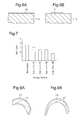
- Fig. 4 illustrates the results of the relationship between the traveling resistance and the traveling distance.
- the traveling resistance of the ring 11 having the surface texture with the periodic structure 14 formed thereon is smaller than the traveling resistance of the commercial ring.
- the traveling resistance of Sample 1 (conventional article) that is the ring 11 having the surface texture but does not satisfy the configuration requirement that the area ratio is 5 to 16% according to the present invention increased to 18[gf] to 19[gf] when the traveling distance reached 17000 km.
- the spinning test was continued until the traveling distance of the traveler 12 reached 25000 km. Then, wear of the traveler 12 was evaluated at a time point when the traveling distance reached 25000 km. Moreover, sliding surfaces of the surface textured article and the commercial ring after spinning and cross sections near the sliding surfaces were observed using a scanning electron microscope (SEM). Moreover, carbon on the sliding surfaces was analyzed using an electron probe microanalyzer (EPMA).
- SEM scanning electron microscope
- EPMA electron probe microanalyzer
- Fig. 5A and Fig. 5B are schematic views illustrating analysis results of the EPMA.
- Fig. 5A illustrates the analysis results of the sliding surface of the surface textured article according to the present invention
- Fig. 5B illustrates the analysis results of the sliding surface of the ring having no surface texture formed thereon.
- portions where dots are present represent locations where the deposit 16 has adhered. As the number of the dots per unit area is larger, the deposit 16 is thicker.
- the thin carbon deposit 16 present on the entire sliding surface was detected, and the thick and highly-concentrated deposit 16 present on the portions of the recesses 15 was detected.
- the deposit 16 adhered to only a portion of the sliding surface, and the deposit 16 was thicker in many portions than the deposit 16 in the article according to the present invention.
- the deposit 16 is considered to have been formed by wear powders of the yarn Y that are generated by sliding of the traveler 12 and the yarn Y and enter the sliding surface of the ring 11 on which the traveler 12 slides.
- a main component of the yarn is cellulose.
- an organic component-derived fluorescent component was analyzed using the EPMA.
- the deposit was analyzed by Raman analysis.
- an amorphous carbon component-derived spectrum was detected on the sliding surface that is glossier than the recesses 15.
- the amorphous carbon component-derived component also contributes to the lubricating ability and wear is reduced.
- Fig. 6A illustrates the deposit 16 formed on the sliding surface of the surface textured article
- Fig. 6B illustrates the deposit 16 formed on the sliding surface having no surface texture formed thereon.
- the deposit 16 illustrated in Fig. 6B is thicker than the deposit 16 illustrated in Fig. 6A .
- the thickness of the deposit 16 formed on the sliding surface of the surface textured article was about submicron, that is, less than 1 ⁇ m.
- the thickness of the deposit 16 on the sliding surface having no surface texture formed thereon was for example, about 2 ⁇ m.
- Wear of the traveler 12 having slid on the surface textured article was evaluated.
- the minimum thickness that remains after the spinning test was used.
- the initial thickness of the traveler 12 was used as a reference value.
- a wear level at which the traveler has no wear was defined as wear level 1.
- a wear level at which the traveler wore to have the thickness half or more of the initial thickness of the traveler 12 was defined as wear level 2.
- a wear level at which the traveler wore to have the thickness less than a half of the initial thickness of the traveler was defined as wear level 3.
- wear levels 4 and 5 were defined, respectively. These stages are stages where the spinning performance of the yarn decreases and the replacement of the traveler 12 is necessary.
- Fig. 7 illustrates the evaluation results.
- An unprocessed article having no texture formed thereon was used as a comparative article.
- the wear level in the unprocessed article was about 4.
- the results of the best wear level of 1.5 to 2 and less wear were obtained.
- Even in the surface textured article when the area ratio was 2%, that is, the area ratio did not satisfy the requirement of 5 to 16%, the wear level was 3.
- the wear level was 3 or more. Therefore, it was confirmed that the diameter of the hole is preferably 8 to 30 ⁇ m. It was also confirmed that the area ratio is also important and is preferably 5 to 16%.
- the present embodiment may be embodied as follows.
- the recesses 15 of different sizes may be present.
- the recesses 15 of different depths may be present.
- the recesses 15 of different sizes and the recesses 15 of different depths may be present.
- the periodic structure 14 is not limited to the configuration where the recesses 15 are arranged on the entire sliding surface at regular intervals in a staggered or lattice-like manner.
- the recesses may be arranged in a partially different manner or in a random manner.
- the periodic structure 14 may be formed on the flange 11 a without forming the plating layer 13. However, when the material of the ring 11 is a material currently used in the commercial article, it is preferable to form the plating layer 13.
- the ring 11 constituting the ring-traveler system is not limited to the configuration of including the flange 11a having a T-shaped cross section, and may include an inclined flange 11a. In this case, a traveler of a shape corresponding to the inclined flange is used as the traveler 12.
- an extremely-short pulsed laser such as a femtosecond pulsed laser, a high-power picosecond pulsed laser, or a nanosecond pulsed laser
- other well-known methods may be applied.
- the periodic structure 14 may be formed on the traveler 12 in place of the ring 11 of the ring-traveler system.
- the area of the periodic structure 14 becomes much smaller than when the periodic structure is formed on the ring 11. For this reason, it is preferable to form the periodic structure 14 on the traveler 12.
- the spinning yarn is not limited to cotton, and may be linen, silk, wool, chemical fiber (nitrocellulose, nylon, vinylon). Among them, cotton and linen are preferable in the point that cotton and linen discharge wear powders most and it is easy to form the deposit 16 on the sliding surface of the ring on which the traveler slides.
- a circular recess is formed on a sliding surface of a ring on which a traveler slides when the traveler travels.
- the depth of the recess is 0.5 to 8 ⁇ m
- the diameter of the recess is 5 to 30 ⁇ m
- the area ratio of the recess is 5 to 16%.
Landscapes
- Engineering & Computer Science (AREA)
- Mechanical Engineering (AREA)
- Textile Engineering (AREA)
- Spinning Or Twisting Of Yarns (AREA)
Abstract

Description
- The present invention relates to a ring-traveler system of a ring spinning machine, and in particular, to a ring-traveler system of a ring spinning machine without liquid lubrication.
- It has been demanded to decrease frictional wear and seizing that affect the performance of the ring-traveler system of the ring spinning machine, while increasing the speed and prolonging the life of the system. To meet the demand, material variation, surface treatment, shape variation, the use of lubrication liquid, and the like have been proposed. In particular, the use of lubrication liquid is effective and relatively inexpensive. However, the passing yarn may be smeared with lubricating oil, and the use of oil leads to frequent maintenance. Thus, lubrication liquid is used for only limited applications such as spinning of woolen yarns.
- Japanese Laid-Open Patent Publication No.
2014-29045 2014-29046 2014-29045 - Moreover, Japanese Laid-Open Patent Publication No.
2014-29045 - In a ring-traveler system of a ring spinning machine described in Japanese Laid-Open Patent Publication No.
2014-29046 2014-29046 - Japanese Laid-Open Patent Publication No.
2014-29045 - Japanese Laid-Open Patent Publication No.
2014-29046 - It is an object of the present invention to provide a ring-traveler system of a ring spinning machine capable of sustaining a friction reduction effect long without using liquid lubrication.
- To achieve the object, a first aspect of the present invention provides a ring-traveler system of a ring spinning machine. A circular recess is formed on a sliding surface of a ring on which a traveler slides when the traveler travels. The depth of the recess is 0.5 to 8 µm. The diameter of the recess is 5 to 30 µm. Moreover, the area ratio of the recess is 5 to 16%. "Circular" is not limited to a perfect circle, and may be an ellipse having an ellipticity of 0.8 or more. The "area ratio" is a value represented by a percentage of the area of all the recesses in the area of the entire sliding surface of the ring on which the traveler slides.
-
-
Fig. 1A is a perspective view illustrating a ring according to an embodiment of the present invention; -
Fig. 1B is a partial perspective view illustrating the ring; -
Fig. 1C is a partial sectional view illustrating the relationship between a traveler and the ring during spinning; -
Fig. 2A is a partial plan view illustrating concave portions; -
Fig. 2B is a partial sectional view illustrating the concave portions; -
Fig. 3A is a schematic view illustrating an effect of the ring according to the present invention; -
Fig. 3B is a schematic view illustrating an effect of a ring that is a conventional article; -
Fig. 4 is a graph illustrating the relationship between traveling resistance and a traveling distance; -
Fig. 5A is a plan view illustrating the state of deposit having adhered to the surface of the ring; -
Fig. 5B is a plan view illustrating the state of deposit having adhered to the surface of the ring having no recess; -
Fig. 6A is a sectional view illustrating the state of deposit having adhered to the surface of the ring; -
Fig. 6B is a sectional view illustrating the state of deposit having adhered to the surface of the ring having no recess; -
Fig. 7 is a view illustrating the relationship between an area ratio and a wear level; -
Fig. 8A is a schematic view illustrating the wear state of the traveler when the ring according to the present invention is used; and -
Fig. 8B is a schematic view illustrating the wear state of the traveler when a ring in a comparative example is used. - Referring to
Figs. 1 to Fig. 8 , an embodiment of a ring-traveler system of a ring spinning machine according to the present invention will now be described. - As illustrated in
Fig. 1A to Fig. 1C , aring 11 constituting the ring-traveler system includes aflange 11a having a T-shaped cross section, and atraveler 12 is formed having a C-shaped cross section. Thering 11 is formed of a bearing steel. As illustrated inFig. 1 B andFig. 1C , aplating layer 13 is formed on a surface of theflange 11a. Theplating layer 13 is formed by being plated with chromium. Theplating layer 13 has a thickness of about 10 to 20 µm. - The
plating layer 13 is a sliding surface of thering 11 on which thetraveler 12 slides when thetraveler 12 travels. In this embodiment, as illustrated inFig. 1C , a surface texture having aperiodic structure 14 is formed on theplating layer 13 on an inner peripheral surface of theflange 11a. As illustrated inFig. 2A and Fig. 2B , theperiodic structure 14 is configured by arrangingcircular recesses 15 at predetermined intervals. The depth of eachrecess 15 is 0.5 to 8 µm, preferably, 1 to 5 µm, more preferably, 2 to 4 µm. The diameter of therecess 15 is 5 to 30 µm, preferably, 8 to 25 µm, more preferably, 10 to 20 µm. The area ratio of therecesses 15 is 5 to 16%. The area ratio is a value represented by a percentage of the area of all therecesses 15 in the area of the entire sliding surface of thering 11 on which thetraveler 12 slides. Therecesses 15 are formed, for example, by irradiating locations where therecesses 15 of thering 11 are to be formed with a femtosecond pulsed laser or a high-power nano-pulsed laser. - Next, effects of the above-mentioned ring-traveler system will be described with reference to
Fig. 1C ,Fig. 3A, and Fig. 3B . - As illustrated in
Fig. 1C , a yarn Y is sent out from a draft part not illustrated, and then is wound around a high-speed rotating bobbin not illustrated through thetraveler 12. The maximum rotating speed of a spindle in the normal spinning operation of the ring spinning machine is about 25000 rpm. Thetraveler 12 travels on theflange 11a by the winding tension of the yarn Y. The traveling posture of thetraveler 12 slightly varies depending on the rotating speed. Thetraveler 12 travels on thering 11 while abutting on an inner lower portion of theflange 11a. - In the ring-traveler system in this embodiment, the surface texture having the
periodic structure 14 is formed on the sliding surface of thering 11 on which thetraveler 12 slides when thetraveler 12 travels. Theperiodic structure 14 is formed such that therecesses 15 satisfy predetermined conditions. This decreases the traveling resistance of thetraveler 12, because a yarn component deposit is formed in therecesses 15 when thetraveler 12 slides. - Moreover, the
recesses 15 satisfy the requirement that the area ratio is 5 to 16%. Thus, as illustrated inFig. 3A , when thetraveler 12 slides, the surface texture of thering 11 causes yarn component-derived carbon to be formed as athin deposit 16 on the entire sliding surface. Thethin deposit 16 is formed on the entire sliding surface and then, acts as a lubricating film. Since this prevents metal-to metal contact between thering 11 and thetraveler 12, wear of thetraveler 12 reduces. As a result, since the friction reduction effect is sustained long, thetraveler 12 becomes difficult to wear.Fig. 3A and Fig. 3B exaggeratedly illustrate irregularity of the sliding surface of thering 11 on which thetraveler 12 slides. - On the other hand, when requirements that the depth of the
recess 15 is 0.5 to 8 µm, the diameter of the recess is 5 to 30 µm, and the area ratio of the recesses is 5 to 16% are not satisfied, as illustrated inFig. 3B , thedeposit 16 is formed on only a portion of the sliding surface, and thedeposit 16 becomes thick. In this case, the metal-to metal contact between thering 11 and thetraveler 12 occurs on a portion where no deposit is formed. As a result, the friction increases and the wear of thetraveler 12 advances. Therefore, the friction reduction effect is not sustained longer as compared to the case where yarn component-derived carbon is formed as thethin deposit 16 on the entire sliding surface. - The bearing
steel ring 11 formed by plating the surface of theflange 11a with Cr was used. Moreover, a surface texture having theperiodic structure 14 was formed on the sliding surface of thering 11 on which thetraveler 12 slides. - The surface texture was formed on the
ring 11 by using a high-power nano-pulsed laser (HIPPO 355-5W manufactured by Spectra-Physics KK., with a laser having a wavelength of 335 nm). As laser irradiation conditions, pulse energy was set to 86 uJ, and pulse time was set to 12 ns. Moreover, the ring was fixed to a jig in air, the rotating speed was set to 50°/sec, and the ring was rotated 25 times. The diameter and the depth of each hole of the surface texture formed by the laser irradiation were 20 µm and 2 µm, respectively. Moreover, the surface texture was formed at intervals of 70 µm in the ring circumferential direction and at intervals of 60 µm in the axial direction. The processing time per ring was about 160 seconds. Various textures were formed by changing other laser irradiation conditions than the above. An example of the conditions is shown in Table 1. The number of the holes per centimeter was 111 to 125.(Table 1) Diameter (µm) Area Ratio (%) Depth (µm) Sample 110 1.6 2 Sample 210 8.7 2 Sample 3 20 6.4 4 Sample 420 12.6 4 - In Table 1,
Sample 1 is a conventional article disclosed inJapanese Laid-Open Patent Publication No. 2014-29045 Sample 2 toSample 4 are articles according to the present invention. - A ring-traveler system using the
ring 11 having the surface texture formed thereon (hereinafter may also be referred to as a surface textured article) and a ring-traveler system using a commercial ring having no surface texture formed thereon were constituted. Then, a spinning test was performed until the traveling distance reached 25000 km, and the relationship between the traveling resistance and the traveling distance was examined. The spinning test was performed by increasing the rpm in stages from 15000 to 21000 rpm until the traveling distance of thetraveler 12 reached 1400 km, and by keeping high-speed rotation of 22000 rpm after the traveling distance reached 1600 km. Concerning the traveling resistance, a co-rotating force applied from thetraveler 12 to thering 11 was measured using a load cell in the state where thering 11 was rotationally supported. -
Fig. 4 illustrates the results of the relationship between the traveling resistance and the traveling distance. As apparent fromFig. 4 , at high-speed rotation spinning after running-in performed until the traveling distance reaches 1400 km, the traveling resistance of thering 11 having the surface texture with theperiodic structure 14 formed thereon is smaller than the traveling resistance of the commercial ring. Thus, the effect of the surface texture was confirmed. Moreover, the traveling resistance of Sample 1 (conventional article) that is thering 11 having the surface texture, but does not satisfy the configuration requirement that the area ratio is 5 to 16% according to the present invention increased to 18[gf] to 19[gf] when the traveling distance reached 17000 km. On the other hand, the traveling resistance ofSample 2 toSample 4, which are articles according to the present invention, almost did not change when the traveling distance exceeded 17000 km. That is, it was confirmed that the article according to the present invention, which satisfies the requirement for the surface texture different from the requirement of the conventional article, can sustain the friction reduction effect longer than the conventional article. - Further, the spinning test was continued until the traveling distance of the
traveler 12 reached 25000 km. Then, wear of thetraveler 12 was evaluated at a time point when the traveling distance reached 25000 km. Moreover, sliding surfaces of the surface textured article and the commercial ring after spinning and cross sections near the sliding surfaces were observed using a scanning electron microscope (SEM). Moreover, carbon on the sliding surfaces was analyzed using an electron probe microanalyzer (EPMA). -
Fig. 5A and Fig. 5B are schematic views illustrating analysis results of the EPMA.Fig. 5A illustrates the analysis results of the sliding surface of the surface textured article according to the present invention, andFig. 5B illustrates the analysis results of the sliding surface of the ring having no surface texture formed thereon. InFig. 5A and Fig. 5B , portions where dots are present represent locations where thedeposit 16 has adhered. As the number of the dots per unit area is larger, thedeposit 16 is thicker. - As illustrated in
Fig. 5A , in the surface textured article, thethin carbon deposit 16 present on the entire sliding surface was detected, and the thick and highly-concentrated deposit 16 present on the portions of therecesses 15 was detected. On the other hand, as illustrated inFig. 5B , in the ring having no surface texture formed thereon, thedeposit 16 adhered to only a portion of the sliding surface, and thedeposit 16 was thicker in many portions than thedeposit 16 in the article according to the present invention. Thedeposit 16 is considered to have been formed by wear powders of the yarn Y that are generated by sliding of thetraveler 12 and the yarn Y and enter the sliding surface of thering 11 on which thetraveler 12 slides. - A main component of the yarn is cellulose. For this reason, it is considered that an organic component-derived fluorescent component was analyzed using the EPMA. The deposit was analyzed by Raman analysis. As a result, in the deposit in the surface textured article, an amorphous carbon component-derived spectrum was detected on the sliding surface that is glossier than the
recesses 15. In addition to the above-mentioned cellulose-derived component, it is considered that the amorphous carbon component-derived component also contributes to the lubricating ability and wear is reduced. -
Fig. 6A illustrates thedeposit 16 formed on the sliding surface of the surface textured article, andFig. 6B illustrates thedeposit 16 formed on the sliding surface having no surface texture formed thereon. Thedeposit 16 illustrated inFig. 6B is thicker than thedeposit 16 illustrated inFig. 6A . Specifically, the thickness of thedeposit 16 formed on the sliding surface of the surface textured article was about submicron, that is, less than 1 µm. On the contrary, the thickness of thedeposit 16 on the sliding surface having no surface texture formed thereon was for example, about 2 µm. - Wear of the
traveler 12 having slid on the surface textured article was evaluated. For the evaluation of the wear of thetraveler 12, the minimum thickness that remains after the spinning test was used. In this case, the initial thickness of thetraveler 12 was used as a reference value. Then, a wear level at which the traveler has no wear was defined aswear level 1. Moreover, a wear level at which the traveler wore to have the thickness half or more of the initial thickness of thetraveler 12 was defined aswear level 2. Moreover, a wear level at which the traveler wore to have the thickness less than a half of the initial thickness of the traveler was defined as wear level 3. Further, according to stages where the wear advanced, wearlevels traveler 12 is necessary. -
Fig. 7 illustrates the evaluation results. An unprocessed article having no texture formed thereon was used as a comparative article. The wear level in the unprocessed article was about 4. On the contrary, in the traveler having slid on the surface textured article, the results of the best wear level of 1.5 to 2 and less wear were obtained. Even in the surface textured article, when the area ratio was 2%, that is, the area ratio did not satisfy the requirement of 5 to 16%, the wear level was 3. Moreover, although not illustrated, in the surface textured article, when the diameter of therecess 15 exceeded 30 µm, the wear level was 3 or more. Therefore, it was confirmed that the diameter of the hole is preferably 8 to 30 µm. It was also confirmed that the area ratio is also important and is preferably 5 to 16%. - The wear state of the
traveler 12 was observed. As a result, when the ring inSample 1 that is the comparative example was used, as illustrated inFig. 8A , aworn portion 20 was formed on the sliding surface of the ring. However, as illustrated inFig. 8B , when therings 11 inSample 2 toSample 4 in the example were used, formed worn portions 20' each were smaller than the wornportion 20 when the ring inSample 1 was used. - According to this embodiment, the following effects can be obtained.
- (1) In the ring-traveler system of the ring spinning machine, the
circular recesses 15 are formed on the sliding surface of thering 11 on which thetraveler 12 slides when thetraveler 12 travels. The depth of therecess 15 is 0.5 to 8 µm, the diameter of therecess 15 is 5 to 30 µm, and the area ratio of therecesses 15 is 5 to 16%. According to this configuration, when thetraveler 12 slides, therecesses 15 cause yarn component-derived carbon to be formed as thethin deposit 16 on the entire sliding surface. Since thedeposit 16 acts as a lubricating film and thus the metal-to metal contact between thering 11 and thetraveler 12 is prevented, wear of thetraveler 12 reduces. Moreover, according to the above-mentioned diameter and area ratio, a sufficiently large area can be ensured in the planer portion between theadjacent recesses 15, that is, the planer portion where norecess 15 is formed. Therefore, the friction reduction effect can be sustained longer without using liquid lubrication than the conventional article. - (2) The diameter of the
recess 15 may be 8 to 25 µm. When the diameter of therecess 15 is too smaller or too larger, due to the relationship with the area ratio, thedeposit 16 that acts as the lubricating film is difficult to become thin and uniform and it becomes difficult to sustain the friction reduction effect long. On the contrary, when the diameter of therecess 15 is 8 to 25 µm, thedeposit 16 is easy to become thin and uniform and it becomes easy to sustain the friction reduction effect long. Moreover, when the diameter of therecess 15 is 10 to 20 µm, it becomes easy to sustain the friction reduction effect still longer. - (3) The depth of the
recess 15 may be 1 to 5 µm. When the depth of therecess 15 is 1 to 5 µm, a good friction reduction effect is obtained. Moreover, when the depth of therecess 15 is 2 to 4 µm, it becomes easy to sustain the friction reduction effect still longer. - The present embodiment may be embodied as follows.
- The
recesses 15 of different sizes may be present. - The
recesses 15 of different depths may be present. - The
recesses 15 of different sizes and therecesses 15 of different depths may be present. - The
periodic structure 14 is not limited to the configuration where therecesses 15 are arranged on the entire sliding surface at regular intervals in a staggered or lattice-like manner. The recesses may be arranged in a partially different manner or in a random manner. - The
periodic structure 14 may be formed on theflange 11 a without forming theplating layer 13. However, when the material of thering 11 is a material currently used in the commercial article, it is preferable to form theplating layer 13. - The
ring 11 constituting the ring-traveler system is not limited to the configuration of including theflange 11a having a T-shaped cross section, and may include aninclined flange 11a. In this case, a traveler of a shape corresponding to the inclined flange is used as thetraveler 12. - As a method of forming the
periodic structure 14 other than the method using an extremely-short pulsed laser such as a femtosecond pulsed laser, a high-power picosecond pulsed laser, or a nanosecond pulsed laser, other well-known methods may be applied. - The
periodic structure 14 may be formed on thetraveler 12 in place of thering 11 of the ring-traveler system. When theperiodic structure 14 is formed on thetraveler 12, the area of theperiodic structure 14 becomes much smaller than when the periodic structure is formed on thering 11. For this reason, it is preferable to form theperiodic structure 14 on thetraveler 12. - The spinning yarn is not limited to cotton, and may be linen, silk, wool, chemical fiber (nitrocellulose, nylon, vinylon). Among them, cotton and linen are preferable in the point that cotton and linen discharge wear powders most and it is easy to form the
deposit 16 on the sliding surface of the ring on which the traveler slides. - In a ring-traveler system of a ring spinning machine, a circular recess is formed on a sliding surface of a ring on which a traveler slides when the traveler travels. The depth of the recess is 0.5 to 8 µm, the diameter of the recess is 5 to 30 µm, and the area ratio of the recess is 5 to 16%.
Claims (4)
- A ring-traveler system of a ring spinning machine being characterized by:a circular recess (15) is formed on a sliding surface of a ring (11) on which a traveler (12) slides when the traveler (12) travels,a depth of the recess (15) is 0.5 to 8 µm,a diameter of the recess (15) is 5 to 30 µm, andan area ratio of the recess (15) is 5 to 16%.
- The ring-traveler system of the ring spinning machine according to claim 1, being characterized in that the diameter of the recess (15) is 8 to 25 µm.
- The ring-traveler system of the ring spinning machine according to claim 1 or 2, being characterized in that the depth of the recess (15) is 1 to 5 µm.
- A ring (11) of a ring spinning machine, being characterized in that
a circular recess (15) is formed on a contact surface with a traveler (12) when the traveler (12) slides, so as to have a periodic structure (14), and
the ring (11) has the periodic structure (14) with
a depth of the recess (15) of 0.5 to 8 µm,
a diameter of the recess (15) of 5 to 30 µm, and
an area ratio of the recess (15) of 5 to 16%.
Applications Claiming Priority (1)
| Application Number | Priority Date | Filing Date | Title |
|---|---|---|---|
| JP2014084872A JP6027998B2 (en) | 2014-04-16 | 2014-04-16 | Ring / traveler system without liquid lubrication of ring spinning machine |
Publications (2)
| Publication Number | Publication Date |
|---|---|
| EP2933362A1 true EP2933362A1 (en) | 2015-10-21 |
| EP2933362B1 EP2933362B1 (en) | 2018-11-21 |
Family
ID=53175250
Family Applications (1)
| Application Number | Title | Priority Date | Filing Date |
|---|---|---|---|
| EP15161587.9A Active EP2933362B1 (en) | 2014-04-16 | 2015-03-30 | Ring-traveler system for ring spinning machine |
Country Status (3)
| Country | Link |
|---|---|
| EP (1) | EP2933362B1 (en) |
| JP (1) | JP6027998B2 (en) |
| CN (1) | CN105002611B (en) |
Cited By (2)
| Publication number | Priority date | Publication date | Assignee | Title |
|---|---|---|---|---|
| EP3599302A1 (en) * | 2018-07-23 | 2020-01-29 | Kabushiki Kaisha Toyota Jidoshokki | Ring/traveler system for ring spinning machine |
| WO2020129079A1 (en) * | 2018-12-18 | 2020-06-25 | Parthassarathy N | Ring-traveller system of a ring spinning machine |
Families Citing this family (1)
| Publication number | Priority date | Publication date | Assignee | Title |
|---|---|---|---|---|
| JP7390969B2 (en) * | 2020-05-12 | 2023-12-04 | 株式会社豊田中央研究所 | Ring for spinning machine and its manufacturing method |
Citations (5)
| Publication number | Priority date | Publication date | Assignee | Title |
|---|---|---|---|---|
| GB1212067A (en) * | 1967-01-31 | 1970-11-11 | Maremont Corp | Improvements in or relating to spinning rings |
| US5175988A (en) * | 1988-06-23 | 1993-01-05 | Kanai Juyo Kogyo Company Ltd. | Ring for spinning machinery |
| DE102011053661A1 (en) * | 2011-09-16 | 2013-03-21 | Deutsche Institute Für Textil- Und Faserforschung Denkendorf | Thread guide ring for a spinning machine or a twisting machine |
| EP2682508A2 (en) * | 2012-07-04 | 2014-01-08 | Kabushiki Kaisha Toyota Jidoshokki | Ring-traveler system of ring spinning machine |
| JP2014029046A (en) | 2012-07-04 | 2014-02-13 | Toyota Industries Corp | Ring/traveler system of ring type spinning machine |
Family Cites Families (4)
| Publication number | Priority date | Publication date | Assignee | Title |
|---|---|---|---|---|
| JPH04135977U (en) * | 1991-05-30 | 1992-12-17 | 金井 宏之 | Oil supply ring for spinning machines |
| EP0529227B1 (en) * | 1991-08-13 | 1994-12-14 | Bräcker AG | Traveller for an inclined flange ring |
| CN102443893A (en) * | 2011-09-22 | 2012-05-09 | 吴江秦邦纺织有限公司 | Preparation process of steel wire ring with self-lubricating performance |
| CN103710799B (en) * | 2012-10-09 | 2016-06-08 | 昆山立特纳米电子科技有限公司 | Self-lubricating coat in use rings and preparation technology thereof |
-
2014
- 2014-04-16 JP JP2014084872A patent/JP6027998B2/en active Active
-
2015
- 2015-03-30 EP EP15161587.9A patent/EP2933362B1/en active Active
- 2015-04-14 CN CN201510174801.4A patent/CN105002611B/en active Active
Patent Citations (6)
| Publication number | Priority date | Publication date | Assignee | Title |
|---|---|---|---|---|
| GB1212067A (en) * | 1967-01-31 | 1970-11-11 | Maremont Corp | Improvements in or relating to spinning rings |
| US5175988A (en) * | 1988-06-23 | 1993-01-05 | Kanai Juyo Kogyo Company Ltd. | Ring for spinning machinery |
| DE102011053661A1 (en) * | 2011-09-16 | 2013-03-21 | Deutsche Institute Für Textil- Und Faserforschung Denkendorf | Thread guide ring for a spinning machine or a twisting machine |
| EP2682508A2 (en) * | 2012-07-04 | 2014-01-08 | Kabushiki Kaisha Toyota Jidoshokki | Ring-traveler system of ring spinning machine |
| JP2014029046A (en) | 2012-07-04 | 2014-02-13 | Toyota Industries Corp | Ring/traveler system of ring type spinning machine |
| JP2014029045A (en) | 2012-07-04 | 2014-02-13 | Toyota Industries Corp | Ring/traveler system of ring type spinning machine |
Cited By (4)
| Publication number | Priority date | Publication date | Assignee | Title |
|---|---|---|---|---|
| EP3599302A1 (en) * | 2018-07-23 | 2020-01-29 | Kabushiki Kaisha Toyota Jidoshokki | Ring/traveler system for ring spinning machine |
| WO2020129079A1 (en) * | 2018-12-18 | 2020-06-25 | Parthassarathy N | Ring-traveller system of a ring spinning machine |
| CN113423882A (en) * | 2018-12-18 | 2021-09-21 | N·帕塔萨拉蒂 | Ring traveler system of ring spinning machine |
| CN113423882B (en) * | 2018-12-18 | 2023-03-10 | N·帕塔萨拉蒂 | Ring traveler system for ring spinning machines |
Also Published As
| Publication number | Publication date |
|---|---|
| CN105002611A (en) | 2015-10-28 |
| JP6027998B2 (en) | 2016-11-16 |
| JP2015203175A (en) | 2015-11-16 |
| EP2933362B1 (en) | 2018-11-21 |
| CN105002611B (en) | 2017-06-06 |
Similar Documents
| Publication | Publication Date | Title |
|---|---|---|
| EP2933362B1 (en) | Ring-traveler system for ring spinning machine | |
| DE19956971A1 (en) | Conical-roller bearing used for vehicle drive shaft in oil-filled housing has outer and inner rings and rollers of steel with low oxygen content and hard carbonitrided layer containing austenite | |
| JP5994721B2 (en) | Ring spinning machine / traveler system | |
| KR20110071928A (en) | Bush type bearing and its manufacturing method | |
| EP2682508B1 (en) | Ring-traveler system of ring spinning machine | |
| US20050047694A1 (en) | Rolling bearing | |
| US6254277B1 (en) | Roller bearing | |
| JP2008045573A (en) | Rolling sliding member, manufacturing method thereof, and rolling device | |
| US11319994B2 (en) | Thrust roller bearing | |
| EP3009541B1 (en) | Ring-traveler device of ring type spinning machine | |
| CN201802765U (en) | Tapered roller bearing and retainer thereof | |
| EP3599302B1 (en) | Ring/traveler system for ring spinning machine | |
| CN110644084B (en) | Ring-traveler system of ring spinning machine | |
| JP7390969B2 (en) | Ring for spinning machine and its manufacturing method | |
| JP2007321806A (en) | Rolling and sliding parts and rolling device provided with the rolling and sliding parts | |
| JP7740557B2 (en) | Rolling bearing and manufacturing method thereof | |
| JP6965674B2 (en) | Double row roller bearing | |
| JP2023137154A (en) | roller bearing | |
| JP2010156425A (en) | Self-aligning roller bearing | |
| JPH04135977U (en) | Oil supply ring for spinning machines | |
| JP2019183982A (en) | Rolling device, rolling bearing and manufacturing method of rolling device | |
| JP2001050263A (en) | Thrust roller bearing | |
| JP2016006340A (en) | Rolling bearing | |
| JP2006153093A (en) | Spherical roller bearing | |
| JP2005249108A (en) | Rolling bearing |
Legal Events
| Date | Code | Title | Description |
|---|---|---|---|
| PUAI | Public reference made under article 153(3) epc to a published international application that has entered the european phase |
Free format text: ORIGINAL CODE: 0009012 |
|
| 17P | Request for examination filed |
Effective date: 20150330 |
|
| AK | Designated contracting states |
Kind code of ref document: A1 Designated state(s): AL AT BE BG CH CY CZ DE DK EE ES FI FR GB GR HR HU IE IS IT LI LT LU LV MC MK MT NL NO PL PT RO RS SE SI SK SM TR |
|
| AX | Request for extension of the european patent |
Extension state: BA ME |
|
| STAA | Information on the status of an ep patent application or granted ep patent |
Free format text: STATUS: EXAMINATION IS IN PROGRESS |
|
| 17Q | First examination report despatched |
Effective date: 20171017 |
|
| INTG | Intention to grant announced |
Effective date: 20180611 |
|
| RIN1 | Information on inventor provided before grant (corrected) |
Inventor name: NAKANO, TSUTOMU Inventor name: MORI, HIROYUKI Inventor name: TOMINAGA, NAOMICHI Inventor name: IGARASHI, SHINTARO |
|
| GRAP | Despatch of communication of intention to grant a patent |
Free format text: ORIGINAL CODE: EPIDOSNIGR1 |
|
| STAA | Information on the status of an ep patent application or granted ep patent |
Free format text: STATUS: GRANT OF PATENT IS INTENDED |
|
| GRAS | Grant fee paid |
Free format text: ORIGINAL CODE: EPIDOSNIGR3 |
|
| GRAA | (expected) grant |
Free format text: ORIGINAL CODE: 0009210 |
|
| STAA | Information on the status of an ep patent application or granted ep patent |
Free format text: STATUS: THE PATENT HAS BEEN GRANTED |
|
| AK | Designated contracting states |
Kind code of ref document: B1 Designated state(s): AL AT BE BG CH CY CZ DE DK EE ES FI FR GB GR HR HU IE IS IT LI LT LU LV MC MK MT NL NO PL PT RO RS SE SI SK SM TR |
|
| REG | Reference to a national code |
Ref country code: CH Ref legal event code: EP Ref country code: CH Ref legal event code: NV Representative=s name: NOVAGRAAF INTERNATIONAL SA, CH |
|
| REG | Reference to a national code |
Ref country code: IE Ref legal event code: FG4D |
|
| REG | Reference to a national code |
Ref country code: DE Ref legal event code: R096 Ref document number: 602015019970 Country of ref document: DE |
|
| REG | Reference to a national code |
Ref country code: AT Ref legal event code: REF Ref document number: 1067630 Country of ref document: AT Kind code of ref document: T Effective date: 20181215 |
|
| REG | Reference to a national code |
Ref country code: NL Ref legal event code: MP Effective date: 20181121 |
|
| REG | Reference to a national code |
Ref country code: AT Ref legal event code: MK05 Ref document number: 1067630 Country of ref document: AT Kind code of ref document: T Effective date: 20181121 |
|
| PG25 | Lapsed in a contracting state [announced via postgrant information from national office to epo] |
Ref country code: LV Free format text: LAPSE BECAUSE OF FAILURE TO SUBMIT A TRANSLATION OF THE DESCRIPTION OR TO PAY THE FEE WITHIN THE PRESCRIBED TIME-LIMIT Effective date: 20181121 Ref country code: FI Free format text: LAPSE BECAUSE OF FAILURE TO SUBMIT A TRANSLATION OF THE DESCRIPTION OR TO PAY THE FEE WITHIN THE PRESCRIBED TIME-LIMIT Effective date: 20181121 Ref country code: NO Free format text: LAPSE BECAUSE OF FAILURE TO SUBMIT A TRANSLATION OF THE DESCRIPTION OR TO PAY THE FEE WITHIN THE PRESCRIBED TIME-LIMIT Effective date: 20190221 Ref country code: BG Free format text: LAPSE BECAUSE OF FAILURE TO SUBMIT A TRANSLATION OF THE DESCRIPTION OR TO PAY THE FEE WITHIN THE PRESCRIBED TIME-LIMIT Effective date: 20190221 Ref country code: AT Free format text: LAPSE BECAUSE OF FAILURE TO SUBMIT A TRANSLATION OF THE DESCRIPTION OR TO PAY THE FEE WITHIN THE PRESCRIBED TIME-LIMIT Effective date: 20181121 Ref country code: HR Free format text: LAPSE BECAUSE OF FAILURE TO SUBMIT A TRANSLATION OF THE DESCRIPTION OR TO PAY THE FEE WITHIN THE PRESCRIBED TIME-LIMIT Effective date: 20181121 Ref country code: IS Free format text: LAPSE BECAUSE OF FAILURE TO SUBMIT A TRANSLATION OF THE DESCRIPTION OR TO PAY THE FEE WITHIN THE PRESCRIBED TIME-LIMIT Effective date: 20190321 Ref country code: ES Free format text: LAPSE BECAUSE OF FAILURE TO SUBMIT A TRANSLATION OF THE DESCRIPTION OR TO PAY THE FEE WITHIN THE PRESCRIBED TIME-LIMIT Effective date: 20181121 Ref country code: LT Free format text: LAPSE BECAUSE OF FAILURE TO SUBMIT A TRANSLATION OF THE DESCRIPTION OR TO PAY THE FEE WITHIN THE PRESCRIBED TIME-LIMIT Effective date: 20181121 |
|
| PG25 | Lapsed in a contracting state [announced via postgrant information from national office to epo] |
Ref country code: SE Free format text: LAPSE BECAUSE OF FAILURE TO SUBMIT A TRANSLATION OF THE DESCRIPTION OR TO PAY THE FEE WITHIN THE PRESCRIBED TIME-LIMIT Effective date: 20181121 Ref country code: GR Free format text: LAPSE BECAUSE OF FAILURE TO SUBMIT A TRANSLATION OF THE DESCRIPTION OR TO PAY THE FEE WITHIN THE PRESCRIBED TIME-LIMIT Effective date: 20190222 Ref country code: PT Free format text: LAPSE BECAUSE OF FAILURE TO SUBMIT A TRANSLATION OF THE DESCRIPTION OR TO PAY THE FEE WITHIN THE PRESCRIBED TIME-LIMIT Effective date: 20190321 Ref country code: NL Free format text: LAPSE BECAUSE OF FAILURE TO SUBMIT A TRANSLATION OF THE DESCRIPTION OR TO PAY THE FEE WITHIN THE PRESCRIBED TIME-LIMIT Effective date: 20181121 Ref country code: RS Free format text: LAPSE BECAUSE OF FAILURE TO SUBMIT A TRANSLATION OF THE DESCRIPTION OR TO PAY THE FEE WITHIN THE PRESCRIBED TIME-LIMIT Effective date: 20181121 Ref country code: AL Free format text: LAPSE BECAUSE OF FAILURE TO SUBMIT A TRANSLATION OF THE DESCRIPTION OR TO PAY THE FEE WITHIN THE PRESCRIBED TIME-LIMIT Effective date: 20181121 |
|
| PG25 | Lapsed in a contracting state [announced via postgrant information from national office to epo] |
Ref country code: CZ Free format text: LAPSE BECAUSE OF FAILURE TO SUBMIT A TRANSLATION OF THE DESCRIPTION OR TO PAY THE FEE WITHIN THE PRESCRIBED TIME-LIMIT Effective date: 20181121 Ref country code: PL Free format text: LAPSE BECAUSE OF FAILURE TO SUBMIT A TRANSLATION OF THE DESCRIPTION OR TO PAY THE FEE WITHIN THE PRESCRIBED TIME-LIMIT Effective date: 20181121 Ref country code: IT Free format text: LAPSE BECAUSE OF FAILURE TO SUBMIT A TRANSLATION OF THE DESCRIPTION OR TO PAY THE FEE WITHIN THE PRESCRIBED TIME-LIMIT Effective date: 20181121 Ref country code: DK Free format text: LAPSE BECAUSE OF FAILURE TO SUBMIT A TRANSLATION OF THE DESCRIPTION OR TO PAY THE FEE WITHIN THE PRESCRIBED TIME-LIMIT Effective date: 20181121 |
|
| REG | Reference to a national code |
Ref country code: DE Ref legal event code: R097 Ref document number: 602015019970 Country of ref document: DE |
|
| PG25 | Lapsed in a contracting state [announced via postgrant information from national office to epo] |
Ref country code: SM Free format text: LAPSE BECAUSE OF FAILURE TO SUBMIT A TRANSLATION OF THE DESCRIPTION OR TO PAY THE FEE WITHIN THE PRESCRIBED TIME-LIMIT Effective date: 20181121 Ref country code: SK Free format text: LAPSE BECAUSE OF FAILURE TO SUBMIT A TRANSLATION OF THE DESCRIPTION OR TO PAY THE FEE WITHIN THE PRESCRIBED TIME-LIMIT Effective date: 20181121 Ref country code: EE Free format text: LAPSE BECAUSE OF FAILURE TO SUBMIT A TRANSLATION OF THE DESCRIPTION OR TO PAY THE FEE WITHIN THE PRESCRIBED TIME-LIMIT Effective date: 20181121 Ref country code: RO Free format text: LAPSE BECAUSE OF FAILURE TO SUBMIT A TRANSLATION OF THE DESCRIPTION OR TO PAY THE FEE WITHIN THE PRESCRIBED TIME-LIMIT Effective date: 20181121 |
|
| PLBE | No opposition filed within time limit |
Free format text: ORIGINAL CODE: 0009261 |
|
| STAA | Information on the status of an ep patent application or granted ep patent |
Free format text: STATUS: NO OPPOSITION FILED WITHIN TIME LIMIT |
|
| 26N | No opposition filed |
Effective date: 20190822 |
|
| PG25 | Lapsed in a contracting state [announced via postgrant information from national office to epo] |
Ref country code: SI Free format text: LAPSE BECAUSE OF FAILURE TO SUBMIT A TRANSLATION OF THE DESCRIPTION OR TO PAY THE FEE WITHIN THE PRESCRIBED TIME-LIMIT Effective date: 20181121 Ref country code: MC Free format text: LAPSE BECAUSE OF FAILURE TO SUBMIT A TRANSLATION OF THE DESCRIPTION OR TO PAY THE FEE WITHIN THE PRESCRIBED TIME-LIMIT Effective date: 20181121 |
|
| GBPC | Gb: european patent ceased through non-payment of renewal fee |
Effective date: 20190330 |
|
| PG25 | Lapsed in a contracting state [announced via postgrant information from national office to epo] |
Ref country code: LU Free format text: LAPSE BECAUSE OF NON-PAYMENT OF DUE FEES Effective date: 20190330 |
|
| REG | Reference to a national code |
Ref country code: BE Ref legal event code: MM Effective date: 20190331 |
|
| PG25 | Lapsed in a contracting state [announced via postgrant information from national office to epo] |
Ref country code: IE Free format text: LAPSE BECAUSE OF NON-PAYMENT OF DUE FEES Effective date: 20190330 Ref country code: GB Free format text: LAPSE BECAUSE OF NON-PAYMENT OF DUE FEES Effective date: 20190330 |
|
| PG25 | Lapsed in a contracting state [announced via postgrant information from national office to epo] |
Ref country code: FR Free format text: LAPSE BECAUSE OF NON-PAYMENT OF DUE FEES Effective date: 20190331 Ref country code: BE Free format text: LAPSE BECAUSE OF NON-PAYMENT OF DUE FEES Effective date: 20190331 |
|
| PG25 | Lapsed in a contracting state [announced via postgrant information from national office to epo] |
Ref country code: TR Free format text: LAPSE BECAUSE OF FAILURE TO SUBMIT A TRANSLATION OF THE DESCRIPTION OR TO PAY THE FEE WITHIN THE PRESCRIBED TIME-LIMIT Effective date: 20181121 |
|
| PG25 | Lapsed in a contracting state [announced via postgrant information from national office to epo] |
Ref country code: MT Free format text: LAPSE BECAUSE OF NON-PAYMENT OF DUE FEES Effective date: 20190330 |
|
| PG25 | Lapsed in a contracting state [announced via postgrant information from national office to epo] |
Ref country code: CY Free format text: LAPSE BECAUSE OF FAILURE TO SUBMIT A TRANSLATION OF THE DESCRIPTION OR TO PAY THE FEE WITHIN THE PRESCRIBED TIME-LIMIT Effective date: 20181121 |
|
| PG25 | Lapsed in a contracting state [announced via postgrant information from national office to epo] |
Ref country code: HU Free format text: LAPSE BECAUSE OF FAILURE TO SUBMIT A TRANSLATION OF THE DESCRIPTION OR TO PAY THE FEE WITHIN THE PRESCRIBED TIME-LIMIT; INVALID AB INITIO Effective date: 20150330 |
|
| PG25 | Lapsed in a contracting state [announced via postgrant information from national office to epo] |
Ref country code: MK Free format text: LAPSE BECAUSE OF FAILURE TO SUBMIT A TRANSLATION OF THE DESCRIPTION OR TO PAY THE FEE WITHIN THE PRESCRIBED TIME-LIMIT Effective date: 20181121 |
|
| P01 | Opt-out of the competence of the unified patent court (upc) registered |
Effective date: 20230519 |
|
| PGFP | Annual fee paid to national office [announced via postgrant information from national office to epo] |
Ref country code: CH Payment date: 20250401 Year of fee payment: 11 |
|
| REG | Reference to a national code |
Ref country code: CH Ref legal event code: U11 Free format text: ST27 STATUS EVENT CODE: U-0-0-U10-U11 (AS PROVIDED BY THE NATIONAL OFFICE) Effective date: 20260401 |
|
| PGFP | Annual fee paid to national office [announced via postgrant information from national office to epo] |
Ref country code: DE Payment date: 20260204 Year of fee payment: 12 |