BACKGROUND OF THE INVENTION
1. Field of the Invention
-
The present invention relates to a ring/traveler system for a ring spinning machine.
2. Description of the Related Art
-
In a ring/traveler system of a ring spinning machine, when yarn is wound onto a bobbin, a traveler slides (travels) around a ring. At this time, the sliding surface between the traveler and the ring is susceptible to wear, seizure, and the like due to friction. Particularly in recent years, there has been a tendency to increase the speed at which the traveler moves around the ring in order to improve the productivity of the ring spinning machine, but as a result, wear on the traveler and the ring advances quickly. When wear on the traveler and the ring advances quickly, the useful life of the ring/traveler system decreases, and as a result, components such as the traveler must be replaced frequently. Furthermore, wear on the traveler and the ring typically advances more quickly as frictional force generated on the sliding surface between the two components increases. Therefore, a method of employing a lubricating liquid such as oil, for example, may be used as a method for suppressing wear on the traveler and the ring. With this method, however, the lubricating liquid adheres to and soils the yarn.
-
Hence, Japanese Patent Application Publication No.
2015-203175 describes an invention relating to a ring/traveler system for a ring spinning machine and states that in order to extend the useful life of the ring/traveler system without using a lubricating liquid, "in a ring/traveler system for a ring spinning machine, circular indentations, each having a depth of 0.5 to 8 µm and a diameter of 5 to 30 µm, are formed in a sliding surface, which is a surface on which a traveler and a ring slide as the traveler travels, within an area ratio range of 5% to 16%".
SUMMARY OF THE INVENTION
-
After studying the invention described in Japanese Patent Application Publication No.
2015-203175 in depth, however, the inventors found that the shape and arrangement of the indentations (referred to hereafter as "dimples") formed in the sliding surface between the traveler and the ring have not necessarily been considered to a degree enough to extend the useful life of the traveler/ring system.
-
The present invention has been designed to solve the problem described above, and an object thereof is to provide a ring/traveler system for a ring spinning machine in which the shape and arrangement of dimples that function to resupply an accretion containing a yarn-derived lubricating component to a sliding surface have been studied in depth, with the result that the shape and arrangement of dimples formed on a sliding surface between a traveler and a ring can be optimized, enabling a further extension to the useful life of the ring/traveler system.
-
The present invention is a ring/traveler system for a ring spinning machine in which sliding is performed in an environment without liquid lubrication, wherein a plurality of dimples, each having a circular open end, are formed in a sliding surface on which a traveler and a ring slide as the traveler travels, and the plurality of dimples satisfy a condition according to which a dimple wall surface angle is not less than 10° and not more than 65° and satisfy a condition according to which a value of P/D, where P is the pitch (µm) at which the plurality of dimples are arranged over the sliding surface and D is the diameter (µm) of the circular open end, is not less than 1.9 and not more than 4.5.
BRIEF DESCRIPTION OF THE DRAWINGS
-
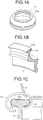
- FIG. 1A is a perspective view of a ring in an example configuration of a ring/traveler system for a ring spinning machine;
- FIG. 1B is a partially enlarged perspective view of the ring in this example configuration of a ring/traveler system for a ring spinning machine;
- FIG. 1C is a schematic perspective view showing a relationship between the traveler and the ring during spinning in this example configuration of a ring/traveler system for a ring spinning machine;
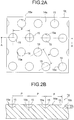
- FIG. 2A is a front view showing a periodic structure portion realized by dimples;
- FIG. 2B is an A-A sectional view of FIG. 2A;
- FIG. 3 is a schematic view illustrating shape parameters of the dimple;
- FIG. 4 is a schematic view showing a first modified example of a sectional shape of the dimple;
- FIG. 5 is a schematic view showing a second modified example of the sectional shape of the dimple;
- FIG. 6 is a schematic view showing interrelationships between a dimple wall surface angle and a value of P/D and functions for storing and resupplying an accretion;
- FIG. 7 is a view showing evaluation results obtained in examples and comparative examples relating to the useful life of the ring/traveler system;
- FIG. 8A is a front view of dimples formed under conditions of example 1;
- FIG. 8B is a sectional view of the dimples formed under the conditions of example 1;
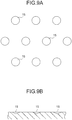
- FIG. 9A is a front view of dimples formed under conditions of example 2;
- FIG. 9B is a sectional view of the dimples formed under the conditions of example 2;
- FIG. 10A is a front view of dimples formed under conditions of example 3;
- FIG. 10B is a sectional view of the dimples formed under the conditions of example 3;
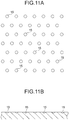
- FIG. 11A is a front view of dimples formed under conditions of example 4;
- FIG. 11B is a sectional view of the dimples formed under the conditions of example 4;
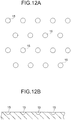
- FIG. 12A is a front view of dimples formed under conditions of example 5;
- FIG. 12B is a sectional view of the dimples formed under the conditions of example 5;
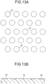
- FIG. 13A is a front view of dimples formed under conditions of comparative example 1;
- FIG. 13B is a sectional view of the dimples formed under the conditions of comparative example 1;
- FIG. 14A is a front view of dimples formed under conditions of comparative example 2;
- FIG. 14B is a sectional view of the dimples formed under the conditions of comparative example 2;
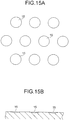
- FIG. 15A is a front view of dimples formed under conditions of comparative example 3;
- FIG. 15B is a sectional view of the dimples formed under the conditions of comparative example 3;
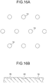
- FIG. 16A is a front view of dimples formed under conditions of comparative example 4; and
- FIG. 16B is a sectional view of the dimples formed under the conditions of comparative example 4.
DESCRIPTION OF THE PREFERRED EMBODIMENTS
-
An embodiment of the present invention will be described in detail below with reference to the figures.
-
FIG. 1A is a perspective view of a ring in an example configuration of a ring/traveler system for a ring spinning machine. FIG. 1B is a partially enlarged perspective view of the ring in this example configuration of a ring/traveler system for a ring spinning machine. FIG. 1C is a schematic perspective view showing a relationship between the traveler and the ring during spinning in this example configuration of a ring/traveler system for a ring spinning machine. The term "ring spinning machine" denotes a spinning machine such as a ring spinning machine or a ring twisting machine in which yarn is wound via a traveler that travels (slides) around a ring that ascends and descends while supported by a ring rail.
-
In FIGS. 1A to 1C, a ring 11 and a traveler 12 together constitute the ring/traveler system. The ring 11 is formed from bearing steel, for example. A flange 11a is formed on the ring 11 so as to be structured integrally with the ring 11. The flange 11a is formed to have a T-shaped cross-section.
-
The traveler 12, meanwhile, is formed from oxidation-treated spring steel, for example. The traveler 12 is formed in a C shape. The traveler 12 is mounted on the flange 11a of the ring 11.
-
A chromium plating layer 13 is formed on the surface of the flange 11a of the ring 11. The chromium plating layer 13 is preferably formed from a hard chromium plating layer with a thickness of approximately 10 to 20 µm, for example. A hard chromium plating layer is a plating layer defined in JIS H8615 Chromium plating for engineering purposes. A periodic structure portion 14 is formed on the chromium plating layer 13 covering the flange 11a in at least a surface layer part of the chromium plating layer 13 covering an inner peripheral surface of the flange 11a. The periodic structure portion 14 is a part for reducing component wear that occurs when the traveler 12 slides around the ring 11.
-
Note that in this embodiment, the flange 11a of the ring 11 is covered by the chromium plating layer 13, and the periodic structure portion 14 is formed on the inner peripheral surface of the flange 11a via the chromium plating layer 13. The film covering the flange 11a is not limited to the chromium plating layer 13, however, and any surface-treated film having either approximately identical mechanical characteristics to the chromium plating layer 13 or higher mechanical characteristics than the traveler material, such as nickel plating having a higher hardness than the traveler material, for example, may be used instead.
-
As shown in FIG. 1C, when yarn is wound onto a bobbin in the ring spinning machine, yarn Y is passed through the traveler 12. The yarn Y is fed from a drafting device, not shown in the figures, and wound onto a bobbin (not shown) via the traveler 12. At this time, a predetermined tension is applied to the yarn Y passing through the traveler 12. Accordingly, the traveler 12 is pulled by the yarn Y so as to contact the flange 11a of the ring 11, and while maintaining this state of contact, moves so as to revolve around the flange 11a. Therefore, while the yarn Y is being wound onto the bobbin, or in other words during spinning, the traveler 12 slides (travels) around the ring 11.
-
Here, a sliding surface on which the traveler 12 and the ring 11 slide as the traveler 12 travels is a surface on which the ring 11 and the traveler 12 contact each other. Therefore, a sliding surface between the traveler 12 and the ring 11 exists on both the ring 11 and the traveler 12. In this embodiment, as an example, the periodic structure portion 14 is formed on the sliding surface on which the ring 11 slides relative to the traveler 12. More specifically, a configuration in which the inner peripheral surface of the flange 11a of the ring 11 is covered by the chromium plating layer 13 and the periodic structure portion 14 is formed on the surface of the chromium plating layer 13 is employed. In this embodiment, therefore, the periodic structure portion 14 on the chromium plating layer 13 covering the inner peripheral surface of the flange 11a corresponds to the sliding surface between the traveler 12 and the ring 11.
-
As shown in FIGS. 2A and 2B, a plurality of dimples 15 are formed in the periodic structure portion 14 of the chromium plating layer 13. FIG. 2A is a front view of the periodic structure portion, and FIG. 2B is an A-A sectional view of FIG. 2A.
-
The periodic structure portion 14 is formed by arranging the plurality of dimples 15 periodically at a predetermined pitch. In this embodiment, as an example, the plurality of dimples 15 are arranged in a staggered pattern. Each dimple 15 is formed as a recess in a main surface 14a of the periodic structure portion 14. The main surface 14a of the periodic structure portion 14 is a surface excluding the recessed parts formed by the dimples 15. The plurality of dimples 15 each have a circular open end 15a. The open end 15a of each dimple 15 opens in a circular shape onto the main surface 14a of the periodic structure portion 14. Each dimple 15 is formed to have a rounded cone-shaped cross-section. Further, each dimple 15 has a wall surface 15b that rises diagonally from a bottom portion of the dimple 15 toward the main surface 14a of the periodic structure portion 14.
-
In this embodiment, the plurality of dimples 15 forming the periodic structure portion 14 are formed to satisfy the following two conditions simultaneously.
-
(Condition 1) The dimple wall surface angle is not less than 10° and not more than 65°
-
(Condition 2) The value of P/D, where P is the pitch (µm) at which the plurality of dimples 15 are arranged over the periodic structure portion 14 and D is the diameter (µm) of the circular open end 15a, is not less than 1.9 and not more than 4.5.
-
Respective definitions of the dimple wall surface angle, the arrangement pitch of the plurality of dimples 15 (also referred to as the "dimple pitch" hereafter), the diameter of the circular open end 15a (also referred to as the "dimple diameter" hereafter), and the depth of the dimple 15 (also referred to as the "dimple depth" hereafter) will now be described.
-
As shown in FIG. 3, the dimple wall surface angle is denoted by an angle θ (°) formed by the main surface 14a and the wall surface 15b at the open end 15a where the wall surface 15b of the dimple 15 contacts the main surface 14a of the periodic structure portion 14. As illustrated in FIGS. 2A and 2B, the dimple pitch is denoted by a center-to-center distance P (µm) between two adjacent dimples 15 on the main surface 14a of the periodic structure portion 14. Note that FIGS. 2A and 2B show an example in which the arrangement pitch P of the dimples 15 is identical in all directions, but the arrangement pitch may be varied according to the direction of the adjacent dimples 15. It should be noted, however, that when two or more different arrangement pitches exist, the value of P/D must satisfy (Condition 2) described above in relation to all of the arrangement pitches. As shown in FIG. 3, the dimple diameter is denoted by a diameter D (µm) of the open end 15a of the dimple 15, which opens in a circular shape onto the main surface 14a of the periodic structure portion 14. As shown in FIG. 3, the dimple depth is denoted by a maximum depth S (µm) of the dimple 15, using the main surface 14a of the periodic structure portion 14 as a reference.
-
Note that FIG. 3 shows an example in which the dimples 15 have a rounded cone-shaped cross-section, but the present invention is not limited thereto, and instead, for example, the employed dimples 15 may have a pointed cone-shaped cross-section, as shown in FIG. 4, or a trapezoidal cross-section, as shown in FIG. 5. Regardless of the employed sectional shape, the open end 15a of the dimple 15 is circular.
-
The term "circular" used to describe the opening shape of the open end 15a preferably denotes a perfect circle. The present invention is not limited thereto, however, and the term "circular" may denote an ellipse having an ellipticity of at least 0.8, for example. As regards the dimple wall surface angle θ in this case, the dimple wall surface angle θ should satisfy the condition of being not less than 10° and not more than 65° in at least one of a long axis direction and a short axis direction of the ellipse. Further, as regards the dimple diameter, the condition according to which the value of P/D is not less than 1.9 and not more than 4.5 should be satisfied when the length of at least one of a long axis and a short axis of the ellipse is applied as the dimple diameter D (µm).
-
The dimple depth S of each of the plurality of dimples 15 is preferably not less than 2 µm. Further, the dimple diameter D is preferably not less than 10 µm and not more than 60 µm. Furthermore, a dimple area ratio of the periodic structure portion 14 is preferably not less than 4% and not more than 20%. The dimple area ratio is a value expressing the ratio of the entire surface area of the dimples 15 to the entire surface area of the sliding surface between the traveler 12 and the ring 11 as a percentage.
-
The plurality of dimples 15 can be formed by laser processing, for example. When the dimples 15 are formed by laser processing, picosecond laser processing using picosecond pulsed laser light is preferably applied. In picosecond laser processing, the position in which the workpiece is irradiated with the laser light can be varied by controlling the orientation of the picosecond pulsed laser light emitted by a laser oscillator using a galvanometer optical system. Hence, when the periodic structure portion 14 is to be provided on the ring 11, the plurality of dimples 15 can be formed in a desired arrangement by irradiating the sliding surface of the ring 11 with picosecond pulsed laser light using a galvanometer optical system and successively shifting the irradiation position using the galvanometer optical system.
-
A mechanism by which the periodic structure portion 14 reduces wear will now be described.
-
First, in this embodiment, the sliding surface between the ring 11 and the traveler 12 is a surface on which sliding is performed in an environment without liquid lubrication. "Without liquid lubrication" indicates a state in which no liquid lubricant exists. Typically, when metals slide against each other in an environment without liquid lubrication, severe wear occurs on the sliding surface. In a ring/traveler system, the traveler 12 revolves around the ring 11 at a particularly high speed, and therefore wear may be expected to advance rapidly on the sliding surfaces of the two components, leading to seizure occurring within a period of several minutes to several hours. In an actual ring/traveler system, however, contrary to expectation, wear advances slowly. During cotton spinning, for example, the traveler 12 can often be used for up to one or two weeks without being replaced. In tribological terms, therefore, the sliding surface between the ring 11 and the traveler 12 is believed to be in a boundary lubrication state rather than a non-lubricated state. More specifically, it is assumed that due to a lubricating function realized when an accretion containing a yarn-derived lubricating component (mainly carbon) adheres to the travel surface by which the traveler 12 travels around the ring 11 and spreads thinly and evenly over the travel surface, solid contact between the metals constituting the ring 11 and the traveler 12 is suppressed, with the result that wear on the sliding surface is reduced. Further, it is assumed that the accretion is generated when cellulose fibers separate from the yarn Y that passes through the traveler 12 during spinning and these fibers becomes intertwined with wear debris from the traveler and so on. In Reference Document 1, described below, it is reported that the frictional force generated between the ring 11 and the traveler 12 during spinning using a single spinning machine was half the frictional force of a test machine in which spinning was not performed. In Reference Document 2, described below, it is reported that due to the lubricating function realized during spinning, the wear speed of the traveler 12 was lower than the wear speed of a test machine in which spinning was not performed. It is therefore evident that due to the lubricating function typically realized during spinning, frictional force can be reduced in comparison with a test machine in which spinning is not performed, with the result that wear can be suppressed, but wear cannot be prevented completely, meaning that solid contact cannot be prevented sufficiently. According to the present invention, the typical lubricating function of a ring/traveler system can be greatly improved by employing dimples.
-
(Reference Document 1) Yorikazu Shimotsuma and Takuzo Fujii, Journal of Textile Engineering, Wear Characteristics and Speed Limits of a High-speed Ring/Traveler Mechanism, 1969, Vol. 22, No. 11, P775-P784
-
(Reference Document 2) Yorikazu Shimotsuma and Takuzo Fujii, Journal of Textile Engineering, Wear Characteristics of a Ring/Traveler Mechanism, 1970, Vol. 23, No. 4, P267-P277
-
In the ring/traveler system according to this embodiment, the plurality of dimples 15 are formed on the sliding surface on which the ring 11 and the traveler 12 slide as the traveler 12 travels. The yarn Y wound onto the bobbin via the traveler 12 generates wear debris in the form of cellulose fibers by sliding along the traveler 12, which possesses surface roughness. At this time, fluff previously integrated with the yarn Y is sheared so as to separate from the yarn Y. Cellulose fibers in the wear debris, the fluff, and so on are generated in the sliding sites between the ring 11 and the traveler 12 and also fly out to the periphery thereof. Hence, when the cellulose fibers that separate from the yarn Y enter the sliding surface between the ring 11 and the traveler 12, some of the fibers flow into the dimples 15 formed in the sliding surface, while the majority of the fibers move within the sliding surface such that a yarn-derived lubricating component contained in the fibers spreads over the sliding surface between the ring 11 and the traveler 12 and the inner surfaces of the dimples 15 in the form of a thin film. In other words, the cellulose fibers containing the yarn-derived lubricating component are believed to adhere in part to the dimples 15 so as to be held therein, and to flow while spreading over the sliding surface between the ring 11 and the traveler 12 in the form of a thin film. As a result, a film of accretion containing cellulose fibers is formed on the sliding surface between the ring 11 and the traveler 12, and due to the lubricating function of the film, as well as a function thereof for preventing direct contact between the ring 11 and the traveler 12, a wear-reducing effect is obtained. Hence, wear on the ring 11 and the traveler 12 can be suppressed even in an environment without liquid lubrication. In a typical ring 11 not having the dimples 15, spaces for holding adhered cellulose fibers are limited to extremely small spaces that are formed between the ring 11 and the traveler 12 by the roughness on the respective surfaces thereof. When a ring 11 not having the dimples 15 is used, therefore, the volume of the spaces for holding adhered cellulose fibers is greatly reduced in comparison with a case where the ring 11 having the dimples 15 is used. As a result, when a ring 11 not having the dimples 15 is used, the surface area of the film believed to be formed by expansion of the accretion is extremely small in comparison with a case where the ring 11 having the dimples 15 is used, and this can be interpreted as the reason why the surface area of solid contact between the ring 11 and the traveler 12 increases.
-
To ensure that the lubricating function realized by the accretion remains in a favorable state, the dimples 15 must fulfill a function for storing the accretion containing the yarn-derived lubricating component and a function for resupplying the stored accretion to the sliding surface. In other words, the dimples 15 serve to maintain the lubricating function realized by the accretion by taking in and storing the accretion generated during spinning and resupplying the stored accretion to the sliding surface. Following in-depth study, the inventors found that the dimple wall surface angle θ and the value of P/D, as described above, are both closely related to the accretion storing function and the accretion resupplying function, as shown in FIG. 6.
-
When considering the accretion storing function and the accretion resupplying function, it is necessary to ascertain the flow behavior of the accretion in the spaces between the traveler 12 and the ring 11. Centrifugal force from the traveler 12 acts on the accretion as force (referred to hereafter as "vertical force") acting on the ring 11 in a vertical direction, while rotary force generated in the traveler 12 when the yarn Y is wound onto the bobbin acts on the accretion as shearing force. Hence, compressive force and shearing force act on the accretion simultaneously. Since wear is observed on the traveler 12, it is clear that sufficient strength for preventing solid contact between the ring 11 and the traveler 12 is not generated when the aforesaid vertical force and shearing force act on the accretion. Accordingly, the accretion is believed to flow as the traveler 12 moves, thereby becoming sandwiched between the traveler 12 and the ring 11 so as to suppress solid contact. When the dimple wall surface angle θ is small, resistance to the flow of the accretion is low, and therefore the accretion moves more easily. When the dimple wall surface angle θ is large, on the other hand, resistance to the flow of the accretion is high, and therefore the accretion moves less easily. When the resistance is extremely high, it is thought that the accretion flows over the surface of the ring 11 while the cellulose that has accumulated in the dimples remains therein. The value of P/D, meanwhile, denotes a ratio of the length of the surface on which solid contact occurs to the length of the accretion stored in the dimples 15. It is assumed, from the resulting increase in the useful life of the traveler 12, that there is a period in which the accretion sandwiched between the ring 11 and the traveler 12 suppresses solid contact by forming a space while moving within a range of the length of the surface on which solid contact occurs. It is believed that although vertical force acts on the ring 11 from the traveler 12, an opposing force equaling or exceeding the vertical force is generated by the flow of the accretion. When the value of P/D is small, the accretion flows within the dimples such that the generated opposing force is insufficient, leading to a relative increase in surface pressure outside the dimples, and as a result, the accretion is removed, making solid contact between the ring 11 and the traveler 12 more likely to occur. When the value of P/D is large, the length on which the opposing force is generated increases, but since the amount of cellulose stored in the dimples is small, the space between the ring 11 and the traveler 12 in which the accretion spreads evenly is small, and as a result, solid contact is more likely to occur. The dimple wall surface angle θ and the value of P/D, i.e. the two elements required to store and resupply the accretion, are both linked to the flow of the accretion and must therefore be satisfied simultaneously. In a ring spinning machine, as is evident from the high-speed photographs of the traveler behavior shown in Reference Document 3, described below, and the contact sites of the traveler in Reference Document 1, described above, the contact sites of the traveler are not fixed. Hence, the dimple wall surface angle θ and the value of P/D cannot be determined by calculation, and therefore numerical values thereof are determined by experiment. More specifically, when the dimple wall surface angle θ is too large or too small, the accretion cannot be stored easily in the dimples and cannot be resupplied easily to the sliding surface. Likewise when the value of P/D is too large or too small, the accretion cannot be stored easily in the dimples and cannot be resupplied easily to the sliding surface. Therefore, the dimple wall surface angle θ is preferably not less than 10° and not more than 65°, and the value of P/D is preferably not less than 1.9 and not more than 4.5. By prescribing the dimple wall surface angle θ and the value of P/D thus, the accretion can be stored easily in the dimples 15, and the stored accretion can be resupplied easily to the sliding surface. Hence, the lubricating function realized by the accretion can be maintained in a favorable state, and as a result, the useful life of the ring/traveler system can be further extended.
-
(Reference Document 3) Yorikazu Shimotsuma and Takuzo Fujii, Journal of Textile Engineering, Traveler Behavior in a High-speed Ring/Traveler Mechanism, 1969, Vol. 22, No. 7, P493-P499
Examples
-
To confirm the wear-reducing effect of the periodic structure portion 14, the inventors evaluated the useful life of the components using rings 11 having dimples 15 formed under different conditions. Results are shown in FIG. 7.
-
In FIG. 7, the evaluation subject component is divided into example 1, example 2, example 3, example 4, example 5, comparative example 1, comparative example 2, comparative example 3, and comparative example 4. In examples 1 to 4 and comparative examples 1 to 3 of these examples, the dimple sectional shape is a rounded cone shape. In example 5, the dimple sectional shape is trapezoidal, and in comparative example 4, the dimple sectional shape is rectangular. The formation conditions of the dimples 15 will be described in detail below.
Example 1
-
In example 1, the dimples 15 were formed under the following conditions: dimple wall surface angle = 11.3°; P/D = 3.5; dimple area ratio = 6%; dimple diameter = 20 µm; dimple depth = 2 µm; dimple pitch = 70 µm. FIG. 8A is a front view of the dimples formed under the conditions of example 1, and FIG. 8B is a sectional view of the dimples.
Example 2
-
In example 2, the dimples 15 were formed under the following conditions: dimple wall surface angle = 21.8°; P/D = 2.5; dimple area ratio = 13%; dimple diameter = 40 µm; dimple depth = 8 µm; dimple pitch = 100 µm. FIG. 9A is a front view of the dimples formed under the conditions of example 2, and FIG. 9B is a sectional view of the dimples.
Example 3
-
In example 3, the dimples 15 were formed under the following conditions: dimple wall surface angle = 28.1°; P/D = 2.5; dimple area ratio = 13%; dimple diameter = 30 µm; dimple depth = 8 µm; dimple pitch = 75 µm. FIG. 10A is a front view of the dimples formed under the conditions of example 3, and FIG. 10B is a sectional view of the dimples.
Example 4
-
In example 4, the dimples 15 were formed under the following conditions: dimple wall surface angle = 39°; P/D = 3; dimple area ratio = 9%; dimple diameter = 10 µm; dimple depth = 4 µm; dimple pitch = 30 µm. FIG. 11A is a front view of the dimples formed under the conditions of example 4, and FIG. 11B is a sectional view of the dimples.
Example 5
-
In example 5, the dimples 15 were formed under the following conditions: dimple wall surface angle = 60°; P/D = 3.04; dimple area ratio = 8%; dimple diameter = 23 µm; dimple depth = 10 µm; dimple pitch = 70 µm. FIG. 12A is a front view of the dimples formed under the conditions of example 5, and FIG. 12B is a sectional view of the dimples.
Comparative Example 1
-
In comparative example 1, the dimples 15 were formed under the following conditions: dimple wall surface angle = 17.7°; P/D = 1.6; dimple area ratio = 31%; dimple diameter = 25 µm; dimple depth = 4 µm; dimple pitch = 40 µm. FIG. 13A is a front view of the dimples formed under the conditions of comparative example 1, and FIG. 13B is a sectional view of the dimples.
Comparative Example 2
-
In comparative example 2, the dimples 15 were formed under the following conditions: dimple wall surface angle = 8.1°; P/D = 5; dimple area ratio = 3%; dimple diameter = 14 µm; dimple depth = 2 µm; dimple pitch = 70 µm. FIG. 14A is a front view of the dimples formed under the conditions of comparative example 2, and FIG. 14B is a sectional view of the dimples.
Comparative Example 3
-
In comparative example 3, the dimples 15 were formed under the following conditions: dimple wall surface angle = 11°; P/D = 1.75; dimple area ratio = 26%; dimple diameter = 40 µm; dimple depth = 4 µm; dimple pitch = 70 µm. FIG. 15A is a front view of the dimples formed under the conditions of comparative example 3, and FIG. 15B is a sectional view of the dimples.
Comparative Example 4
-
In comparative example 4, the dimples 15 were formed under the following conditions: dimple wall surface angle = 90°; P/D = 3.5; dimple area ratio = 6%; dimple diameter = 20 µm; dimple depth = 4 µm; dimple pitch = 70 µm. FIG. 16A is a front view of the dimples formed under the conditions of comparative example 4, and FIG. 16B is a sectional view of the dimples.
-
Note that FIGS. 9A to 16B do not necessarily show the dimensions of the dimples at the correct scale.
-
To evaluate the useful life, an unused traveler 12 was attached to each of the rings 11 in which the dimples 15 were formed under different conditions, as described above, and the useful life of the traveler 12 was checked in an actual machine test. The actual machine test was implemented in a dry condition environment using a ring spinning machine (RX240) manufactured by Toyota Industries Corporation, with the rotation speed of a spindle set at 21000 rpm. The spindle rotates integrally with the bobbin while supporting the bobbin. The useful life of the traveler 12 was determined on the basis of the wear level of the traveler 12. More specifically, the traveler 12 was determined to have reached the end of its useful life when the thickness of the traveler 12 decreased to half the initial thickness of the traveler 12 at the start of the test.
-
Further, to evaluate the useful life, the distance traveled by the traveler at the end of the useful life of the traveler 12 in an actual machine test implemented using a ring 11 not formed with the dimples 15 was set as a reference distance L (km). An actual machine test was then implemented for each of examples 1 to 5 and comparative examples 1 to 4, and a result obtained by dividing the distance traveled by the traveler in each example and each comparative example by the aforesaid reference distance L was set as a useful life ratio.
-
As is evident from FIG. 7, examples 1 to 5 satisfy both condition 1, according to which the dimple wall surface angle θ is not less than 10° and not more than 65°, and condition 2, according to which the value of P/D is not less than 1.9 and not more than 4.5. Comparative example 1 and comparative example 3, meanwhile, satisfy condition 1 but do not satisfy condition 2. Comparative example 2 satisfies neither condition 1 nor condition 2. Comparative example 4 satisfies condition 2 but does not satisfy condition 1.
-
As regards the useful life, meanwhile, the useful life ratio is 1 in all of comparative examples 1 to 4. Therefore, even when the dimples 15 are formed under the conditions of comparative examples 1 to 4, the useful life of the ring/traveler system cannot be extended. In particular, it was learned that when the value of P/D is smaller than 1.8, as in comparative examples 1 and 3, the useful life of the traveler 12 does not increase even though the dimple wall surface angle θ satisfies condition 1. It was also learned that the useful life of the traveler 12 does not increase when the value of P/D is larger than 4.5, as in comparative example 2. Hence, to extend the useful life of the traveler 12, the value of P/D must be held within a range of not less than 1.9 and not more than 4.5.
-
In all of examples 1 to 5, on the other hand, the useful life ratio equals or exceeds 2. Hence, by forming the dimples 15 under the conditions of examples 1 to 5, the useful life of the ring/traveler system can be extended by a multiple of two or more in comparison with comparative examples 1 to 4. In particular, when the dimples 15 are formed under conditions of dimple wall surface angle = 21.8° and P/D = 2.5, as in example 2, the useful life of the traveler 12 increases by a multiple of 3.3. Note that when the dimples 15 were formed under the conditions of examples 1 to 5, the accretion generated during spinning spreads thinly over the sliding surface by a coverage of at least 50%, or even at least 80%, and this is assumed to lead to a further increase in the useful life of the ring/traveler system.
-
Further, the accretion generated during spinning is stored temporarily in the dimples 15, but when the dimples 15 are too shallow at this time, the accretion may be stored in the dimples 15 in an insufficient amount. Therefore, the dimple depth S is preferably at least 2 µm, more preferably at least 4 µm, and even more preferably at least 6 µm. Note, however, that when the dimples 15 are too deep, it may be difficult to resupply the accretion to the sliding surface. Therefore, the dimple depth S preferably satisfies a condition of being not more than 20 µm.
-
Meanwhile, in examples 1 to 5, the relationship between the dimple diameter and the useful life ratio is such that when the dimple diameter D is not less than 10 µm and not more than 60 µm, the useful life ratio equals or exceeds 2. In examples 2 and 3 in particular, in which the dimple diameter D satisfies a condition of being not less than 30 µm and not more than 60 µm, the useful life ratio equals or exceeds a multiple of 2.3. Hence, the dimple diameter D is preferably not less than 10 µm and not more than 60 µm, and more preferably not less than 30 µm and not more than 60 µm.
-
Furthermore, when the dimple area ratio is compared between comparative examples 1 to 4 and examples 1 to 5, the dimple area ratio exceeds 20% in comparative examples 1 and 3 and is 3% in comparative example 2, whereas in examples 1 to 5, the dimple area ratio satisfies a condition of being not less than 4% and not more than 20%. In examples 1 to 5, the useful life ratio is at least 2 times greater than in comparative examples 1 to 4, and in examples 2 and 3 in particular, the useful life ratio equals or exceeds a multiple of 2.3. Hence, the dimple area ratio is preferably not less than 4% and not more than 20%, and more preferably not less than 10% and not more than 15%.
Effects of Embodiment
-
In this embodiment of the present invention, the plurality of dimples 15 formed in the sliding surface between the ring 11 and the traveler 12 satisfy a condition according to which the dimple wall surface angle θ is not less than 10° and not more than 65° and a condition according to which the value of P/D is not less than 1.9 and not more than 4.5. As a result, the accretion generated during spinning can be stored easily in the dimples 15, and the stored accretion can be resupplied easily to the sliding surface. Hence, the lubricating function realized by the accretion can be maintained in a favorable state, enabling a large reduction in wear on the components of the ring/traveler system. According to this embodiment, therefore, the shape and arrangement of the dimples formed in the sliding surface between the traveler and the ring can be optimized, enabling a further increase in the useful life of the ring/traveler system.
Modified Examples etc.
-
The technical scope of the present invention is not limited to the embodiment described above and also includes embodiments realized by applying various modifications and amendments within a scope from which the specific effects obtained by the constituent elements of the invention and combinations thereof can be derived.
-
For example, in the above embodiment, an example in which the plurality of dimples 15 are arranged in a staggered pattern was described, but the present invention is not limited thereto, and the plurality of dimples 15 may be arranged in a lattice shape, for example.
-
Further, the spun yarn is not limited to cotton, and hemp, silk, wool, or chemical fiber (rayon, nylon, vinylon, or fleece), for example, may be used instead. Among these materials, cotton and hemp are preferable in consideration of the ease with which the accretion spreads over the sliding surface.
-
Moreover, the ring 11 forming the ring/traveler system is not limited to a ring including the flange 11a having a T-shaped cross-section and may be a ring including a tapered flange, for example. In this case, a traveler having a suitable shape for the tapered flange is used.
-
Furthermore, in the above embodiment, an example in which the plurality of dimples 15 are formed by laser processing was described, but the present invention is not limited thereto, and another processing method, such as pressing, drilling, or etching, for example, may be applied.
-
In a ring/traveler system for a ring spinning machine in which sliding is performed in an environment without liquid lubrication, a plurality of dimples, each having a circular open end, are formed in a sliding surface on which a traveler and a ring slide as the traveler travels, and the plurality of dimples satisfy a condition according to which a dimple wall surface angle is not less than 10° and not more than 65° and satisfy a condition according to which a value of P/D, where P is a pitch (µm) at which the plurality of dimples are arranged over the sliding surface and D is a diameter (µm) of the circular open end, is not less than 1.9 and not more than 4.5.