EP2933205A1 - Schutzvorrichtung für coils - Google Patents
Schutzvorrichtung für coils Download PDFInfo
- Publication number
- EP2933205A1 EP2933205A1 EP15163975.4A EP15163975A EP2933205A1 EP 2933205 A1 EP2933205 A1 EP 2933205A1 EP 15163975 A EP15163975 A EP 15163975A EP 2933205 A1 EP2933205 A1 EP 2933205A1
- Authority
- EP
- European Patent Office
- Prior art keywords
- magnet
- core
- coils
- coil
- protective device
- Prior art date
- Legal status (The legal status is an assumption and is not a legal conclusion. Google has not performed a legal analysis and makes no representation as to the accuracy of the status listed.)
- Granted
Links
Images


Classifications
-
- B—PERFORMING OPERATIONS; TRANSPORTING
- B65—CONVEYING; PACKING; STORING; HANDLING THIN OR FILAMENTARY MATERIAL
- B65D—CONTAINERS FOR STORAGE OR TRANSPORT OF ARTICLES OR MATERIALS, e.g. BAGS, BARRELS, BOTTLES, BOXES, CANS, CARTONS, CRATES, DRUMS, JARS, TANKS, HOPPERS, FORWARDING CONTAINERS; ACCESSORIES, CLOSURES, OR FITTINGS THEREFOR; PACKAGING ELEMENTS; PACKAGES
- B65D85/00—Containers, packaging elements or packages, specially adapted for particular articles or materials
- B65D85/66—Containers, packaging elements or packages, specially adapted for particular articles or materials for jumbo rolls; for rolls of floor covering
-
- B—PERFORMING OPERATIONS; TRANSPORTING
- B65—CONVEYING; PACKING; STORING; HANDLING THIN OR FILAMENTARY MATERIAL
- B65D—CONTAINERS FOR STORAGE OR TRANSPORT OF ARTICLES OR MATERIALS, e.g. BAGS, BARRELS, BOTTLES, BOXES, CANS, CARTONS, CRATES, DRUMS, JARS, TANKS, HOPPERS, FORWARDING CONTAINERS; ACCESSORIES, CLOSURES, OR FITTINGS THEREFOR; PACKAGING ELEMENTS; PACKAGES
- B65D21/00—Nestable, stackable or joinable containers; Containers of variable capacity
- B65D21/02—Containers specially shaped, or provided with fittings or attachments, to facilitate nesting, stacking, or joining together
- B65D21/0209—Containers specially shaped, or provided with fittings or attachments, to facilitate nesting, stacking, or joining together stackable or joined together one-upon-the-other in the upright or upside-down position
- B65D21/0224—Auxiliary removable stacking elements other than covers
Definitions
- the invention relates to a protective device for coils with a core.
- Such protections are used by steel manufacturers and processing companies where steel coils are stored or stacked on top of each other.
- the protective device has the function of not damaging the surface of the respective coils which are stacked on top of each other.
- anti-slip strips consist of granulated waste rubber, which is bonded via an adhesive.
- the protective effect of these "anti-slip strips” is similar to the "full-rubber strips”. Both materials are not oil resistant. As a result, the strips become brittle after a certain period of use and dissolve. In this aging process remain material residues on the coils, due to the resolution. These material residues are undesirable to end customers.
- a protective device for coils has a core and a magnet. Due to the fact that coils usually have magnetic materials such as steel, the core of a protection device can be held in position relative to the coil by means of a magnet.
- the magnet is arranged in the interior of the core. In this way it is prevented that, for example, when stacking two coils one above the other by the weight of the overhead coil, an impression in the respective coil by the magnet is formed. In this way, so the coils are spared because it is not possible to press the magnet inside the core in a coil and thus to damage a web or a point on the coil.
- the core has a guide in which the magnet is arranged.
- the magnet is movable within the core or within the guide of the core.
- the magnet is movable along the guide.
- the magnet can be moved within the guide or along the guide in the core.
- a hard magnet can be arranged within a relatively soft core, wherein the hard magnet in its external dimensions is favorably below the dimensions of the height of the core. In this way it is possible to compress the rubber by two contacting coils, without the magnet being compressed.
- the magnet is mounted floating within the guide.
- Floating bearing in this context means that the magnet can move within the guide, but the magnet within the guide can not change its spatial orientation by rotation. That is, the magnet is supported within the guide but, for example, is unable to rotate about one of its axes.
- its spatial orientation within the guide is always the same, with a linear movement along the guide is possible.
- the orientation of the north and south pole of the magnet is always the same orientation.
- the core has two opposite contact surfaces for contact with coils.
- the core is preferably formed cuboid.
- other shapes are possible, such as e.g. a polygonal-spatial or elliptical-spatial form. It is advantageous if all forms have a height, or a thickness that can accommodate a magnet within the core.
- the contact surfaces are spaced from each other. This is conveniently achieved by a sufficient thickness or height of the protective device or of the core. Furthermore, it is favorable if the guide extends from one contact surface to the other. In this way, a maximum range of motion of the magnet within the guide is achieved. So it is possible that the magnet can be moved within the guide from one contact surface to the other contact surface.
- the core can also be designed so that the range of motion of the magnet is limited by the core. Also, a combination of core and coating is conceivable.
- At least one contact surface of the core has a coating.
- the coating comprises a nitrile rubber. This is particularly resistant to oil.
- the core has a material with high compressibility.
- the core may have rubber as a material. With help the core material rubber, it is possible not only to achieve a high compressibility of the core or the protective device, but also when stacking several coils on top of each other, to prevent imprints of one coil on the other.
- the rubber of the core is bonded by means of adhesive. Due to the high loads, caused by the weight of the coils, it is favorable that the core or the core material rubber is bonded by means of adhesive. In this way, the binding in the rubber can be increased, whereby the load capacity is also increased. Thus, therefore, a high stability of the core is achieved.
- the magnet has neodymium.
- the use of neodymium gives a magnet special strength.
- the magnetic force of the magnet is adjustable in such a way that the magnetic force, together with the force of gravity, releasably fixes the core on a coil. Due to the mobility of the magnet within the core, the magnet can follow gravity.
- a protective device with an arbitrary side can be placed on a coil, wherein the magnet preferably follows within a guide of gravity and thus the smallest possible distance from the coil on which the magnet rests occupies. For the most part, gravity helps to position the magnet inside the core.
- the magnetic force is essentially responsible for the firm hold of the protective device on the coil. Since the magnet or the protective device can be removed without problems from the surface of a coil, the protective device is releasably attachable to a coil.
- the magnetic force of the magnet is adjustable so that this, in particular together with gravity, the core mounted on a coil only with the force necessary for a secure hold force.
- An adjustment of the magnetic force is advantageously carried out in the manufacture of a magnet.
- the magnet has a height that is less than half the distance between the contact surfaces. In this way, the protection device can be compressed without damage due to imprints of the magnet on stacked coils.
- a protective device comprises a core and a magnet, wherein opposite contact surfaces of the core have a coating, and wherein the magnet is arranged within a guide movable in the core.
- a protective device according to the invention can not only be used between coils, it is also possible to use it as edge protection and / or corner protection, wherein changes in position or changes in position of the protective device can be prevented by the use of a magnet.
- Fig. 1 shows a three-dimensional partial view of a protective device 1 for a coil 20. To facilitate reference to properties such as height H, length L and width B of the protective device 1, the size specifications are in Fig. 1 shown.
- the protective device 1 has a core 2 and two magnets 3.
- the core 2 in the present embodiment is made transparent to show its interior.
- the arrangement of the magnets 3 is basically free selectable.
- the magnets 3 are shown at the edge of the illustrated partial section of the protective device 1 in order to facilitate the following description.
- the protective device 1 on the already mentioned magnets 3 which are arranged in the interior of the protective device 1.
- Each of the magnets 3 is located in its own guide 4, within which each magnet 3 is movable.
- the magnets 3 have the task of preventing slippage of the core 2 on a coil 20.
- Each guide 4 extends substantially along the height H in the interior of the protective device 1 and is arranged between two opposite contact surfaces 5a, 5b.
- the contact surfaces ideally have a coating 6 with nitrile rubber in order to withstand oils and fats, which are found to be due to coils. Nitrile rubber is also resistant to swelling in mineral oils, fats and fuels. Consequently, the contact surfaces for direct contact of a coil with the protective device 1 are formed, wherein the contact surfaces 5a, 5b two coils due to the height H of the protective device 1 from each other or to each other or keep at a distance.
- the magnets 3 are floating within the guides 4. This floating storage provides that a mobility in all directions (length L, width B and height H) is ensured.
- each guide 4 has a similar cuboid shape as the magnet 3 arranged therein. In this way, rotation of the magnet 3 within the guide 4 can be prevented. Nevertheless, it is possible to guide the magnet 3 along the height H of the protective device 1. Maintaining the orientation of the Magnets within the guide 4 ensures a constant alignment of the north and south pole of each magnet.
- each magnet can follow gravity.
- the protective device 1 with any side or contact surface 5a, 5b can be placed on a coil, wherein the magnets preferably follow within a guide 4 of gravity.
- the magnets take the smallest possible distance to the coil, on which rest the magnets. In this case, gravity takes over the positioning of the magnets 3 within the core 2.
- the magnetic force is essentially responsible for the firm grip of the protective device 1 on the coil. Due to the magnetic force, the protector 1 is easily removable from the surface of a coil and repositioned or reposable on the same or another coil.
- the magnetic force of the magnet in order not to complicate the removal or removal of a protective device 1 unnecessarily, adjusted so that the core 2 mounted on a coil with the necessary for a secure grip on a coil force.
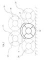
- Fig. 2 shows a schematic bearing arrangement of a plurality of coils 20-24.
- a protection device 1 on the middle lower coil 20 is mounted to represent contact points or contact lines but also contact surfaces of stored or stacked coils.
- the further coils 21 to 24 are shown dotted to highlight the coil 20 with the protection device 1.
- the coils 21 and 22 lie on the coil 20 or on its protective device 1.
- the protective device 1 has a flexible core 2, which comprises, for example, an elastic material such as rubber. Thus, it is the protection device possible to follow the course of the surface of a coil.
- coils are by means of strapping in the circumferential direction (not shown) and by means of strapping 10 secured in the radial direction of steel strips, whereby the coil is held in its wound form. These straps stand out from the surface of each coil.
- the protective device 1 is also used.
- this fulfills a dual function, namely to prevent deformation of coils and strapping. Consequently, by means of the protection device 1, deformation and thus damage of contacting coils or coil strapping can be prevented.
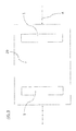
- Figures 3 and 4 show in plan view of a coil 20 different ways of positioning a protective device 1 on a coil.
- the protective devices 1 are oriented transversely to the axis of symmetry A of the coil 20, while in FIG. 4 the protective devices 1 are arranged parallel to the axis of symmetry A of the coil 20.
- the protection device can be aligned to any application and if necessary.
- Fig. 4 illustrates in a cylindrical coil 20 that the protection device 1 fulfills the task to prevent by means of the magnets 3 slippage of the core 2 and the entire protection device on the coil 20.
Landscapes
- Engineering & Computer Science (AREA)
- Mechanical Engineering (AREA)
- Coils Or Transformers For Communication (AREA)
- Electromagnets (AREA)
Abstract
Description
- Die Erfindung betrifft eine Schutzvorrichtung für Coils mit einem Kern.
- Derartige Schutzvorrichtungen werden eingesetzt bei Stahlherstellern sowie weiterverarbeitenden Betrieben, bei denen Stahl-Coils gelagert bzw. übereinander gestapelt werden. Die Schutzvorrichtung hat die Funktion, die Oberfläche der jeweiligen Coils, die aufeinander bzw. übereinander gestapelt werden, nicht zu beschädigen.
- Aus dem Stand der Technik sind Schutzvorrichtungen für Coils bekannt, die einen "Voll-Gummi-Streifen" mit interner Gewebeverstärkung aufweisen. Derartige Voll-Gummi-Streifen sind hochpreisig und erfüllen ihre Funktion nicht im vollen Umfang. Denn aufgrund der Gummioberfläche der Schutzvorrichtung in Zusammenspiel mit einer Öl aufweisenden Oberfläche der Coils, geschieht es häufig, dass bei Belastung bzw. bei Bewegung der Coils die Streifen, die zwischen den Coils angeordnet sind, ihre vorgesehene Position verlassen und zu Boden fallen. Somit kann ein Schutz nicht mehr gewährleistet werden.
- Des Weiteren sind sogenannte "Anti-Rutsch-Streifen" bekannt, welche aus granuliertem Altgummi, der über einen Klebstoff gebunden wird, bestehen. Die Schutzwirkung dieser "Anti-Rutsch-Streifen" ist ähnlich der "Voll-Gummi-Streifen". Beide Materialien sind nicht ölbeständig. Dadurch werden die Streifen nach einer gewissen Einsatzzeit brüchig und lösen sich auf. Bei diesem Alterungsvorgang verbleiben Materialreste auf den Coils, bedingt durch die Auflösung. Diese Materialreste sind von Endkunden unerwünscht.
- Daher ist es Aufgabe der vorliegenden Erfindung, eine Schutzvorrichtung für Coils so auszubilden, dass zum einen eine Lageposition bezüglich eines Coils einfach gehalten werden kann und zum anderen eine einfache Lageänderung der Schutzvorrichtung auf einfache Weise möglich ist.
- Die vorgenannte Aufgabe wird erfindungsgemäß durch die Merkmale des unabhängigen Anspruchs gelöst.
- Weitere vorteilhafte Ausführungsbeispiele der folgenden Erfindung sind Gegenstand der Unteransprüche.
- Erfindungsgemäß ist es vorgesehen, dass eine Schutzvorrichtung für Coils einen Kern und einen Magneten aufweist. Aufgrund der Tatsache, dass Coils in der Regel magnetische Materialien, wie zum Beispiel Stahl, aufweisen, kann mit Hilfe eines Magneten der Kern einer Schutzvorrichtung in seiner Lage bzw. Position bezüglich des Coils gehalten werden.
- Folglich ist es möglich, den Kern einer Schutzvorrichtung mit Hilfe eines Magneten derart an einem Coil zu befestigen, dass der Kern durch äußere Kräfte, wie zum Beispiel die Schwerkraft, oder aber Kräfte hervorgerufen durch andere Coils während des Stapelns bzw. Lagerns, die Position der Schutzvorrichtung nicht oder nicht wesentlich verändert. Denn der Magnet verhindert entsprechend seiner Stärke ein Verrutschen des Kerns.
- Des Weiteren ist es günstig, wenn der Magnet im Inneren des Kerns angeordnet ist. Auf diese Weise wird verhindert, dass zum Beispiel beim Stapeln von zwei Coils übereinander durch die Gewichtskraft des oben liegenden Coils ein Abdruck in dem jeweiligen Coil durch den Magnet entsteht. Auf diese Weise werden also die Coils geschont, da es nicht möglich ist, den Magneten im Inneren des Kerns in einen Coil einzudrücken und somit eine Bahn bzw. eine Stelle an dem Coil zu beschädigen.
- Des Weiteren wird bevorzugt, dass der Kern eine Führung aufweist, in welcher der Magnet angeordnet ist. Auf diese Weise ist der Magnet innerhalb des Kerns bzw. innerhalb der Führung des Kerns bewegbar. Ferner ist es vorteilhaft, wenn der Magnet entlang der Führung bewegbar ist. Somit kann der Magnet innerhalb der Führung bzw. entlang der Führung im Kern bewegt werden. Mit Hilfe dieser Ausgestaltung kann beispielsweise ein harter Magnet innerhalb eines relativ weichen Kerns angeordnet sein, wobei der harte Magnet in seinen äußeren Abmessungen günstigerweise unterhalb der Abmessungen der Höhe des Kerns liegt. Auf diese Weise ist es möglich, den Gummi durch zwei sich berührende Coils zu komprimieren, ohne dass der Magnet komprimiert wird.
- Des Weiteren ist es von Vorteil, wenn der Magnet innerhalb der Führung schwimmend gelagert ist. Eine schwimmende Lagerung in diesem Zusammenhang bedeutet, dass sich der Magnet innerhalb der Führung bewegen kann, jedoch kann der Magnet innerhalb der Führung nicht seine räumliche Orientierung durch Rotation verändern. Das heißt, dass der Magnet innerhalb der Führung gelagert ist aber beispielsweise nicht in der Lage ist, sich um eine seiner Achsen zu drehen. Somit ist seine räumliche Orientierung innerhalb der Führung stets gleich, wobei eine lineare Bewegung entlang der Führung möglich ist. Dadurch ist die Ausrichtung von Nord- und Südpol des Magneten stets gleich orientiert.
- Bevorzugterweise weist der Kern zwei gegenüberliegende Kontaktflächen zur Anlage an Coils auf. Dabei ist der Kern vorzugsweise quaderförmig ausgebildet. Selbstverständlich sind auch andere Formen möglich, wie z.B. eine polygonal-räumliche oder eine elliptisch-räumliche Form. Dabei ist es günstig, wenn alle Formen eine Höhe aufweisen, bzw. eine Dicke, die einen Magneten innerhalb des Kerns aufnehmen kann.
- Des Weiteren ist es bevorzugt, dass die Kontaktflächen zueinander beabstandet sind. Dies wird günstigerweise durch eine ausreichende Dicke bzw. Höhe der Schutzvorrichtung bzw. des Kerns erreicht. Des Weiteren ist es günstig, wenn sich die Führung von einer Kontaktfläche zur anderen erstreckt. Auf diese Weise wird ein maximaler Bewegungsspielraum des Magneten innerhalb der Führung erreicht. So ist es also möglich, dass der Magnet innerhalb der Führung von einer Kontaktfläche zur anderen Kontaktfläche bewegt werden kann. Selbstverständlich kann der Kern auch so ausgebildet sein, dass der Bewegungsspielraum des Magneten durch den Kern begrenzt wird. Auch ist eine Kombination von Kern und Beschichtung denkbar.
- Günstig ist es auch, wenn wenigstens eine Kontaktfläche des Kerns eine Beschichtung aufweist. Mit Hilfe der Beschichtung ist es möglich, den Kern innerhalb der Führung einzuschließen bzw. einen Austritt des Magneten aus der Führung zu verhindern. Aufgrund der Tatsache, dass Coils auf ihrer Oberfläche herstellungsbedingt Öl aufweisen, ist es günstig, wenn die Beschichtung einen Nitrilkautschuk umfasst. Dieser ist besonders widerstandsfähig gegen Öl.
- Des Weiteren ist es günstig, dass der Kern ein Material mit hoher Kompressibilität aufweist. Hierfür kann der Kern Gummi als Material aufweisen. Mit Hilfe des Kernmaterials Gummi ist es möglich, nicht nur eine hohe Kompressibilität des Kerns bzw. der Schutzvorrichtung zu erreichen, sondern auch beim Stapeln von mehreren Coils übereinander, Abdrücke des einen Coils auf dem anderen zu unterbinden.
- Des Weiteren ist es bevorzugt, dass der Gummi des Kerns mittels Klebstoff gebunden ist. Aufgrund der hohen Belastungen, hervorgerufen durch das Gewicht der Coils, ist es günstig, dass der Kern bzw. das Kernmaterial Gummi mittels Klebstoff gebunden ist. Auf diese Weise kann die Bindung im Gummi erhöht werden, wodurch die Belastungsfähigkeit ebenfalls erhöht wird. Somit wird also eine hohe Stabilität des Kerns erreicht.
- Ferner ist es günstig, wenn der Magnet Neodym aufweist. Der Einsatz von Neodym verleiht einem Magneten besondere Stärke.
- Ferner ist es vorteilhaft, wenn die Magnetkraft des Magneten derart einstellbar ist, dass die Magnetkraft zusammen mit der Schwerkraft den Kern auf einem Coil lösbar befestigt. Aufgrund der Beweglichkeit des Magneten innerhalb des Kerns kann der Magnet der Schwerkraft folgen. Somit kann eine Schutzvorrichtung mit einer beliebigen Seite auf einen Coil aufgelegt werden, wobei der Magnet vorzugsweise innerhalb einer Führung der Schwerkraft folgt und somit einen möglichst geringen Abstand zum Coil, auf dem der Magnet aufliegt, einnimmt. Dabei hilft die Schwerkraft größtenteils bei der Positionierung des Magneten innerhalb des Kerns. Hingegen ist im Wesentlichen die Magnetkraft für den festen Halt der Schutzvorrichtung am Coil zuständig. Da der Magnet bzw. die Schutzvorrichtung ohne Probleme von der Oberfläche eines Coils abnehmbar ist, ist die Schutzvorrichtung lösbar befestigbar auf einem Coil. Um jedoch das Entfernen bzw. Abnehmen einer Schutzvorrichtung nicht unnötig zu erschweren, ist die Magnetkraft des Magneten derart einstellbar, dass diese, insbesondere zusammen mit der Schwerkraft, den Kern auf einem Coil lediglich mit der für einen sicheren Halt notwendigen Kraft befestigt. Eine Einstellung der Magnetkraft erfolgt vorteilhafterweise bei der Herstellung eines Magneten.
- Des Weiteren ist es von Vorteil, wenn der Magnet eine Höhe aufweist, die geringer als die Hälfte der Strecke zwischen den Kontaktflächen ist. Auf diese Weise kann die Schutzvorrichtung komprimiert werden, ohne dass eine Beschädigung durch Abdrücke des Magneten auf gestapelten Coils auftritt.
- Die vorher beschriebenen Merkmale, die der Ausbildung einer Schutzvorrichtung dienen, sind frei miteinander kombinierbar.
- So ist es z.B. möglich, dass eine Schutzvorrichtung einen Kern und einen Magneten aufweist, wobei gegenüberliegende Kontaktflächen des Kerns eine Beschichtung aufweisen, und wobei der Magnet innerhalb einer Führung im Kern bewegbar angeordnet ist.
- Des Weiteren kann eine erfindungsgemäße Schutzvorrichtung nicht nur zwischen Coils verwendet werden, auch ist ein Einsatz als Kantenschutz und/oder Eckschutz möglich, wobei Lageänderungen bzw. Positionsänderungen der Schutzvorrichtung mittels der Verwendung eines Magneten verhindert werden können.
- Nachstehend wird die Erfindung anhand eines Ausführungsbeispiels in Verbindung mit zugehörigen Zeichnungen näher erläutert. Diese zeigen schematisch:
- Figur 1
- einen dreidimensionale Teilansicht einer Schutzvorrichtung für Coils;
- Figur 2
- eine Lageranordnung von mehreren Coils;
- Figur 3
- eine erste Orientierung einer Schutzvorrichtung auf einem Coil; und
- Figur 4
- eine zweite Orientierung auf einem Coil.
- In nachfolgender Beschreibung werden gleiche Bezugszeichen für gleiche Gegenstände verwendet.
-
Fig. 1 zeigt eine dreidimensionale Teilansicht einer Schutzvorrichtung 1 für einen Coil 20. Zur leichteren Bezugnahme auf Eigenschaften wie Höhe H, Länge L und Breite B der Schutzvorrichtung 1, sind die genannten Größenangaben inFig. 1 dargestellt. - Die Schutzvorrichtung 1 weist einen Kern 2 und zwei Magneten 3 auf. Der Einfachheit halber ist der Kern 2 im vorliegenden Ausführungsbeispiel transparent ausgebildet, um dessen Innere zu zeigen. Die Anordnung der Magnete 3 ist grundsätzlich frei wählbar. In
Fig. 1 werden die Magnete 3 am Rand des dargestellten Teilausschnitts der Schutzvorrichtung 1 dargestellt, um die nachfolgende Beschreibung zu erleichtert. - Neben dem Kern 2 weist die Schutzvorrichtung 1 die bereits erwähnten Magneten 3 auf, welche im Inneren der Schutzvorrichtung 1 angeordnet sind. Jeder der Magnete 3 befindet sich in einer eigenen Führung 4, innerhalb welcher jeder Magnet 3 bewegbar ist. Die Magnete 3 haben die Aufgabe ein Verrutschen des Kerns 2 auf einem Coil 20 zu verhindern.
- Jede Führung 4 erstreckt sich im Wesentlichen entlang der Höhe H im Inneren der Schutzvorrichtung 1 und ist zwischen zwei gegenüberliegende Kontaktflächen 5a, 5b angeordnet. Die Kontaktflächen weisen idealerweise eine Beschichtung 6 mit Nitrilkautschuk auf, um Ölen und Fetten, welche sich herstellungsbedingt auf Coils finden, zu widerstehen. Nitrilkautschuk ist ferner quellbeständig in Mineralölen, Fetten und Kraftstoffen. Folglich sind die Kontaktflächen für den direkten Kontakt eines Coils mit der Schutzvorrichtung 1 ausgebildet, wobei die Kontaktflächen 5a, 5b zwei Coils aufgrund der Höhe H der Schutzeinrichtung 1 voneinander bzw. zueinander beabstanden bzw. auf Distanz halten.
- Bei Vergleich der Ausmaße bzw. Größenordnung einer Führung 4 mit einem Magneten 3 fällt auf, dass die Magnete 3 eine kleinere Grundfläche aufweisen als die Führung 4. Folglich wird eine Spielpassung zwischen Führung 4 und Magnet 3 erzielt, bei welcher sich der Magnet in Richtung der Breite B sowie der Länge L der Schutzvorrichtung 1 bewegen kann. Zudem ist es natürlich möglich, dass sich die Magnete 2 entlang der Führung bzw. der Höhe H der Schutzvorrichtung 1 bewegen können, da sich ferner die Höhe der Führung 4 von der Höhe des Magneten 3 unterscheidet. Auf diese Weise wird die angesprochene Beweglichkeit jedes Magneten 3 innerhalb der jeweiligen Führung 4 erreicht.
- Anders ausgedrückt sind die Magnete 3 innerhalb der Führungen 4 schwimmend gelagert. Diese schwimmende Lagerung sieht vor, dass eine Beweglichkeit in alle Richtung (Länge L, Breite B und Höhe H) gewährleistet wird.
- Des Weiteren weist jede Führung 4 eine ähnliche quaderförmige Form auf wie der darin angeordnete Magnet 3. Auf diese Weise kann eine Rotation des Magneten 3 innerhalb der Führung 4 verhindert werden. Gleichwohl ist es möglich den Magneten 3 entlang der Höhe H der Schutzvorrichtung 1 zu führen. Die Beibehaltung der Orientierung der Magnete innerhalb der Führung 4 gewährleistet eine stets gleichbleibende Ausrichtung von Nord- und Südpol eines jeden Magnets.
- Aufgrund der Beweglichkeit der Magnete 3 innerhalb des Kerns 2 kann jeder Magnet der Schwerkraft folgen. Somit kann die Schutzvorrichtung 1 mit einer beliebigen Seite bzw. Kontaktfläche 5a, 5b auf einen Coil aufgelegt werden, wobei die Magnete vorzugsweise innerhalb einer Führung 4 der Schwerkraft folgen.
- Somit nehmen die Magnete einen möglichst geringen Abstand zum Coil ein, auf welchem die Magnete aufliegen. Hierbei übernimmt die Schwerkraft die Positionierung der Magnete 3 innerhalb des Kerns 2. Hingegen ist im Wesentlichen die Magnetkraft für den festen Halt der Schutzvorrichtung 1 am Coil zuständig. Aufgrund der Magnetkraft ist die Schutzvorrichtung 1 ohne Probleme von der Oberfläche eines Coils abnehmbar und neu bzw. anders positionierbar auf demselben oder einem anderen Coil.
- Dabei ist die Magnetkraft des Magneten, um das Entfernen bzw. Abnehmen einer Schutzvorrichtung 1 nicht unnötig zu erschweren, derart eingestellt, dass der Kern 2 auf einem Coil mit der für einen sicheren Halt auf einem Coil notwendigen Kraft befestigt.
-
Fig. 2 zeigt eine schematische Lageranordnung von mehreren Coils 20 - 24. Hierbei ist der Übersichtlichkeit halber nur eine Schutzvorrichtung 1 auf dem mittleren unteren Coil 20 angebracht, um Berührungspunkte bzw. Berührungslinien aber auch Berührungsflächen von gelagerten bzw. gestapelten Coils darzustellen. Die weiteren Coils 21 bis 24 sind gepunktet dargestellt, um den Coil 20 mit der Schutzvorrichtung 1 hervorzuheben. Selbstverständlich ist es möglich, auf jedes Coil 20 - 24 eine oder mehrere Schutzvorrichtungen 1 anzubringen. - Wie der
Fig. 2 ferner zeigt, liegen die Coils 21 und 22 auf dem Coil 20 auf bzw. auf dessen Schutzvorrichtung 1. Die Schutzvorrichtung 1 weist einen flexiblen Kern 2 auf, der beispielsweise ein elastisches Material wie Gummi umfasst. Damit ist es der Schutzvorrichtung möglich, dem Verlauf der Oberfläche eines Coils zu folgen. - Aufgrund des enormen Gewicht bzw. der enormen Gewichtskraft eines Coils wird die Schutzvorrichtung 1 komprimiert und zwar hinsichtlich ihrer Höhe. In der Regel sind Coils mittels Umreifungen in Umfangsrichtung (nicht dargestellt) und mittels Umreifungen 10 in Radialrichtung aus Stahlbändern gesichert, wodurch der Coil in seiner aufgewickelten Form gehalten wird. Diese Umreifungen stehen von der Oberfläche eines jeden Coils hervor.
- Um nun Verformungen von Coil-Lagen zu vermeiden, hervorgerufen durch die Umreifung eines angrenzenden Coils, kommt ebenfalls die Schutzvorrichtung 1 zum Einsatz. Somit erfüllt diese eine Doppelfunktion, nämlich Verformungen von Coils sowie von Umreifungen zu unterbinden. Folglich kann mithilfe der Schutzvorrichtung 1 eine Verformung und somit eine Beschädigung von sich kontaktierenden Coils oder Coil-Umreifungen verhindert werden.
- Im Hinblick auf
Fig. 2 bedeutet dies also konkret, dass mithilfe der Schutzvorrichtung 1 eine Beschädigung der Coils 20, 21 und 22 verhindert wird, da sowohl die Umreifungen als auch die Coils selbst nicht unmittelbar miteinander in Kontakt gelangen. -
Figuren 3 und4 zeigen in Draufsicht auf einen Coil 20 unterschiedliche Möglichkeiten der Positionierung einer Schutzvorrichtung 1 auf einem Coil. InFig. 3 sind die Schutzvorrichtungen 1 quer zur Symmetrieachse A des Coils 20 orientiert, während inFigur 4 die Schutzvorrichtungen 1 parallel zur Symmetrieachse A des Coils 20 angeordnet sind. Dies zeigt, dass die Schutzvorrichtung auf jeden Anwendungsfall und Bedarfsfalls ausgerichtet werden kann. Selbstverständlich sind weitere bzw. beliebige Ausrichtungen der Schutzvorrichtung der Symmetrieachse A eines Coils möglich. InsbesondereFig. 4 verdeutlicht bei einem zylindrischen Coil 20, dass die Schutzvorrichtung 1 die Aufgabe erfüllt, mittels der Magnete 3 ein Verrutschen des Kerns 2 bzw. der gesamten Schutzvorrichtung auf dem Coil 20 zu verhindern.
Claims (10)
- Schutzvorrichtung (1) für Coils mit:- einem Kern (2), und- einem Magneten (3).
- Schutzvorrichtung nach Anspruch 1, dadurch gekennzeichnet, dass der Magnet (3) im Inneren des Kerns (2) angeordnet ist.
- Schutzvorrichtung nach Anspruch 1 oder 2, dadurch gekennzeichnet, dass der Kern (2) eine Führung (4) aufweist, in welcher der Magnet angeordnet ist.
- Schutzvorrichtung nach Anspruch 3, dadurch gekennzeichnet, dass der Magnet (3) entlang der Führung (4) bewegbar ist.
- Schutzvorrichtung nach einem der Ansprüche 3 oder 4, dadurch gekennzeichnet, dass der Magnet (3) innerhalb der Führung (4) schwimmend gelagert ist.
- Schutzvorrichtung nach einem der Ansprüche 3 bis 5, dadurch gekennzeichnet, dass der Kern (2) zwei gegenüberliegende Kontaktflächen (5a, 5b) zur Anlage an Coils aufweist, wobei die Kontaktflächen (5a, 5b) zueinander beabstandet sind, und wobei sich die Führung (4) von einer Kontaktfläche zur anderen erstreckt.
- Schutzvorrichtung nach Anspruch 6, dadurch gekennzeichnet, dass wenigstens eine Kontaktfläche (5a, 5b) des Kerns (2) eine Beschichtung (6) aufweist, wobei die Beschichtung (6) vorzugsweise Nitrilkautschuk umfasst.
- Schutzvorrichtung nach einem der vorigen Ansprüche, dadurch gekennzeichnet, dass der Kern (2) ein Material mit hoher Kompressibilität aufweist, wobei vorzugsweise der Kern das Material Gummi aufweist, der mittels Klebstoff gebunden ist, und wobei vorzugsweise der Magnet Neodym aufweist.
- Schutzvorrichtung nach einem der vorigen Ansprüche, dadurch gekennzeichnet, dass die Magnetkraft des Magneten (3) derart einstellbar ist, dass die Magnetkraft zusammen mit der Schwerkraft den Kern (2) auf einem Coil lösbar befestigt.
- Schutzvorrichtung nach einem der von gen Ansprüche, dadurch gekennzeichnet, dass der Magnet (3) eine Höhe aufweist, die geringer ist als die Hälfte der Strecke zwischen den Kontaktflächen (5a, 5b).
Applications Claiming Priority (1)
| Application Number | Priority Date | Filing Date | Title |
|---|---|---|---|
| DE102014105578.0A DE102014105578B4 (de) | 2014-04-17 | 2014-04-17 | Schutzvorrichtung für Coils |
Publications (2)
| Publication Number | Publication Date |
|---|---|
| EP2933205A1 true EP2933205A1 (de) | 2015-10-21 |
| EP2933205B1 EP2933205B1 (de) | 2019-07-31 |
Family
ID=53397771
Family Applications (1)
| Application Number | Title | Priority Date | Filing Date |
|---|---|---|---|
| EP15163975.4A Active EP2933205B1 (de) | 2014-04-17 | 2015-04-17 | Schutzvorrichtung für coils |
Country Status (2)
| Country | Link |
|---|---|
| EP (1) | EP2933205B1 (de) |
| DE (1) | DE102014105578B4 (de) |
Citations (3)
| Publication number | Priority date | Publication date | Assignee | Title |
|---|---|---|---|---|
| US3082896A (en) * | 1960-08-01 | 1963-03-26 | Bean Rubber Mfg Co | Shipping pad |
| SE8204228L (sv) * | 1982-07-08 | 1984-01-09 | Trelleborg Ab | Skyddsanordning for platrullar |
| DE202013101697U1 (de) * | 2012-04-19 | 2013-04-26 | Reinhard Krückemeyer GmbH & Co. KG Schleifmittel und Klebebänder | Verpackungsanordnung an einer Bandmetallrolle |
Family Cites Families (2)
| Publication number | Priority date | Publication date | Assignee | Title |
|---|---|---|---|---|
| US2883045A (en) * | 1957-03-08 | 1959-04-21 | Central States Paper & Bag Co | Packaging covers for coiled sheet material |
| US7080734B1 (en) * | 2000-06-29 | 2006-07-25 | Diversi-Plast Products, Inc. | Industrial reel wrap with scored folding |
-
2014
- 2014-04-17 DE DE102014105578.0A patent/DE102014105578B4/de not_active Expired - Fee Related
-
2015
- 2015-04-17 EP EP15163975.4A patent/EP2933205B1/de active Active
Patent Citations (3)
| Publication number | Priority date | Publication date | Assignee | Title |
|---|---|---|---|---|
| US3082896A (en) * | 1960-08-01 | 1963-03-26 | Bean Rubber Mfg Co | Shipping pad |
| SE8204228L (sv) * | 1982-07-08 | 1984-01-09 | Trelleborg Ab | Skyddsanordning for platrullar |
| DE202013101697U1 (de) * | 2012-04-19 | 2013-04-26 | Reinhard Krückemeyer GmbH & Co. KG Schleifmittel und Klebebänder | Verpackungsanordnung an einer Bandmetallrolle |
Also Published As
| Publication number | Publication date |
|---|---|
| EP2933205B1 (de) | 2019-07-31 |
| DE102014105578B4 (de) | 2016-07-07 |
| DE102014105578A1 (de) | 2015-10-22 |
Similar Documents
| Publication | Publication Date | Title |
|---|---|---|
| EP3635799B1 (de) | Bestückungsverfahren für batteriezellen und manipulationseinrichtung hierfür | |
| DE102017111206A1 (de) | Rollenführung | |
| DE102015012521A1 (de) | Abwickelvorrichtung | |
| DE202011103888U1 (de) | Festwalzrolle | |
| DE202010000536U1 (de) | Vorrichtung mit Stößeln zur Anlage an einer Oberfläche mit dreidimensionalem Verlauf | |
| DE102010008194A1 (de) | Adaptives Federelement | |
| DE2535206C3 (de) | Elektromagnetische Greifvorrichtung für ferromagnetisches Material | |
| DE102014105578B4 (de) | Schutzvorrichtung für Coils | |
| DE102012109190B4 (de) | Deformationselement und Verfahren zur Herstellung eines Deformationselements | |
| DE102014106881A1 (de) | Stuhlführungsvorrichtung mit wenigstens einer Rollbandfeder | |
| EP2945890A1 (de) | Asymmetrische bundablage | |
| DE102011103247A1 (de) | Rollelement eines Tripodegelenks sowie Tripodegelenk, aufweisend ein derartiges Rollelement | |
| DE202011004718U1 (de) | Glattwalzkopf | |
| DE202008017670U1 (de) | Positioniervorrichtung für Werkstücke | |
| DE102017205671B4 (de) | Federanordnung mit variabler Federkonstante | |
| DE1055958B (de) | Pressenstaender | |
| EP3161197B1 (de) | Anpresseinrichtung zum anpressen eines geflechtschlauches an einen bauteilkern und flechtmaschine | |
| DE202014100474U1 (de) | Federpaket mit mehreren, ineinander angeordneten Schraubenfedern und zwei Federendenaufnahmen | |
| DE102010011888B4 (de) | Vorrichtung zum Manipulieren von Kohlenstoff-Faser-Flächenelementen | |
| DE4202221C1 (en) | Support members for two rollers - consist of bearing blocks one above other in channels and held together by tie rods | |
| DE202011051436U1 (de) | Montagestütze | |
| DE102010018059A1 (de) | Transformator | |
| DE831645C (de) | Stossdaempfer fuer Fahrzeuge, insbesondere Kraftfahrzeuge | |
| DE202012101018U1 (de) | Kompakttellerfeder | |
| DE102017111172A1 (de) | Einzugswerk |
Legal Events
| Date | Code | Title | Description |
|---|---|---|---|
| PUAI | Public reference made under article 153(3) epc to a published international application that has entered the european phase |
Free format text: ORIGINAL CODE: 0009012 |
|
| AK | Designated contracting states |
Kind code of ref document: A1 Designated state(s): AL AT BE BG CH CY CZ DE DK EE ES FI FR GB GR HR HU IE IS IT LI LT LU LV MC MK MT NL NO PL PT RO RS SE SI SK SM TR |
|
| AX | Request for extension of the european patent |
Extension state: BA ME |
|
| 17P | Request for examination filed |
Effective date: 20160421 |
|
| RAP1 | Party data changed (applicant data changed or rights of an application transferred) |
Owner name: SANDER GMBH & CO. KG |
|
| RBV | Designated contracting states (corrected) |
Designated state(s): AL AT BE BG CH CY CZ DE DK EE ES FI FR GB GR HR HU IE IS IT LI LT LU LV MC MK MT NL NO PL PT RO RS SE SI SK SM TR |
|
| STAA | Information on the status of an ep patent application or granted ep patent |
Free format text: STATUS: REQUEST FOR EXAMINATION WAS MADE |
|
| R17P | Request for examination filed (corrected) |
Effective date: 20160421 |
|
| GRAP | Despatch of communication of intention to grant a patent |
Free format text: ORIGINAL CODE: EPIDOSNIGR1 |
|
| STAA | Information on the status of an ep patent application or granted ep patent |
Free format text: STATUS: GRANT OF PATENT IS INTENDED |
|
| INTG | Intention to grant announced |
Effective date: 20190107 |
|
| GRAS | Grant fee paid |
Free format text: ORIGINAL CODE: EPIDOSNIGR3 |
|
| GRAJ | Information related to disapproval of communication of intention to grant by the applicant or resumption of examination proceedings by the epo deleted |
Free format text: ORIGINAL CODE: EPIDOSDIGR1 |
|
| GRAL | Information related to payment of fee for publishing/printing deleted |
Free format text: ORIGINAL CODE: EPIDOSDIGR3 |
|
| STAA | Information on the status of an ep patent application or granted ep patent |
Free format text: STATUS: REQUEST FOR EXAMINATION WAS MADE |
|
| GRAR | Information related to intention to grant a patent recorded |
Free format text: ORIGINAL CODE: EPIDOSNIGR71 |
|
| INTC | Intention to grant announced (deleted) | ||
| STAA | Information on the status of an ep patent application or granted ep patent |
Free format text: STATUS: GRANT OF PATENT IS INTENDED |
|
| GRAA | (expected) grant |
Free format text: ORIGINAL CODE: 0009210 |
|
| STAA | Information on the status of an ep patent application or granted ep patent |
Free format text: STATUS: THE PATENT HAS BEEN GRANTED |
|
| INTG | Intention to grant announced |
Effective date: 20190619 |
|
| AK | Designated contracting states |
Kind code of ref document: B1 Designated state(s): AL AT BE BG CH CY CZ DE DK EE ES FI FR GB GR HR HU IE IS IT LI LT LU LV MC MK MT NL NO PL PT RO RS SE SI SK SM TR |
|
| REG | Reference to a national code |
Ref country code: CH Ref legal event code: EP Ref country code: GB Ref legal event code: FG4D Free format text: NOT ENGLISH |
|
| REG | Reference to a national code |
Ref country code: DE Ref legal event code: R096 Ref document number: 502015009795 Country of ref document: DE |
|
| REG | Reference to a national code |
Ref country code: AT Ref legal event code: REF Ref document number: 1160658 Country of ref document: AT Kind code of ref document: T Effective date: 20190815 |
|
| REG | Reference to a national code |
Ref country code: IE Ref legal event code: FG4D Free format text: LANGUAGE OF EP DOCUMENT: GERMAN |
|
| REG | Reference to a national code |
Ref country code: NL Ref legal event code: MP Effective date: 20190731 |
|
| REG | Reference to a national code |
Ref country code: LT Ref legal event code: MG4D |
|
| PG25 | Lapsed in a contracting state [announced via postgrant information from national office to epo] |
Ref country code: FI Free format text: LAPSE BECAUSE OF FAILURE TO SUBMIT A TRANSLATION OF THE DESCRIPTION OR TO PAY THE FEE WITHIN THE PRESCRIBED TIME-LIMIT Effective date: 20190731 Ref country code: PT Free format text: LAPSE BECAUSE OF FAILURE TO SUBMIT A TRANSLATION OF THE DESCRIPTION OR TO PAY THE FEE WITHIN THE PRESCRIBED TIME-LIMIT Effective date: 20191202 Ref country code: SE Free format text: LAPSE BECAUSE OF FAILURE TO SUBMIT A TRANSLATION OF THE DESCRIPTION OR TO PAY THE FEE WITHIN THE PRESCRIBED TIME-LIMIT Effective date: 20190731 Ref country code: NO Free format text: LAPSE BECAUSE OF FAILURE TO SUBMIT A TRANSLATION OF THE DESCRIPTION OR TO PAY THE FEE WITHIN THE PRESCRIBED TIME-LIMIT Effective date: 20191031 Ref country code: BG Free format text: LAPSE BECAUSE OF FAILURE TO SUBMIT A TRANSLATION OF THE DESCRIPTION OR TO PAY THE FEE WITHIN THE PRESCRIBED TIME-LIMIT Effective date: 20191031 Ref country code: NL Free format text: LAPSE BECAUSE OF FAILURE TO SUBMIT A TRANSLATION OF THE DESCRIPTION OR TO PAY THE FEE WITHIN THE PRESCRIBED TIME-LIMIT Effective date: 20190731 Ref country code: LT Free format text: LAPSE BECAUSE OF FAILURE TO SUBMIT A TRANSLATION OF THE DESCRIPTION OR TO PAY THE FEE WITHIN THE PRESCRIBED TIME-LIMIT Effective date: 20190731 Ref country code: HR Free format text: LAPSE BECAUSE OF FAILURE TO SUBMIT A TRANSLATION OF THE DESCRIPTION OR TO PAY THE FEE WITHIN THE PRESCRIBED TIME-LIMIT Effective date: 20190731 |
|
| PG25 | Lapsed in a contracting state [announced via postgrant information from national office to epo] |
Ref country code: IS Free format text: LAPSE BECAUSE OF FAILURE TO SUBMIT A TRANSLATION OF THE DESCRIPTION OR TO PAY THE FEE WITHIN THE PRESCRIBED TIME-LIMIT Effective date: 20191130 Ref country code: RS Free format text: LAPSE BECAUSE OF FAILURE TO SUBMIT A TRANSLATION OF THE DESCRIPTION OR TO PAY THE FEE WITHIN THE PRESCRIBED TIME-LIMIT Effective date: 20190731 Ref country code: ES Free format text: LAPSE BECAUSE OF FAILURE TO SUBMIT A TRANSLATION OF THE DESCRIPTION OR TO PAY THE FEE WITHIN THE PRESCRIBED TIME-LIMIT Effective date: 20190731 Ref country code: AL Free format text: LAPSE BECAUSE OF FAILURE TO SUBMIT A TRANSLATION OF THE DESCRIPTION OR TO PAY THE FEE WITHIN THE PRESCRIBED TIME-LIMIT Effective date: 20190731 Ref country code: LV Free format text: LAPSE BECAUSE OF FAILURE TO SUBMIT A TRANSLATION OF THE DESCRIPTION OR TO PAY THE FEE WITHIN THE PRESCRIBED TIME-LIMIT Effective date: 20190731 Ref country code: GR Free format text: LAPSE BECAUSE OF FAILURE TO SUBMIT A TRANSLATION OF THE DESCRIPTION OR TO PAY THE FEE WITHIN THE PRESCRIBED TIME-LIMIT Effective date: 20191101 |
|
| PG25 | Lapsed in a contracting state [announced via postgrant information from national office to epo] |
Ref country code: TR Free format text: LAPSE BECAUSE OF FAILURE TO SUBMIT A TRANSLATION OF THE DESCRIPTION OR TO PAY THE FEE WITHIN THE PRESCRIBED TIME-LIMIT Effective date: 20190731 |
|
| PG25 | Lapsed in a contracting state [announced via postgrant information from national office to epo] |
Ref country code: EE Free format text: LAPSE BECAUSE OF FAILURE TO SUBMIT A TRANSLATION OF THE DESCRIPTION OR TO PAY THE FEE WITHIN THE PRESCRIBED TIME-LIMIT Effective date: 20190731 Ref country code: PL Free format text: LAPSE BECAUSE OF FAILURE TO SUBMIT A TRANSLATION OF THE DESCRIPTION OR TO PAY THE FEE WITHIN THE PRESCRIBED TIME-LIMIT Effective date: 20190731 Ref country code: DK Free format text: LAPSE BECAUSE OF FAILURE TO SUBMIT A TRANSLATION OF THE DESCRIPTION OR TO PAY THE FEE WITHIN THE PRESCRIBED TIME-LIMIT Effective date: 20190731 Ref country code: IT Free format text: LAPSE BECAUSE OF FAILURE TO SUBMIT A TRANSLATION OF THE DESCRIPTION OR TO PAY THE FEE WITHIN THE PRESCRIBED TIME-LIMIT Effective date: 20190731 Ref country code: RO Free format text: LAPSE BECAUSE OF FAILURE TO SUBMIT A TRANSLATION OF THE DESCRIPTION OR TO PAY THE FEE WITHIN THE PRESCRIBED TIME-LIMIT Effective date: 20190731 |
|
| PG25 | Lapsed in a contracting state [announced via postgrant information from national office to epo] |
Ref country code: CZ Free format text: LAPSE BECAUSE OF FAILURE TO SUBMIT A TRANSLATION OF THE DESCRIPTION OR TO PAY THE FEE WITHIN THE PRESCRIBED TIME-LIMIT Effective date: 20190731 Ref country code: SK Free format text: LAPSE BECAUSE OF FAILURE TO SUBMIT A TRANSLATION OF THE DESCRIPTION OR TO PAY THE FEE WITHIN THE PRESCRIBED TIME-LIMIT Effective date: 20190731 Ref country code: IS Free format text: LAPSE BECAUSE OF FAILURE TO SUBMIT A TRANSLATION OF THE DESCRIPTION OR TO PAY THE FEE WITHIN THE PRESCRIBED TIME-LIMIT Effective date: 20200224 Ref country code: SM Free format text: LAPSE BECAUSE OF FAILURE TO SUBMIT A TRANSLATION OF THE DESCRIPTION OR TO PAY THE FEE WITHIN THE PRESCRIBED TIME-LIMIT Effective date: 20190731 |
|
| REG | Reference to a national code |
Ref country code: DE Ref legal event code: R097 Ref document number: 502015009795 Country of ref document: DE |
|
| PLBE | No opposition filed within time limit |
Free format text: ORIGINAL CODE: 0009261 |
|
| STAA | Information on the status of an ep patent application or granted ep patent |
Free format text: STATUS: NO OPPOSITION FILED WITHIN TIME LIMIT |
|
| PG2D | Information on lapse in contracting state deleted |
Ref country code: IS |
|
| PG25 | Lapsed in a contracting state [announced via postgrant information from national office to epo] |
Ref country code: IS Free format text: LAPSE BECAUSE OF FAILURE TO SUBMIT A TRANSLATION OF THE DESCRIPTION OR TO PAY THE FEE WITHIN THE PRESCRIBED TIME-LIMIT Effective date: 20191030 |
|
| 26N | No opposition filed |
Effective date: 20200603 |
|
| PG25 | Lapsed in a contracting state [announced via postgrant information from national office to epo] |
Ref country code: SI Free format text: LAPSE BECAUSE OF FAILURE TO SUBMIT A TRANSLATION OF THE DESCRIPTION OR TO PAY THE FEE WITHIN THE PRESCRIBED TIME-LIMIT Effective date: 20190731 |
|
| PG25 | Lapsed in a contracting state [announced via postgrant information from national office to epo] |
Ref country code: MC Free format text: LAPSE BECAUSE OF FAILURE TO SUBMIT A TRANSLATION OF THE DESCRIPTION OR TO PAY THE FEE WITHIN THE PRESCRIBED TIME-LIMIT Effective date: 20190731 |
|
| REG | Reference to a national code |
Ref country code: CH Ref legal event code: PL |
|
| PG25 | Lapsed in a contracting state [announced via postgrant information from national office to epo] |
Ref country code: LU Free format text: LAPSE BECAUSE OF NON-PAYMENT OF DUE FEES Effective date: 20200417 |
|
| REG | Reference to a national code |
Ref country code: BE Ref legal event code: MM Effective date: 20200430 |
|
| PG25 | Lapsed in a contracting state [announced via postgrant information from national office to epo] |
Ref country code: BE Free format text: LAPSE BECAUSE OF NON-PAYMENT OF DUE FEES Effective date: 20200430 |
|
| PG25 | Lapsed in a contracting state [announced via postgrant information from national office to epo] |
Ref country code: IE Free format text: LAPSE BECAUSE OF NON-PAYMENT OF DUE FEES Effective date: 20200417 |
|
| REG | Reference to a national code |
Ref country code: AT Ref legal event code: MM01 Ref document number: 1160658 Country of ref document: AT Kind code of ref document: T Effective date: 20200417 |
|
| PG25 | Lapsed in a contracting state [announced via postgrant information from national office to epo] |
Ref country code: AT Free format text: LAPSE BECAUSE OF NON-PAYMENT OF DUE FEES Effective date: 20200417 |
|
| REG | Reference to a national code |
Ref country code: GB Ref legal event code: 732E Free format text: REGISTERED BETWEEN 20210812 AND 20210818 |
|
| REG | Reference to a national code |
Ref country code: DE Ref legal event code: R081 Ref document number: 502015009795 Country of ref document: DE Owner name: M.J. MAILLIS SINGLE MEMBER S.A. - INDUSTRIAL P, GR Free format text: FORMER OWNER: SANDER GMBH & CO. KG, 42103 WUPPERTAL, DE |
|
| PG25 | Lapsed in a contracting state [announced via postgrant information from national office to epo] |
Ref country code: MT Free format text: LAPSE BECAUSE OF FAILURE TO SUBMIT A TRANSLATION OF THE DESCRIPTION OR TO PAY THE FEE WITHIN THE PRESCRIBED TIME-LIMIT Effective date: 20190731 Ref country code: CY Free format text: LAPSE BECAUSE OF FAILURE TO SUBMIT A TRANSLATION OF THE DESCRIPTION OR TO PAY THE FEE WITHIN THE PRESCRIBED TIME-LIMIT Effective date: 20190731 |
|
| PG25 | Lapsed in a contracting state [announced via postgrant information from national office to epo] |
Ref country code: MK Free format text: LAPSE BECAUSE OF FAILURE TO SUBMIT A TRANSLATION OF THE DESCRIPTION OR TO PAY THE FEE WITHIN THE PRESCRIBED TIME-LIMIT Effective date: 20190731 |
|
| PGFP | Annual fee paid to national office [announced via postgrant information from national office to epo] |
Ref country code: DE Payment date: 20230418 Year of fee payment: 9 |
|
| PGFP | Annual fee paid to national office [announced via postgrant information from national office to epo] |
Ref country code: GB Payment date: 20240423 Year of fee payment: 10 |
|
| PGFP | Annual fee paid to national office [announced via postgrant information from national office to epo] |
Ref country code: CH Payment date: 20240501 Year of fee payment: 10 |
|
| PGFP | Annual fee paid to national office [announced via postgrant information from national office to epo] |
Ref country code: FR Payment date: 20240419 Year of fee payment: 10 |
|
| REG | Reference to a national code |
Ref country code: DE Ref legal event code: R119 Ref document number: 502015009795 Country of ref document: DE |
|
| REG | Reference to a national code |
Ref country code: CH Ref legal event code: H13 Free format text: ST27 STATUS EVENT CODE: U-0-0-H10-H13 (AS PROVIDED BY THE NATIONAL OFFICE) Effective date: 20251125 |
|
| GBPC | Gb: european patent ceased through non-payment of renewal fee |
Effective date: 20250417 |
|
| PG25 | Lapsed in a contracting state [announced via postgrant information from national office to epo] |
Ref country code: DE Free format text: LAPSE BECAUSE OF NON-PAYMENT OF DUE FEES Effective date: 20251104 |
|
| PG25 | Lapsed in a contracting state [announced via postgrant information from national office to epo] |
Ref country code: GB Free format text: LAPSE BECAUSE OF NON-PAYMENT OF DUE FEES Effective date: 20250417 |
|
| PG25 | Lapsed in a contracting state [announced via postgrant information from national office to epo] |
Ref country code: FR Free format text: LAPSE BECAUSE OF NON-PAYMENT OF DUE FEES Effective date: 20250430 |
|
| PG25 | Lapsed in a contracting state [announced via postgrant information from national office to epo] |
Ref country code: CH Free format text: LAPSE BECAUSE OF NON-PAYMENT OF DUE FEES Effective date: 20250430 |