EP2933191B1 - Agencement de ceinture de sécurité et ensemble siège incorporant celui-ci - Google Patents
Agencement de ceinture de sécurité et ensemble siège incorporant celui-ci Download PDFInfo
- Publication number
- EP2933191B1 EP2933191B1 EP14164762.8A EP14164762A EP2933191B1 EP 2933191 B1 EP2933191 B1 EP 2933191B1 EP 14164762 A EP14164762 A EP 14164762A EP 2933191 B1 EP2933191 B1 EP 2933191B1
- Authority
- EP
- European Patent Office
- Prior art keywords
- seat
- belt
- belt portion
- aircraft
- floor structure
- Prior art date
- Legal status (The legal status is an assumption and is not a legal conclusion. Google has not performed a legal analysis and makes no representation as to the accuracy of the status listed.)
- Active
Links
- 230000000295 complement effect Effects 0.000 claims description 9
- 238000012360 testing method Methods 0.000 description 11
- 238000000034 method Methods 0.000 description 5
- 239000000463 material Substances 0.000 description 4
- 230000000712 assembly Effects 0.000 description 2
- 238000000429 assembly Methods 0.000 description 2
- 230000014509 gene expression Effects 0.000 description 2
- 230000008569 process Effects 0.000 description 2
- 230000009467 reduction Effects 0.000 description 2
- 239000013585 weight reducing agent Substances 0.000 description 2
- 229910000838 Al alloy Inorganic materials 0.000 description 1
- 239000004677 Nylon Substances 0.000 description 1
- 239000004743 Polypropylene Substances 0.000 description 1
- 230000001133 acceleration Effects 0.000 description 1
- 230000001010 compromised effect Effects 0.000 description 1
- 238000010276 construction Methods 0.000 description 1
- 239000000446 fuel Substances 0.000 description 1
- 238000009434 installation Methods 0.000 description 1
- 239000004761 kevlar Substances 0.000 description 1
- 230000007246 mechanism Effects 0.000 description 1
- 229910052751 metal Inorganic materials 0.000 description 1
- 239000002184 metal Substances 0.000 description 1
- 229920001778 nylon Polymers 0.000 description 1
- 229920000728 polyester Polymers 0.000 description 1
- -1 polypropylene Polymers 0.000 description 1
- 229920001155 polypropylene Polymers 0.000 description 1
- 229920002994 synthetic fiber Polymers 0.000 description 1
- 238000010998 test method Methods 0.000 description 1
- 239000004753 textile Substances 0.000 description 1
Images

Classifications
-
- B—PERFORMING OPERATIONS; TRANSPORTING
- B64—AIRCRAFT; AVIATION; COSMONAUTICS
- B64D—EQUIPMENT FOR FITTING IN OR TO AIRCRAFT; FLIGHT SUITS; PARACHUTES; ARRANGEMENT OR MOUNTING OF POWER PLANTS OR PROPULSION TRANSMISSIONS IN AIRCRAFT
- B64D11/00—Passenger or crew accommodation; Flight-deck installations not otherwise provided for
- B64D11/06—Arrangements of seats, or adaptations or details specially adapted for aircraft seats
- B64D11/062—Belts or other passenger restraint means for passenger seats
-
- B—PERFORMING OPERATIONS; TRANSPORTING
- B64—AIRCRAFT; AVIATION; COSMONAUTICS
- B64D—EQUIPMENT FOR FITTING IN OR TO AIRCRAFT; FLIGHT SUITS; PARACHUTES; ARRANGEMENT OR MOUNTING OF POWER PLANTS OR PROPULSION TRANSMISSIONS IN AIRCRAFT
- B64D11/00—Passenger or crew accommodation; Flight-deck installations not otherwise provided for
- B64D11/06—Arrangements of seats, or adaptations or details specially adapted for aircraft seats
- B64D11/0649—Seats characterised by special features for reducing weight
-
- Y—GENERAL TAGGING OF NEW TECHNOLOGICAL DEVELOPMENTS; GENERAL TAGGING OF CROSS-SECTIONAL TECHNOLOGIES SPANNING OVER SEVERAL SECTIONS OF THE IPC; TECHNICAL SUBJECTS COVERED BY FORMER USPC CROSS-REFERENCE ART COLLECTIONS [XRACs] AND DIGESTS
- Y02—TECHNOLOGIES OR APPLICATIONS FOR MITIGATION OR ADAPTATION AGAINST CLIMATE CHANGE
- Y02T—CLIMATE CHANGE MITIGATION TECHNOLOGIES RELATED TO TRANSPORTATION
- Y02T50/00—Aeronautics or air transport
- Y02T50/40—Weight reduction
Definitions
- the present invention relates to an aircraft seat assembly that includes a seat belt arrangement for a seat for securing a passenger in his or her seat during travel.
- the invention also relates to an aicraft incorporating such a seat assembly.
- the seat assemblies of passenger aircraft are provided with safety belts and are tested to ensure that they satisfy specific requirements or standards of strength and safety.
- the test procedures require "crash testing" the seat, i.e. rapidly decelerating the seat in accordance with predetermined criteria.
- One of these tests simulates a scenario in which forces are predominantly in a longitudinal forward direction, with a highest load factor in the forward direction corresponding to sixteen (16) times the gravitational acceleration (i.e. "16g").
- the deceleration is from a minimum of 13.4 m/s to 0 m/s in not more than 0.09 seconds and exhibits a peak deceleration of at least 16g.
- the seats are tested under conditions that are representative of the aircraft installation.
- Examples of personal restraint systems that include seat belt arrangements are described in published patent applications WO 99/44865 A1 and US 2009/236828 A1 .
- US 4 114 947 A describes a seat arrangement for a bus in which an end of a seat belt is coupled to a rail running in the floor of the vehicle by means of an attachment member.
- an aircraft seat assembly having a seat belt arrangement for securing a passenger in his/her seat during travel is provided as defined in claim 1. Further, in accordance with this invention, an aircraft as recited in claim 2 is also provided.
- the invention provides a seat belt arrangement in which the loads or forces imparted to the seat belt, e.g. during an accident, may be transmitted directly to the floor structure itself. As such, other parts of the seat frame are not required to bear and/or transfer the loading on the seat belt during an accident or during the 16g test.
- the loading parameters of a frame of the seat assembly are therefore significantly reduced which, in turn, means that the frame of the seat assembly can be built in a lighter-weight configuration without compromising the strength and safety standards required.
- the second end region of the first belt portion extends to the floor structure of the aircraft. Furthermore, the second end region of the first belt portion includes an attachment member with Airbus Operations GmbH which the seat belt is securely fixed or anchored to the floor structure of the aircraft, namely to a seat rail in the floor structure.
- the attachment member is configured to anchor in or fix to a seat rail incorporated in the floor structure of the aircraft.
- the fastener member provided on the first belt portion is configured to cooperate with a complementary fastener member for fastening and releasing the first belt portion across the body part of the passenger seated on the seat.
- the fastener member may be one part of a buckle type fastener, such as an insert element (e.g. having a loop or hook), and the complementary fastener member may be another part of the buckle type fastener, such as a latching mechanism or clasp, configured to interlock in a releasable manner with the insert member.
- the seat belt includes a second belt portion which cooperates with the first belt portion for extending across a body part of the passenger seated on the seat.
- the complementary fastener member may be provided on the second belt portion, e.g. at a first end region of the second belt portion.
- the seat belt may comprise two belt portions which interconnect with one another via the fastener member and complementary fastener member in the nature of a two-point lap belt which extends over a lap of the passenger seated on the seat.
- the second end region of the second belt portion extends to the floor structure of the aircraft.
- the second end region of the second belt portion in this case comprises an attachment member with which the seat belt is securely fixed or anchored to the floor structure, namely to a seat rail of the aircraft. At seats where the second end region of the second belt portion does not extend down to the floor structure, it is anchored to a frame of the seat assembly adjacent the seat.
- each seat of the seat assembly includes a seat pan and a back rest which are supported on the frame.
- the second end region of the first belt portion may extend from the seat or seat pan to the floor structure.
- the present invention provides an aircraft having at least one seat assembly, and preferably several, according to any one of the embodiments described above.
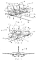
- the seat assembly 1 includes a seat 2 having a seat pan 3, a back rest 4 and arm rests 5 and which accommodates and supports a passenger P during travel. Furthermore, the seat assembly 1 includes a frame 6 upon which the seat 2 is supported, the frame 6 having legs 7 as well as one or more footings 8 which contact and attach to a floor structure F of the aircraft. In addition, the seat assembly 1 comprises a seat belt 10 having at least a first belt portion 11 which extends across a lap of the passenger P seated on the seat 2.
- a fastener element such as a buckle insert element 12, is provided at a first end region 13 of the belt portion 11 for operation by the passenger P to releasably fasten the seat belt 10 across his or her lap.
- the forces or loads imparted or transferred via the seat belt 10 during a "16g test" are illustrated as arrows R H , R V , and Rp.
- the arrow R H represents a horizontal reaction force and the arrow R V represents a vertical reaction force.
- the arrow Rp represents a passenger reaction force. Because the second end region 14 of the belt portion 11 is anchored at the footing 8 of the frame 6 or at the floor structure F of the aircraft directly, the horizontal reaction force R H and the vertical reaction force R V are essentially transferred directly to the floor structure of the aircraft. This is in contrast to the conventional seat belt arrangement shown in Figs. 2(a) and 2(b) .
- the conventional seat belt arrangement comprises a seat belt 10' having at least a first belt portion 11', an end region 14' of which is anchored to the seat frame 6' adjacent the seat pan 3'.
- the forces or loads imparted or transferred via the seat belt 10' are shown in Fig. 2(b) again as arrows R H , R V , and Rp.
- the horizontal reaction force R H and the vertical reaction force R V are transferred to the frame 6' of the conventional seat assembly 1', such that the legs 7' of the frame 6' must be designed both to withstand these loads and to transfer them to the floor structure F of the aircraft.
- the maximum forward load applied to the seat frame 6' during the 16g test would be equivalent to about 1,440 kg.
- the maximal forward load applied on the seat frame 6 could potentially be reduced from 1,440 kg to about 160 kg, and this reduction of the maximal load would then allow a corresponding reduction in the size and mass of the frame 6.
- the seat belt arrangement and seat assembly 1 shown in Figs. 1(a) and 1(b) optimize the loading paths and can lead to a significant weight reduction in the seat assembly 1 itself.
- the seat assembly 1 includes three seats 2 arranged side-by-side, with each having a seat pan 3, a back rest 4 and arm rests 5.
- the seats 2 are mounted and supported on a frame 6 which again includes legs 7 and footings 8 which engage and attach to seat rails R incorporated in the floor structure of the aircraft.
- the frame 6 also includes a transverse beam 9 which interconnects the legs 7 and carries or supports the seats 2.
- the seat assembly 1 includes a seat belt 10 associated with each respective seat 2, with each seat belt 10 having a first belt portion 11 and a second belt portion 15 that together extend across a lap of the passenger P seated on the seat 2.
- a buckle fastener element 12 is provided at a first end 13 of the first belt portion 11 and a complementary buckle fastener element 16 is provided at a first end region 17 of the second belt portion 15.
- the buckle fastener elements 12, 16 are configured for operation by the passenger P to fasten and to release the seat belt 10 across his or her lap, e.g. in a manner as is known in the art.
- a second end region 14 of the first belt portion 11 extends down to the floor structure F and is anchored at the footing 8 of the frame 6 or in the seat rail R of the floor structure F directly.
- a second end region 18 of the second belt portion 15, on the other hand, is anchored to the transverse beam 9 of the seat frame 6 next to or adjacent the respective seat pan 3.
- the second end 14, 18 of both of the first and second belt portions 11, 15 extends down to the floor structure F and is anchored at the footing 8 of the frame 6 and/or in the seat rail R of the floor structure F directly.
- each of the second ends 14, 18 of the first and second belt portions 11, 15 is provided with an anchor member 19 for rigid or secure attachment to the seat rail R.
- the embodiment of Figs. 3 and 4 also provides loading paths that can provide a significant weight reduction in the seat assembly 1, and specifically in the structure of the frame 6.
- the seat belt itself i.e. first and second belt portions
- the belt portions will typically comprise a material known and used in the art.
- the belt portions will typically comprise flat webbing or straps of woven textile material including, for example, synthetic fibres such as nylon, polypropylene, or polyester, or exceptionally high-strength materials, such as Dyneema TM or Kevlar TM .
- the fastener member and complementary fastener member attached at the first end regions of the belt portions will typically be comprised of a robust material, such as metal, e.g. an aluminium alloy.
- FIG. 5 which includes a plurality of seat belt arrangements according to the embodiments described in detail above.
- the aircraft A is configured as a commercial passenger aircraft and includes a plurality of seat assemblies 1 according to embodiments of the invention described above with reference to Figs. 3 and 4 .
- the terms “comprise”, “comprising”, “include”, “including”, “contain”, “containing”, “have”, “having”, and any variations thereof, are intended to be understood in an inclusive (i.e. non-exclusive) sense, such that the process, method, device, apparatus or system described herein is not limited to those features or parts or elements or steps recited but may include other elements, features, parts or steps not expressly listed or inherent to such process, method, article, or apparatus.
- the terms “a” and “an” used herein are intended to be understood as meaning one or more unless explicitly stated otherwise.
- the terms “first”, “second”, “third”, etc. are used merely as labels, and are not intended to impose numerical requirements on or to establish a certain ranking of importance of their objects.
Landscapes
- Engineering & Computer Science (AREA)
- Aviation & Aerospace Engineering (AREA)
- Automotive Seat Belt Assembly (AREA)
- Seats For Vehicles (AREA)
Claims (2)
- Ensemble siège d'aéronef (1) destiné à être monté sur une structure de plancher (F) d'un aéronef (A), comprenant :un rail de siège (R) conçu pour être intégré dans la structure de plancher (F) de l'aéronef (A) ;trois sièges (2) disposés côte à côte de sorte que deux sièges extérieurs et un siège central soient fournis, chaque siège (2) étant conçu pour accueillir et supporter un passager (P) pendant le voyage ;un cadre (6) sur lequel les sièges (2) sont montés et supportés, le cadre (6) comprenant des pieds (7), une poutre transversale (9) qui relie les pieds (7) et porte ou supporte les sièges (2), et des socles de base (8) conçus pour venir en prise avec et se fixer au rail de siège (R) ; etun agencement de ceinture de sécurité pour attacher les passagers (P) dans chacun des trois sièges (2) pendant le voyage, l'agencement de ceinture de sécurité comprenant :une ceinture de sécurité (10) associée à chaque siège (2) respectif comprenant au moins une première partie de ceinture (11) destinée à s'étendre sur une partie de corps du passager (P) assis sur le siège (2) et une seconde partie de ceinture (15) qui coopère avec la première partie de ceinture (11) pour s'étendre sur une partie de corps du passager (P) assis sur le siège (2) ; etun élément de fixation (12) fourni sur la première partie de ceinture (11) au niveau d'une première région d'extrémité (13) de la première partie de ceinture (11) pour être actionné par le passager (P) afin d'attacher et de libérer la ceinture de sécurité (10) à travers la partie de corps du passager (P) ; etun élément de fixation complémentaire (16) fourni au niveau d'une première région d'extrémité (17) de la seconde partie de ceinture (12), l'élément de fixation (12) fourni sur la première partie de ceinture (11) étant conçu pour coopérer avec un élément de fixation complémentaire (16) pour fixer et libérer la première partie de ceinture (11) à travers la partie de corps du passager (P) assis sur le siège (2) ;dans le cas des sièges extérieurs, une seconde région d'extrémité (14) de la première partie de ceinture (11) s'étendant vers le bas jusqu'à la structure de plancher (F) et comprenant un premier élément de fixation (19) avec lequel la ceinture de sécurité (10) est solidement fixée ou ancrée au rail de siège (R) dans la structure de plancher (F) de sorte que la seconde région d'extrémité (14) de la première partie de ceinture (11) soit ancrée au rail de siège (R) dans la structure de plancher (F) de l'aéronef, et une seconde région d'extrémité (18) de la seconde partie de ceinture (15) soit ancrée à la poutre transversale (9) du cadre de siège (6) à côté ou à proximité du siège (2) respectif ;
etdans le cas du siège central, la seconde extrémité (14, 18) des première et seconde parties de ceinture (11, 15) s'étendant vers le bas jusqu'à la structure de plancher (F) et étant ancrée dans le rail de siège (R) de la structure de plancher (F) par un second élément de fixation (19), respectivement. - Aéronef (A) comprenant au moins un ensemble siège (1) selon la revendication 1.
Priority Applications (2)
| Application Number | Priority Date | Filing Date | Title |
|---|---|---|---|
| EP14164762.8A EP2933191B1 (fr) | 2014-04-15 | 2014-04-15 | Agencement de ceinture de sécurité et ensemble siège incorporant celui-ci |
| US14/685,042 US10279914B2 (en) | 2014-04-15 | 2015-04-13 | Seat belt arrangement and seat assembly incorporating same |
Applications Claiming Priority (1)
| Application Number | Priority Date | Filing Date | Title |
|---|---|---|---|
| EP14164762.8A EP2933191B1 (fr) | 2014-04-15 | 2014-04-15 | Agencement de ceinture de sécurité et ensemble siège incorporant celui-ci |
Publications (2)
| Publication Number | Publication Date |
|---|---|
| EP2933191A1 EP2933191A1 (fr) | 2015-10-21 |
| EP2933191B1 true EP2933191B1 (fr) | 2022-01-05 |
Family
ID=50478784
Family Applications (1)
| Application Number | Title | Priority Date | Filing Date |
|---|---|---|---|
| EP14164762.8A Active EP2933191B1 (fr) | 2014-04-15 | 2014-04-15 | Agencement de ceinture de sécurité et ensemble siège incorporant celui-ci |
Country Status (2)
| Country | Link |
|---|---|
| US (1) | US10279914B2 (fr) |
| EP (1) | EP2933191B1 (fr) |
Families Citing this family (2)
| Publication number | Priority date | Publication date | Assignee | Title |
|---|---|---|---|---|
| DE102016223771A1 (de) * | 2016-11-30 | 2018-05-30 | Airbus Operations Gmbh | Flugbegleitersitz und Verfahren zur Montage eines Flugbegleitersitzes |
| FR3114779A1 (fr) * | 2020-10-07 | 2022-04-08 | Speedinnov | Siège de véhicule, notamment ferroviaire, caisse de véhicule, notamment ferroviaire, comprenant un tel siège et véhicule, notamment ferroviaire, comprenant une telle caisse |
Citations (4)
| Publication number | Priority date | Publication date | Assignee | Title |
|---|---|---|---|---|
| US4114947A (en) * | 1977-11-18 | 1978-09-19 | Chas. Olson & Sons | Detachable seat mounting for buses |
| EP0716963A1 (fr) * | 1994-12-16 | 1996-06-19 | FIAT AUTO S.p.A. | Dispositif d'ancrage d'une extrémité de ceinture de sécurité de véhicule automobile |
| EP0911227A1 (fr) * | 1997-10-23 | 1999-04-28 | Wagon Automotive | Equipement de sécurité pour passagers de véhicule automobile |
| US20070216187A1 (en) * | 2006-03-16 | 2007-09-20 | Carey Hyde | Truck bed seating apparatus |
Family Cites Families (13)
| Publication number | Priority date | Publication date | Assignee | Title |
|---|---|---|---|---|
| US2510115A (en) * | 1947-03-17 | 1950-06-06 | Jakosky Milton | Aircraft safety belt |
| US2945275A (en) * | 1956-09-27 | 1960-07-19 | Lewis L Almeter | Safety belt system construction |
| US3653713A (en) * | 1970-07-23 | 1972-04-04 | Hunting Eng Ltd | Seating structure |
| GB1332741A (en) * | 1971-04-02 | 1973-10-03 | Chrysler Uk | Motor vehicles having passenger safety harnesses |
| DE3918500A1 (de) * | 1989-06-07 | 1990-12-13 | Keiper Recaro Gmbh Co | Fahrzeugsitz, insbesondere fluggastsitz |
| US5806910A (en) * | 1996-04-30 | 1998-09-15 | Chrysler Corporation | Vehicle adjustable sling seat |
| US6293582B1 (en) * | 1996-06-14 | 2001-09-25 | Universal Propulsion Company, Inc. | Control system for air bags in different vehicle locations |
| JP4710156B2 (ja) * | 2001-03-29 | 2011-06-29 | マツダ株式会社 | 車両のシートベルト構造 |
| US7441823B2 (en) * | 2006-02-22 | 2008-10-28 | Honda Motor Co., Ltd. | Tether routing apparatus and method of using same |
| US7980590B2 (en) * | 2008-03-19 | 2011-07-19 | Amsafe, Inc. | Inflatable personal restraint systems having web-mounted inflators and associated methods of use and manufacture |
| WO2009135669A2 (fr) * | 2008-05-07 | 2009-11-12 | Zim Gmbh | Ensemble d'éléments pour rangées de sièges dans des aéronefs |
| US7862081B2 (en) * | 2008-10-09 | 2011-01-04 | Gm Global Technology Operations, Inc. | Motor vehicle safety restraint system |
| EP2767472A1 (fr) * | 2013-02-19 | 2014-08-20 | Composite Designs EU GmbH | Composant pour ensemble de siège de passager d'avion léger |
-
2014
- 2014-04-15 EP EP14164762.8A patent/EP2933191B1/fr active Active
-
2015
- 2015-04-13 US US14/685,042 patent/US10279914B2/en active Active
Patent Citations (4)
| Publication number | Priority date | Publication date | Assignee | Title |
|---|---|---|---|---|
| US4114947A (en) * | 1977-11-18 | 1978-09-19 | Chas. Olson & Sons | Detachable seat mounting for buses |
| EP0716963A1 (fr) * | 1994-12-16 | 1996-06-19 | FIAT AUTO S.p.A. | Dispositif d'ancrage d'une extrémité de ceinture de sécurité de véhicule automobile |
| EP0911227A1 (fr) * | 1997-10-23 | 1999-04-28 | Wagon Automotive | Equipement de sécurité pour passagers de véhicule automobile |
| US20070216187A1 (en) * | 2006-03-16 | 2007-09-20 | Carey Hyde | Truck bed seating apparatus |
Also Published As
| Publication number | Publication date |
|---|---|
| US10279914B2 (en) | 2019-05-07 |
| US20150291282A1 (en) | 2015-10-15 |
| EP2933191A1 (fr) | 2015-10-21 |
Similar Documents
| Publication | Publication Date | Title |
|---|---|---|
| EP2365849B1 (fr) | Système de support de soldat fixé dans un véhicule | |
| US6871876B2 (en) | Seat belt restraint system with double shoulder belts | |
| US8182043B2 (en) | Seatbelt retention device and system | |
| US6367882B1 (en) | Slip-retarding upper torso restraint harness and system | |
| US7401859B2 (en) | Deformable restraint guide for use with child restraint system | |
| US6409243B1 (en) | Safety seat for land, air and sea vehicles | |
| US9033412B2 (en) | Safety seat and method for reducing stress on an occupant of a motor vehicle | |
| US20160368404A1 (en) | Vehicle seat assembly | |
| US6179329B1 (en) | Vehicle occupant restraint harness | |
| EP2933191B1 (fr) | Agencement de ceinture de sécurité et ensemble siège incorporant celui-ci | |
| US6634710B1 (en) | Vehicle seat assembly having child seat attachments | |
| US8628135B2 (en) | Automotive vehicle seat system | |
| US20080164732A1 (en) | Automotive vehicle seat system | |
| EP2646282B1 (fr) | Dossier ayant une barre d'ancrage | |
| CA2775789C (fr) | Tendeur de sangle pour ceinture de securite | |
| US20080164685A1 (en) | Automotive vehicle seat system | |
| US9376089B1 (en) | Hinged seatbelt connection | |
| US10442393B2 (en) | Pivoting latch plate for seatbelt | |
| US20060157967A1 (en) | Seat belt system for automobile | |
| US20230061036A1 (en) | Vehicle seat | |
| US20230036452A1 (en) | Dual three-point restraint system | |
| US20120007409A1 (en) | Knee belt restraint | |
| US20240016673A1 (en) | Systems, methods, and devices for wheelchair restraint | |
| CN114466772B (zh) | 包括用于固定安全带装置的固定系统的车辆 | |
| CN215155699U (zh) | 用于客运运输工具的椅套和椅套组件 |
Legal Events
| Date | Code | Title | Description |
|---|---|---|---|
| PUAI | Public reference made under article 153(3) epc to a published international application that has entered the european phase |
Free format text: ORIGINAL CODE: 0009012 |
|
| AK | Designated contracting states |
Kind code of ref document: A1 Designated state(s): AL AT BE BG CH CY CZ DE DK EE ES FI FR GB GR HR HU IE IS IT LI LT LU LV MC MK MT NL NO PL PT RO RS SE SI SK SM TR |
|
| AX | Request for extension of the european patent |
Extension state: BA ME |
|
| 17P | Request for examination filed |
Effective date: 20160419 |
|
| RBV | Designated contracting states (corrected) |
Designated state(s): AL AT BE BG CH CY CZ DE DK EE ES FI FR GB GR HR HU IE IS IT LI LT LU LV MC MK MT NL NO PL PT RO RS SE SI SK SM TR |
|
| STAA | Information on the status of an ep patent application or granted ep patent |
Free format text: STATUS: EXAMINATION IS IN PROGRESS |
|
| 17Q | First examination report despatched |
Effective date: 20181220 |
|
| STAA | Information on the status of an ep patent application or granted ep patent |
Free format text: STATUS: EXAMINATION IS IN PROGRESS |
|
| GRAP | Despatch of communication of intention to grant a patent |
Free format text: ORIGINAL CODE: EPIDOSNIGR1 |
|
| STAA | Information on the status of an ep patent application or granted ep patent |
Free format text: STATUS: GRANT OF PATENT IS INTENDED |
|
| INTG | Intention to grant announced |
Effective date: 20211008 |
|
| GRAS | Grant fee paid |
Free format text: ORIGINAL CODE: EPIDOSNIGR3 |
|
| GRAA | (expected) grant |
Free format text: ORIGINAL CODE: 0009210 |
|
| STAA | Information on the status of an ep patent application or granted ep patent |
Free format text: STATUS: THE PATENT HAS BEEN GRANTED |
|
| AK | Designated contracting states |
Kind code of ref document: B1 Designated state(s): AL AT BE BG CH CY CZ DE DK EE ES FI FR GB GR HR HU IE IS IT LI LT LU LV MC MK MT NL NO PL PT RO RS SE SI SK SM TR |
|
| REG | Reference to a national code |
Ref country code: GB Ref legal event code: FG4D |
|
| REG | Reference to a national code |
Ref country code: CH Ref legal event code: EP |
|
| REG | Reference to a national code |
Ref country code: AT Ref legal event code: REF Ref document number: 1460325 Country of ref document: AT Kind code of ref document: T Effective date: 20220115 |
|
| REG | Reference to a national code |
Ref country code: DE Ref legal event code: R096 Ref document number: 602014081989 Country of ref document: DE |
|
| REG | Reference to a national code |
Ref country code: IE Ref legal event code: FG4D |
|
| REG | Reference to a national code |
Ref country code: LT Ref legal event code: MG9D |
|
| REG | Reference to a national code |
Ref country code: NL Ref legal event code: MP Effective date: 20220105 |
|
| REG | Reference to a national code |
Ref country code: AT Ref legal event code: MK05 Ref document number: 1460325 Country of ref document: AT Kind code of ref document: T Effective date: 20220105 |
|
| PG25 | Lapsed in a contracting state [announced via postgrant information from national office to epo] |
Ref country code: NL Free format text: LAPSE BECAUSE OF FAILURE TO SUBMIT A TRANSLATION OF THE DESCRIPTION OR TO PAY THE FEE WITHIN THE PRESCRIBED TIME-LIMIT Effective date: 20220105 |
|
| PG25 | Lapsed in a contracting state [announced via postgrant information from national office to epo] |
Ref country code: SE Free format text: LAPSE BECAUSE OF FAILURE TO SUBMIT A TRANSLATION OF THE DESCRIPTION OR TO PAY THE FEE WITHIN THE PRESCRIBED TIME-LIMIT Effective date: 20220105 Ref country code: RS Free format text: LAPSE BECAUSE OF FAILURE TO SUBMIT A TRANSLATION OF THE DESCRIPTION OR TO PAY THE FEE WITHIN THE PRESCRIBED TIME-LIMIT Effective date: 20220105 Ref country code: PT Free format text: LAPSE BECAUSE OF FAILURE TO SUBMIT A TRANSLATION OF THE DESCRIPTION OR TO PAY THE FEE WITHIN THE PRESCRIBED TIME-LIMIT Effective date: 20220505 Ref country code: NO Free format text: LAPSE BECAUSE OF FAILURE TO SUBMIT A TRANSLATION OF THE DESCRIPTION OR TO PAY THE FEE WITHIN THE PRESCRIBED TIME-LIMIT Effective date: 20220405 Ref country code: LT Free format text: LAPSE BECAUSE OF FAILURE TO SUBMIT A TRANSLATION OF THE DESCRIPTION OR TO PAY THE FEE WITHIN THE PRESCRIBED TIME-LIMIT Effective date: 20220105 Ref country code: HR Free format text: LAPSE BECAUSE OF FAILURE TO SUBMIT A TRANSLATION OF THE DESCRIPTION OR TO PAY THE FEE WITHIN THE PRESCRIBED TIME-LIMIT Effective date: 20220105 Ref country code: ES Free format text: LAPSE BECAUSE OF FAILURE TO SUBMIT A TRANSLATION OF THE DESCRIPTION OR TO PAY THE FEE WITHIN THE PRESCRIBED TIME-LIMIT Effective date: 20220105 Ref country code: BG Free format text: LAPSE BECAUSE OF FAILURE TO SUBMIT A TRANSLATION OF THE DESCRIPTION OR TO PAY THE FEE WITHIN THE PRESCRIBED TIME-LIMIT Effective date: 20220405 |
|
| PG25 | Lapsed in a contracting state [announced via postgrant information from national office to epo] |
Ref country code: PL Free format text: LAPSE BECAUSE OF FAILURE TO SUBMIT A TRANSLATION OF THE DESCRIPTION OR TO PAY THE FEE WITHIN THE PRESCRIBED TIME-LIMIT Effective date: 20220105 Ref country code: LV Free format text: LAPSE BECAUSE OF FAILURE TO SUBMIT A TRANSLATION OF THE DESCRIPTION OR TO PAY THE FEE WITHIN THE PRESCRIBED TIME-LIMIT Effective date: 20220105 Ref country code: GR Free format text: LAPSE BECAUSE OF FAILURE TO SUBMIT A TRANSLATION OF THE DESCRIPTION OR TO PAY THE FEE WITHIN THE PRESCRIBED TIME-LIMIT Effective date: 20220406 Ref country code: FI Free format text: LAPSE BECAUSE OF FAILURE TO SUBMIT A TRANSLATION OF THE DESCRIPTION OR TO PAY THE FEE WITHIN THE PRESCRIBED TIME-LIMIT Effective date: 20220105 Ref country code: AT Free format text: LAPSE BECAUSE OF FAILURE TO SUBMIT A TRANSLATION OF THE DESCRIPTION OR TO PAY THE FEE WITHIN THE PRESCRIBED TIME-LIMIT Effective date: 20220105 |
|
| PG25 | Lapsed in a contracting state [announced via postgrant information from national office to epo] |
Ref country code: IS Free format text: LAPSE BECAUSE OF FAILURE TO SUBMIT A TRANSLATION OF THE DESCRIPTION OR TO PAY THE FEE WITHIN THE PRESCRIBED TIME-LIMIT Effective date: 20220505 |
|
| REG | Reference to a national code |
Ref country code: DE Ref legal event code: R097 Ref document number: 602014081989 Country of ref document: DE |
|
| PG25 | Lapsed in a contracting state [announced via postgrant information from national office to epo] |
Ref country code: SM Free format text: LAPSE BECAUSE OF FAILURE TO SUBMIT A TRANSLATION OF THE DESCRIPTION OR TO PAY THE FEE WITHIN THE PRESCRIBED TIME-LIMIT Effective date: 20220105 Ref country code: SK Free format text: LAPSE BECAUSE OF FAILURE TO SUBMIT A TRANSLATION OF THE DESCRIPTION OR TO PAY THE FEE WITHIN THE PRESCRIBED TIME-LIMIT Effective date: 20220105 Ref country code: RO Free format text: LAPSE BECAUSE OF FAILURE TO SUBMIT A TRANSLATION OF THE DESCRIPTION OR TO PAY THE FEE WITHIN THE PRESCRIBED TIME-LIMIT Effective date: 20220105 Ref country code: EE Free format text: LAPSE BECAUSE OF FAILURE TO SUBMIT A TRANSLATION OF THE DESCRIPTION OR TO PAY THE FEE WITHIN THE PRESCRIBED TIME-LIMIT Effective date: 20220105 Ref country code: DK Free format text: LAPSE BECAUSE OF FAILURE TO SUBMIT A TRANSLATION OF THE DESCRIPTION OR TO PAY THE FEE WITHIN THE PRESCRIBED TIME-LIMIT Effective date: 20220105 Ref country code: CZ Free format text: LAPSE BECAUSE OF FAILURE TO SUBMIT A TRANSLATION OF THE DESCRIPTION OR TO PAY THE FEE WITHIN THE PRESCRIBED TIME-LIMIT Effective date: 20220105 |
|
| PLBE | No opposition filed within time limit |
Free format text: ORIGINAL CODE: 0009261 |
|
| STAA | Information on the status of an ep patent application or granted ep patent |
Free format text: STATUS: NO OPPOSITION FILED WITHIN TIME LIMIT |
|
| PG25 | Lapsed in a contracting state [announced via postgrant information from national office to epo] |
Ref country code: AL Free format text: LAPSE BECAUSE OF FAILURE TO SUBMIT A TRANSLATION OF THE DESCRIPTION OR TO PAY THE FEE WITHIN THE PRESCRIBED TIME-LIMIT Effective date: 20220105 |
|
| REG | Reference to a national code |
Ref country code: CH Ref legal event code: PL |
|
| 26N | No opposition filed |
Effective date: 20221006 |
|
| REG | Reference to a national code |
Ref country code: BE Ref legal event code: MM Effective date: 20220430 |
|
| PG25 | Lapsed in a contracting state [announced via postgrant information from national office to epo] |
Ref country code: MC Free format text: LAPSE BECAUSE OF FAILURE TO SUBMIT A TRANSLATION OF THE DESCRIPTION OR TO PAY THE FEE WITHIN THE PRESCRIBED TIME-LIMIT Effective date: 20220105 Ref country code: LU Free format text: LAPSE BECAUSE OF NON-PAYMENT OF DUE FEES Effective date: 20220415 Ref country code: LI Free format text: LAPSE BECAUSE OF NON-PAYMENT OF DUE FEES Effective date: 20220430 Ref country code: CH Free format text: LAPSE BECAUSE OF NON-PAYMENT OF DUE FEES Effective date: 20220430 |
|
| PG25 | Lapsed in a contracting state [announced via postgrant information from national office to epo] |
Ref country code: SI Free format text: LAPSE BECAUSE OF FAILURE TO SUBMIT A TRANSLATION OF THE DESCRIPTION OR TO PAY THE FEE WITHIN THE PRESCRIBED TIME-LIMIT Effective date: 20220105 Ref country code: BE Free format text: LAPSE BECAUSE OF NON-PAYMENT OF DUE FEES Effective date: 20220430 |
|
| PG25 | Lapsed in a contracting state [announced via postgrant information from national office to epo] |
Ref country code: IE Free format text: LAPSE BECAUSE OF NON-PAYMENT OF DUE FEES Effective date: 20220415 |
|
| PG25 | Lapsed in a contracting state [announced via postgrant information from national office to epo] |
Ref country code: IT Free format text: LAPSE BECAUSE OF FAILURE TO SUBMIT A TRANSLATION OF THE DESCRIPTION OR TO PAY THE FEE WITHIN THE PRESCRIBED TIME-LIMIT Effective date: 20220105 |
|
| PGFP | Annual fee paid to national office [announced via postgrant information from national office to epo] |
Ref country code: FR Payment date: 20230424 Year of fee payment: 10 Ref country code: DE Payment date: 20230420 Year of fee payment: 10 |
|
| PGFP | Annual fee paid to national office [announced via postgrant information from national office to epo] |
Ref country code: GB Payment date: 20230419 Year of fee payment: 10 |
|
| PG25 | Lapsed in a contracting state [announced via postgrant information from national office to epo] |
Ref country code: HU Free format text: LAPSE BECAUSE OF FAILURE TO SUBMIT A TRANSLATION OF THE DESCRIPTION OR TO PAY THE FEE WITHIN THE PRESCRIBED TIME-LIMIT; INVALID AB INITIO Effective date: 20140415 |
|
| PG25 | Lapsed in a contracting state [announced via postgrant information from national office to epo] |
Ref country code: MK Free format text: LAPSE BECAUSE OF FAILURE TO SUBMIT A TRANSLATION OF THE DESCRIPTION OR TO PAY THE FEE WITHIN THE PRESCRIBED TIME-LIMIT Effective date: 20220105 Ref country code: CY Free format text: LAPSE BECAUSE OF FAILURE TO SUBMIT A TRANSLATION OF THE DESCRIPTION OR TO PAY THE FEE WITHIN THE PRESCRIBED TIME-LIMIT Effective date: 20220105 |