EP2933047A1 - Schneidwerkzeug für die spanabhebende Bearbeitung und Schneide-Wechselvorrichtung dafür - Google Patents
Schneidwerkzeug für die spanabhebende Bearbeitung und Schneide-Wechselvorrichtung dafür Download PDFInfo
- Publication number
- EP2933047A1 EP2933047A1 EP14164902.0A EP14164902A EP2933047A1 EP 2933047 A1 EP2933047 A1 EP 2933047A1 EP 14164902 A EP14164902 A EP 14164902A EP 2933047 A1 EP2933047 A1 EP 2933047A1
- Authority
- EP
- European Patent Office
- Prior art keywords
- cutting edge
- exchange mechanism
- ejector
- cutting
- cutting insert
- Prior art date
- Legal status (The legal status is an assumption and is not a legal conclusion. Google has not performed a legal analysis and makes no representation as to the accuracy of the status listed.)
- Granted
Links
- 238000005520 cutting process Methods 0.000 title claims abstract description 145
- 238000003754 machining Methods 0.000 title claims abstract description 5
- 230000007246 mechanism Effects 0.000 claims abstract description 49
- 230000006835 compression Effects 0.000 claims abstract description 10
- 238000007906 compression Methods 0.000 claims abstract description 10
- 230000001131 transforming effect Effects 0.000 claims abstract description 3
- 238000003801 milling Methods 0.000 description 6
- 239000011796 hollow space material Substances 0.000 description 5
- 238000004519 manufacturing process Methods 0.000 description 4
- 230000000630 rising effect Effects 0.000 description 4
- 239000012530 fluid Substances 0.000 description 3
- 238000013459 approach Methods 0.000 description 2
- 230000015572 biosynthetic process Effects 0.000 description 2
- 238000005755 formation reaction Methods 0.000 description 2
- 238000003825 pressing Methods 0.000 description 2
- 235000004522 Pentaglottis sempervirens Nutrition 0.000 description 1
- 239000007788 liquid Substances 0.000 description 1
- 230000007774 longterm Effects 0.000 description 1
- 238000012986 modification Methods 0.000 description 1
- 230000004048 modification Effects 0.000 description 1
- 230000001921 mouthing effect Effects 0.000 description 1
- 230000002093 peripheral effect Effects 0.000 description 1
Images


Classifications
-
- B—PERFORMING OPERATIONS; TRANSPORTING
- B23—MACHINE TOOLS; METAL-WORKING NOT OTHERWISE PROVIDED FOR
- B23C—MILLING
- B23C5/00—Milling-cutters
- B23C5/16—Milling-cutters characterised by physical features other than shape
- B23C5/20—Milling-cutters characterised by physical features other than shape with removable cutter bits or teeth or cutting inserts
- B23C5/22—Securing arrangements for bits or teeth or cutting inserts
- B23C5/24—Securing arrangements for bits or teeth or cutting inserts adjustable
-
- B—PERFORMING OPERATIONS; TRANSPORTING
- B23—MACHINE TOOLS; METAL-WORKING NOT OTHERWISE PROVIDED FOR
- B23C—MILLING
- B23C5/00—Milling-cutters
- B23C5/16—Milling-cutters characterised by physical features other than shape
- B23C5/20—Milling-cutters characterised by physical features other than shape with removable cutter bits or teeth or cutting inserts
- B23C5/22—Securing arrangements for bits or teeth or cutting inserts
- B23C5/2204—Securing arrangements for bits or teeth or cutting inserts with cutting inserts clamped against the walls of the recess in the cutter body by a clamping member acting upon the wall of a hole in the insert
- B23C5/2208—Securing arrangements for bits or teeth or cutting inserts with cutting inserts clamped against the walls of the recess in the cutter body by a clamping member acting upon the wall of a hole in the insert for plate-like cutting inserts
- B23C5/2213—Securing arrangements for bits or teeth or cutting inserts with cutting inserts clamped against the walls of the recess in the cutter body by a clamping member acting upon the wall of a hole in the insert for plate-like cutting inserts having a special shape
-
- B—PERFORMING OPERATIONS; TRANSPORTING
- B23—MACHINE TOOLS; METAL-WORKING NOT OTHERWISE PROVIDED FOR
- B23C—MILLING
- B23C5/00—Milling-cutters
- B23C5/02—Milling-cutters characterised by the shape of the cutter
- B23C5/06—Face-milling cutters, i.e. having only or primarily a substantially flat cutting surface
-
- B—PERFORMING OPERATIONS; TRANSPORTING
- B23—MACHINE TOOLS; METAL-WORKING NOT OTHERWISE PROVIDED FOR
- B23C—MILLING
- B23C5/00—Milling-cutters
- B23C5/16—Milling-cutters characterised by physical features other than shape
- B23C5/20—Milling-cutters characterised by physical features other than shape with removable cutter bits or teeth or cutting inserts
- B23C5/22—Securing arrangements for bits or teeth or cutting inserts
- B23C5/2239—Securing arrangements for bits or teeth or cutting inserts with cutting inserts clamped by a clamping member acting almost perpendicular on the cutting face
- B23C5/2252—Securing arrangements for bits or teeth or cutting inserts with cutting inserts clamped by a clamping member acting almost perpendicular on the cutting face for plate-like cutting inserts fitted on an intermediate carrier, e.g. shank fixed in the cutter body
-
- B—PERFORMING OPERATIONS; TRANSPORTING
- B23—MACHINE TOOLS; METAL-WORKING NOT OTHERWISE PROVIDED FOR
- B23B—TURNING; BORING
- B23B2205/00—Fixation of cutting inserts in holders
- B23B2205/18—Systems for indexing the cutting insert automatically
-
- B—PERFORMING OPERATIONS; TRANSPORTING
- B23—MACHINE TOOLS; METAL-WORKING NOT OTHERWISE PROVIDED FOR
- B23C—MILLING
- B23C2200/00—Details of milling cutting inserts
- B23C2200/16—Supporting or bottom surfaces
- B23C2200/168—Supporting or bottom surfaces with features related to indexing
-
- B—PERFORMING OPERATIONS; TRANSPORTING
- B23—MACHINE TOOLS; METAL-WORKING NOT OTHERWISE PROVIDED FOR
- B23C—MILLING
- B23C2200/00—Details of milling cutting inserts
- B23C2200/36—Other features of the milling insert not covered by B23C2200/04 - B23C2200/32
- B23C2200/363—Lines for indexing round inserts
-
- B—PERFORMING OPERATIONS; TRANSPORTING
- B23—MACHINE TOOLS; METAL-WORKING NOT OTHERWISE PROVIDED FOR
- B23C—MILLING
- B23C2210/00—Details of milling cutters
- B23C2210/16—Fixation of inserts or cutting bits in the tool
- B23C2210/161—Elastically deformable clamping members
-
- B—PERFORMING OPERATIONS; TRANSPORTING
- B23—MACHINE TOOLS; METAL-WORKING NOT OTHERWISE PROVIDED FOR
- B23C—MILLING
- B23C2210/00—Details of milling cutters
- B23C2210/16—Fixation of inserts or cutting bits in the tool
- B23C2210/163—Indexing
Definitions
- this invention relates to a tool intended for chip removing machining and of the type that comprises a basic body and a replaceable cutting insert, which is indexable by means of a cutting edge exchange mechanism, in which there is included a long narrow ejector, which in a front part has an attachment for the cutting insert and interacts with turning means for transforming a rectilinear, axial movement into a simultaneous turning of the same.
- the invention also relates to an autonomous cutting edge exchange mechanism as such.
- a cutting tool of the type initially mentioned is previously known by US 4024777 . More precisely, this document describes and exemplifies a turning tool of the type that, in addition to a holder or bar, includes an indexable cutting insert having a parallelepipedic shape, which has four alternately individually usable cutting edges, and which can be rotationally secured in a seat with two side support surfaces perpendicular to each other.
- This cutting insert may be detachably mounted in an attachment on a front part of a shaft included in a device, and which turns in connection with the same being rectilinearly thrust outward to a position in which the cutting insert has left the seat.
- the shaft includes a piston, which is sealed against the inside of a cylindrical boring, in which the piston is movable back and forth.
- the boring forms a pressure fluid cylinder, which is divided into a plus chamber and a minus chamber to and from which a pressure fluid (e.g., liquid or gas) can be supplied and evacuated, respectively, for either thrusting out the cutting insert and indexing the same, or bringing the same back to the operative position in the seat.
- a pressure fluid e.g., liquid or gas
- Turning of the shaft is provided for by a fixed guide pin, which projects into the boring and the piston and engages the gaps between a number of front teeth having obliquely cut end edge surfaces, with which obliquely cut edge surfaces of a rear set of teeth included in the same piston interact.
- a disadvantage of this known tool is that the clamping of the cutting insert in the appurtenant seat is unreliable and it is a problem to accommodate tolerances for the fitting of the cutting insert into the seat.
- Another disadvantage is that the tool is complex and expensive to manufacture.
- a primary object of the invention is to provide a tool formed with a cutting edge exchange mechanism, and an autonomous cutting edge exchange mechanism, which guarantees a simple and quick indexing of the cutting insert, and a long-term reliable fixation of the cutting insert in its operative state.
- the invention aims at allowing use of a cutting edge exchange mechanism not only in stationary tools, such as turning tools, but also in movable ones, in particular rotatable milling tools.
- the cutting edge exchange mechanism comprises a stop collar, which is fixedly anchorable in relation to the basic body and through which the ejector is movable back and forth, as well as a carrier included in a rear part of the ejector, between the carrier and the stop collar, there being arranged a compressible force generator, which aims at distancing the first-mentioned one from the last-mentioned one.
- the cutting edge exchange mechanism having been provided with a force generator, which is formed in such a way that it aims at pressing apart the carrier from the stop collar, the force generator will aim at pressing the cutting insert situated in its outer end toward the stop collar so that the cutting insert reliably and distinctly can be pushed against a seat of the basic body arranged therefor.
- the force generator being of the compressible type, a simple manoeuvring is allowed by the fact that only one compressing power needs to be provided and its function becomes reliable. By thrusting out the ejector against the action of the spring, indexing as well as replacement of the individual cutting insert can be carried out in a simple, convenient, and fast way.
- the invention is based on the idea of forming a cutting tool of the type that includes a cutting edge exchange mechanism in such a way that indexing and/or replacement of one or more cutting inserts can be carried out fast and easily, at the same time as the fixation of the cutting insert in the operative position becomes reliable.
- the cutting edge exchange mechanism uses a compression spring or another compressible force supplying member, e.g., a gas spring, which by great spring force can hold the ejector retracted in a position in which the cutting insert distinctly is fixedly pressed in an appurtenant seat.
- a suitable accessory e.g., a mandrel, may be utilized for overcoming the spring force and thrusting out the ejector during simultaneous turning of the same toward a new index position for the cutting insert.
- the task to carry out a turning motion along an arc angle determined by the number of cutting edges per cutting insert can be provided in many different ways.
- the task is divided between, on one hand, sets of obliquely cut teeth of the proper cutting edge exchange mechanism, and, on the other hand, sets of male-like cogs in a seat and of the cutting insert.
- a final turning of the cutting insert and the ejector can be carried out by the sloping flank surfaces sliding in relation to each other until a pair of steeply rising flank surfaces are urged against each other.
- the tool is a milling cutter (or another rotatable tool)
- each one of a plurality of cutting inserts can be mounted on each an ejector, which in one and the same single operation can be thrust out and simultaneously turned in order to assume a new index position.
- the last-mentioned facts mean that the known device in practice only is suitable for use in stationary tools, such as turning tools, but not in such rotatable tools as milling cutters.
- the tolerance chain between the locking pin that determines the turning position of the cutting insert, and the side support surfaces that are included in the seat of the cutting insert becomes long and awkward, involving that the fitting in of the cutting insert in the seat runs the risk of becoming imprecise.
- the stop collar as well as the carrier is included in a pair of sleeves, which also include cylinder walls, which are radially separated from the ejector, the force generator being placed between the ejector and the cylinder walls, besides which the turning means for turning the ejector during its rectilinear projection are included in the cylinder walls of the sleeves.
- the turning means requisite for the turning of the ejector are integrated with walls, which are simple to manufacture and which in a reliable way retain the spring in desired position.
- the turning means may consist of two sets of pointed teeth pointing at each other, which are formed in the cylinder walls and each one of which includes an obliquely cut edge surface, which extends between a point and a tooth gap bottom. In such a way, the manufacture of the cutting edge exchange mechanism is facilitated.
- the stop collar included in the cutting edge exchange mechanism, includes a seat, intended for the receipt of the cutting insert, in the form of a gear rim having tangentially spaced-apart cogs, which include a shallowly tilted flank surface as well as a steeply tilted flank surface, which together delimit an individual gash, besides which the cutting insert includes a second gear rim having analogous cogs arranged to engage the gashes of the first gear rim.
- the force generator is a compression spring, such as, for instance, a helical spring. This is advantageously a simple and reliable component.
- the cutting edge exchange mechanism is partly arranged in a bore in the tool body, at least the force generator being positioned in the bore. In this way, it is possible to protect the force generator from chips inside the basic body.
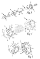
- the invention is shown primarily applied to a milling tool in the form of a face mill, which is illustrated in Figs. 1-20 . It is, however, also possible to use the present invention in another suitable chip removing tool, for example a turning tool.
- a milling cutter which includes a basic or tool body 1, and a plurality of replaceable cutting inserts 2.
- the basic body 1 includes a pair of opposite front and back, respectively, sides (may also be denominated front and rear ends) 3, 4 and a peripheral surface or envelope surface 5, which extends between the same. Between the front and back sides 3, 4, a centre axis C1 extends, on which the tool body is rotatable.
- the envelope surface 5 forms a geometrical surface of revolution on the centre axis.
- the number of cutting inserts 2 amounts to ten.
- the pitch between the cutting inserts is uniform and amounts to 36°.
- Fig. 1 one of the cutting inserts 2 is shown exploded away from the tool body 1 together with a cutting edge exchange mechanism, in its entirety designated 6, and a screw 7.
- the other nine cutting inserts are shown in positions in which they are operative and in engagement with the appurtenant seats.
- the basic body 1 includes a central hollow space 8, which in the example is a through hole, i.e., a hole mouthing in the front side 3 as well as the back side 4.
- the hole is delimited by an internal limiting surface 9 in the form of one or more cylinder surfaces assumed to be generated by straight generatrices, which are parallel to the centre axis C1.
- a groove 11 is countersunk in the back side 4 of the basic body. Via this groove, the requisite torque can be transferred to the basic body from a driving source.
- a plurality of bores 10 having the purpose of housing the cutting edge exchange mechanisms 6 as well as the appurtenant cutting inserts 2.
- Centre axes of said bores 10 are designated C2 and oriented essentially radially in relation to the centre axis C1 of the basic body, more precisely so far that they radiate equiangularly from the last-mentioned one.
- Figs. 3-5 which on an enlarged scale illustrate the structure of the individual cutting edge exchange mechanism 6.
- Components of this mechanism comprise a pair of generally cylindrical sleeves, a first one of which is designated 12 and a second one 13. Between these sleeves, a compressible force generator 14 acts in the form of a simple, mechanical compression spring, viz. a screw compression spring.
- the sleeve 12 forms a radially outer sleeve in the basic body, while the sleeve 13 forms a radially inner sleeve.
- the outer sleeve 12 (see Figs. 4 and 10 ) includes, on one hand, a front, ring-shaped stop collar 15 for the spring 14, and, on the other hand, a rear cylinder wall 16.
- the stop collar 15 has an inner diameter that is smaller than the inner diameter of the cylinder wall 16. In such a way, a circumferential shoulder surface 17 is obtained, against which the outer end of the spring 14 can be urged.
- a set of teeth 18 is formed, which points rearward and each one includes, on one hand, a first, obliquely cut edge surface 19, and, on the other hand, a second edge surface 20, which is straight and is running axially in the present example.
- the obliquely cut edge surface 19 extends from a tooth point 21a to a bottom 21b of the individual tooth gap. The gradient of the edge surface 19 from the bottom 21b to the tooth point 21a is essentially even.
- the inner sleeve 13 includes front and rear parts 22, 23, the front one 22 of which is a cylinder wall having teeth 24, while the rear one 23 serves as a carrier.
- the rear part or the carrier 23 there is included a hole 25 having a female thread.
- the diameter of the hole 25 is smaller than the inner diameter of the cylinder wall 22.
- a ring-shaped shoulder surface 26 is formed, against which the inner end of the spring 14 can abut.
- the teeth 24 include an obliquely cut edge surface 27, and a straight, axially running edge surface 28. Each such edge surface extends between a point 29a and a tooth gap bottom 29b.
- a conical surface 31 forms a rearward tapering termination of the carrier 23.
- a long narrow rod 32 (see Fig. 3 ), which in a rear end includes a male thread 33, and in a front end a female thread 34, which in the example is formed in a head 35.
- the rod 32 and the carrier 23 form an ejector, which is rectilinearly movable in relation to the stop collar 15.
- the cutting inserts 2 are double-sided and formed with six alternately individually usable cutting edges 36 along each one of two opposite sides, which may be turned either outward or inward in relation to the basic body 1. For this reason, the number of teeth 18, 24 of the sleeves 12, 13 amounts to exactly six.
- the outer sleeve 12 of the cutting edge exchange mechanism 6 is fixedly anchored in relation to the basic body 1. More precisely, the sleeve 12 is rotationally secured by means of a pair of flat surfaces 38, which abut against flat surfaces 39 (see Fig. 16 ) in the present bore 10.
- the bore generally designated 10 includes three different, cylindrical sections 40, 41, 42 of different diameters.
- An inner section 40 which mouths in the inner surface 9 of the hollow space 8 via a mouth 43, has a smallest (internal) diameter.
- An intermediate section 41 has a somewhat greater diameter. In such a way, a ring-shaped shoulder 44, narrow per se, but still marked, is formed between the sections 40 and 41.
- the outermost section 42 has a considerably greater diameter than the intermediate section 41. Therefore, a comparatively wide shoulder surface 45 is formed between the sections 41 and 42.
- the radially external section 42 in the bore 10 has a sufficiently large radius and a sufficiently large depth to accommodate the major part of the cutting insert 2. See Fig. 17 .
- the sleeve 12 includes an external, narrow shoulder 46, which can be urged against the shoulder 44, when the sleeve 12 is mounted in the bore 10.
- the wide shoulder surface 45 see Fig. 16
- there mouth two threaded holes 47 having a conical part surface 48, in the extension of which there extends a chute 49 (having a semicylindrical shape).
- Analogous chutes 50 as well as conical part surfaces 51 are also formed in the external, convex part surfaces of the sleeve 12 (see Fig. 5 ).
- the two screws 52 shown in Figs. 3 and 15 are intended to be tightened in the threaded holes 47, the heads 53 being urged against the conical part surfaces 48, 51 to secure the sleeve 12 axially in the appurtenant bore 10.
- the sleeve is rotationally secured by means of the pairs of flat surfaces 38, 39.
- the sleeve 12 is, in its mounted state, fixedly anchored non-axially and rotation-angularly.
- the carrier 23, included in the movable sleeve 13, is in the example fixedly connected with the rod 32, more precisely via a threaded joint in the form of the male thread 33 and the female thread 25.
- a threaded joint in the form of the male thread 33 and the female thread 25.
- other joints may be used. It is even possible to arrange the carrier 23 rotatable in relation to the rod on the assumption that the carrier is axially secured in relation to the same.
- the described cutting edge exchange mechanism is autonomous so far that the two sleeves as well as the ejector rod are manufactured in the form of an independent unit, which can be mounted in the appurtenant bore 10 (by means of the screws 52). As is seen later, however, parts of the mechanism may be integrated with the basic body as such.
- a seat, in its entirety designated 54, for the cutting insert 2 is formed in the outer sleeve 12, more precisely in the outside of the stop collar 15 thereof (see also Fig. 10 ).
- This seat 54 includes a plurality of male members or cogs 55, which are included in a rim and between which there are female-like recesses or gashes 56.
- the number of cogs and gashes, respectively corresponds with the number of cutting edges of the cutting insert 2, i.e., in the example six. Therefore, for geometrically axiomatic reasons, the pitch angle ⁇ between the cogs amounts to 60°.
- the individual gash 56 is delimited by two opposite flank surfaces, viz. a flatly leaning flank surface 57 and a flank surface 58 having a relatively steeply rising flank angle. In practice, the flank angle of the surface 57 may amount to approx. 45°, while the flank angle of the surface 58 may approach 90°.
- an analogous rim 59 of cogs 60 having the same pitch angle (60°) as the cogs 55. These are separated by gashes 61, and include a flatly leaning flank surface 62 as well as a steeply rising flank surface 63. When the gear rims engage each other, the cogs do not bottom in the gashes, i.e., only the flank surfaces 57/62 and 58/63 contact each other.
- a cutting insert 2 is attached to the second end of the rod 32 by a screw 7 extending through a central hole in the cutting insert 2 and being screwed in in the female thread 34 of the rod.
- the individual, flat flank surface 57 and 62 occupies only a smaller part of the 60° arch that is utilized for each individual cog formation as viewed in plane elevation.
- the arc angle of the flat flank surface may amount to around 5°.
- Fig. 17 the cutting inserts 2 are shown in their operative positions.
- the spring 14 of the individual cutting edge exchange mechanism holds the inner, movable sleeve 13 spaced apart from the fixed, outer sleeve 12.
- the internal gear rim 59 of the cutting insert 2 is in engagement with the outward facing gear rim 54 that forms a seat and is included in the sleeve 12.
- the steep flanks 58, 63 of the cogs are in contact with each other. These are placed in such a way that they carry the cutting forces that act against the operative cutting edge of the cutting insert, whereby turning of the cutting insert is prevented.
- the cutting insert is maximally spaced apart from the sleeve 12, besides which all teeth 18 and 24, respectively, completely engage the interacting the tooth gaps.
- the straight edge surfaces 20 and 28 are having contact with each other, as shown by the arrows D.
- the sleeve 13 can no longer turn.
- the ejector as well as the cutting insert having turned approx. 55° from the position according to Fig. 20a to the position according to Fig. 20e (provided that the tooth points 21a, 29a should overlap each other at an arc angle of 5°).
- the mandrel 70 is removed from the hollow space 8.
- the ejectors 32 are disengaged and subjected to the action of the springs 14.
- the individual ejector is given an axial movement in the direction of the arrow E only.
- the gear rim 59 of the cutting insert begins to engage the fixed gear rim that forms the seat 54. More precisely, the cogs 60 will engage the gashes 56, and vice versa.
- An advantage of the invention is that it allows a simple and quick indexing of one or more cutting inserts, the cutting insert after indexing distinctly being fixedly pressed in the appurtenant seat by means of a compression spring, which is well protected inside the basic body.
- the cutting edge exchange mechanism made as an autonomous unit can be mounted in any tool irrespective of whether these are stationary or movable.
- the inner ends of the ejectors may stick inward in a hollow space common to all ejectors, from which they can be ejected in a single, centrally controlled operation, in which the cutting inserts are mass indexed.
- Fig. 21 shows how the invention also can be applied to a tool in the form of a turning tool having only one cutting insert 2.
- the cutting insert is round and double-sided as well as includes a single endless cutting edge 36 along each one of the two opposite sides of the cutting insert.
- the cutting edge exchange mechanism 6 includes an ejector, which is turnable in steps to six different positions, wherein a gear rim 54 serves as a seat including six tangentially spaced-apart cogs.
- a gear rim 59 included in the cutting insert includes six cogs.
- the cutting insert can be indexed to six different positions, in each one of which a sixth of the circumference of the cutting edge is utilized, i.e., a 60° arc angle.
- the invention is not limited to the embodiments exemplified in the drawings.
- the compressible force generator may be other compression springs than exactly a screw compression spring, e.g., cup springs, gas springs, etc.
- the means to compulsorily turn the ejector as well as the cutting insert in connection with ejection do not necessarily need to be obliquely cut teeth in cylinder walls of the kind described. Thus, it is feasible to use thread formations having a large pitch.
Landscapes
- Engineering & Computer Science (AREA)
- Mechanical Engineering (AREA)
- Drilling Tools (AREA)
- Milling Processes (AREA)
- Automatic Tool Replacement In Machine Tools (AREA)
- Cutting Tools, Boring Holders, And Turrets (AREA)
Priority Applications (8)
| Application Number | Priority Date | Filing Date | Title |
|---|---|---|---|
| EP14164902.0A EP2933047B1 (de) | 2014-04-16 | 2014-04-16 | Schneidwerkzeug für die spanabhebende Bearbeitung und Schneide-Wechselvorrichtung dafür |
| CN201580019024.4A CN106163712B (zh) | 2014-04-16 | 2015-02-18 | 用于切屑去除加工的刀具及其切削刃交换机构 |
| RU2016144689A RU2016144689A (ru) | 2014-04-16 | 2015-02-18 | Инструмент для механической обработки с удалением стружки, а также механизм смены режущей кромки для него |
| KR1020167028693A KR20160143687A (ko) | 2014-04-16 | 2015-02-18 | 칩 제거 기계가공용 공구 및 이를 위한 절삭 에지 교환 기구 |
| US15/303,351 US9737939B2 (en) | 2014-04-16 | 2015-02-18 | Tool for chip removing machining as well as a cutting edge exchange mechanism therefor |
| BR112016024091A BR112016024091A2 (pt) | 2014-04-16 | 2015-02-18 | uma ferramenta para usinagem de remoção de cavacos e bem como um mecanismo de troca de aresta de corte para a mesma |
| PCT/EP2015/053365 WO2015158448A1 (en) | 2014-04-16 | 2015-02-18 | A tool for chip removing machining as well as a cutting edge exchange mechanism therefor |
| JP2016562867A JP6545188B2 (ja) | 2014-04-16 | 2015-02-18 | 切屑除去機械加工用工具およびその刃先交換機構 |
Applications Claiming Priority (1)
| Application Number | Priority Date | Filing Date | Title |
|---|---|---|---|
| EP14164902.0A EP2933047B1 (de) | 2014-04-16 | 2014-04-16 | Schneidwerkzeug für die spanabhebende Bearbeitung und Schneide-Wechselvorrichtung dafür |
Publications (2)
| Publication Number | Publication Date |
|---|---|
| EP2933047A1 true EP2933047A1 (de) | 2015-10-21 |
| EP2933047B1 EP2933047B1 (de) | 2017-03-01 |
Family
ID=50942020
Family Applications (1)
| Application Number | Title | Priority Date | Filing Date |
|---|---|---|---|
| EP14164902.0A Active EP2933047B1 (de) | 2014-04-16 | 2014-04-16 | Schneidwerkzeug für die spanabhebende Bearbeitung und Schneide-Wechselvorrichtung dafür |
Country Status (8)
| Country | Link |
|---|---|
| US (1) | US9737939B2 (de) |
| EP (1) | EP2933047B1 (de) |
| JP (1) | JP6545188B2 (de) |
| KR (1) | KR20160143687A (de) |
| CN (1) | CN106163712B (de) |
| BR (1) | BR112016024091A2 (de) |
| RU (1) | RU2016144689A (de) |
| WO (1) | WO2015158448A1 (de) |
Cited By (3)
| Publication number | Priority date | Publication date | Assignee | Title |
|---|---|---|---|---|
| DE102017125316A1 (de) * | 2017-10-27 | 2019-05-02 | Moroff & Baierl Gmbh | Vorrichtung zum Austauschen eines Teils eines Werkzeugs und hohles Fräswerkzeug |
| WO2019242897A1 (en) | 2018-06-21 | 2019-12-26 | Ab Sandvik Coromant | An indexing system for a milling tool |
| US11148213B2 (en) * | 2019-01-03 | 2021-10-19 | Kennametal Inc. | Hardware fastener with movable threaded element and one or more spring-like members |
Families Citing this family (3)
| Publication number | Priority date | Publication date | Assignee | Title |
|---|---|---|---|---|
| EP2933046B1 (de) * | 2014-04-16 | 2017-06-14 | Sandvik Intellectual Property AB | Fräswerkzeug |
| DE102014106516B4 (de) * | 2014-05-09 | 2016-03-03 | Kennametal Inc. | Werkzeug zum Dreh-Drehräumen von Werkstücken |
| CN114734081A (zh) * | 2022-06-14 | 2022-07-12 | 常州博胜天泓工具有限公司 | 一种用于精密加工的铣刀组件 |
Citations (4)
| Publication number | Priority date | Publication date | Assignee | Title |
|---|---|---|---|---|
| US4024777A (en) | 1976-06-03 | 1977-05-24 | Derrell Jean Fogarty | Automatically indexable cutting tool |
| US4541165A (en) * | 1982-10-18 | 1985-09-17 | Agency Of Industrial Science & Technology | Automatic cutting edge changer for cutting tool |
| JPH04176505A (ja) * | 1989-11-28 | 1992-06-24 | Sumitomo Electric Ind Ltd | スローアウェイ式切削工具 |
| EP1013365A1 (de) * | 1998-12-22 | 2000-06-28 | Plansee Tizit Aktiengesellschaft | Zerspanungswerkzeug |
Family Cites Families (15)
| Publication number | Priority date | Publication date | Assignee | Title |
|---|---|---|---|---|
| JPS5527802B2 (de) * | 1973-07-12 | 1980-07-23 | ||
| US4205859A (en) * | 1978-08-21 | 1980-06-03 | Morawski London T | Indexable chuck |
| JP2774657B2 (ja) * | 1990-03-28 | 1998-07-09 | 住友電気工業株式会社 | スローアウェイバイト |
| CN2161400Y (zh) * | 1992-08-15 | 1994-04-13 | 桂育鹏 | 弹性夹紧差动微调式密齿可转位面铣刀 |
| CN2159273Y (zh) * | 1993-05-31 | 1994-03-23 | 武进县西夏墅工具厂 | 可转位弹夹式密齿面铣刀 |
| SE509338C2 (sv) * | 1994-03-04 | 1999-01-11 | Sandvik Ab | Skärande verktyg |
| SE519123C2 (sv) * | 1998-12-22 | 2003-01-14 | Seco Tools Ab | Skär och verktyg för skärande bearbetning samt metod för montering av skär i detta |
| SE526539C2 (sv) * | 2002-05-28 | 2005-10-04 | Sandvik Intellectual Property | Verktyg för spånavskiljande bearbetning där skärläget uppvisar flexibla partier. |
| ATE542623T1 (de) * | 2006-06-06 | 2012-02-15 | Mitsubishi Materials Corp | Schneidwerkzeug und schneideinsatz |
| SE530808C2 (sv) * | 2007-01-31 | 2008-09-16 | Sandvik Intellectual Property | Verktyg för spånavskiljande bearbetning, samt skär och grundkropp härför |
| EP2514559A3 (de) * | 2007-06-06 | 2013-04-17 | No Screw Ltd. | Bohrkopf |
| EP2444188B1 (de) * | 2009-06-16 | 2017-11-29 | Tungaloy Corporation | Schneideeinsatz und oberflächenfräser |
| JP5823959B2 (ja) * | 2009-07-02 | 2015-11-25 | ガーション システム リミテッド | 切削工具、切削工具ホルダ、およびそのための切削インサート |
| EP2596887B1 (de) * | 2011-11-23 | 2019-01-23 | Sandvik Intellectual Property AB | Schneidwerkzeug mit austauschbarem Einsatzsitzelement |
| JP5853830B2 (ja) * | 2012-03-30 | 2016-02-09 | 三菱マテリアル株式会社 | 刃先交換式切削工具及びその切れ刃位置調整方法 |
-
2014
- 2014-04-16 EP EP14164902.0A patent/EP2933047B1/de active Active
-
2015
- 2015-02-18 JP JP2016562867A patent/JP6545188B2/ja active Active
- 2015-02-18 RU RU2016144689A patent/RU2016144689A/ru unknown
- 2015-02-18 US US15/303,351 patent/US9737939B2/en active Active
- 2015-02-18 WO PCT/EP2015/053365 patent/WO2015158448A1/en active Application Filing
- 2015-02-18 BR BR112016024091A patent/BR112016024091A2/pt not_active Application Discontinuation
- 2015-02-18 KR KR1020167028693A patent/KR20160143687A/ko unknown
- 2015-02-18 CN CN201580019024.4A patent/CN106163712B/zh active Active
Patent Citations (4)
| Publication number | Priority date | Publication date | Assignee | Title |
|---|---|---|---|---|
| US4024777A (en) | 1976-06-03 | 1977-05-24 | Derrell Jean Fogarty | Automatically indexable cutting tool |
| US4541165A (en) * | 1982-10-18 | 1985-09-17 | Agency Of Industrial Science & Technology | Automatic cutting edge changer for cutting tool |
| JPH04176505A (ja) * | 1989-11-28 | 1992-06-24 | Sumitomo Electric Ind Ltd | スローアウェイ式切削工具 |
| EP1013365A1 (de) * | 1998-12-22 | 2000-06-28 | Plansee Tizit Aktiengesellschaft | Zerspanungswerkzeug |
Cited By (6)
| Publication number | Priority date | Publication date | Assignee | Title |
|---|---|---|---|---|
| DE102017125316A1 (de) * | 2017-10-27 | 2019-05-02 | Moroff & Baierl Gmbh | Vorrichtung zum Austauschen eines Teils eines Werkzeugs und hohles Fräswerkzeug |
| US11014206B2 (en) | 2017-10-27 | 2021-05-25 | Moroff & Baierl Gmbh | Device for exchanging part of tool and hollow milling tool |
| WO2019242897A1 (en) | 2018-06-21 | 2019-12-26 | Ab Sandvik Coromant | An indexing system for a milling tool |
| EP3587011A1 (de) | 2018-06-21 | 2020-01-01 | AB Sandvik Coromant | Indexierungssystem für ein fräswerkzeug |
| US11148213B2 (en) * | 2019-01-03 | 2021-10-19 | Kennametal Inc. | Hardware fastener with movable threaded element and one or more spring-like members |
| US11986893B2 (en) | 2019-01-03 | 2024-05-21 | Kennametal Inc. | Hardware fastener with movable threaded element and one or more spring-like members |
Also Published As
| Publication number | Publication date |
|---|---|
| JP6545188B2 (ja) | 2019-07-17 |
| CN106163712A (zh) | 2016-11-23 |
| US9737939B2 (en) | 2017-08-22 |
| CN106163712B (zh) | 2018-02-16 |
| WO2015158448A1 (en) | 2015-10-22 |
| KR20160143687A (ko) | 2016-12-14 |
| US20170028483A1 (en) | 2017-02-02 |
| BR112016024091A2 (pt) | 2017-08-15 |
| RU2016144689A (ru) | 2018-05-16 |
| EP2933047B1 (de) | 2017-03-01 |
| JP2017511259A (ja) | 2017-04-20 |
Similar Documents
| Publication | Publication Date | Title |
|---|---|---|
| EP2933047B1 (de) | Schneidwerkzeug für die spanabhebende Bearbeitung und Schneide-Wechselvorrichtung dafür | |
| EP2537617A1 (de) | Segment für Fräswrkzeug und Fräswrkzeug | |
| EP2662173B1 (de) | Fräswerkzeug | |
| EP2072163B1 (de) | Fräswerkzeug für die Chipentfernung, sowie Schneidkörper dafür | |
| KR101633952B1 (ko) | 회전 절삭 공구 | |
| EP2536522B1 (de) | Werkzeugkopplung | |
| US8561509B2 (en) | Mechanical-activated ID grooving tool | |
| SE1150447A1 (sv) | Roterbart borrverktyg samt grundkropp härför | |
| CN103846476A (zh) | 具有可更换切削刃尖的切削刀具、可更换切削刃尖以及可更换切削刃尖的紧固方法 | |
| US4154555A (en) | Multiple boring head | |
| EP2654995B1 (de) | Schneidwerkzeug mit einem auf dem schaft montierten verstellring | |
| EP2933046B1 (de) | Fräswerkzeug | |
| JP2016034682A (ja) | 複合加工工具及びこの複合加工工具を用いた加工方法 | |
| EP3495080B1 (de) | Eine werkzeugkörperanordnung, eine werkzeuganordnung und eine maschine | |
| CN113490565B (zh) | 用于对非圆柱形内轮廓进行扩孔的钻头 | |
| JPH0314574B2 (de) | ||
| KR20220071971A (ko) | 동시에 반경방향으로 조정할 수 있는 삽입 카트리지들을 갖는 툴 홀더 및 회전 컷팅 툴 | |
| US3926091A (en) | Manufacture of toothed workpieces | |
| JPS6024487Y2 (ja) | 中ぐり加工装置 |
Legal Events
| Date | Code | Title | Description |
|---|---|---|---|
| PUAI | Public reference made under article 153(3) epc to a published international application that has entered the european phase |
Free format text: ORIGINAL CODE: 0009012 |
|
| AK | Designated contracting states |
Kind code of ref document: A1 Designated state(s): AL AT BE BG CH CY CZ DE DK EE ES FI FR GB GR HR HU IE IS IT LI LT LU LV MC MK MT NL NO PL PT RO RS SE SI SK SM TR |
|
| AX | Request for extension of the european patent |
Extension state: BA ME |
|
| 17P | Request for examination filed |
Effective date: 20160421 |
|
| RBV | Designated contracting states (corrected) |
Designated state(s): AL AT BE BG CH CY CZ DE DK EE ES FI FR GB GR HR HU IE IS IT LI LT LU LV MC MK MT NL NO PL PT RO RS SE SI SK SM TR |
|
| RIC1 | Information provided on ipc code assigned before grant |
Ipc: B23C 5/22 20060101AFI20160831BHEP |
|
| GRAP | Despatch of communication of intention to grant a patent |
Free format text: ORIGINAL CODE: EPIDOSNIGR1 |
|
| INTG | Intention to grant announced |
Effective date: 20161018 |
|
| GRAS | Grant fee paid |
Free format text: ORIGINAL CODE: EPIDOSNIGR3 |
|
| GRAA | (expected) grant |
Free format text: ORIGINAL CODE: 0009210 |
|
| AK | Designated contracting states |
Kind code of ref document: B1 Designated state(s): AL AT BE BG CH CY CZ DE DK EE ES FI FR GB GR HR HU IE IS IT LI LT LU LV MC MK MT NL NO PL PT RO RS SE SI SK SM TR |
|
| REG | Reference to a national code |
Ref country code: GB Ref legal event code: FG4D |
|
| REG | Reference to a national code |
Ref country code: CH Ref legal event code: EP Ref country code: AT Ref legal event code: REF Ref document number: 870687 Country of ref document: AT Kind code of ref document: T Effective date: 20170315 |
|
| REG | Reference to a national code |
Ref country code: IE Ref legal event code: FG4D |
|
| REG | Reference to a national code |
Ref country code: FR Ref legal event code: PLFP Year of fee payment: 4 |
|
| REG | Reference to a national code |
Ref country code: DE Ref legal event code: R096 Ref document number: 602014007008 Country of ref document: DE |
|
| REG | Reference to a national code |
Ref country code: NL Ref legal event code: MP Effective date: 20170301 |
|
| REG | Reference to a national code |
Ref country code: LT Ref legal event code: MG4D |
|
| REG | Reference to a national code |
Ref country code: AT Ref legal event code: MK05 Ref document number: 870687 Country of ref document: AT Kind code of ref document: T Effective date: 20170301 |
|
| PG25 | Lapsed in a contracting state [announced via postgrant information from national office to epo] |
Ref country code: NO Free format text: LAPSE BECAUSE OF FAILURE TO SUBMIT A TRANSLATION OF THE DESCRIPTION OR TO PAY THE FEE WITHIN THE PRESCRIBED TIME-LIMIT Effective date: 20170601 Ref country code: LT Free format text: LAPSE BECAUSE OF FAILURE TO SUBMIT A TRANSLATION OF THE DESCRIPTION OR TO PAY THE FEE WITHIN THE PRESCRIBED TIME-LIMIT Effective date: 20170301 Ref country code: HR Free format text: LAPSE BECAUSE OF FAILURE TO SUBMIT A TRANSLATION OF THE DESCRIPTION OR TO PAY THE FEE WITHIN THE PRESCRIBED TIME-LIMIT Effective date: 20170301 Ref country code: GR Free format text: LAPSE BECAUSE OF FAILURE TO SUBMIT A TRANSLATION OF THE DESCRIPTION OR TO PAY THE FEE WITHIN THE PRESCRIBED TIME-LIMIT Effective date: 20170602 Ref country code: FI Free format text: LAPSE BECAUSE OF FAILURE TO SUBMIT A TRANSLATION OF THE DESCRIPTION OR TO PAY THE FEE WITHIN THE PRESCRIBED TIME-LIMIT Effective date: 20170301 |
|
| PG25 | Lapsed in a contracting state [announced via postgrant information from national office to epo] |
Ref country code: SE Free format text: LAPSE BECAUSE OF FAILURE TO SUBMIT A TRANSLATION OF THE DESCRIPTION OR TO PAY THE FEE WITHIN THE PRESCRIBED TIME-LIMIT Effective date: 20170301 Ref country code: AT Free format text: LAPSE BECAUSE OF FAILURE TO SUBMIT A TRANSLATION OF THE DESCRIPTION OR TO PAY THE FEE WITHIN THE PRESCRIBED TIME-LIMIT Effective date: 20170301 Ref country code: BG Free format text: LAPSE BECAUSE OF FAILURE TO SUBMIT A TRANSLATION OF THE DESCRIPTION OR TO PAY THE FEE WITHIN THE PRESCRIBED TIME-LIMIT Effective date: 20170601 Ref country code: RS Free format text: LAPSE BECAUSE OF FAILURE TO SUBMIT A TRANSLATION OF THE DESCRIPTION OR TO PAY THE FEE WITHIN THE PRESCRIBED TIME-LIMIT Effective date: 20170301 Ref country code: ES Free format text: LAPSE BECAUSE OF FAILURE TO SUBMIT A TRANSLATION OF THE DESCRIPTION OR TO PAY THE FEE WITHIN THE PRESCRIBED TIME-LIMIT Effective date: 20170301 Ref country code: LV Free format text: LAPSE BECAUSE OF FAILURE TO SUBMIT A TRANSLATION OF THE DESCRIPTION OR TO PAY THE FEE WITHIN THE PRESCRIBED TIME-LIMIT Effective date: 20170301 |
|
| PG25 | Lapsed in a contracting state [announced via postgrant information from national office to epo] |
Ref country code: NL Free format text: LAPSE BECAUSE OF FAILURE TO SUBMIT A TRANSLATION OF THE DESCRIPTION OR TO PAY THE FEE WITHIN THE PRESCRIBED TIME-LIMIT Effective date: 20170301 |
|
| PG25 | Lapsed in a contracting state [announced via postgrant information from national office to epo] |
Ref country code: RO Free format text: LAPSE BECAUSE OF FAILURE TO SUBMIT A TRANSLATION OF THE DESCRIPTION OR TO PAY THE FEE WITHIN THE PRESCRIBED TIME-LIMIT Effective date: 20170301 Ref country code: SK Free format text: LAPSE BECAUSE OF FAILURE TO SUBMIT A TRANSLATION OF THE DESCRIPTION OR TO PAY THE FEE WITHIN THE PRESCRIBED TIME-LIMIT Effective date: 20170301 Ref country code: EE Free format text: LAPSE BECAUSE OF FAILURE TO SUBMIT A TRANSLATION OF THE DESCRIPTION OR TO PAY THE FEE WITHIN THE PRESCRIBED TIME-LIMIT Effective date: 20170301 Ref country code: CZ Free format text: LAPSE BECAUSE OF FAILURE TO SUBMIT A TRANSLATION OF THE DESCRIPTION OR TO PAY THE FEE WITHIN THE PRESCRIBED TIME-LIMIT Effective date: 20170301 |
|
| PG25 | Lapsed in a contracting state [announced via postgrant information from national office to epo] |
Ref country code: PL Free format text: LAPSE BECAUSE OF FAILURE TO SUBMIT A TRANSLATION OF THE DESCRIPTION OR TO PAY THE FEE WITHIN THE PRESCRIBED TIME-LIMIT Effective date: 20170301 Ref country code: IS Free format text: LAPSE BECAUSE OF FAILURE TO SUBMIT A TRANSLATION OF THE DESCRIPTION OR TO PAY THE FEE WITHIN THE PRESCRIBED TIME-LIMIT Effective date: 20170701 Ref country code: SM Free format text: LAPSE BECAUSE OF FAILURE TO SUBMIT A TRANSLATION OF THE DESCRIPTION OR TO PAY THE FEE WITHIN THE PRESCRIBED TIME-LIMIT Effective date: 20170301 Ref country code: PT Free format text: LAPSE BECAUSE OF FAILURE TO SUBMIT A TRANSLATION OF THE DESCRIPTION OR TO PAY THE FEE WITHIN THE PRESCRIBED TIME-LIMIT Effective date: 20170703 |
|
| REG | Reference to a national code |
Ref country code: CH Ref legal event code: PL |
|
| REG | Reference to a national code |
Ref country code: DE Ref legal event code: R097 Ref document number: 602014007008 Country of ref document: DE |
|
| PLBE | No opposition filed within time limit |
Free format text: ORIGINAL CODE: 0009261 |
|
| STAA | Information on the status of an ep patent application or granted ep patent |
Free format text: STATUS: NO OPPOSITION FILED WITHIN TIME LIMIT |
|
| REG | Reference to a national code |
Ref country code: IE Ref legal event code: MM4A |
|
| PG25 | Lapsed in a contracting state [announced via postgrant information from national office to epo] |
Ref country code: MC Free format text: LAPSE BECAUSE OF FAILURE TO SUBMIT A TRANSLATION OF THE DESCRIPTION OR TO PAY THE FEE WITHIN THE PRESCRIBED TIME-LIMIT Effective date: 20170301 Ref country code: DK Free format text: LAPSE BECAUSE OF FAILURE TO SUBMIT A TRANSLATION OF THE DESCRIPTION OR TO PAY THE FEE WITHIN THE PRESCRIBED TIME-LIMIT Effective date: 20170301 |
|
| 26N | No opposition filed |
Effective date: 20171204 |
|
| PG25 | Lapsed in a contracting state [announced via postgrant information from national office to epo] |
Ref country code: LI Free format text: LAPSE BECAUSE OF NON-PAYMENT OF DUE FEES Effective date: 20170430 Ref country code: CH Free format text: LAPSE BECAUSE OF NON-PAYMENT OF DUE FEES Effective date: 20170430 Ref country code: LU Free format text: LAPSE BECAUSE OF NON-PAYMENT OF DUE FEES Effective date: 20170416 Ref country code: SI Free format text: LAPSE BECAUSE OF FAILURE TO SUBMIT A TRANSLATION OF THE DESCRIPTION OR TO PAY THE FEE WITHIN THE PRESCRIBED TIME-LIMIT Effective date: 20170301 |
|
| REG | Reference to a national code |
Ref country code: BE Ref legal event code: MM Effective date: 20170430 |
|
| REG | Reference to a national code |
Ref country code: FR Ref legal event code: PLFP Year of fee payment: 5 |
|
| PG25 | Lapsed in a contracting state [announced via postgrant information from national office to epo] |
Ref country code: IE Free format text: LAPSE BECAUSE OF NON-PAYMENT OF DUE FEES Effective date: 20170416 |
|
| PGFP | Annual fee paid to national office [announced via postgrant information from national office to epo] |
Ref country code: GB Payment date: 20180329 Year of fee payment: 5 |
|
| PG25 | Lapsed in a contracting state [announced via postgrant information from national office to epo] |
Ref country code: BE Free format text: LAPSE BECAUSE OF NON-PAYMENT OF DUE FEES Effective date: 20170430 |
|
| PG25 | Lapsed in a contracting state [announced via postgrant information from national office to epo] |
Ref country code: MT Free format text: LAPSE BECAUSE OF NON-PAYMENT OF DUE FEES Effective date: 20170416 |
|
| PGFP | Annual fee paid to national office [announced via postgrant information from national office to epo] |
Ref country code: FR Payment date: 20190326 Year of fee payment: 6 |
|
| PG25 | Lapsed in a contracting state [announced via postgrant information from national office to epo] |
Ref country code: HU Free format text: LAPSE BECAUSE OF FAILURE TO SUBMIT A TRANSLATION OF THE DESCRIPTION OR TO PAY THE FEE WITHIN THE PRESCRIBED TIME-LIMIT; INVALID AB INITIO Effective date: 20140416 |
|
| PGFP | Annual fee paid to national office [announced via postgrant information from national office to epo] |
Ref country code: PL Payment date: 20190424 Year of fee payment: 6 |
|
| PG25 | Lapsed in a contracting state [announced via postgrant information from national office to epo] |
Ref country code: CY Free format text: LAPSE BECAUSE OF FAILURE TO SUBMIT A TRANSLATION OF THE DESCRIPTION OR TO PAY THE FEE WITHIN THE PRESCRIBED TIME-LIMIT Effective date: 20170301 |
|
| PG25 | Lapsed in a contracting state [announced via postgrant information from national office to epo] |
Ref country code: MK Free format text: LAPSE BECAUSE OF FAILURE TO SUBMIT A TRANSLATION OF THE DESCRIPTION OR TO PAY THE FEE WITHIN THE PRESCRIBED TIME-LIMIT Effective date: 20170301 |
|
| GBPC | Gb: european patent ceased through non-payment of renewal fee |
Effective date: 20190416 |
|
| PG25 | Lapsed in a contracting state [announced via postgrant information from national office to epo] |
Ref country code: GB Free format text: LAPSE BECAUSE OF NON-PAYMENT OF DUE FEES Effective date: 20190416 |
|
| PG25 | Lapsed in a contracting state [announced via postgrant information from national office to epo] |
Ref country code: TR Free format text: LAPSE BECAUSE OF FAILURE TO SUBMIT A TRANSLATION OF THE DESCRIPTION OR TO PAY THE FEE WITHIN THE PRESCRIBED TIME-LIMIT Effective date: 20170301 |
|
| PG25 | Lapsed in a contracting state [announced via postgrant information from national office to epo] |
Ref country code: AL Free format text: LAPSE BECAUSE OF FAILURE TO SUBMIT A TRANSLATION OF THE DESCRIPTION OR TO PAY THE FEE WITHIN THE PRESCRIBED TIME-LIMIT Effective date: 20170301 |
|
| PG25 | Lapsed in a contracting state [announced via postgrant information from national office to epo] |
Ref country code: FR Free format text: LAPSE BECAUSE OF NON-PAYMENT OF DUE FEES Effective date: 20200430 |
|
| PG25 | Lapsed in a contracting state [announced via postgrant information from national office to epo] |
Ref country code: IT Free format text: LAPSE BECAUSE OF NON-PAYMENT OF DUE FEES Effective date: 20200416 |
|
| P01 | Opt-out of the competence of the unified patent court (upc) registered |
Effective date: 20230603 |
|
| PGFP | Annual fee paid to national office [announced via postgrant information from national office to epo] |
Ref country code: DE Payment date: 20230307 Year of fee payment: 10 |