EP2932993B1 - Medikamenteninjektionsvorrichtung - Google Patents
Medikamenteninjektionsvorrichtung Download PDFInfo
- Publication number
- EP2932993B1 EP2932993B1 EP13862901.9A EP13862901A EP2932993B1 EP 2932993 B1 EP2932993 B1 EP 2932993B1 EP 13862901 A EP13862901 A EP 13862901A EP 2932993 B1 EP2932993 B1 EP 2932993B1
- Authority
- EP
- European Patent Office
- Prior art keywords
- component
- pharmaceutical
- piston
- cartridge holder
- cartridge
- Prior art date
- Legal status (The legal status is an assumption and is not a legal conclusion. Google has not performed a legal analysis and makes no representation as to the accuracy of the status listed.)
- Active
Links
Images


Classifications
-
- A—HUMAN NECESSITIES
- A61—MEDICAL OR VETERINARY SCIENCE; HYGIENE
- A61M—DEVICES FOR INTRODUCING MEDIA INTO, OR ONTO, THE BODY; DEVICES FOR TRANSDUCING BODY MEDIA OR FOR TAKING MEDIA FROM THE BODY; DEVICES FOR PRODUCING OR ENDING SLEEP OR STUPOR
- A61M5/00—Devices for bringing media into the body in a subcutaneous, intra-vascular or intramuscular way; Accessories therefor, e.g. filling or cleaning devices, arm-rests
- A61M5/178—Syringes
- A61M5/20—Automatic syringes, e.g. with automatically actuated piston rod, with automatic needle injection, filling automatically
-
- A—HUMAN NECESSITIES
- A61—MEDICAL OR VETERINARY SCIENCE; HYGIENE
- A61M—DEVICES FOR INTRODUCING MEDIA INTO, OR ONTO, THE BODY; DEVICES FOR TRANSDUCING BODY MEDIA OR FOR TAKING MEDIA FROM THE BODY; DEVICES FOR PRODUCING OR ENDING SLEEP OR STUPOR
- A61M5/00—Devices for bringing media into the body in a subcutaneous, intra-vascular or intramuscular way; Accessories therefor, e.g. filling or cleaning devices, arm-rests
- A61M5/178—Syringes
- A61M5/31—Details
- A61M5/315—Pistons; Piston-rods; Guiding, blocking or restricting the movement of the rod or piston; Appliances on the rod for facilitating dosing ; Dosing mechanisms
- A61M5/31565—Administration mechanisms, i.e. constructional features, modes of administering a dose
- A61M5/31576—Constructional features or modes of drive mechanisms for piston rods
- A61M5/31583—Constructional features or modes of drive mechanisms for piston rods based on rotational translation, i.e. movement of piston rod is caused by relative rotation between the user activated actuator and the piston rod
-
- A—HUMAN NECESSITIES
- A61—MEDICAL OR VETERINARY SCIENCE; HYGIENE
- A61M—DEVICES FOR INTRODUCING MEDIA INTO, OR ONTO, THE BODY; DEVICES FOR TRANSDUCING BODY MEDIA OR FOR TAKING MEDIA FROM THE BODY; DEVICES FOR PRODUCING OR ENDING SLEEP OR STUPOR
- A61M5/00—Devices for bringing media into the body in a subcutaneous, intra-vascular or intramuscular way; Accessories therefor, e.g. filling or cleaning devices, arm-rests
- A61M5/178—Syringes
- A61M5/31—Details
- A61M5/32—Needles; Details of needles pertaining to their connection with syringe or hub; Accessories for bringing the needle into, or holding the needle on, the body; Devices for protection of needles
- A61M5/34—Constructions for connecting the needle, e.g. to syringe nozzle or needle hub
- A61M5/347—Constructions for connecting the needle, e.g. to syringe nozzle or needle hub rotatable, e.g. bayonet or screw
-
- A—HUMAN NECESSITIES
- A61—MEDICAL OR VETERINARY SCIENCE; HYGIENE
- A61M—DEVICES FOR INTRODUCING MEDIA INTO, OR ONTO, THE BODY; DEVICES FOR TRANSDUCING BODY MEDIA OR FOR TAKING MEDIA FROM THE BODY; DEVICES FOR PRODUCING OR ENDING SLEEP OR STUPOR
- A61M5/00—Devices for bringing media into the body in a subcutaneous, intra-vascular or intramuscular way; Accessories therefor, e.g. filling or cleaning devices, arm-rests
- A61M5/178—Syringes
- A61M5/20—Automatic syringes, e.g. with automatically actuated piston rod, with automatic needle injection, filling automatically
- A61M2005/206—With automatic needle insertion
-
- A—HUMAN NECESSITIES
- A61—MEDICAL OR VETERINARY SCIENCE; HYGIENE
- A61M—DEVICES FOR INTRODUCING MEDIA INTO, OR ONTO, THE BODY; DEVICES FOR TRANSDUCING BODY MEDIA OR FOR TAKING MEDIA FROM THE BODY; DEVICES FOR PRODUCING OR ENDING SLEEP OR STUPOR
- A61M5/00—Devices for bringing media into the body in a subcutaneous, intra-vascular or intramuscular way; Accessories therefor, e.g. filling or cleaning devices, arm-rests
- A61M5/178—Syringes
- A61M5/24—Ampoule syringes, i.e. syringes with needle for use in combination with replaceable ampoules or carpules, e.g. automatic
- A61M2005/2403—Ampoule inserted into the ampoule holder
- A61M2005/2407—Ampoule inserted into the ampoule holder from the rear
-
- A—HUMAN NECESSITIES
- A61—MEDICAL OR VETERINARY SCIENCE; HYGIENE
- A61M—DEVICES FOR INTRODUCING MEDIA INTO, OR ONTO, THE BODY; DEVICES FOR TRANSDUCING BODY MEDIA OR FOR TAKING MEDIA FROM THE BODY; DEVICES FOR PRODUCING OR ENDING SLEEP OR STUPOR
- A61M5/00—Devices for bringing media into the body in a subcutaneous, intra-vascular or intramuscular way; Accessories therefor, e.g. filling or cleaning devices, arm-rests
- A61M5/178—Syringes
- A61M5/24—Ampoule syringes, i.e. syringes with needle for use in combination with replaceable ampoules or carpules, e.g. automatic
- A61M2005/2485—Ampoule holder connected to rest of syringe
- A61M2005/2496—Ampoule holder connected to rest of syringe via pivot
-
- A—HUMAN NECESSITIES
- A61—MEDICAL OR VETERINARY SCIENCE; HYGIENE
- A61M—DEVICES FOR INTRODUCING MEDIA INTO, OR ONTO, THE BODY; DEVICES FOR TRANSDUCING BODY MEDIA OR FOR TAKING MEDIA FROM THE BODY; DEVICES FOR PRODUCING OR ENDING SLEEP OR STUPOR
- A61M5/00—Devices for bringing media into the body in a subcutaneous, intra-vascular or intramuscular way; Accessories therefor, e.g. filling or cleaning devices, arm-rests
- A61M5/178—Syringes
- A61M5/31—Details
- A61M2005/3125—Details specific display means, e.g. to indicate dose setting
-
- A—HUMAN NECESSITIES
- A61—MEDICAL OR VETERINARY SCIENCE; HYGIENE
- A61M—DEVICES FOR INTRODUCING MEDIA INTO, OR ONTO, THE BODY; DEVICES FOR TRANSDUCING BODY MEDIA OR FOR TAKING MEDIA FROM THE BODY; DEVICES FOR PRODUCING OR ENDING SLEEP OR STUPOR
- A61M5/00—Devices for bringing media into the body in a subcutaneous, intra-vascular or intramuscular way; Accessories therefor, e.g. filling or cleaning devices, arm-rests
- A61M5/178—Syringes
- A61M5/31—Details
- A61M5/315—Pistons; Piston-rods; Guiding, blocking or restricting the movement of the rod or piston; Appliances on the rod for facilitating dosing ; Dosing mechanisms
- A61M5/31565—Administration mechanisms, i.e. constructional features, modes of administering a dose
- A61M5/31576—Constructional features or modes of drive mechanisms for piston rods
- A61M2005/31588—Constructional features or modes of drive mechanisms for piston rods electrically driven
-
- A—HUMAN NECESSITIES
- A61—MEDICAL OR VETERINARY SCIENCE; HYGIENE
- A61M—DEVICES FOR INTRODUCING MEDIA INTO, OR ONTO, THE BODY; DEVICES FOR TRANSDUCING BODY MEDIA OR FOR TAKING MEDIA FROM THE BODY; DEVICES FOR PRODUCING OR ENDING SLEEP OR STUPOR
- A61M2202/00—Special media to be introduced, removed or treated
- A61M2202/0007—Special media to be introduced, removed or treated introduced into the body
-
- A—HUMAN NECESSITIES
- A61—MEDICAL OR VETERINARY SCIENCE; HYGIENE
- A61M—DEVICES FOR INTRODUCING MEDIA INTO, OR ONTO, THE BODY; DEVICES FOR TRANSDUCING BODY MEDIA OR FOR TAKING MEDIA FROM THE BODY; DEVICES FOR PRODUCING OR ENDING SLEEP OR STUPOR
- A61M2205/00—General characteristics of the apparatus
- A61M2205/14—Detection of the presence or absence of a tube, a connector or a container in an apparatus
-
- A—HUMAN NECESSITIES
- A61—MEDICAL OR VETERINARY SCIENCE; HYGIENE
- A61M—DEVICES FOR INTRODUCING MEDIA INTO, OR ONTO, THE BODY; DEVICES FOR TRANSDUCING BODY MEDIA OR FOR TAKING MEDIA FROM THE BODY; DEVICES FOR PRODUCING OR ENDING SLEEP OR STUPOR
- A61M2205/00—General characteristics of the apparatus
- A61M2205/27—General characteristics of the apparatus preventing use
- A61M2205/276—General characteristics of the apparatus preventing use preventing unwanted use
-
- A—HUMAN NECESSITIES
- A61—MEDICAL OR VETERINARY SCIENCE; HYGIENE
- A61M—DEVICES FOR INTRODUCING MEDIA INTO, OR ONTO, THE BODY; DEVICES FOR TRANSDUCING BODY MEDIA OR FOR TAKING MEDIA FROM THE BODY; DEVICES FOR PRODUCING OR ENDING SLEEP OR STUPOR
- A61M2205/00—General characteristics of the apparatus
- A61M2205/50—General characteristics of the apparatus with microprocessors or computers
- A61M2205/52—General characteristics of the apparatus with microprocessors or computers with memories providing a history of measured variating parameters of apparatus or patient
-
- A—HUMAN NECESSITIES
- A61—MEDICAL OR VETERINARY SCIENCE; HYGIENE
- A61M—DEVICES FOR INTRODUCING MEDIA INTO, OR ONTO, THE BODY; DEVICES FOR TRANSDUCING BODY MEDIA OR FOR TAKING MEDIA FROM THE BODY; DEVICES FOR PRODUCING OR ENDING SLEEP OR STUPOR
- A61M2205/00—General characteristics of the apparatus
- A61M2205/60—General characteristics of the apparatus with identification means
- A61M2205/6063—Optical identification systems
- A61M2205/6072—Bar codes
-
- A—HUMAN NECESSITIES
- A61—MEDICAL OR VETERINARY SCIENCE; HYGIENE
- A61M—DEVICES FOR INTRODUCING MEDIA INTO, OR ONTO, THE BODY; DEVICES FOR TRANSDUCING BODY MEDIA OR FOR TAKING MEDIA FROM THE BODY; DEVICES FOR PRODUCING OR ENDING SLEEP OR STUPOR
- A61M2205/00—General characteristics of the apparatus
- A61M2205/60—General characteristics of the apparatus with identification means
- A61M2205/6063—Optical identification systems
- A61M2205/6081—Colour codes
Definitions
- the present invention relates to a pharmaceutical injection device for injecting insulin, growth hormone, or another such pharmaceutical, for example.
- a conventional pharmaceutical injection device of this type comprised a main case, a cartridge holder provided openably and closeably to this main case, a piston that is provided inside this main case so as to be able to protrude from a pharmaceutical cartridge held in the cartridge holder, a piston drive mechanism that can make this piston protrude from the pharmaceutical cartridge, and a controller that is connected to this drive mechanism (see Patent Literature 1 below, for example).
- Patent Literature 1 Japanese Laid-Open Patent Application 2012-50847
- the conventional pharmaceutical injection device discussed above is configured so that the piston is inserted into the pharmaceutical cartridge held in the cartridge holder, which injects the pharmaceutical that fills this pharmaceutical cartridge from the injection needle into the body.
- an eject button provided to the main case is pressed in a state in which the piston has been pulled out of the pharmaceutical cartridge, which opens the cartridge holder, and the pharmaceutical cartridge is replaced in this state.
- the eject button is configured as a slide switch to prevent the cartridge holder from opening up if the eject button should be pressed unintentionally.
- a pharmaceutical injection device comprises a cartridge holder, a main case, a piston, a driver, an opening component, a cartridge holder detector, and a controller.
- the pharmaceutical cartridge is mounted to the cartridge holder.
- the cartridge holder is provided openably and closeably to the main case.
- the piston can be inserted into the pharmaceutical cartridge mounted to the cartridge holder.
- the driver drives the piston to move in either an insertion direction in which the piston is inserted into the pharmaceutical cartridge, or a pull-out direction in which the piston is pulled out of the pharmaceutical cartridge.
- the opening component opens the cartridge holder in conjunction with the movement of the piston in the pull-out direction.
- the cartridge holder detector detects whether the cartridge holder is open or closed.
- the controller controls the driver so as to stop the piston when the cartridge holder detector has detected that the cartridge holder is open.
- the cartridge holder is thus opened in conjunction with movement of the piston in the pull-out direction, the user can easily replace the pharmaceutical cartridge without having to operate an eject button or the like.
- the present invention provides a pharmaceutical injection device with which the cartridge holder can be easily opened.
- FIG. 1 is an oblique view of the pharmaceutical injection device in this embodiment.
- FIG. 2 is an oblique view of the state when the cartridge holder of the pharmaceutical injection device in this embodiment has been opened.
- FIG. 3 is a front cross section of the internal configuration of the pharmaceutical injection device in this embodiment.
- the pharmaceutical injection device in this embodiment comprises a tubular main case 1.
- a power switch 2 is provided to the top face of this main case 1, and an injection needle mounting component 3 is provided to the bottom face as shown in FIG. 3 .
- the side on which the power switch 2 is provided is the upper side, and the side on which the injection needle mounting component 3 is provided (the opposite site) is the lower side.
- a pharmaceutical injection switch 4, a display component 5, and a setting switch 6 for setting the pharmaceutical dose are provided in that order, from top to bottom, to the surface portion of this main case 1.
- This setting switch 6 has a middle switch 6a, a left switch 6b disposed to the left (in the drawing) of the middle switch 6a, and a right switch 6c disposed to the right (in the drawing) of the middle switch 6a.
- An LCD panel or the like can be used as the display component 5.
- the side on which the display component 5 is provided will be called the front side of the pharmaceutical injection device, and the opposite side the rear side.
- the main case 1 is provided with a cartridge holder 7 for openably and closeably mounting a tubular pharmaceutical cartridge 9.
- the cartridge holder 7 is opened as indicated by the arrow A in FIG. 2 , and then the pharmaceutical cartridge 9 is inserted as indicated by the arrow B through an insertion opening 8 provided to the top face of the cartridge holder 7, and when the cartridge holder 7 is then closed as shown in FIG. 1 , the pharmaceutical cartridge 9 is mounted inside the main case 1 as shown in FIG. 3 .
- An outer wall 110 is provided to the outside of the cartridge holder 7, and this outer wall 110 forms the outer face of the pharmaceutical injection device when the cartridge holder 7 is closed.
- a piston 10 is provided above the insertion opening 8 of the cartridge holder 7 inside the main case 1.
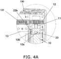
- FIG. 4A is a detail view of the P part in FIG. 3 , and shows the configuration near an origin sensor 23 in this embodiment.
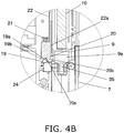
- FIG. 4B is a detail view of the Q part in FIG. 3 , and is a cross section of near the insertion opening 8 of the cartridge holder 7.
- FIG. 4C is an oblique view of the configuration near the origin sensor 23, and shows the state when the piston 10 is disposed at the origin position (an example of a reference position).
- FIGS. 3 , 4A , 4B , and 4C all show the state when the cartridge holder 7 is closed and the piston 10 is disposed at the origin position.
- the "origin position" that is an example of the reference position of the piston 10 is a position at which the piston 10 is to the rear (the upper side) of the rear end of the pharmaceutical cartridge 9 mounted to the cartridge holder 7. Specifically, when the cartridge holder 7 is opened and closed, the piston 10 is in a position where the piston 10 does not interfere with the pharmaceutical cartridge 9.
- the piston 10 is moved in and out of the pharmaceutical cartridge 9 through the insertion opening 8 in the cartridge holder 7 by a piston drive mechanism 100 composed of a feed screw 11, a gear 12, and a motor 13 (an example of a driver).
- the motor 13 is disposed so that its drive shaft is substantially parallel to the piston 10.
- a drive gear 131 that is linked to the shaft of the motor 13 is provided on the upper side of the motor 13.
- a threaded hole is formed on the inside of the piston 10, and the feed screw 11 meshes with this threaded hole.
- the rotation of the feed screw 11 moves the piston 10 up and down in FIG. 3 .
- the feed screw 11 is fixed to the gear 12 disposed above the piston 10, and the gear 12 meshes with the drive gear 131. With this configuration, the rotation of the motor 13 is transmitted through the drive gear 131 and the gear 12 to the feed screw 11, causing the feed screw 11 to rotate and drive the piston 10.
- the insertion direction in which the piston 10 is inserted into the pharmaceutical cartridge 9 mounted to the cartridge holder 7 (also referred to as downward or the forward direction) is indicated by the arrow C
- the pull-out direction in which the piston 10 is pulled out of the pharmaceutical cartridge 9 mounted to the cartridge holder 7 (also referred to as upward or the rearward direction) is indicated by the arrow D.
- the pharmaceutical injection device in this embodiment is further provided with an opening component 130 that opens the cartridge holder 7 with respect to the main case 1, an open/closed detector switch 24 that detects whether or not the cartridge holder 7 is closed, a needle detector switch 15 that detects whether or not an injection needle 16 has been mounted to the injection needle mounting component 3, and an identification component 35 that detects whether or not the pharmaceutical cartridge 9 has been mounted to the cartridge holder 7 and reads an identification label 9a affixed to the pharmaceutical cartridge 9.
- an opening component 130 that opens the cartridge holder 7 with respect to the main case 1
- an open/closed detector switch 24 that detects whether or not the cartridge holder 7 is closed
- a needle detector switch 15 that detects whether or not an injection needle 16 has been mounted to the injection needle mounting component 3
- an identification component 35 that detects whether or not the pharmaceutical cartridge 9 has been mounted to the cartridge holder 7 and reads an identification label 9a affixed to the pharmaceutical cartridge 9.
- the cartridge holder 7 will be described in detail through reference to FIGS. 1 to 4B .
- the cartridge holder 7 is tubular in shape, with the insertion opening 8 in its top face, and an opening 14 is also provided to the bottom face.
- the outer peripheral part of this opening 14 is threaded, and this becomes the injection needle mounting component 3, to which the injection needle is mounted.
- An axial support component 17 that axially supports the cartridge holder 7 so that it can open and close with respect to the main case 1 is provided to the lower outer peripheral face of the cartridge holder 7, that is, on the opening 14 side of the cartridge holder 7.
- an ejector spring 18 (an example of a biasing member) is linked to a part of the cartridge holder 7 at the opposite side (the inside) of the axial support component 17 from the direction in which the cartridge holder 7 opens.
- This ejector spring 18 is part of the opening component 130.
- the other end of the ejector spring 18 is linked to the main case 1 above.
- a holder-side linking component 71 that links to the first end 18a of the ejector spring 18 is formed on the inside portion of the end on the opening 14 side of the cartridge holder 7. Also, the ejector spring 18 is disposed along the cartridge holder 7 on the inside of the cartridge holder 7 in a closed state, and the second end 18b of the ejector spring 18 is linked to a main body-side linking component 111 formed on the main case 1 on the insertion opening 8 side.
- the cartridge holder 7 is subjected to a force in the direction in which the ejector spring 18 contracts, and the insertion opening 8 portion that is a upper portion of the cartridge holder 7 is biased in the opening direction with respect to the main case 1 as shown in FIG. 2 .
- a latched component 19 is provided as shown in FIG. 4B to the upper part of the cartridge holder 7 in order to hold the cartridge holder 7 in its closed position as shown in FIGS. 1 and 3 against the biasing in the opening direction by the ejector spring 18.
- the opening component 130 has the above-mentioned ejector spring 18, an ejector finger 20, a lever 22, and protrusions 22a and 22b.
- the ejector finger 20 is provided above the latched component 19 in the main case 1.
- the ejector finger 20 is linked adjacent to the protrusion 22a on the lower end side of the slender lever 22.
- a spring 21 is in contact with the opposite side of the protrusion 22a from the ejector finger 20, and the protrusion 22a and the ejector finger 20 are biased toward the latched component 19 below (the insertion direction C) (see FIGS. 3 and 4B ).
- the ejector finger 20 has on its inside a contact face 20a formed parallel to the movement direction of the piston 10.
- the latched component 19 has on its outside a contact face 19a formed parallel to the movement direction of the piston 10, in a state in which the cartridge holder 7 is closed. When the contact face 20a and the contact face 19a come into contact with each other, this keeps the cartridge holder 7 closed.
- the ejector finger 20 also has an inclined part 20b that is inclined outward from the lower end of the contact face 20a.
- the latched component 19 has an inclined part 19b that is inclined inward from the upper end of the contact face 19a. As discussed below, when the user closes the cartridge holder 7, the inclined part 20b slides with respect to the inclined part 19b, allowing smooth closure.
- the lever 22 has at its upper end a protrusion 22b disposed diagonally across from the protrusion 22a (at a position where the protrusion direction is reversed), and the protrusion 22b is provided on the feed screw 11 side of the piston 10.
- the slender lever 22 is disposed along the movement direction of the piston 10, along the inside of the piston 10 when it has not yet been inserted into the pharmaceutical cartridge 9.
- the protrusion 22a and the ejector finger 20 are provided on the cartridge holder 7 side of the lever 22, and the protrusion 22b is provided on the gear 12 side of the lever 22.
- the lever 22 links the protrusion 22b and the ejector finger 20, and the lever 22, the protrusion 22b, and the ejector finger 20 are biased downward by the spring 21 so as to latch the latched component 19.
- the origin sensor 23 which senses the origin position of the piston 10, is provided on the rear end side of the piston 10 (the upper end side (the pull-out direction D side) in FIG. 1 ). This origin sensor 23 is fixed on the inside of the main case 1.
- the origin sensor 23 can be a transmission type of photoelectric sensor, for example.
- a detection signal is sent to a controller 25 (discussed below), and the piston position at this point (the piston position shown in FIG. 4C ) is termed the origin position (an example of a reference position) of the piston 10.
- a protrusion 10b that protrudes to the lever 22 side is provided to the piston 10.
- This protrusion 10b is formed at a position where it hits the protrusion 22b of the lever 22 only when the piston 10 retracts upward from the origin position (moves in the pull-out direction D), on the insertion direction C side of the protrusion 22b.
- the protrusion 10b hits the protrusion 22b and retracts the protrusion 22b, the entire lever 22 is retracted along with the protrusion 22b(moved upward in FIGS. 1 and 2 ).
- FIG. 5 shows the internal configuration of the pharmaceutical injection device in this embodiment.
- FIG. 6A shows the configuration near the origin sensor 23 in this embodiment.
- FIG. 6B is a cross section of near the insertion opening 8 of the cartridge holder 7, and is a detail view of the S part of FIG. 5 .
- FIG. 6C is an oblique view of the configuration near the origin sensor 23.
- FIGS. 5 , 6A , 6B , and 6C all show the state when the piston 10 is moved in the insertion direction C in order to inject a pharmaceutical.
- the latched component 19 provided inside the main case 1 engages with the ejector finger 20 that is adjacent to the protrusion 22a on the lower end side of the lever 22, which keeps the cartridge holder 7 closed.
- the ejector finger 20 and the lever 22 are separate members that are linked together, but this is not the only option, and they may be formed integrally instead.
- the pharmaceutical injection device in this embodiment is provided with a open/closed detector switch 24 that detects that the cartridge holder 7 has been closed.
- the open/closed detector switch 24 is a push-type detector switch, for example, and as shown in FIGS. 3 and 4B , it is disposed near the upper end of the cartridge holder 7.
- the side face 7a of the cartridge holder 7 pushes the open/closed detector switch 24 to its on state, and it is detected that the cartridge holder 7 has been closed.
- the injection needle mounting component 3 is provided with the needle detector switch 15, and as shown in FIG. 5 , this needle detector switch 15 detects whether or not the injection needle 16 has been mounted to the injection needle mounting component 3.
- FIG. 7a shows the configuration near the injection needle mounting component 3 in a state in which the injection needle 16 has not been mounted.
- the needle detector switch 15 is disposed near the injection needle mounting component 3.
- the needle detector switch 15 has a rotary part 150 and a detecting part 151.
- the rotary part 150 is able to rotate around a rotary shaft 150a, and is biased downward by a spring member or the like (not shown).
- the detecting part 151 is switched on by upward rotation of the rotary part 150 (see the arrow E), and thereby detects the mounting of the injection needle 16 to the injection needle mounting component 3.
- FIG. 7b shows the configuration of the injection needle 16.
- the injection needle 16 has a cap 160 for mounting to the injection needle mounting component 3.
- This cap 160 is cylindrical in shape, and is threaded on its inside. The outside of the injection needle mounting component 3 is also threaded, and the injection needle 16 is mounted to the injection needle mounting component 3 by meshing these threads with the threads of the cap 160.
- FIG. 7c shows the configuration near the injection needle mounting component 3 in a state in which the injection needle 16 has been mounted.
- the rotary part 150 is pushed up by the cap 160 and rotates upward around the rotary shaft 150a. This rotation switches on the detecting part 151, and it is thereby detected that the injection needle 16 has been mounted.
- the identification component 35 is provided to the main case 1 of the pharmaceutical injection device in this embodiment. This identification component 35 detects whether or not the pharmaceutical cartridge 9 has been mounted to the cartridge holder 7, and also reads the identification label 9a (see FIG. 2 ) affixed to the pharmaceutical cartridge 9. The identification component 35 is provided at a position opposite the identification label 9a of the pharmaceutical cartridge 9 mounted to the cartridge holder 7.
- the identification label 9a is a label (colored marker) applied to the pharmaceutical cartridge 9, and is used to identify the pharmaceutical contained in the pharmaceutical cartridge 9.
- the identification component 35 first detects whether or not there is a pharmaceutical cartridge 9. If the presence of a pharmaceutical cartridge 9 is detected, the identification label 9a affixed to that pharmaceutical cartridge 9 is read, and it is detected whether or not the correct pharmaceutical cartridge 9 has been mounted.
- the identification component 35 is configured to include a color sensor, a photosensor, or the like for detecting the presence of a pharmaceutical cartridge 9 and reading the identification label 9a.
- the color sensor may be a monochrome (such as red or blue) color sensor, or an RGB color sensor for sensing a plurality of colors.
- the identification component 35 outputs the detection result for the pharmaceutical cartridge 9 and information read from the identification label 9a to the controller 25.
- a label written in colored marker is given as an example of the identification label 9a, but this is not the only option, and a color may be applied directly to the pharmaceutical cartridge 9, for instance.
- the identification label 9a may be a barcode (one- or two-dimensional).
- the identification component 35 is constituted by a BCR (a one- or two-dimensional barcode reader).
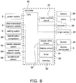
- FIG. 8 is a block diagram of the electrical circuitry in the main case 1 of the pharmaceutical injection device of the present invention, as well as its surroundings.
- the controller 25 has a CPU 250, is connected to various I/O interfaces or drive systems, and performs control over these.
- the CPU 250 of the controller 25 is connected to the power switch 2, the pharmaceutical injection switch 4, the setting switch 6, and other such input components, and checks the input of various control switches.
- the needle detector switch 15 that detects whether an injection needle has been mounted
- the open/closed detector switch 24 that detects whether the cartridge holder 7 is open or closed
- an acceleration sensor 34 that detects whether the cartridge holder 7 is open or closed
- the identification component 35 are connected to the CPU 250 of the controller 25.
- the motor 13 that drives the piston 10 is connected to the CPU 250 via a motor control circuit 27 inside the controller 25.
- an encoder 28 that senses information about the position of the piston 10 is connected to the motor 13, and pulses corresponding to the rotation of the motor 13 are outputted to the CPU 250.
- the CPU 250 counts the pulses outputted by the encoder 28 to calculate the amount of movement of the piston 10.
- the CPU 250 is also connected to the origin sensor 23 that senses the origin position of the piston 10, and the CPU 250 uses the output of the encoder 28 and the output of the origin sensor 23 to recognize the current piston position.
- the CPU 250 is connected to a memory 32, and the recognized current piston position is stored as piston position information.
- the piston position information is a positive or negative numerical value, and when the piston position information is zero, it means that the piston is in the origin position. When the piston position information is positive, it means that the piston is below the origin position. Conversely, when the piston position information is negative, it means that the piston is above the origin position.
- the absolute value of the piston position information refers to the movement distance from the origin position.
- the CPU 250 resets the piston position information stored in the memory 32 to zero (meaning that the piston is in the origin position) when the rear end side of the protrusion 10a provided to the piston 10 has crossed the origin sensor 23.
- the CPU 250 updates the value every time the encoder 28 connected to the motor 13 outputs a pulse, by adding or subtracting one to or from the piston position information according to the drive direction of the motor 13. In this way, the CPU 250 uses the piston position information stored in the memory 32 to recognize the current piston position.
- the memory 32 here is constituted by an EEPROM or another such nonvolatile memory, and the piston position information stored in the memory 32 is maintained even when the power to the device is shut off.
- This piston position information is reset to zero every time the rear end side of the protrusion 10a provided to the piston 10 crosses the origin sensor 23. That is, the origin sensor 23 is used to correct the piston position.
- the CPU 250 monitors the output of the origin sensor 23, and if the error with respect to zero in the piston position information stored in the memory 32 when the origin sensor 23 senses the origin position exceeds a specific threshold, there is the possibility that some kind of error will occur in the operation of the device, so processing is performed to display a warning on the display component 5 and stop the operation, for example.
- a buzzer 30 that notifies the user when an error has occurred is connected within the controller 25 to the CPU 250 via a buzzer drive circuit 29 that controls the buzzer 30.
- the memory 32 which stores dose amounts, administration data, and so forth, and a timer 33, which measures elapsed time, are installed in the controller 25 and connected to the CPU 250.
- a battery is also installed as the power supply for the device, and is connected to the controller 25.
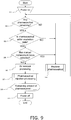
- FIG. 9 is a flowchart showing an overview of the operation of the pharmaceutical injection device in this embodiment.
- the controller 25 checks the remaining amount of pharmaceutical (S2), and confirms whether or not the pharmaceutical is within its expiration date (S3). More precisely, the controller 25 records the date and time the pharmaceutical cartridge was last replaced, the number of pharmaceutical injections, the pharmaceutical injection amount, and so forth in the memory 32, and makes a determination on the basis of what is recorded. If there is not enough pharmaceutical, or if the pharmaceutical has passed its expiration date, the control proceeds to S4, and processing is performed for the replacement of the pharmaceutical cartridge 9. At this point a message prompting the user to replace the pharmaceutical may be displayed on the display component 5.
- Air removal processing is the performed (S6).
- FIG. 10 is a flowchart of the operation involved in this air removal processing.
- the controller 25 uses the needle detector switch 15 to check whether or not the injection needle 16 has been mounted to the injection needle mounting component 3 (S41). If it is detected that the injection needle 16 has not been mounted, the controller 25 displays "Attach injection needle" on the display component 5 (S42).
- the controller 25 displays "Remove air. Press pharmaceutical injection switch" on the display component 5 (S43).
- the user is prompted by the display in S43 to press the pharmaceutical injection switch (S44).
- the controller 25 drives the motor 13, the gear 12 meshed with the drive gear 131 of the motor 13 rotates, and this rotation of the gear 12 rotates the feed screw 11, and the rotation is converted into linear motion of the piston 10 (S45).
- the controller 25 senses the amount of movement of the piston from the output of the encoder 28, and moves the piston forward by a distance equivalent to a specific amount of air removal (S46).
- the controller 25 stops the motor 13 and ends the air removal operation (S47).
- the controller 25 displays "If finished, press middle switch. Press left switch to remove air again" on the display component 5 (S48). The user at this point visually confirms the air removal state, and selects whether to end the air removal operation or to perform the air removal operation again.
- the actuation of the air removal operation is also handled by the pharmaceutical injection switch 4, but if an air removal switch (not shown) is provided separately, this air removal switch is used instead. That is, in S44, the motor 13 may be started (S45) by pressing the air removal switch.
- FIG. 11 is a flowchart of the operation in pharmaceutical injection processing. This pharmaceutical injection processing will be described through reference to FIGS. 5 , 6A , 6B , and 6C .
- the above-mentioned FIGS. 3 , 4A , 4B , and 4C show the initial state of the pharmaceutical injection device of the present invention, but FIGS. 5 , 6A , 6B , and 6C show the operation of injecting the pharmaceutical (at the start of the injection operation).
- the state shown in FIGS. 5 , 6A , 6B , and 6C is also the same at the start of the air removal operation discussed above.
- the controller 25 displays "Inject. Insert needle and press pharmaceutical injection switch to inject pharmaceutical" on the display component 5 (S61). This prompts the user to insert the needle and press the pharmaceutical injection switch 4. The injection of the pharmaceutical contained in the pharmaceutical cartridge is commenced by pressing the pharmaceutical injection switch 4 (see FIG. 2 ) provided to the outer peripheral surface of the main case 1.
- the controller 25 senses the amount of movement of the piston from the output of the encoder 28, and moves the piston 10 in the insertion direction C by a distance equivalent to a specific amount of pharmaceutical injection (S65).
- controller 25 stops the motor 13 after the piston 10 has advanced by a specific amount (S66).
- the controller 25 then displays "Leave needle inserted for a moment before removing" on the display component 5 so that the user will keep the needle in its inserted state, without removing it, until all of the pharmaceutical has completely stopped coming out of the needle, even after the drive motor 15 has stopped (S67).
- the controller 25 After waiting (S68) for a specific length of time (such as 10 seconds) to elapse after the start of the display in S67, the controller 25 causes the display component 5 to display "Pull out needle” (S69). This prompts the user to remove the injection needle 16.
- the user removes the injection needle 16 in response to the display on the display component 5 (S70).
- the controller 25 ends the pharmaceutical injection processing (S71). If the injection needle 16 has not been removed, the controller 25 causes the display component 5 to display "Remove injection needle” (S72).
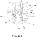
- FIG. 12 is a cross section of the pharmaceutical injection device when the cartridge holder 7 has been opened.
- FIG. 13A shows the configuration near the origin sensor 23, and is a detail view of the T part in FIG. 12 .
- FIG. 13B is a cross section of near the insertion opening 8 of the cartridge holder 7, and is a detail view of the U part in FIG. 12 .
- FIG. 13C is an oblique view of the configuration near the origin sensor 23.
- the ejector finger 20 attached to the lower end of the lever 22 also moves upward together while compressing the biasing spring 21, and this operation disengages the ejector finger 20 and the latched component 19. That is, the contact face 20a of the ejector finger 20 slides in the pull-out direction D, and thereby moves away from the contact face 19a of the latched component 19.
- the cartridge holder 7 at this point is opened outward from the main case 1 (see the arrow A in FIG. 12 ) by the biasing force of the ejector spring 18, with the axial support component 17 serving as the fulcrum.
- Whether or not the cartridge holder 7 has been opened here can be detected by the open/closed detector switch 24 provided near the ejector finger 20 (see FIG. 4B , etc.).
- the injection needle 16 mounted to the injection needle mounting component 3 must be removed for the sake of safety, so the display component 5 provided to the front of the main case 1 gives a display prompting the user to remove the injection needle 16.
- the removal of the injection needle 16 can be detected by the needle detector switch 15 shown in FIG. 7 .
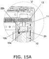
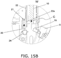
- FIG. 14 is a cross section of the pharmaceutical injection device in a state in which the piston 10 has returned to its origin position while the cartridge holder 7 is open.
- FIG. 15A shows the configuration near the origin sensor 23, and is a detail view of the V part in FIG. 14 .
- FIG. 15B is a cross section of near the insertion opening 8 of the cartridge holder 7, and is a detail view of the W part in FIG. 14 .
- FIG. 15C is an oblique view of the configuration near the origin sensor 23.
- FIGS. 14 , 15A , 15B , and 15C show a state in which the piston 10 has been moved in the insertion direction C to its origin position after the eject operation illustrated in FIGS. 12 , 13A , 13B , and 13C .
- the pharmaceutical cartridge 9 is replaced, and the cartridge holder 7 is moved toward the main case 1 to close it, whereupon the inclined part 19b of the latched component 19 moves while riding up onto the inclined part 20b of the ejector finger 20, and finally the latched component 19 engages with the ejector finger 20 and is held in that state.
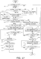
- FIG. 16 is premised on the timing at which it becomes necessary to eject (open) the cartridge holder 7.
- Examples of the timing of this ejection (opening) include a case in which the pharmaceutical in the pharmaceutical cartridge 9 has been completely injected as shown in FIG. 9 (S2), a case in which it becomes necessary to replace the pharmaceutical after a specific length of time has elapsed (S3), and a case in which manual replacement has been selected (S4).
- a case in which it becomes necessary to replace the pharmaceutical after a specific length of time has elapsed is, for example, one in which more than a specific time period (five weeks in this case) has elapsed since the pharmaceutical cartridge 9 was installed in the pharmaceutical injection device, when the expiration period has been determined to be five weeks after the start of usage.
- timer 33 is started when the pharmaceutical cartridge 9 is replaced, and the time on the timer 33 indicates that a specific length of time has elapsed, control is performed so that the pharmaceutical cartridge will be replaced, as an expiration error.
- Examples of when the timer 33 is started here include when the pharmaceutical cartridge 9 is replaced and the timer is started at the point when the open/closed detector switch 24 detects that the cartridge holder 7 has been closed, and when the timer is started at the point when the pharmaceutical in the pharmaceutical cartridge 9 was first injected (start of pharmaceutical administration).
- the conditions that require the replacement of the pharmaceutical cartridge 9 include when there is no pharmaceutical in the pharmaceutical cartridge 9, when the pharmaceutical is past its expiration date, and when replacement has been selected from the menu.
- the controller 25 uses the open/closed detector switch 24 to detect whether or not the cartridge holder 7 is closed, as shown in FIG. 16 (S11).
- the controller 25 displays on the LCD panel (the display component 5) a message prompting the user to replace the pharmaceutical cartridge 9 and close the cartridge holder 7 (displayed as "Door” on the display component 5) (S21).
- the controller 25 confirms whether or not the piston 10 is near the origin position by referring to the piston position information stored in the memory 32 (S12).
- the controller 25 determines that the piston 10 is near the origin position if the piston position information is zero or within a specific range of positive or negative offset.
- the controller 25 actuates the motor control circuit 27, rotates the motor 13, and moves the piston 10 back (in the pull-out direction D) (S24).
- the controller 25 uses the needle detector switch 15 to confirm whether or not the injection needle 16 is mounted (S13). If the injection needle 16 is still mounted, the controller 25 displays on the display component 5 a message prompting the user to remove the injection needle 16 (S25).
- the controller 25 uses the acceleration sensor 34 to check whether or not the injection needle mounting component 3 is facing in the gravity direction (S14). If the injection needle mounting component 3 is not facing in the gravity direction, the controller 25 displays "Point injection needle mounting component downward" on the display component 5 (S26). This is because if the opening side of the cartridge holder 7 (the opposite side from the axial support component 17) is facing downward (in the gravity direction), there is the risk that the pharmaceutical cartridge 9 will fall out and be damaged when the cartridge holder 7 is opened.
- the orientation of the device is sensed by the acceleration sensor 34, and if the opening side of the cartridge holder 7 is facing downward, a warning prompting the user to change the orientation of the device is displayed on the display component 5.
- the device need not be strictly facing in the gravity direction, and it may be considered to be facing in the gravity direction if it is closer to the gravity direction than to the horizontal direction, for example.
- the controller 25 displays on the display component 5 a message telling the user to open the cartridge holder 7 (S15). The rotation of the motor 13 has been stopped at this point.
- controller 25 commands the motor control circuit 27 to rotate the motor 13 and move the piston 10 further back (pull-out direction D) from the origin position.
- this causes the protrusion 10b of the piston 10 and the protrusion 22b of the lever 22 to come into contact, and the entire slender lever 22 moves upward.
- the ejector finger 20 attached adjacent to the lower side of the lever 22 also retracts upward, moving away and disengaging from the latched component 19 provided to the cartridge holder 7.
- the controller 25 uses the open/closed detector switch 24 to check whether or not the cartridge holder 7 has opened (S17).
- the controller 25 determines whether or not the current position of the piston 10, found from the output of the encoder 28 connected to the motor 13, has reached a preset limit position (a position at which the piston 10 has retracted far enough from the origin position for the latched component 19 and the ejector finger 20 to separate) (S27).
- the controller 25 again moves the piston 10 in the insertion direction C to its origin position via the motor control circuit 27, the motor 13, the gear 12, the feed screw 11, etc. (S18).
- the controller 25 uses the piston position information to confirm whether or not the piston 10 has returned to its origin position (S 19), and if it has not returned to the origin position, the operation to advance the piston 10 is continued.
- the controller 25 stops the motor 13 via the motor control circuit 27, and stops the piston 10 (S20).
- the controller 25 displays on the display component 5 a message prompting the user to close the cartridge holder 7 after replacement of the pharmaceutical cartridge 9 (S21).
- the pharmaceutical cartridge 9 is then replaced, and the open/closed detector switch 24 detects whether or not the cartridge holder 7 has been closed (S22).
- the controller 25 performs pharmaceutical identification processing (S23).
- the controller 25 uses the identification component 35 to read the identification label 9a affixed to the pharmaceutical cartridge 9, and confirms whether or not the proper pharmaceutical cartridge 9 has been mounted to the cartridge holder 7. If it is determined that an improper pharmaceutical cartridge 9 has been mounted to the cartridge holder 7, the controller 25 gives an error display on the display component 5, and performs control to open the cartridge holder 7. On the other hand, if the controller 25 determines that the proper pharmaceutical cartridge 9 has been mounted to the cartridge holder 7, pharmaceutical replacement processing is ended.
- the timer 33 (see FIG. 11 ) may be started at this point.
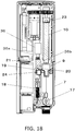
- FIG. 18 is a front cross section of the internal configuration of the pharmaceutical injection device, and shows a modification of what is shown in FIG. 3 .
- the pharmaceutical injection device shown in FIG. 18 differs from the pharmaceutical injection device shown in FIG. 3 in that a solenoid 36 is provided, and that a linking component 36b is provided instead of the lever 22.
- the linking component 36b links the ejector finger 20 to a movable core 36a, which is an element of the solenoid 36.
- the movable core 36a is linked to the linking component 36b through the inside of the spring 21.
- One end of the spring 21 touches the main case 1, the other end touches the linking component 36b, and the spring 21 is disposed so as to bias the linking component 36b downward.
- the action of the solenoid 36 causes the ejector finger 20 linked to the linking component 36b to move up or down.
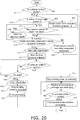
- FIG. 19 is a block diagram of the control configuration of the pharmaceutical injection device, and shows a modification of what is shown in FIG. 8 .
- the block diagram in FIG. 19 differs from the block diagram in FIG. 8 in that the controller 25 has a solenoid drive circuit 37 for driving the solenoid 36, and this solenoid drive circuit 37 is connected to the CPU 250.
- the controller 25 uses the open/closed detector switch 24 to detect whether or not the cartridge holder 7 is closed (S11).
- the controller 25 refers to the piston position information stored in the memory 32 to determine whether or not the piston 10 is near the origin position (S12).
- the controller 25 determines that the piston 10 is near the origin position if the piston position information is zero or within a specific range of positive or negative offset.
- the controller 25 actuates the motor control circuit 27, rotates the motor 13, and moves the piston 10 back (in the pull-out direction D) (S24).
- the controller 25 uses the needle detector switch 15 to confirm whether or not the injection needle 16 is mounted (S13). If the injection needle 16 is still mounted, the controller 25 displays on the display component 5 a message prompting the user to remove the injection needle 16 (S25).
- the controller 25 uses the acceleration sensor 34 to check whether or not the injection needle mounting component 3 is facing in the gravity direction (S14). If the injection needle mounting component 3 is not facing in the gravity direction, the controller 25 displays "Point injection needle mounting component downward" on the display component 5 (S26). This is because if the opening side of the cartridge holder 7 (the opposite side from the axial support component 17) is facing downward (in the gravity direction), there is the risk that the pharmaceutical cartridge 9 will fall out and be damaged when the cartridge holder 7 is opened.
- the orientation of the device is sensed by the acceleration sensor 34, and if the opening side of the cartridge holder 7 is facing downward, a warning prompting the user to change the orientation of the device is displayed on the display component 5.
- the device need not be strictly facing in the gravity direction, and it may be considered to be facing in the gravity direction if it is closer to the gravity direction than to the horizontal direction, for example.
- the controller 25 displays on the display component 5 a message telling the user to open the cartridge holder 7 (S15). The rotation of the motor 13 has been stopped at this point.
- the controller 25 commands the solenoid drive circuit 37 to start sending power to the solenoid 36 (S31).
- S31 When power is sent to an internal coil (not shown) in the solenoid 36, an attractive force is generated between the movable core 36a and a stationary core (not shown) in the solenoid 36, and the movable core 36a pulls the linking component 36b up.
- the ejector finger 20 attached adjacent to the lower side of the linking component 36b also moves upward and away from the latched component 19 provided to the cartridge holder 7, which releases their engagement.
- the controller 25 uses the open/closed detector switch 24 to determine whether or not the cartridge holder 7 has opened (S17).
- the controller 25 uses the timer 33 to determine whether or not the elapsed time since the start of operation of the solenoid 36 has exceeded a timeout time (S32).
- the controller 25 shuts off the power to the solenoid 36 (S34).
- the solenoid 36 When power to the internal coil of the solenoid 36 is shut off, the attractive force of the stationary core and the movable core 36a is eliminated, and the spring 21 returns the movable core 36a, the linking component 36b, and the ejector finger 20 to their initial positions (the position where the ejector finger 20 can be engaged with the latched component 19 of the cartridge holder 7).
- the controller 25 causes the display component 5 to display a message prompting the user to close the cartridge holder 7 after replacing the pharmaceutical cartridge 9 (S21).
- the pharmaceutical cartridge 9 is then replaced, and the open/closed detector switch 24 detects whether or not the cartridge holder 7 has been closed (S22).
- the controller 25 performs pharmaceutical identification processing (S23).
- the controller 25 uses the identification component 35 to read the identification label 9a affixed to the pharmaceutical cartridge 9, and confirms whether or not the proper pharmaceutical cartridge 9 has been mounted to the cartridge holder 7. If it is determined that an improper pharmaceutical cartridge 9 has been mounted to the cartridge holder 7, the controller 25 gives an error display on the display component 5, and performs control to open the cartridge holder 7. On the other hand, if the controller 25 determines that the proper pharmaceutical cartridge 9 has been mounted to the cartridge holder 7, pharmaceutical replacement processing is ended.
- the timer 33 (see FIG. 11 ) may be started at this point.
- the pharmaceutical injection device of the present invention allows a cartridge holder to be openly easily, and is expected to find use as a pharmaceutical injection device for injecting insulin, growth hormone, or another such pharmaceutical, for example.
Landscapes
- Health & Medical Sciences (AREA)
- Vascular Medicine (AREA)
- Engineering & Computer Science (AREA)
- Anesthesiology (AREA)
- Biomedical Technology (AREA)
- Heart & Thoracic Surgery (AREA)
- Hematology (AREA)
- Life Sciences & Earth Sciences (AREA)
- Animal Behavior & Ethology (AREA)
- General Health & Medical Sciences (AREA)
- Public Health (AREA)
- Veterinary Medicine (AREA)
- Infusion, Injection, And Reservoir Apparatuses (AREA)
Claims (15)
- Arzneimittel-Injektionsvorrichtung, mit:einem Kartuschen-Halter, an dem eine Arzneimittel-Kartusche angebracht ist,einem Hauptgehäuse, an dem der Kartuschen-Halter in zu öffnender Weise und zu schließender Weise vorgesehen ist,einem Kolben, der in die Arzneimittel-Kartusche, die an dem Kartuschen-Halter angebracht ist, eingeführt werden kann,und gekennzeichnet dadurch, dass sie ferner aufweist:einen Antrieb, der den Kolben in entweder einer Einführrichtung, in der der Kolben in die Arzneimittel-Kartusche eingeführt wird, oder einer Auszugsrichtung bewegt, in der der Kolben aus der Arzneimittel-Kartusche herausgezogen wird,einer Öffnungskomponente, die den Kartuschen-Halter in Zusammenarbeit mit der Bewegung des Kolbens in der Auszugsrichtung öffnet,einem Kartuschen-Halter-Detektor, der erfasst, ob der Kartuschen-Halter geöffnet oder geschlossen ist, undeiner Steuereinheit, die den Antrieb steuert, so dass der Kolben gestoppt wird, wenn der Kartuschen-Halter-Detektor erfasst hat, dass der Kartuschen-Halter geöffnet ist.
- Arzneimittel-Injektionsvorrichtung nach Anspruch 1,
wobei eine Referenzposition, an der der Kartuschen-Halter in seinem geschlossenen Zustand gehalten werden kann, als eine Position vorgesehen ist, zu der sich der Kolben bewegt, wenn er nicht in die Arzneimittel-Kartusche eingeführt ist, und
die Öffnungskomponente den Kartuschen-Halter in Zusammenarbeit mit der Bewegung des Kolbens von der Referenzposition in der Auszugsrichtung öffnet. - Arzneimittel-Injektionsvorrichtung nach Anspruch 2,
wobei die Öffnungskomponente aufweist:eine kontaktierte Komponente, die durch eine kontaktierende Komponente getroffen wird, die an dem Kolben gebildet ist, und sich in der Auszugsrichtung zusammen mit der Bewegung des Kolbens bewegt, wenn der Kolben sich von der Referenzposition in die Auszugsrichtung bewegt,eine Verriegelungskomponente, die eine verriegelte Komponente, die an dem Kartuschen-Halter gebildet ist, verriegelt,eine Verbindungskomponente, die die kontaktierte Komponente und die verriegelnde Komponente verbindet, undein erstes Vorspannelement, das den Kartuschen-Halter in seiner Öffnungsrichtung vorspannt, unddie Verriegelungskomponente über die Verbindungskomponente mit einer Bewegung der verriegelten Komponente in der Auszugsrichtung zusammenarbeitet, was die Verriegelung der verriegelten Komponente durch die verriegelnde Komponente freigibt, und der Kartuschen-Halter durch die Vorspannungskraft des ersten Vorspannungselements geöffnet wird. - Arzneimittel-Injektionsvorrichtung nach Anspruch 3,
wobei die verriegelte Komponente, die Verbindungskomponente und die verriegelnde Komponente entlang der Bewegungsrichtung des Kolbens angeordnet sind,
die Vorrichtung ferner ein zweites Vorspannungselement aufweist, das die verriegelte Komponente, die Verbindungskomponente und die verriegelnde Komponente in der Einführrichtung vorspannt,
das zweite Vorspannelement die verriegelnde Komponente vorspannt, so dass es die verriegelte Komponente verriegelt, und
eine Bewegung des Kolbens von der Referenzposition in der Auszugsrichtung die verriegelte Komponente, die Verbindungskomponente und die verriegelnde Komponente veranlasst, sich entgegen der Vorspannkraft des zweiten Vorspannelements zu bewegen, und die Verriegelung der verriegelten Komponente durch die verriegelnde Komponente freigibt. - Arzneimittel-Injektionsvorrichtung nach Anspruch 2, mit:einem Referenzpositionssensor, der erfasst, dass der Kolben an der Referenzposition angeordnet ist, undeiner Zeitmesskomponente, die eine abgelaufene Zeit misst,wobei die Steuereinheit eine Steuerung zum Betreiben des Antriebs durchführt, um so den Kolben von dem Referenzpositionssensor in der Auszugsrichtung zu bewegen, wonach der Betrieb des Antriebs gestoppt wird, wenn die Öffnung des Kartuschen-Halters nicht erfasst wird, auch wenn eine bestimmte Zeit abgelaufen ist.
- Arzneimittel-Injektionsvorrichtung nach Anspruch 2 mit:einem Referenzpositionssensor, der erfasst, dass sich der Kolben an der Referenzposition befindet,einer Anzeigekomponente, die an dem Hauptgehäuse vorgesehen ist, undeiner Zeitmesskomponente, die eine abgelaufene Zeit misst,wobei die Steuereinheit eine Steuerung zum Betrieb des Antriebs durchführt, um so den Kolben von dem Referenzpositionssensor in der Auszugsrichtung zu bewegen, wonach eine Anzeige, die einen Fehler angibt, in der Anzeigekomponente angezeigt wird, wenn die Öffnung des Kartuschen-Halters nicht erfasst wird, auch wenn eine bestimmte Zeit abgelaufen ist.
- Arzneimittel-Injektionsvorrichtung nach Anspruch 2, mit:einem Referenzpositionssensor, der erfasst, dass sich der Kolben an der Referenzposition befindet, undeinem Bewegungsausmaßsensor, der ein Ausmaß von Bewegung des Kolbens auf Basis einer Ausgabe eines Motors erfasst, der an dem Antrieb vorgesehen ist,wobei die Steuereinheit eine Steuerung zum Betreiben des Antriebs durchführt, um so den Kolben von dem Referenzpositionssensor in der Auszugsrichtung zu bewegen, wonach der Betrieb des Antriebs gestoppt wird, wenn die Öffnung des Kartuschen-Halters nicht erfasst wird, auch wenn das Ausmaß einer Bewegung des Kolbens, das durch den Bewegungsausmaßsensor erfasst wird, ein bestimmtes Bewegungsausmaß erreicht hat.
- Arzneimittel-Injektionsvorrichtung nach Anspruch 2, mit:einem Referenzpositionssensor, der erfasst, dass sich der Kolben an der Referenzposition befindet, undeinem Bewegungsausmaßsensor, der ein Bewegungsausmaß des Kolbens auf Basis der Ausgabe eines Motors erfasst, der an dem Antrieb vorgesehen ist,wobei die Steuereinheit den Antrieb derart betreibt, dass der Kolben von dem Referenzpositionssensor in der Auszugsrichtung bewegt wird, wonach eine Anzeige, die einen Fehler angibt, auf der Anzeigekomponente angezeigt wird, wenn die Öffnung des Kartuschen-Halters nicht erfasst wird, auch wenn das Bewegungsausmaß des Kolbens, das durch den Bewegungsausmaßsensor erfasst wird, ein bestimmtes Bewegungsausmaß erreicht hat.
- Arzneimittel-Injektionsvorrichtung nach Anspruch 1,
mit einer Zeitmesskomponente, die eine abgelaufene Zeit misst, seitdem die Arzneimittel-Kartusche an dem Kartuschen-Halter angebracht wurde,
wobei die Steuereinheit den Kolben in der Auszugsrichtung bewegt, um die Öffnungskomponente zu betreiben, wenn die abgelaufene Zeit eine bestimmte Zeitdauer erreicht hat. - Arzneimittel-Injektionsvorrichtung nach einem der Ansprüche 1 bis 9,
mit einer Anzeigekomponente, die an dem Hauptgehäuse vorgesehen ist,
wobei die Steuereinheit eine Anzeige auf der Anzeigekomponente anzeigt, um das Öffnen des Kartuschen-Halters anzugeben, bevor der Kartuschen-Halter geöffnet wird. - Arzneimittel-Injektionsvorrichtung nach einem der Ansprüche 1 bis 9,
mit einer Anzeigekomponente, die an dem Hauptgehäuse vorgesehen ist,
wobei die Steuereinheit auf der Anzeigekomponente eine Anzeige angibt, die einen Benutzer auffordert, die Arzneimittel-Kartusche auszutauschen, wenn die Öffnung des Kartuschen-Halters durch den Kartuschen-Halter-Detektor erfasst wird. - Arzneimittel-Injektionsvorrichtung nach Anspruch 11,
wobei die Steuereinheit auf der Anzeigekomponente eine Anzeige anzeigt, die einen Benutzer auffordert, die Arzneimittel-Kartusche auszutauschen und dann den Kartuschen-Halter zu schließen, wenn das Öffnen des Kartuschen-Halters durch den Kartuschen-Halter-Detektor erfasst wird. - Arzneimittel-Injektionsvorrichtung nach einem der Ansprüche 1 bis 9, mit:einer Injektionsnadelanbringkomponente zum Anbringen einer Injektionsnadel, die ein Arzneimittel in der Arzneimittel-Kartusche in einen Körper injiziert,einem Injektionsnadeldetektor, der das Anbringen der Injektionsnadel an der Injektionsnadelanbringkomponente erfasst, undeiner Anzeigekomponente, die an dem Hauptgehäuse vorgesehen ist,wobei die Steuereinheit auf der Anzeigekomponente einer Anzeige anzeigt, die den Benutzer auffordert, die Injektionsnadel zu entfernen, vor dem Öffnen des Kartuschen-Halters, wenn der Injektionsnadeldetektor das Anbringen der Injektionsnadel erfasst hat.
- Arzneimittel-Injektionsvorrichtung nach Anspruch 3,
wobei der Kartuschen-Halter röhrenförmig in seiner Form ist, mit einer Einführöffnung, in die die Arzneimittel-Kartusche eingeführt ist, die an dem Ende auf der Auszugsrichtungsseite vorgesehen ist, und aufweist:eine axiale Tragekomponente, die auf einer äußeren Fläche des Hauptgehäuses am Ende des Kartuschen-Halters auf der Einführrichtungsseite vorgesehen ist und den Kartuschen-Halter rotierbar an dem Hauptgehäuse trägt, undeiner halterseitigen Verbindungskomponente, die gegenüber der axialen Tragekomponente an dem Ende des Kartuschen-Halters auf der Einführrichtungsseite vorgesehen ist, und mit der ein erstes Ende des ersten Vorspannelements verbunden ist,wobei das Hauptgehäuse ein hauptkörperseitiges Verbindungselement aufweist, mit dem ein zweites Ende des ersten Vorspannelements verbunden ist, das entlang dem Kartuschen-Halter angeordnet ist, unddas erste Vorspannelement derart vorspannt, dass die halterseitige Verbindungskomponente zu der hauptkörperseitigen Verbindungskomponente gezogen wird. - Arzneimittel-Injektionsvorrichtung nach Anspruch 11 oder 12,
mit einem Leser, der eine Identifikationskomponente liest, die an derm Arzneimittel-Kartusche vorgesehen ist,
wobei, wenn der Kartuschen-Halter-Detektor erfasst, dass der Kartuschen-Halter nach der Anzeige geschlossen wurde, die Steuereinheit den Leser verwendet, um die Identifikationskomponente zu lesen, und bestimmt, ob eine richtige Arzneimittel-Kartusche angebracht wurde.
Priority Applications (1)
| Application Number | Priority Date | Filing Date | Title |
|---|---|---|---|
| EP16204229.5A EP3178505B1 (de) | 2012-12-13 | 2013-12-13 | Medikamenteninjektionsvorrichtung |
Applications Claiming Priority (2)
| Application Number | Priority Date | Filing Date | Title |
|---|---|---|---|
| JP2012271961 | 2012-12-13 | ||
| PCT/JP2013/007351 WO2014091765A1 (ja) | 2012-12-13 | 2013-12-13 | 薬剤注入装置 |
Related Child Applications (2)
| Application Number | Title | Priority Date | Filing Date |
|---|---|---|---|
| EP16204229.5A Division EP3178505B1 (de) | 2012-12-13 | 2013-12-13 | Medikamenteninjektionsvorrichtung |
| EP16204229.5A Division-Into EP3178505B1 (de) | 2012-12-13 | 2013-12-13 | Medikamenteninjektionsvorrichtung |
Publications (3)
| Publication Number | Publication Date |
|---|---|
| EP2932993A1 EP2932993A1 (de) | 2015-10-21 |
| EP2932993A4 EP2932993A4 (de) | 2016-01-06 |
| EP2932993B1 true EP2932993B1 (de) | 2017-03-29 |
Family
ID=50934071
Family Applications (2)
| Application Number | Title | Priority Date | Filing Date |
|---|---|---|---|
| EP13862901.9A Active EP2932993B1 (de) | 2012-12-13 | 2013-12-13 | Medikamenteninjektionsvorrichtung |
| EP16204229.5A Active EP3178505B1 (de) | 2012-12-13 | 2013-12-13 | Medikamenteninjektionsvorrichtung |
Family Applications After (1)
| Application Number | Title | Priority Date | Filing Date |
|---|---|---|---|
| EP16204229.5A Active EP3178505B1 (de) | 2012-12-13 | 2013-12-13 | Medikamenteninjektionsvorrichtung |
Country Status (4)
| Country | Link |
|---|---|
| US (1) | US9956343B2 (de) |
| EP (2) | EP2932993B1 (de) |
| JP (1) | JP6240090B2 (de) |
| WO (1) | WO2014091765A1 (de) |
Families Citing this family (34)
| Publication number | Priority date | Publication date | Assignee | Title |
|---|---|---|---|---|
| JP6568113B2 (ja) * | 2014-06-06 | 2019-08-28 | ノボ・ノルデイスク・エー/エス | 薬剤送達装置のための記録装置 |
| WO2016042075A1 (en) * | 2014-09-18 | 2016-03-24 | Novo Nordisk A/S | Drug delivery device with piston driver distal feature |
| JPWO2016052464A1 (ja) * | 2014-09-30 | 2017-07-27 | パナソニックヘルスケアホールディングス株式会社 | 薬剤注入システム、携帯端末機、薬剤注入装置、医療従事者用情報端末および薬剤注入システムの制御方法 |
| US11207465B2 (en) | 2015-06-04 | 2021-12-28 | West Pharma. Services Il. Ltd. | Cartridge insertion for drug delivery device |
| US11033683B2 (en) | 2015-11-27 | 2021-06-15 | Sanofi-Aventis Deutschland Gmbh | Medicament injection device |
| US10894129B2 (en) * | 2015-12-24 | 2021-01-19 | Phc Holdings Corporation | Drug injection device, cartridge adapter, and drug injection system |
| WO2017110590A1 (ja) | 2015-12-24 | 2017-06-29 | パナソニックヘルスケアホールディングス株式会社 | 薬剤注入装置、カートリッジアダプタおよび薬剤注入システム |
| FI3397317T3 (fi) | 2015-12-30 | 2025-01-03 | Ascendis Pharma As | Edestä täytettävä autoinjektori lääkkeen antamiseen |
| ES3004487T3 (en) | 2015-12-30 | 2025-03-12 | Ascendis Pharma As | Auto injector with charger safety |
| ES3047663T3 (en) | 2015-12-30 | 2025-12-04 | Ascendis Pharma As | Auto injector with cartridge retention system |
| FI3912660T3 (fi) | 2015-12-30 | 2025-03-31 | Ascendis Pharma As | Mukautetulla ilmanpoistomekanismilla varustettu autoinjektori |
| EP3397322A1 (de) | 2015-12-30 | 2018-11-07 | Ascendis Pharma A/S | Automatischer injektor mit erkennung von gebrauchten kartuschen und zugehöriges verfahren |
| JP7250520B2 (ja) | 2016-04-13 | 2023-04-03 | ヤンセン ファーマシューティカルズ,インコーポレーテッド | 組換えアルテリウイルスレプリコン系およびその使用 |
| GB2601424B (en) | 2016-06-06 | 2022-12-07 | E3D Agricultural Cooporative Association Ltd | Multiple use computerized injector |
| WO2018026385A1 (en) | 2016-08-01 | 2018-02-08 | Medimop Medical Projects Ltd. | Partial door closure prevention spring |
| KR102718353B1 (ko) | 2016-10-17 | 2024-10-15 | 얀센 파마슈티칼즈, 인코포레이티드 | 재조합 바이러스 레플리콘 시스템 및 그의 용도 |
| JP7788787B2 (ja) | 2016-12-05 | 2025-12-19 | ヤンセン ファーマシューティカルズ,インコーポレーテッド | 遺伝子発現増強のための組成物および方法 |
| AU2018233465A1 (en) * | 2017-03-16 | 2019-08-15 | Novartis Ag | Injector device |
| JP6909066B2 (ja) * | 2017-05-22 | 2021-07-28 | Phcホールディングス株式会社 | 薬剤カートリッジアダプタと、それを装着する薬剤注入アダプタ |
| JP6867741B2 (ja) * | 2017-05-22 | 2021-05-12 | Phcホールディングス株式会社 | 薬剤注入システム |
| PL3630232T3 (pl) | 2017-05-23 | 2025-04-22 | Ascendis Pharma A/S | Automatyczny wstrzykiwacz ze zmienną siłą tłoka |
| CN113855913A (zh) | 2017-05-30 | 2021-12-31 | 西部制药服务有限公司(以色列) | 用于穿戴式注射器的模块化驱动机构 |
| IL315982A (en) | 2017-06-29 | 2024-11-01 | Ascendis Pharma As | Auto-injector with recovery therapy support |
| JP6840891B2 (ja) | 2017-08-10 | 2021-03-10 | ウェスト ファーマ サービシーズ イスラエル リミテッド | 注射器の自己テストおよびこれに応じた注射器ドアのロック解除機構 |
| CN107450206A (zh) * | 2017-09-06 | 2017-12-08 | 惠科股份有限公司 | 一种缓冲件及压合装置 |
| MX2020004996A (es) * | 2017-11-16 | 2020-08-27 | Amgen Inc | Un mecanismo de pestillo de puerta para un dispositivo de administracion de farmacos. |
| US11389531B2 (en) * | 2017-12-19 | 2022-07-19 | Janssen Sciences Ireland Unlimited Company | Methods and apparatus for the delivery of hepatitis B virus (HBV) vaccines |
| EA202091513A1 (ru) | 2017-12-19 | 2020-09-09 | Янссен Сайенсиз Айрлэнд Анлимитед Компани | Вакцины против вируса гепатита b (hbv) и их применение |
| JP7402799B2 (ja) | 2017-12-22 | 2023-12-21 | ウェスト ファーマ サービシーズ イスラエル リミテッド | サイズの異なるカートリッジを利用可能な注射器 |
| WO2019143949A2 (en) | 2018-01-19 | 2019-07-25 | Synthetic Genomics, Inc. | Induce and enhance immune responses using recombinant replicon systems |
| KR20210074314A (ko) | 2018-10-08 | 2021-06-21 | 얀센 파마슈티칼즈, 인코포레이티드 | 생체치료제의 투여를 위한 알파바이러스 기반 레플리콘 |
| CN110575588B (zh) * | 2019-09-29 | 2024-12-31 | 无锡鸿羽医疗科技有限公司 | 一种全自动胰岛素注射笔的储药仓安全保险装置 |
| JP7516223B2 (ja) * | 2020-11-25 | 2024-07-16 | 株式会社ダイセル | 無針注射器 |
| KR20230072925A (ko) * | 2021-11-18 | 2023-05-25 | 현대자동차주식회사 | 자율 주행 차량, 그를 원격 제어하는 관제 시스템 및 그 방법 |
Family Cites Families (9)
| Publication number | Priority date | Publication date | Assignee | Title |
|---|---|---|---|---|
| SE9503685D0 (sv) | 1995-10-20 | 1995-10-20 | Pharmacia Ab | Arrangement in electronically controlled injection devices |
| IL156245A0 (en) | 2000-12-22 | 2004-01-04 | Dca Design Int Ltd | Drive mechanism for an injection device |
| US7033338B2 (en) * | 2002-02-28 | 2006-04-25 | Smiths Medical Md, Inc. | Cartridge and rod for axially loading medication pump |
| CN100569307C (zh) | 2004-02-18 | 2009-12-16 | 阿瑞斯贸易股份公司 | 用于注射液态药物的手持式电控注射装置 |
| CN102307605B (zh) | 2009-02-05 | 2014-09-03 | 赛诺菲-安万特德国有限公司 | 药物递送装置 |
| JP6058873B2 (ja) * | 2010-08-04 | 2017-01-11 | 株式会社根本杏林堂 | 携帯型注入装置及び携帯型注入装置の制御方法 |
| WO2012032411A2 (en) * | 2010-09-07 | 2012-03-15 | Tecpharma Licensing Ag | Automatic injection device |
| WO2012072559A1 (en) * | 2010-11-29 | 2012-06-07 | Sanofi-Aventis Deutschland Gmbh | Auto-injector device with a medicated module |
| CN103796696B (zh) * | 2011-05-25 | 2016-02-03 | 赛诺菲-安万特德国有限公司 | 具有配给接口的药剂递送装置和控制该装置的方法 |
-
2013
- 2013-12-13 EP EP13862901.9A patent/EP2932993B1/de active Active
- 2013-12-13 US US14/647,826 patent/US9956343B2/en active Active
- 2013-12-13 WO PCT/JP2013/007351 patent/WO2014091765A1/ja not_active Ceased
- 2013-12-13 JP JP2014551899A patent/JP6240090B2/ja active Active
- 2013-12-13 EP EP16204229.5A patent/EP3178505B1/de active Active
Also Published As
| Publication number | Publication date |
|---|---|
| EP3178505B1 (de) | 2018-05-02 |
| EP2932993A1 (de) | 2015-10-21 |
| EP2932993A4 (de) | 2016-01-06 |
| WO2014091765A1 (ja) | 2014-06-19 |
| US9956343B2 (en) | 2018-05-01 |
| US20150328404A1 (en) | 2015-11-19 |
| EP3178505A1 (de) | 2017-06-14 |
| JPWO2014091765A1 (ja) | 2017-01-05 |
| JP6240090B2 (ja) | 2017-11-29 |
Similar Documents
| Publication | Publication Date | Title |
|---|---|---|
| EP2932993B1 (de) | Medikamenteninjektionsvorrichtung | |
| JP7350935B2 (ja) | 調整可能な空気排出機構を備える自動注射器 | |
| JP7343552B2 (ja) | 薬剤を投与するための前装填式自動注射器 | |
| US10894129B2 (en) | Drug injection device, cartridge adapter, and drug injection system | |
| KR101136115B1 (ko) | 손에 들고 사용하며, 전자적으로 제어되어 액체 약물을주사하기 위한 주사장치 | |
| US10441731B2 (en) | Pharmaceutical injection device, and method for controlling pharmaceutical injection device | |
| US20190083707A1 (en) | Pharmaceutical injection device | |
| US11707572B2 (en) | Drug injection device | |
| EP3595739B1 (de) | Injektorvorrichtung | |
| US9757309B2 (en) | Medication-taking support device | |
| US11571516B2 (en) | Multiple use computerized injector | |
| HK40012846B (en) | Injector device | |
| HK40012846A (en) | Injector device |
Legal Events
| Date | Code | Title | Description |
|---|---|---|---|
| PUAI | Public reference made under article 153(3) epc to a published international application that has entered the european phase |
Free format text: ORIGINAL CODE: 0009012 |
|
| 17P | Request for examination filed |
Effective date: 20150603 |
|
| AK | Designated contracting states |
Kind code of ref document: A1 Designated state(s): AL AT BE BG CH CY CZ DE DK EE ES FI FR GB GR HR HU IE IS IT LI LT LU LV MC MK MT NL NO PL PT RO RS SE SI SK SM TR |
|
| AX | Request for extension of the european patent |
Extension state: BA ME |
|
| A4 | Supplementary search report drawn up and despatched |
Effective date: 20151203 |
|
| RIC1 | Information provided on ipc code assigned before grant |
Ipc: A61M 5/20 20060101ALI20151127BHEP Ipc: A61M 5/145 20060101AFI20151127BHEP |
|
| DAX | Request for extension of the european patent (deleted) | ||
| GRAP | Despatch of communication of intention to grant a patent |
Free format text: ORIGINAL CODE: EPIDOSNIGR1 |
|
| INTG | Intention to grant announced |
Effective date: 20161017 |
|
| GRAS | Grant fee paid |
Free format text: ORIGINAL CODE: EPIDOSNIGR3 |
|
| GRAA | (expected) grant |
Free format text: ORIGINAL CODE: 0009210 |
|
| AK | Designated contracting states |
Kind code of ref document: B1 Designated state(s): AL AT BE BG CH CY CZ DE DK EE ES FI FR GB GR HR HU IE IS IT LI LT LU LV MC MK MT NL NO PL PT RO RS SE SI SK SM TR |
|
| REG | Reference to a national code |
Ref country code: GB Ref legal event code: FG4D |
|
| REG | Reference to a national code |
Ref country code: CH Ref legal event code: EP |
|
| REG | Reference to a national code |
Ref country code: AT Ref legal event code: REF Ref document number: 879161 Country of ref document: AT Kind code of ref document: T Effective date: 20170415 |
|
| REG | Reference to a national code |
Ref country code: IE Ref legal event code: FG4D |
|
| REG | Reference to a national code |
Ref country code: DE Ref legal event code: R096 Ref document number: 602013019299 Country of ref document: DE |
|
| PG25 | Lapsed in a contracting state [announced via postgrant information from national office to epo] |
Ref country code: HR Free format text: LAPSE BECAUSE OF FAILURE TO SUBMIT A TRANSLATION OF THE DESCRIPTION OR TO PAY THE FEE WITHIN THE PRESCRIBED TIME-LIMIT Effective date: 20170329 Ref country code: FI Free format text: LAPSE BECAUSE OF FAILURE TO SUBMIT A TRANSLATION OF THE DESCRIPTION OR TO PAY THE FEE WITHIN THE PRESCRIBED TIME-LIMIT Effective date: 20170329 Ref country code: NO Free format text: LAPSE BECAUSE OF FAILURE TO SUBMIT A TRANSLATION OF THE DESCRIPTION OR TO PAY THE FEE WITHIN THE PRESCRIBED TIME-LIMIT Effective date: 20170629 Ref country code: LT Free format text: LAPSE BECAUSE OF FAILURE TO SUBMIT A TRANSLATION OF THE DESCRIPTION OR TO PAY THE FEE WITHIN THE PRESCRIBED TIME-LIMIT Effective date: 20170329 Ref country code: GR Free format text: LAPSE BECAUSE OF FAILURE TO SUBMIT A TRANSLATION OF THE DESCRIPTION OR TO PAY THE FEE WITHIN THE PRESCRIBED TIME-LIMIT Effective date: 20170630 |
|
| REG | Reference to a national code |
Ref country code: NL Ref legal event code: MP Effective date: 20170329 |
|
| REG | Reference to a national code |
Ref country code: AT Ref legal event code: MK05 Ref document number: 879161 Country of ref document: AT Kind code of ref document: T Effective date: 20170329 |
|
| PG25 | Lapsed in a contracting state [announced via postgrant information from national office to epo] |
Ref country code: SE Free format text: LAPSE BECAUSE OF FAILURE TO SUBMIT A TRANSLATION OF THE DESCRIPTION OR TO PAY THE FEE WITHIN THE PRESCRIBED TIME-LIMIT Effective date: 20170329 Ref country code: BG Free format text: LAPSE BECAUSE OF FAILURE TO SUBMIT A TRANSLATION OF THE DESCRIPTION OR TO PAY THE FEE WITHIN THE PRESCRIBED TIME-LIMIT Effective date: 20170629 Ref country code: LV Free format text: LAPSE BECAUSE OF FAILURE TO SUBMIT A TRANSLATION OF THE DESCRIPTION OR TO PAY THE FEE WITHIN THE PRESCRIBED TIME-LIMIT Effective date: 20170329 Ref country code: RS Free format text: LAPSE BECAUSE OF FAILURE TO SUBMIT A TRANSLATION OF THE DESCRIPTION OR TO PAY THE FEE WITHIN THE PRESCRIBED TIME-LIMIT Effective date: 20170329 |
|
| PG25 | Lapsed in a contracting state [announced via postgrant information from national office to epo] |
Ref country code: NL Free format text: LAPSE BECAUSE OF FAILURE TO SUBMIT A TRANSLATION OF THE DESCRIPTION OR TO PAY THE FEE WITHIN THE PRESCRIBED TIME-LIMIT Effective date: 20170329 |
|
| PG25 | Lapsed in a contracting state [announced via postgrant information from national office to epo] |
Ref country code: RO Free format text: LAPSE BECAUSE OF FAILURE TO SUBMIT A TRANSLATION OF THE DESCRIPTION OR TO PAY THE FEE WITHIN THE PRESCRIBED TIME-LIMIT Effective date: 20170329 Ref country code: CZ Free format text: LAPSE BECAUSE OF FAILURE TO SUBMIT A TRANSLATION OF THE DESCRIPTION OR TO PAY THE FEE WITHIN THE PRESCRIBED TIME-LIMIT Effective date: 20170329 Ref country code: AT Free format text: LAPSE BECAUSE OF FAILURE TO SUBMIT A TRANSLATION OF THE DESCRIPTION OR TO PAY THE FEE WITHIN THE PRESCRIBED TIME-LIMIT Effective date: 20170329 Ref country code: EE Free format text: LAPSE BECAUSE OF FAILURE TO SUBMIT A TRANSLATION OF THE DESCRIPTION OR TO PAY THE FEE WITHIN THE PRESCRIBED TIME-LIMIT Effective date: 20170329 Ref country code: SK Free format text: LAPSE BECAUSE OF FAILURE TO SUBMIT A TRANSLATION OF THE DESCRIPTION OR TO PAY THE FEE WITHIN THE PRESCRIBED TIME-LIMIT Effective date: 20170329 Ref country code: ES Free format text: LAPSE BECAUSE OF FAILURE TO SUBMIT A TRANSLATION OF THE DESCRIPTION OR TO PAY THE FEE WITHIN THE PRESCRIBED TIME-LIMIT Effective date: 20170329 Ref country code: IT Free format text: LAPSE BECAUSE OF FAILURE TO SUBMIT A TRANSLATION OF THE DESCRIPTION OR TO PAY THE FEE WITHIN THE PRESCRIBED TIME-LIMIT Effective date: 20170329 |
|
| PG25 | Lapsed in a contracting state [announced via postgrant information from national office to epo] |
Ref country code: SM Free format text: LAPSE BECAUSE OF FAILURE TO SUBMIT A TRANSLATION OF THE DESCRIPTION OR TO PAY THE FEE WITHIN THE PRESCRIBED TIME-LIMIT Effective date: 20170329 Ref country code: PL Free format text: LAPSE BECAUSE OF FAILURE TO SUBMIT A TRANSLATION OF THE DESCRIPTION OR TO PAY THE FEE WITHIN THE PRESCRIBED TIME-LIMIT Effective date: 20170329 Ref country code: IS Free format text: LAPSE BECAUSE OF FAILURE TO SUBMIT A TRANSLATION OF THE DESCRIPTION OR TO PAY THE FEE WITHIN THE PRESCRIBED TIME-LIMIT Effective date: 20170729 |
|
| REG | Reference to a national code |
Ref country code: DE Ref legal event code: R097 Ref document number: 602013019299 Country of ref document: DE |
|
| PG25 | Lapsed in a contracting state [announced via postgrant information from national office to epo] |
Ref country code: DK Free format text: LAPSE BECAUSE OF FAILURE TO SUBMIT A TRANSLATION OF THE DESCRIPTION OR TO PAY THE FEE WITHIN THE PRESCRIBED TIME-LIMIT Effective date: 20170329 |
|
| PLBE | No opposition filed within time limit |
Free format text: ORIGINAL CODE: 0009261 |
|
| STAA | Information on the status of an ep patent application or granted ep patent |
Free format text: STATUS: NO OPPOSITION FILED WITHIN TIME LIMIT |
|
| 26N | No opposition filed |
Effective date: 20180103 |
|
| PG25 | Lapsed in a contracting state [announced via postgrant information from national office to epo] |
Ref country code: SI Free format text: LAPSE BECAUSE OF FAILURE TO SUBMIT A TRANSLATION OF THE DESCRIPTION OR TO PAY THE FEE WITHIN THE PRESCRIBED TIME-LIMIT Effective date: 20170329 |
|
| REG | Reference to a national code |
Ref country code: CH Ref legal event code: PL |
|
| GBPC | Gb: european patent ceased through non-payment of renewal fee |
Effective date: 20171213 |
|
| REG | Reference to a national code |
Ref country code: IE Ref legal event code: MM4A |
|
| PG25 | Lapsed in a contracting state [announced via postgrant information from national office to epo] |
Ref country code: MT Free format text: LAPSE BECAUSE OF NON-PAYMENT OF DUE FEES Effective date: 20171213 Ref country code: LU Free format text: LAPSE BECAUSE OF NON-PAYMENT OF DUE FEES Effective date: 20171213 |
|
| REG | Reference to a national code |
Ref country code: FR Ref legal event code: ST Effective date: 20180831 |
|
| REG | Reference to a national code |
Ref country code: BE Ref legal event code: MM Effective date: 20171231 |
|
| PG25 | Lapsed in a contracting state [announced via postgrant information from national office to epo] |
Ref country code: IE Free format text: LAPSE BECAUSE OF NON-PAYMENT OF DUE FEES Effective date: 20171213 Ref country code: FR Free format text: LAPSE BECAUSE OF NON-PAYMENT OF DUE FEES Effective date: 20180102 |
|
| PG25 | Lapsed in a contracting state [announced via postgrant information from national office to epo] |
Ref country code: GB Free format text: LAPSE BECAUSE OF NON-PAYMENT OF DUE FEES Effective date: 20171213 Ref country code: BE Free format text: LAPSE BECAUSE OF NON-PAYMENT OF DUE FEES Effective date: 20171231 Ref country code: CH Free format text: LAPSE BECAUSE OF NON-PAYMENT OF DUE FEES Effective date: 20171231 Ref country code: LI Free format text: LAPSE BECAUSE OF NON-PAYMENT OF DUE FEES Effective date: 20171231 |
|
| REG | Reference to a national code |
Ref country code: DE Ref legal event code: R082 Ref document number: 602013019299 Country of ref document: DE Representative=s name: EISENFUEHR SPEISER PATENTANWAELTE RECHTSANWAEL, DE Ref country code: DE Ref legal event code: R081 Ref document number: 602013019299 Country of ref document: DE Owner name: PHC HOLDINGS CORP., JP Free format text: FORMER OWNER: PANASONIC HEALTHCARE HOLDINGS CO., LTD., TOKYO, JP |
|
| PG25 | Lapsed in a contracting state [announced via postgrant information from national office to epo] |
Ref country code: MC Free format text: LAPSE BECAUSE OF FAILURE TO SUBMIT A TRANSLATION OF THE DESCRIPTION OR TO PAY THE FEE WITHIN THE PRESCRIBED TIME-LIMIT Effective date: 20170329 Ref country code: HU Free format text: LAPSE BECAUSE OF FAILURE TO SUBMIT A TRANSLATION OF THE DESCRIPTION OR TO PAY THE FEE WITHIN THE PRESCRIBED TIME-LIMIT; INVALID AB INITIO Effective date: 20131213 |
|
| PG25 | Lapsed in a contracting state [announced via postgrant information from national office to epo] |
Ref country code: CY Free format text: LAPSE BECAUSE OF FAILURE TO SUBMIT A TRANSLATION OF THE DESCRIPTION OR TO PAY THE FEE WITHIN THE PRESCRIBED TIME-LIMIT Effective date: 20170329 |
|
| PG25 | Lapsed in a contracting state [announced via postgrant information from national office to epo] |
Ref country code: MK Free format text: LAPSE BECAUSE OF FAILURE TO SUBMIT A TRANSLATION OF THE DESCRIPTION OR TO PAY THE FEE WITHIN THE PRESCRIBED TIME-LIMIT Effective date: 20170329 |
|
| PG25 | Lapsed in a contracting state [announced via postgrant information from national office to epo] |
Ref country code: TR Free format text: LAPSE BECAUSE OF FAILURE TO SUBMIT A TRANSLATION OF THE DESCRIPTION OR TO PAY THE FEE WITHIN THE PRESCRIBED TIME-LIMIT Effective date: 20170329 |
|
| PG25 | Lapsed in a contracting state [announced via postgrant information from national office to epo] |
Ref country code: PT Free format text: LAPSE BECAUSE OF FAILURE TO SUBMIT A TRANSLATION OF THE DESCRIPTION OR TO PAY THE FEE WITHIN THE PRESCRIBED TIME-LIMIT Effective date: 20170329 |
|
| PG25 | Lapsed in a contracting state [announced via postgrant information from national office to epo] |
Ref country code: AL Free format text: LAPSE BECAUSE OF FAILURE TO SUBMIT A TRANSLATION OF THE DESCRIPTION OR TO PAY THE FEE WITHIN THE PRESCRIBED TIME-LIMIT Effective date: 20170329 |
|
| PGFP | Annual fee paid to national office [announced via postgrant information from national office to epo] |
Ref country code: DE Payment date: 20251229 Year of fee payment: 13 |