EP2932906B1 - Ultraschallsonde - Google Patents
Ultraschallsonde Download PDFInfo
- Publication number
- EP2932906B1 EP2932906B1 EP15163301.3A EP15163301A EP2932906B1 EP 2932906 B1 EP2932906 B1 EP 2932906B1 EP 15163301 A EP15163301 A EP 15163301A EP 2932906 B1 EP2932906 B1 EP 2932906B1
- Authority
- EP
- European Patent Office
- Prior art keywords
- housing
- heat
- ultrasonic probe
- heat pipe
- radiation
- Prior art date
- Legal status (The legal status is an assumption and is not a legal conclusion. Google has not performed a legal analysis and makes no representation as to the accuracy of the status listed.)
- Not-in-force
Links
Images



Classifications
-
- G—PHYSICS
- G01—MEASURING; TESTING
- G01N—INVESTIGATING OR ANALYSING MATERIALS BY DETERMINING THEIR CHEMICAL OR PHYSICAL PROPERTIES
- G01N29/00—Investigating or analysing materials by the use of ultrasonic, sonic or infrasonic waves; Visualisation of the interior of objects by transmitting ultrasonic or sonic waves through the object
- G01N29/22—Details, e.g. general constructional or apparatus details
- G01N29/32—Arrangements for suppressing undesired influences, e.g. temperature or pressure variations, compensating for signal noise
- G01N29/326—Arrangements for suppressing undesired influences, e.g. temperature or pressure variations, compensating for signal noise compensating for temperature variations
-
- A—HUMAN NECESSITIES
- A61—MEDICAL OR VETERINARY SCIENCE; HYGIENE
- A61B—DIAGNOSIS; SURGERY; IDENTIFICATION
- A61B8/00—Diagnosis using ultrasonic, sonic or infrasonic waves
- A61B8/44—Constructional features of the ultrasonic, sonic or infrasonic diagnostic device
-
- A—HUMAN NECESSITIES
- A61—MEDICAL OR VETERINARY SCIENCE; HYGIENE
- A61B—DIAGNOSIS; SURGERY; IDENTIFICATION
- A61B8/00—Diagnosis using ultrasonic, sonic or infrasonic waves
- A61B8/44—Constructional features of the ultrasonic, sonic or infrasonic diagnostic device
- A61B8/4444—Constructional features of the ultrasonic, sonic or infrasonic diagnostic device related to the probe
-
- A—HUMAN NECESSITIES
- A61—MEDICAL OR VETERINARY SCIENCE; HYGIENE
- A61B—DIAGNOSIS; SURGERY; IDENTIFICATION
- A61B8/00—Diagnosis using ultrasonic, sonic or infrasonic waves
- A61B8/54—Control of the diagnostic device
- A61B8/546—Control of the diagnostic device involving monitoring or regulation of device temperature
-
- G—PHYSICS
- G01—MEASURING; TESTING
- G01N—INVESTIGATING OR ANALYSING MATERIALS BY DETERMINING THEIR CHEMICAL OR PHYSICAL PROPERTIES
- G01N29/00—Investigating or analysing materials by the use of ultrasonic, sonic or infrasonic waves; Visualisation of the interior of objects by transmitting ultrasonic or sonic waves through the object
- G01N29/22—Details, e.g. general constructional or apparatus details
- G01N29/24—Probes
- G01N29/2406—Electrostatic or capacitive probes, e.g. electret or cMUT-probes
-
- G—PHYSICS
- G01—MEASURING; TESTING
- G01S—RADIO DIRECTION-FINDING; RADIO NAVIGATION; DETERMINING DISTANCE OR VELOCITY BY USE OF RADIO WAVES; LOCATING OR PRESENCE-DETECTING BY USE OF THE REFLECTION OR RERADIATION OF RADIO WAVES; ANALOGOUS ARRANGEMENTS USING OTHER WAVES
- G01S7/00—Details of systems according to groups G01S13/00, G01S15/00, G01S17/00
- G01S7/52—Details of systems according to groups G01S13/00, G01S15/00, G01S17/00 of systems according to group G01S15/00
- G01S7/52017—Details of systems according to groups G01S13/00, G01S15/00, G01S17/00 of systems according to group G01S15/00 particularly adapted to short-range imaging
- G01S7/52079—Constructional features
Definitions
- Exemplary embodiments relate to an ultrasonic probe of an ultrasonic diagnosis apparatus configured to diagnose diseases.
- An ultrasonic diagnosis apparatus is an apparatus configured to radiate ultrasonic waves toward a target portion at an inside of a subject, and to obtain an image with respect to a cross section of a blood flow of a soft tissue by receiving reflected ultrasonic echo signals.
- the ultrasonic diagnosis apparatus when compared to other image diagnosis apparatuses such as an x-ray apparatus, a CT Scanner (Computerized Tomography Scanner), a MRI (Magnetic Resonance Image), and a nuclear diagnosis apparatus, is provided in a relatively small size and is generally less expensive, while being capable of displaying diagnostic images in real time.
- the level of safety of the ultrasonic diagnosis apparatus is relatively high, as no radiation exposure is present, and thus, as well as for gynecological diagnoses, the ultrasonic diagnosis apparatus is being widely used for diagnosis of hearts, abdomens, and urinary systems.
- the ultrasonic diagnosis apparatus includes an ultrasonic probe configured to irradiate ultrasonic waves toward a subject so as to obtain images of an inside of the subject, and to obtain ultrasonic echo signals that are reflected from body parts of the subject.
- piezo-electric material which is configured to generate ultrasonic waves by converting electrical energy into mechanical vibrational energy, is being widely used as a transducer that is configured to generate ultrasonic waves at the ultrasonic probe.
- the cMUT as a new-concept transducer configured to transmit and/or receive ultrasonic waves by use of vibrations of hundreds or thousands of micromachined thin films, is manufactured on the basis of the MEMS (Micro Electro Mechanical System) technology.
- MEMS Micro Electro Mechanical System
- the thin films are vibrated, and ultrasonic waves are formed as a result.
- the capacitance of the capacitor is changed, and by detecting the change of the capacitance, the ultrasonic waves are received.
- the cMUT as such is provided with a diameter thereof which is on the order of about tens of micrometers, and thus, even in a case when tens of thousands of the cMUTs are arranged, the size thereof may be only about several millimeters.
- tens of thousands of sensors may be able to be precisely and simultaneously arranged at desired positions, and since the cMUT element is connected to an ASIC (Application-Specific Integrated Circuit) as a result of a chip-bonding method, such as in flip-chip bonding, so as to apply electrical signals to the cMUT, the difficulty with respect to the degree of complexity of the process caused by conventional wirings may be solved.
- ASIC Application-Specific Integrated Circuit
- the cMUT as such may be suitable for the manufacturing of 2D-array transducers, which is a recent trend, thereby contributing the development of multi-channel transducers.
- the heat generated from electrical circuits provided as to drive a probe may be less than about 1W, which is the level that may be naturally released through a probe case.
- the amount of heat generated therefrom may be increased up to the level of about 7W, and therefore, the technological development to radiate and reduce heat from the ultrasonic probe is in demand.
- Ultrasound transducer assemblies with thermal management are known from documents US 2013/0286593 A1 and US 2008/0188755 A1 .
- an ultrasonic probe configured to release heat generated by a transducer to an outside of the ultrasonic probe via a heat pipe and a radiation unit.
- an ultrasonic probe includes a housing, a transducer, a heat pipe, a radiator, and a partition wall.
- the transducer may be configured to generate ultrasonic waves while disposed in an interior of the housing.
- the heat pipe may be configured to facilitate a transfer of heat generated by the transducer.
- the radiator may be connected to the heat pipe and configured to release the heat being transferred via the heat pipe to an exterior of the housing.
- the partition wall may separate an inside space within the housing.
- the ultrasonic probe may further include an electrical apparatus provided in the interior of the housing, and the partition wall may separate a first space in which the electrical apparatus is provided from a second space in which the radiator is provided.
- the ultrasonic probe may further include: a cable electrically connected to the electrical apparatus; and a cable extender provided at a rear portion of the housing as to extend the cable to the exterior of the housing, wherein the cable extender may be positioned so as not to interfere with the radiator and so as not to interfere with the heat pipe.
- the heat pipe may be further configured to facilitate the transfer of the heat generated by the transducer in a first direction which differs from a radiation direction of the generated ultrasonic waves by at least 90 degrees.
- a vent hole configured to facilitate a passage of air therethrough may be provided at the housing and may be further configured to cover the radiator.
- the radiator may further include a radiation fin configured to scatter the heat transferred via the heat pipe.
- the ultrasonic probe may further include a radiation fan configured to release the heat scattered by the radiation fin to the exterior of the housing.
- an ultrasonic probe in accordance with another exemplary embodiment, includes a housing, a transducer, a heat pipe, and a radiator.
- the transducer may be configured to generate ultrasonic waves while disposed in an interior of the housing.
- the heat pipe may be configured to facilitate a transfer of heat generated by the transducer.
- the radiator may be connected to the heat pipe and configured to release the heat being transferred via the heat pipe to an exterior of the housing. The radiator may be positioned such that an inside space within the housing is divided.
- the ultrasonic probe may further include an electrical apparatus provided in the interior of the housing, wherein the radiator may positioned so as to isolate a space in which the electrical apparatus is provided.
- the ultrasonic probe may further include a cable electrically connected to the electrical apparatus, and a cable extender provided at a rear portion of the housing as to extend the cable to the exterior of the housing.
- the cable extender may be positioned so as not to interfere with the radiator and so as not to interfere with the heat pipe.
- the radiator may be provided with a shape thereof which corresponds to a shape of the housing.
- an ultrasonic probe in accordance with another exemplary embodiment, includes a first housing, a transducer, a heat pipe and a second housing.
- the transducer may be configured to generate ultrasonic waves while disposed in an interior of the first housing.
- the heat pipe may be configured to facilitate a transfer of heat generated by the transducer.
- the second housing may be connected to the heat pipe and configured to release the heat being transferred via the heat pipe to an exterior of the second housing.
- the second housing may be formed of at least one from among aluminum, copper, and an alloy of aluminum and copper.
- the ultrasonic probe may further include an electrical apparatus, a cable electrically connected to the electrical apparatus, and a cable extender provided at a rear portion of the second housing such that the cable is extended to an exterior of the second housing.
- the cable extender may be positioned such that the cable does not interfere with the heat pipe.
- FIG. 1 is a drawing schematically showing a structure of an exemplary embodiment of an ultrasonic probe
- FIG. 2 is a drawing illustrating an image of the ultrasonic probe of FIG. 1 being gripped
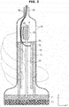
- FIG. 3 is a drawing showing a partially changed structure of the ultrasonic probe illustrated in FIG. 1
- FIG. 4 is a drawing illustrating an image of the ultrasonic probe of FIG. 3 being gripped.
- an ultrasonic probe includes a transducer 10, a heat pipe 20 to facilitate a transfer of the heat generated by the transducer 10, and a radiation unit (also referred to herein as a "radiator") 30 to release the heat transferred via the heat pipe 20 to an exterior of the ultrasonic probe.
- a radiation unit also referred to herein as a "radiator”
- a Magnetostrictive Ultrasonic Transducer which is configured to use a magnetostrictive effect of a magnetic substance that is typically used in conjunction with a conventional probe apparatus, or a Piezoelectric Ultrasonic Transducer, which is configured to use a piezoelectric effect of a piezoelectric substance, may be used.
- a Capacitive Micromachined Ultrasonic Transducer hereinafter referred to as a cMUT, configured to transmit/receive ultrasonic waves by use of vibrations of hundreds or thousands of micromachined thin films, may be also used.
- the heat pipe 20 is configured to facilitate the transfer of the heat generated at the transducer 10 in a y-axis direction, that is, a direction opposite to a radiating direction of ultrasonic waves.
- FIG. 5 is a drawing illustrating an operational principle of the heat pipe 20.
- the heat pipe 20 is an apparatus which is manufactured by injecting working fluid into a sealed container having the shape of a tube and provided to be in a vacuum state.
- the working fluid within the heat pipe 20 is configured to transfer heat while being present in two phases.
- An evaporation of the working fluid occurs at a surface of a wick 22 even at a low temperature in the interior of the heat pipe 20, which is provided with a high pressure.
- Density and pressure of gas are increased at the evaporation unit 21 due to the evaporation of the working fluid, and thus, at a central portion, a gradation of the pressure is formed at a gas flow path toward a direction of a condensation unit (also referred to herein as a "condenser") 22 at which density and pressure of the gas are relatively lower, and as a result, the gas is moved.
- a condensation unit also referred to herein as a "condenser”
- the gas being moved carries an amount of heat which is equivalent to an amount of the latent heat that is evaporated.
- Heat is released as the gas which is moved to the condensation unit 22 is condensed at an inner wall of the condensation unit, which is provided with a relatively lower temperature, and then the gas is returned to a liquid state.
- the working fluid that is returned to the liquid state is moved again toward the evaporation unit 21 through air pores at an interior of the wick 22 by a capillary force of the wick 22 or by a gravitational force.
- the evaporation unit 21 of the heat pipe 20 is installed such that the evaporation unit 21 is in contact with a heat spreader 11 that is configured to absorb the heat which is generated at the transducer 10, and the heat pipe 10 is configured to transfer the heat generated at the transducer 10 to a rear portion of the ultrasonic probe by performance of the heat transfer processes that are described above.
- the heat spreader 11 may be formed with a metallic material having a relatively high heat conductivity, such as aluminum.
- the heat spreader 11 thermally contacts with respect to the transducer 10 at which heat is generated, and is configured to absorb the heat that is generated at the transducer 10.
- the heat pipe 20 is configured to make contact with respect to the heat spreader 11 while inserted into the heat spreader 11 by a predetermined depth so as to effectively facilitate a transfer of the heat absorbed by the heat spreader 11.
- the heat transferred through the heat pipe 20 is released to an exterior of the ultrasonic probe through the radiation unit 30 which is provided at the condensation unit 22 of the heat pipe 20.
- the radiation unit 30 includes a plurality of fins 31 which have the shape of a panel while formed with metallic material so as to scatter the heat transferred from the heat pipe 20.
- the condensation unit 22 of the heat pipe 20 is configured to make contact with respect to the fins 31 of the radiation unit 30, and when heat is released as the gas being moved to the condensation unit 22 is condensed at an inner wall of the condensation unit 22 at which the temperature is relatively low, the heat that is released from the condensation unit 22 of the heat pipe 20 is scattered by the fins 31.
- a radiation fan 40 may be adjacently provided at the radiation unit 30.
- the radiation fan 40 is configured to release the heat, which is scattered by the radiation fins 31, to the exterior so as to additionally enhance radiation performance.
- a housing 70 is provided so as to form a case of the ultrasonic probe, and as illustrated on FIG. 1 , a plurality of vent holes 60 through which air may pass may be formed at the housing 70 so as to cover the space in which the radiation unit 30 is provided.
- the heat being released from the radiation unit 30 may be discharged to the outside as a result of ventilations of air through the vent holes 60.
- the radiation fan 40 may be able to assist so as to increase an effectiveness of the discharging of heat by generating a forced current.
- vent holes 60 As the vent holes 60 are formed, outside air may be drawn in to an interior of the housing 70 through the vent holes 60, and at this time, dust or foreign substance may also be drawn in through the vent holes 60.
- the drawing in of the dust or the foreign substance as such may negatively affect an electrical apparatus 110, such as a printed circuit board provided at an interior of the ultrasonic probe, and thus, as illustrated on FIG. 1 , by installing a partition wall 50 in an interior of the housing 70, the space in which the electrical apparatus 110 is situated may be isolated, so that the difficulty as such may be solved.
- an electrical apparatus 110 such as a printed circuit board provided at an interior of the ultrasonic probe
- vent holes 60 are formed at a portion of the housing 70 which is adjacent to the radiation unit 30, and thus, the partition wall 50 is provided at a position so to separate the radiation unit 30 from the electrical apparatus 110.
- the radiation unit 30 is separated from the electrical apparatus 110 by the partition wall 50, and a cable 80 configured to apply electrical signals to the heat pipe 20 and the electrical apparatus 110 and/or to receive electrical signals from the electrical apparatus 110 is provided so as to penetrate the partition wall 50.
- the cable 80 electrically connected to the electrical apparatus 110 is extended to an exterior of the ultrasonic probe through a cable extension unit (also referred to herein as a "cable extender" 90 which is provided at the rear end of the ultrasonic probe.
- a cable extension unit also referred to herein as a "cable extender” 90 which is provided at the rear end of the ultrasonic probe.
- the cable extension unit 90 is provided at a central portion of the rear end of the ultrasonic probe, but the cable extension unit 90 may be eccentrically provided at the rear end of the ultrasonic probe such that the cable 80 may be prevented from interfering with respect to the heat pipe 20 and/or the radiation unit 30. The above may be confirmed at the ultrasonic probe illustrated on FIG. 2 .
- the portion at which the transducer 10 is provided is defined as the front end of the heat spreader 11, and the opposite side, that is, the portion at which the cable extension unit 90 is provided, is defined as the rear end of the ultrasonic probe.
- a radiation fin 100 provided so as to make contact with respect to the heat spreader 11 and configured to release the heat absorbed at the heat spreader 11 may be provided.
- the two units of the radiation fin 100 may be adjacently provided at an inner side surface of the housing 70, and the radiation fin 100 may be formed with a metallic material which has a relatively high heat conductivity, such as, for example, aluminum.
- the radiation fin 100 is configured to release the heat absorbed at the heat spreader 11 by use of heat conductivity through the housing 70 to an exterior of the housing 70.
- the heat conductivity of the radiation fin 100 is larger than the heat conductivity of the housing 70 and as the heat conductivity of the housing 70 is larger than the heat conductivity of outside air, the heat of the radiation fin 100 is transferred and released to the exterior of the housing 70 by means of heat conductivity through the housing 70.
- FIG. 2 an image of the ultrasonic probe illustrated in FIG. 1 being grabbed by use of a hand is illustrated.
- the shape of the hand grabbing the ultrasonic probe is illustrated with dotted lines.
- a user of the ultrasonic probe may be able to grab the ultrasonic probe so as to avoid covering a portion at which the vent holes 60 are formed as to further efficiently release heat, and the shape of the housing may be designed as to facilitate the grabbing as such.
- the ultrasonic probe shown in FIG. 3 is referred to as an alternative exemplary embodiment with respect to the ultrasonic probe illustrated on FIG. 1 , and the heat pipe 20 is connected to an area that is off-center with respect to the central portion of the heat spreader 11.
- vent holes 60 are formed at the rear end portion of the housing 70 in an area which is adjacent to the radiation unit 30, while in FIG. 3 , the heat pipe 20 is eccentrically installed with respect to the heat spreader 11, and thus, the vent holes 60 are formed only at one portion of surface of the housing 70, that is, at a portion of the housing 70 that is adjacent to the radiation unit 30.
- vent holes 60 are formed at the rear end of the housing 70, and on FIG. 3 , the vent holes 60 are formed in vertical directions from one side surface of the housing 70.
- the partition wall 50 is installed in an interior of the housing 70.
- the partition wall 50 is provided so as to protect the electrical apparatus 110 from the dust or foreign substance which is drawn in from an outside, and as illustrated on FIG. 3 , the partition wall 50 may be formed along the y-axis direction.
- the radiation unit 30 and the electrical apparatus 110 are separated from one another by the partition wall 50, while the heat pipe 20 is provided so as to penetrate a portion of the partition wall 50.
- the electrical apparatus 110 and/or the radiation fin 100 may be eccentrically provided at an opposite domain with respect to the domain at which the heat pipe 20 is installed.
- the cable extension unit 90 at which the cable 80 is extended to an outside is eccentrically provided at the rear end of the ultrasonic probe as well, and subsequently, the cable 80 may be prevented from interfering with respect to the heat pipe 20 and the radiation unit 30.
- FIG. 6 is a drawing schematically illustrating a structure of another exemplary embodiment of the ultrasonic probe
- FIG. 7 and FIG. 8 are drawings schematically showing respective alternative structures of the ultrasonic probe illustrated on FIG. 6
- FIG. 9 is a drawing schematically illustrating a structure of still another exemplary embodiment of the ultrasonic probe.
- FIG. 6 , FIG. 7 , FIG. 8 , and FIG. 9 are provided as to illustrate the heat pipe 20 and the radiation unit 30 as primary structures while omitting other structures other than the heat pipe 20 and the radiation unit 30 by comparison with the structures of the ultrasonic probe illustrated in FIG. 1 , FIG. 2 , FIG. 3 , and FIG. 4 .
- the partition wall 50 configured to separate the electrical apparatus 110 and the radiation unit 30 is installed in the ultrasonic probe shown in FIG. 1 , while the partition wall 50 as such is not installed in the ultrasonic probe shown in FIG. 6 .
- vent holes 60 configured to communicate air are formed at a portion of the housing 70 which covers the radiation unit 30, outside air may be drawn in to an interior of the housing 70 through the vent holes 60, and at this time, along with the inlet of the air, outside dust or foreign substance may be drawn in to the interior of the housing 70.
- the inlet of the foreign substance or dust may negatively affect the printed circuit board and the electrical apparatus 110 provided at the interior of the ultrasonic probe, and may induce malfunctions of the ultrasonic probe.
- the partition wall 50 shown in FIG. 1 is not present, and as the radiation unit 30, which is connected to the heat pipe 20, is installed so as to divide an inside space of the housing 70 of the ultrasonic probe, the radiation unit 30 is provided to perform the function of the partition wall 50 as well as the function of the radiation unit 30.
- the radiation unit 30, in performing the function of the partition wall 50 is provided to block the space, at which the electrical apparatus 110 is provided, from an outside space that is being connected through the vent holes 60.
- the appropriate size of the radiation unit 30 should be manufactured or determined by considering the area of a cross section of an interior of the housing 70, and the shape of the radiation unit 30 should also be manufactured or determined by considering the area of a cross section of the interior of the housing 70.
- the radiation unit 30 includes the plurality of radiation fins 31 which are provided with the shape of a panel that is formed with a metallic material, such as aluminum, such that the heat transferred via the heat pipe 20 may be scattered.
- the condensation unit 22 of the heat pipe 20 is provided so as to make contact with respect to the plurality of radiation fins 31 of the radiation unit 30, and when the heat is released from the gas which is being moved to the condensation unit 22 as the gas is condensed at an inner wall of the condensation unit which is provided with a relatively lower temperature, the heat being released from the condensation unit 22 of the heat pipe 20 is scattered at the radiation fins 31.
- the radiation fin 40 which is configured to release the heat that is scattered from the radiation fins 31, may be adjacently provided with respect to the radiation unit 30.
- the cable extension unit 90 may be eccentrically provided at the rear end of the ultrasonic probe so as to prevent the cable 80 from interfering with respect to the heat pipe 20 and the radiation unit 30.
- the radiation fin 100 configured to release the heat being absorbed from the heat spreader 11 while being in contact with respect to the heat spreader 11 may be provided, so as to further enhance the radiation performance.
- the two units of the fin 100 may be adjacently provided with respect to an inner side surface of the housing 70, and the fin 100 may be formed with a metallic material having a relatively high heat conductivity, such as, for example, aluminum.
- the fin 100 is configured to discharge the heat that is absorbed form the heat spreader 11 by means of heat conductivity via the housing 70.
- FIG. 7 is provided to show an alternative exemplary embodiment of the ultrasonic probe shown in FIG. 6 .
- the shape of the radiation unit 30, which is connected to the heat pipe 20 so as to scatter the heat that is transferred via the heat pipe 20, is provided to be different with respect to the radiation unit 30 shown in FIG. 6 .
- the radiation unit 30 shown in FIG. 6 is structured with the plurality of radiation fins 31 having the shape of a panel while formed with a metallic material such as aluminum
- the radiation unit 30 shown in FIG. 7 is provided with a shape which corresponds to the shape of the rear end of the housing 70 that corresponds to the radiation unit 30.
- the shape of the radiation unit 30 is formed with the shape of a semicircle that is convex with respect to the y-axis as well.
- the shape of the radiation unit 30 and the shape of the rear end of the housing 70 which covers the radiation unit 30 are identical with respect to each other, and thus the radiation unit 30 may be able to be installed at further adjacent position with respect to the housing 70.
- the gap between the radiation unit 30 and the housing 70 may be narrowed.
- the releasing of heat through the vent holes 60 may occur faster as compared to when the gap between the radiation unit 30 and the housing 70 is widened.
- the radiation unit 30 illustrated in FIG. 7 is provided to perform the function of the partition wall 50, similarly as the radiation unit 30 illustrated in FIG. 6 is provided to perform the function of the partition wall 50.
- vent holes 60 which are provided so as to communicate air are formed at the portion of the housing 70 which covers the radiation unit 30, outside air may be able to be drawn in to an interior of the housing 70 through the vent holes 60, and at this time, outside dust or foreign substance may also be drawn into the interior the housing 70 in conjunction with the inlet of the outside air.
- the inletting of the foreign substance or dust may negatively affect the electrical apparatus 110, such as, for example, a printed circuit board which is provided at an interior of the ultrasonic probe, and this may induce malfunctions of the ultrasonic probe.
- the partition wall 50 shown on FIG. 1 is not present, and as the radiation unit 30 connected to the heat pipe 20 is installed so as to divide an inside space of the housing 70 of the ultrasonic probe, the radiation unit 30 is provided to perform the function of the partition wall 50 as well as the function of the radiation unit 30.
- the radiation unit 30, with respect to its function as the partition wall 50 is provided to block the space at which the electrical apparatus 110 is provided from an outside space that is connected through the vent holes 60.
- the size of the radiation unit 30 should be manufactured or determined by considering the area of a cross section of the interior of the housing 70, and the shape of the radiation unit 30 should also be manufactured or determined by considering the area of a cross section of the interior of the housing 70.
- the radiation unit 30 may be formed with a metallic material, such as, for example, aluminum, so as to scatter the heat that is transferred via the heat pipe 20.
- the cable extension unit 90 is provided at a central portion of the rear end of the ultrasonic probe, but the cable extension unit 90 may be eccentrically provided at the rear end of the ultrasonic probe such that the cable 80 may be prevented from interfering with respect to the heat pipe 20 and/or the radiation unit 30.
- FIG. 8 is provided to show an alternative exemplary embodiment of the ultrasonic probe shown in FIG. 7 .
- the shape of the radiation unit 30 shown in FIG. 8 is provided with a shape that corresponds to the shape of the rear end of the portion of the housing 70 which covers the radiation unit 30.
- the radiation unit 30 is formed with the shape of a semicircle that is convex with respect to the y-axis as well.
- the shape of the radiation unit 30 and the shape of the rear end of the portion of the housing 70 which covers the radiation unit 30 are identical with respect to each other, and thus the radiation unit 30 may be able to be installed in close correspondence with respect to the housing 70.
- the gap between the radiation unit 30 and the housing 70 may be narrowed.
- the releasing of heat through heat conductivity may be considered as an effective method of releasing heat.
- vent holes 60 are not formed at the rear end of the housing 70 adjacent to the radiation unit 30 so as to release heat through heat conductivity.
- the radiation unit 30 is formed with a metallic material having relatively high heat conductivity such as aluminum, and thus heat is released to the exterior by use of heat conductivity via the housing 70, which has a lower heat conductivity with respect to the radiation unit 30.
- the heat conductivity of the radiation unit 30 is greater than the heat conductivity of the housing 70, and because the heat conductivity of the housing 70 is greater than the heat conductivity of outside air, the heat of the radiation unit 30 is transferred and released to the exterior of the housing 70 by means of heat conductivity through the housing 70.
- vent holes 60 When the vent holes 60 are not formed, the likelihood of dust or foreign substance being drawn in from outside through the vent holes 60 is reduced, and thus the size and/or the shape of the radiation unit 30 being designed to separate a space within the interior of the housing 70 is not necessarily required.
- the vent holes 60 may be formed at the rear end of the housing 70 adjacent to the radiation unit 30. However, by having the gap between the vent holes 60 larger than the gap between the vent holes 60 as illustrated in FIG. 7 , the vent holes 60 may be sparsely distributed.
- the size of the radiation unit 30 should be manufactured or determined by considering the area of a cross section of an interior portion of the housing 70, and the shape of the radiation unit 30 should also be manufactured or determined by considering the area of a cross section of an interior portion of the housing 70.
- the cable extension unit 90 is provided at a central portion of the rear end of the ultrasonic probe, but the cable extension unit 90 may be eccentrically provided at the rear end of the ultrasonic probe such that the cable 80 may be prevented from interfering with respect to the heat pipe 20 and/or the radiation unit 30.
- FIG. 9 a structure in accordance with another exemplary embodiment of the ultrasonic probe is schematically illustrated.
- the housing 70 of the ultrasonic probe includes a first housing 71 and a second housing 72, and the second housing 72 is formed with a metallic material having a relatively high heat conductivity, such as, for example, aluminum.
- the heat pipe 20 is connected to the second housing 72, and the heat that is transferred through the heat pipe 20 after being absorbed at the heat spreader 11 is released to an outside through the second housing 72.
- the second housing 72 is provided to perform the function of the radiation unit 30.
- the vent holes 60 are not formed at the second housing 72 for effective heat radiation, and because the vent holes 60 are not formed, the partition wall 50 configured to separate the space in which the electrical apparatus 110 is provided is not installed as well.
- FIG. 10 is a perspective view separately illustrating only the second housing 72, which is configured to perform the function of the radiation unit 30 as described above.
- a hole 91 at which the cable extension unit 90 is to be formed is eccentrically formed at a rear end of the second housing 72.
- a circle 29 illustrated in dotted line shows a portion to which the heat pipe 20 is to be connected.
- the portion at which the cable extension unit 90 is formed is eccentrically provided so as to prevent the cable 80 from interfering with respect to the heat pipe 20.
- the cable extension unit 90 is eccentrically formed at the rear end of the second housing 72 of the ultrasonic probe.
- the heat stability of an ultrasonic probe can be enhanced by effectively releasing heat to an outside while the heat is generated by the ultrasonic probe.
Landscapes
- Health & Medical Sciences (AREA)
- Life Sciences & Earth Sciences (AREA)
- Physics & Mathematics (AREA)
- General Health & Medical Sciences (AREA)
- Engineering & Computer Science (AREA)
- Pathology (AREA)
- Radiology & Medical Imaging (AREA)
- Surgery (AREA)
- Veterinary Medicine (AREA)
- Public Health (AREA)
- Biophysics (AREA)
- Nuclear Medicine, Radiotherapy & Molecular Imaging (AREA)
- Animal Behavior & Ethology (AREA)
- Biomedical Technology (AREA)
- Heart & Thoracic Surgery (AREA)
- Medical Informatics (AREA)
- Molecular Biology (AREA)
- General Physics & Mathematics (AREA)
- Analytical Chemistry (AREA)
- Chemical & Material Sciences (AREA)
- Biochemistry (AREA)
- Immunology (AREA)
- Ultra Sonic Daignosis Equipment (AREA)
- Computer Networks & Wireless Communication (AREA)
- Radar, Positioning & Navigation (AREA)
- Remote Sensing (AREA)
- Cooling Or The Like Of Semiconductors Or Solid State Devices (AREA)
Claims (11)
- Ultraschallsonde, umfassend:ein Gehäuse (70);einen Wandler (10), der dazu konfiguriert ist, Ultraschallwellen zu erzeugen, während er in einem Inneren des Gehäuses angeordnet ist;ein Wärmerohr (20), das dazu konfiguriert ist, eine Übertragung von Wärme zu bewerkstelligen, die von dem Wandler erzeugt wird;einen Heizkörper (30), der mit dem Wärmerohr verbunden und dazu konfiguriert ist, die Wärme, die über das Wärmerohr übertragen wird, an einer Außenseite des Gehäuses freizugeben;eine Trennwand (50), die einen Innenraum innerhalb des Gehäuses abtrennt; undeine elektrische Vorrichtung (110), die in dem Innenraum des Gehäuses angeordnet ist,dadurch gekennzeichnet, dassdie Trennwand (50) einen ersten Raum, in dem die elektrische Vorrichtung (110) angeordnet ist, von einem zweiten Raum trennt, in dem der Heizkörper (30) angeordnet ist;wobei die Ultraschallsonde des Weiteren umfasst:ein Kabel (80), das elektrisch mit der elektrischen Vorrichtung verbunden ist; undeine Kabelverlängerung (90), die in einem hinteren Abschnitt des Gehäuses angeordnet ist, um das Kabel zur Außenseite des Gehäuses zu verlängern,wobei die Kabelverlängerung exzentrisch an dem hinteren Abschnitt der Ultraschallsonde angeordnet ist, so dass sie den Heizkörper nicht beeinträchtigt und das Wärmerohr nicht beeinträchtigt, und so, dass verhindert wird, dass das Kabel (80) das Wärmerohr (20) und die Heizeinheit (30) beeinträchtigt.
- Ultraschallsonde nach Anspruch 1, wobei:
das Wärmerohr des Weiteren dazu konfiguriert ist, die Übertragung der von dem Wandler erzeugten Wärme in einer ersten Richtung zu bewerkstelligen, die von einer Strahlungsrichtung der erzeugten Ultraschallwellen um mindestens 90 Grad abweicht. - Ultraschallsonde nach Anspruch 1 oder 2, wobei:
eine Belüftungsöffnung (60), die dazu konfiguriert ist, einen Durchgang von Luft hindurch zu ermöglichen, an dem Gehäuse vorgesehen und des Weiteren dazu konfiguriert ist, den Heizkörper abzudecken. - Ultraschallsonde nach Anspruch 1, wobei:
der Heizkörper eine Strahlungsrippe (100) umfasst, die dazu konfiguriert ist, die über das Wärmerohr übertragene Wärme zu verbreiten. - Ultraschallsonde nach Anspruch 4, des Weiteren umfassend:
einen Strahlungslüfter (40), der dazu konfiguriert ist, die von der Strahlungsrippe verbreitete Wärme zur Außenseite des Gehäuses freizugeben. - Ultraschallsonde nach Anspruch 1, wobei:
das Gehäuse (70) umfasst:ein erstes Gehäuse (71); undein zweites Gehäuse(72), das mit dem Wärmerohr verbunden und dazu konfiguriert ist, die Wärme, die über das Wärmerohr übertragen wird, an einer Außenseite des zweiten Gehäuses freizugeben. - Ultraschallsonde nach Anspruch 6, wobei:
das zweite Gehäuse aus mindestens einem aus Aluminium, Kupfer und einer Legierung aus Aluminium und Kupfer besteht. - Verfahren zum Verteilen von Wärme, die von einer Ultraschallsonde erzeugt wird, wobei die Ultraschallsonde ein Gehäuse (70) und einen Wandler (10) beinhaltet, der dazu konfiguriert ist, Ultraschallwellen zu erzeugen, und wobei das Verfahren umfasst:Positionieren eines Wärmerohrs (20) so, dass eine Übertragung der Wärme ermöglicht wird, die von dem Wandler erzeugt wird; undVerbinden eines Heizkörpers (30) mit dem Wärmerohr, damit die von der Ultraschallsonde erzeugte Wärme an eine Außenseite des Gehäuses übertragen werden kann;gekennzeichnet durchPositionieren einer Trennwand (50) so, dass ein erster Raum in dem Gehäuse, in dem eine elektrische Vorrichtung (110) angeordnet ist, von einem zweiten Raum isoliert wird, in dem der Heizkörper angeordnet ist;elektrisches Verbinden eines Kabels (80) mit der elektrischen Vorrichtung; undBereitstellen einer Kabelverlängerung (90) an einem hinteren Abschnitt des Gehäuses, um das Kabel zur Außenseite des Gehäuses zu verlängern,wobei die Kabelverlängerung (90) exzentrisch an dem hinteren Abschnitt der Ultraschallsonde angeordnet ist, so dass sie den Heizkörper nicht beeinträchtigt und das Wärmerohr (20) nicht beeinträchtigt, und so, dass verhindert wird, dass das Kabel (80) das Wärmerohr (20) und die Heizeinheit (30) beeinträchtigt.
- Verfahren nach Anspruch 8, wobei das Positionieren des Wärmerohrs des Weiteren das Positionieren des Wärmerohrs solcherart umfasst, dass die Übertragung der von dem Wandler erzeugten Wärme in einer ersten Richtung ermöglicht wird, die von einer Strahlungsrichtung der erzeugten Ultraschallwellen um mindestens 90 Grad abweicht.
- Verfahren nach einem der Ansprüche 8 oder 9, wobei der Heizkörper eine Strahlungsrippe beinhaltet, die dazu konfiguriert ist, die über das Wärmerohr übertragene Wärme zu verbreiten.
- Verfahren nach einem der Ansprüche 8 bis 9, wobei der Heizkörper des Weiteren einen Strahlungslüfter beinhaltet, und wobei das Verbinden des Heizkörpers mit dem Wärmerohr des Weiteren das Positionieren des Strahlungslüfters auf solche Weise beinhaltet, dass das Drängen der verbreiteten Wärme durch das Wärmerohr in Richtung der Außenseite des Gehäuses ermöglicht wird.
Applications Claiming Priority (1)
| Application Number | Priority Date | Filing Date | Title |
|---|---|---|---|
| KR1020140044454A KR20150118496A (ko) | 2014-04-14 | 2014-04-14 | 초음파 프로브 |
Publications (2)
| Publication Number | Publication Date |
|---|---|
| EP2932906A1 EP2932906A1 (de) | 2015-10-21 |
| EP2932906B1 true EP2932906B1 (de) | 2018-06-06 |
Family
ID=52997222
Family Applications (1)
| Application Number | Title | Priority Date | Filing Date |
|---|---|---|---|
| EP15163301.3A Not-in-force EP2932906B1 (de) | 2014-04-14 | 2015-04-13 | Ultraschallsonde |
Country Status (5)
| Country | Link |
|---|---|
| US (1) | US10368845B2 (de) |
| EP (1) | EP2932906B1 (de) |
| JP (1) | JP2015202401A (de) |
| KR (1) | KR20150118496A (de) |
| CN (1) | CN104970826A (de) |
Families Citing this family (19)
| Publication number | Priority date | Publication date | Assignee | Title |
|---|---|---|---|---|
| KR101496173B1 (ko) * | 2014-04-17 | 2015-02-26 | 주식회사 힐세리온 | 휴대용 초음파 진단장치의 방열구조 |
| JP6122090B1 (ja) * | 2015-11-26 | 2017-04-26 | 株式会社日立製作所 | 超音波プローブ |
| JP6578196B2 (ja) * | 2015-11-26 | 2019-09-18 | 株式会社日立製作所 | 超音波プローブ |
| KR102578755B1 (ko) * | 2016-01-28 | 2023-09-15 | 삼성메디슨 주식회사 | 초음파 프로브 및 이를 포함한 초음파 진단 시스템 |
| EP3479769B1 (de) | 2016-06-30 | 2023-08-02 | FUJIFILM Corporation | Ultraschallendoskop und verfahren zur herstellung davon |
| JP6787021B2 (ja) * | 2016-10-11 | 2020-11-18 | 日立金属株式会社 | ケーブル |
| KR101953309B1 (ko) * | 2016-11-07 | 2019-02-28 | 삼성메디슨 주식회사 | 초음파 진단 장치용 프로브 |
| CN106725605A (zh) * | 2017-02-23 | 2017-05-31 | 倪丽 | 一种多功能妇产科临床用产前诊断治疗仪 |
| CN109725063A (zh) * | 2017-10-27 | 2019-05-07 | 深圳开立生物医疗科技股份有限公司 | 超声波探头 |
| JP6548234B2 (ja) * | 2017-11-30 | 2019-07-24 | ゼネラル・エレクトリック・カンパニイ | 超音波プローブ及び超音波画像表示装置 |
| KR102607018B1 (ko) * | 2018-01-31 | 2023-11-29 | 삼성메디슨 주식회사 | 초음파 프로브 |
| CN108201658B (zh) * | 2018-02-28 | 2024-02-13 | 谭本 | 一种冷却式超声波治疗头 |
| WO2020077637A1 (zh) * | 2018-10-19 | 2020-04-23 | 深圳迈瑞生物医疗电子股份有限公司 | 一种超声探头、超声探头电缆线和面阵超声探头 |
| CN110479687B (zh) * | 2019-08-01 | 2022-04-15 | 合肥国轩高科动力能源有限公司 | 一种动力电池铝壳的超声清洗装置 |
| FR3110251B1 (fr) * | 2020-05-15 | 2022-05-13 | Supersonic Imagine | Sonde avec chambre de refroidissement |
| US11937984B2 (en) * | 2020-08-25 | 2024-03-26 | GE Precision Healthcare LLC | Active ingress detection system for medical probes |
| CN112790790A (zh) * | 2020-12-23 | 2021-05-14 | 居天医疗科技(深圳)有限公司 | 基于ai识别的运动关节损伤检测设备 |
| US12357280B2 (en) | 2021-04-01 | 2025-07-15 | Koninklijke Philips N.V. | Heat dissipation in ultrasound probes |
| CN113203798A (zh) * | 2021-05-13 | 2021-08-03 | 东北大学 | 一种用于岩石破裂信息采集的耐高温高压声发射装置 |
Family Cites Families (17)
| Publication number | Priority date | Publication date | Assignee | Title |
|---|---|---|---|---|
| JPS582666U (ja) | 1981-06-29 | 1983-01-08 | 横河電機株式会社 | 超音波プロ−ブ |
| JPH0180107U (de) | 1987-11-19 | 1989-05-30 | ||
| US5560362A (en) * | 1994-06-13 | 1996-10-01 | Acuson Corporation | Active thermal control of ultrasound transducers |
| EP1707122B1 (de) | 2004-09-24 | 2010-04-21 | Kabushiki Kaisha Toshiba | Ultraschallsonde |
| US20060173344A1 (en) * | 2005-01-19 | 2006-08-03 | Siemens Medical Solutions Usa, Inc. | Method for using a refrigeration system to remove waste heat from an ultrasound transducer |
| CN101166472A (zh) | 2005-04-25 | 2008-04-23 | 皇家飞利浦电子股份有限公司 | 具有改进的热管理的超声波换能器组件 |
| JP2007209699A (ja) | 2006-02-13 | 2007-08-23 | Toshiba Corp | 超音波プローブ |
| US8221324B2 (en) * | 2006-05-05 | 2012-07-17 | Worcester Polytechnic Institute | Reconfigurable wireless ultrasound diagnostic system |
| JP2008284003A (ja) | 2007-05-15 | 2008-11-27 | Aloka Co Ltd | 超音波プローブ |
| JP2009160068A (ja) | 2007-12-28 | 2009-07-23 | Konica Minolta Medical & Graphic Inc | 超音波探触子およびそれを用いる超音波診断装置 |
| JP2009165509A (ja) | 2008-01-10 | 2009-07-30 | Konica Minolta Medical & Graphic Inc | 超音波診断装置 |
| JP5258493B2 (ja) | 2008-10-07 | 2013-08-07 | 株式会社東芝 | 超音波プローブ |
| US8273025B2 (en) | 2010-05-13 | 2012-09-25 | Kabushiki Kaisha Toshiba | Ultrasound probe |
| JP5904732B2 (ja) | 2011-09-01 | 2016-04-20 | 株式会社東芝 | 超音波プローブ及び超音波診断装置 |
| KR101330733B1 (ko) | 2012-04-30 | 2013-11-20 | 삼성전자주식회사 | 초음파 프로브 |
| KR20140144464A (ko) | 2013-06-11 | 2014-12-19 | 삼성전자주식회사 | 휴대용 초음파 프로브 |
| KR20140144420A (ko) | 2013-06-11 | 2014-12-19 | 삼성전자주식회사 | 초음파 프로브 및 그 제조방법 |
-
2014
- 2014-04-14 KR KR1020140044454A patent/KR20150118496A/ko not_active Ceased
-
2015
- 2015-02-04 US US14/613,769 patent/US10368845B2/en not_active Expired - Fee Related
- 2015-02-06 JP JP2015022275A patent/JP2015202401A/ja active Pending
- 2015-04-07 CN CN201510162239.3A patent/CN104970826A/zh active Pending
- 2015-04-13 EP EP15163301.3A patent/EP2932906B1/de not_active Not-in-force
Non-Patent Citations (1)
| Title |
|---|
| None * |
Also Published As
| Publication number | Publication date |
|---|---|
| US10368845B2 (en) | 2019-08-06 |
| US20150289852A1 (en) | 2015-10-15 |
| EP2932906A1 (de) | 2015-10-21 |
| KR20150118496A (ko) | 2015-10-22 |
| CN104970826A (zh) | 2015-10-14 |
| JP2015202401A (ja) | 2015-11-16 |
Similar Documents
| Publication | Publication Date | Title |
|---|---|---|
| US10368845B2 (en) | Ultrasonic probe | |
| KR101330733B1 (ko) | 초음파 프로브 | |
| US10085717B2 (en) | Ultrasonic probe | |
| US9419202B2 (en) | Ultrasound transducer and method for manufacturing an ultrasound transducer | |
| EP2891525B1 (de) | Ultraschallsonde | |
| CN103417247B (zh) | 超声换能器和用于制造超声换能器的方法 | |
| KR102400997B1 (ko) | 초음파 프로브 및 그 작동 방법과 거치대 | |
| KR20140144420A (ko) | 초음파 프로브 및 그 제조방법 | |
| US20160174939A1 (en) | Ultrasonic probe | |
| KR20150006519A (ko) | 초음파 프로브 및 그 제조방법 | |
| KR20150118750A (ko) | 초음파 영상 장치 | |
| EP3143612B1 (de) | Akustische linse und ultraschallwandlersonde | |
| KR20140144464A (ko) | 휴대용 초음파 프로브 | |
| US20150115773A1 (en) | Ultrasound transducer and method for manufacturing an ultrasound transducer | |
| US9642597B2 (en) | Ultrasonic diagnostic instrument and manufacturing method thereof | |
| CN103239259A (zh) | 超声探头及其制造方法 | |
| KR20160084255A (ko) | 초음파 프로브 및 그 제조방법 | |
| CN110013267A (zh) | 超声探头 | |
| US20200261063A1 (en) | Ultrasonic probe and ultrasonic diagnostic device | |
| KR101586297B1 (ko) | 초음파 프로브 및 그 제조방법 |
Legal Events
| Date | Code | Title | Description |
|---|---|---|---|
| PUAI | Public reference made under article 153(3) epc to a published international application that has entered the european phase |
Free format text: ORIGINAL CODE: 0009012 |
|
| AK | Designated contracting states |
Kind code of ref document: A1 Designated state(s): AL AT BE BG CH CY CZ DE DK EE ES FI FR GB GR HR HU IE IS IT LI LT LU LV MC MK MT NL NO PL PT RO RS SE SI SK SM TR |
|
| AX | Request for extension of the european patent |
Extension state: BA ME |
|
| 17P | Request for examination filed |
Effective date: 20160421 |
|
| RBV | Designated contracting states (corrected) |
Designated state(s): AL AT BE BG CH CY CZ DE DK EE ES FI FR GB GR HR HU IE IS IT LI LT LU LV MC MK MT NL NO PL PT RO RS SE SI SK SM TR |
|
| STAA | Information on the status of an ep patent application or granted ep patent |
Free format text: STATUS: EXAMINATION IS IN PROGRESS |
|
| 17Q | First examination report despatched |
Effective date: 20170213 |
|
| GRAP | Despatch of communication of intention to grant a patent |
Free format text: ORIGINAL CODE: EPIDOSNIGR1 |
|
| STAA | Information on the status of an ep patent application or granted ep patent |
Free format text: STATUS: GRANT OF PATENT IS INTENDED |
|
| INTG | Intention to grant announced |
Effective date: 20171116 |
|
| GRAS | Grant fee paid |
Free format text: ORIGINAL CODE: EPIDOSNIGR3 |
|
| GRAA | (expected) grant |
Free format text: ORIGINAL CODE: 0009210 |
|
| STAA | Information on the status of an ep patent application or granted ep patent |
Free format text: STATUS: THE PATENT HAS BEEN GRANTED |
|
| AK | Designated contracting states |
Kind code of ref document: B1 Designated state(s): AL AT BE BG CH CY CZ DE DK EE ES FI FR GB GR HR HU IE IS IT LI LT LU LV MC MK MT NL NO PL PT RO RS SE SI SK SM TR |
|
| REG | Reference to a national code |
Ref country code: GB Ref legal event code: FG4D |
|
| REG | Reference to a national code |
Ref country code: CH Ref legal event code: EP Ref country code: AT Ref legal event code: REF Ref document number: 1005164 Country of ref document: AT Kind code of ref document: T Effective date: 20180615 |
|
| REG | Reference to a national code |
Ref country code: IE Ref legal event code: FG4D |
|
| REG | Reference to a national code |
Ref country code: DE Ref legal event code: R096 Ref document number: 602015011594 Country of ref document: DE |
|
| REG | Reference to a national code |
Ref country code: NL Ref legal event code: FP |
|
| REG | Reference to a national code |
Ref country code: LT Ref legal event code: MG4D |
|
| PG25 | Lapsed in a contracting state [announced via postgrant information from national office to epo] |
Ref country code: ES Free format text: LAPSE BECAUSE OF FAILURE TO SUBMIT A TRANSLATION OF THE DESCRIPTION OR TO PAY THE FEE WITHIN THE PRESCRIBED TIME-LIMIT Effective date: 20180606 Ref country code: CY Free format text: LAPSE BECAUSE OF FAILURE TO SUBMIT A TRANSLATION OF THE DESCRIPTION OR TO PAY THE FEE WITHIN THE PRESCRIBED TIME-LIMIT Effective date: 20180606 Ref country code: LT Free format text: LAPSE BECAUSE OF FAILURE TO SUBMIT A TRANSLATION OF THE DESCRIPTION OR TO PAY THE FEE WITHIN THE PRESCRIBED TIME-LIMIT Effective date: 20180606 Ref country code: BG Free format text: LAPSE BECAUSE OF FAILURE TO SUBMIT A TRANSLATION OF THE DESCRIPTION OR TO PAY THE FEE WITHIN THE PRESCRIBED TIME-LIMIT Effective date: 20180906 Ref country code: FI Free format text: LAPSE BECAUSE OF FAILURE TO SUBMIT A TRANSLATION OF THE DESCRIPTION OR TO PAY THE FEE WITHIN THE PRESCRIBED TIME-LIMIT Effective date: 20180606 Ref country code: NO Free format text: LAPSE BECAUSE OF FAILURE TO SUBMIT A TRANSLATION OF THE DESCRIPTION OR TO PAY THE FEE WITHIN THE PRESCRIBED TIME-LIMIT Effective date: 20180906 Ref country code: SE Free format text: LAPSE BECAUSE OF FAILURE TO SUBMIT A TRANSLATION OF THE DESCRIPTION OR TO PAY THE FEE WITHIN THE PRESCRIBED TIME-LIMIT Effective date: 20180606 |
|
| PG25 | Lapsed in a contracting state [announced via postgrant information from national office to epo] |
Ref country code: GR Free format text: LAPSE BECAUSE OF FAILURE TO SUBMIT A TRANSLATION OF THE DESCRIPTION OR TO PAY THE FEE WITHIN THE PRESCRIBED TIME-LIMIT Effective date: 20180907 Ref country code: LV Free format text: LAPSE BECAUSE OF FAILURE TO SUBMIT A TRANSLATION OF THE DESCRIPTION OR TO PAY THE FEE WITHIN THE PRESCRIBED TIME-LIMIT Effective date: 20180606 Ref country code: RS Free format text: LAPSE BECAUSE OF FAILURE TO SUBMIT A TRANSLATION OF THE DESCRIPTION OR TO PAY THE FEE WITHIN THE PRESCRIBED TIME-LIMIT Effective date: 20180606 Ref country code: HR Free format text: LAPSE BECAUSE OF FAILURE TO SUBMIT A TRANSLATION OF THE DESCRIPTION OR TO PAY THE FEE WITHIN THE PRESCRIBED TIME-LIMIT Effective date: 20180606 |
|
| REG | Reference to a national code |
Ref country code: AT Ref legal event code: MK05 Ref document number: 1005164 Country of ref document: AT Kind code of ref document: T Effective date: 20180606 |
|
| PG25 | Lapsed in a contracting state [announced via postgrant information from national office to epo] |
Ref country code: CZ Free format text: LAPSE BECAUSE OF FAILURE TO SUBMIT A TRANSLATION OF THE DESCRIPTION OR TO PAY THE FEE WITHIN THE PRESCRIBED TIME-LIMIT Effective date: 20180606 Ref country code: SK Free format text: LAPSE BECAUSE OF FAILURE TO SUBMIT A TRANSLATION OF THE DESCRIPTION OR TO PAY THE FEE WITHIN THE PRESCRIBED TIME-LIMIT Effective date: 20180606 Ref country code: PL Free format text: LAPSE BECAUSE OF FAILURE TO SUBMIT A TRANSLATION OF THE DESCRIPTION OR TO PAY THE FEE WITHIN THE PRESCRIBED TIME-LIMIT Effective date: 20180606 Ref country code: RO Free format text: LAPSE BECAUSE OF FAILURE TO SUBMIT A TRANSLATION OF THE DESCRIPTION OR TO PAY THE FEE WITHIN THE PRESCRIBED TIME-LIMIT Effective date: 20180606 Ref country code: IS Free format text: LAPSE BECAUSE OF FAILURE TO SUBMIT A TRANSLATION OF THE DESCRIPTION OR TO PAY THE FEE WITHIN THE PRESCRIBED TIME-LIMIT Effective date: 20181006 Ref country code: EE Free format text: LAPSE BECAUSE OF FAILURE TO SUBMIT A TRANSLATION OF THE DESCRIPTION OR TO PAY THE FEE WITHIN THE PRESCRIBED TIME-LIMIT Effective date: 20180606 Ref country code: AT Free format text: LAPSE BECAUSE OF FAILURE TO SUBMIT A TRANSLATION OF THE DESCRIPTION OR TO PAY THE FEE WITHIN THE PRESCRIBED TIME-LIMIT Effective date: 20180606 |
|
| PG25 | Lapsed in a contracting state [announced via postgrant information from national office to epo] |
Ref country code: SM Free format text: LAPSE BECAUSE OF FAILURE TO SUBMIT A TRANSLATION OF THE DESCRIPTION OR TO PAY THE FEE WITHIN THE PRESCRIBED TIME-LIMIT Effective date: 20180606 Ref country code: IT Free format text: LAPSE BECAUSE OF FAILURE TO SUBMIT A TRANSLATION OF THE DESCRIPTION OR TO PAY THE FEE WITHIN THE PRESCRIBED TIME-LIMIT Effective date: 20180606 |
|
| REG | Reference to a national code |
Ref country code: DE Ref legal event code: R097 Ref document number: 602015011594 Country of ref document: DE |
|
| PLBE | No opposition filed within time limit |
Free format text: ORIGINAL CODE: 0009261 |
|
| STAA | Information on the status of an ep patent application or granted ep patent |
Free format text: STATUS: NO OPPOSITION FILED WITHIN TIME LIMIT |
|
| 26N | No opposition filed |
Effective date: 20190307 |
|
| PG25 | Lapsed in a contracting state [announced via postgrant information from national office to epo] |
Ref country code: SI Free format text: LAPSE BECAUSE OF FAILURE TO SUBMIT A TRANSLATION OF THE DESCRIPTION OR TO PAY THE FEE WITHIN THE PRESCRIBED TIME-LIMIT Effective date: 20180606 Ref country code: DK Free format text: LAPSE BECAUSE OF FAILURE TO SUBMIT A TRANSLATION OF THE DESCRIPTION OR TO PAY THE FEE WITHIN THE PRESCRIBED TIME-LIMIT Effective date: 20180606 |
|
| PG25 | Lapsed in a contracting state [announced via postgrant information from national office to epo] |
Ref country code: AL Free format text: LAPSE BECAUSE OF FAILURE TO SUBMIT A TRANSLATION OF THE DESCRIPTION OR TO PAY THE FEE WITHIN THE PRESCRIBED TIME-LIMIT Effective date: 20180606 |
|
| REG | Reference to a national code |
Ref country code: CH Ref legal event code: PL |
|
| REG | Reference to a national code |
Ref country code: BE Ref legal event code: MM Effective date: 20190430 |
|
| GBPC | Gb: european patent ceased through non-payment of renewal fee |
Effective date: 20190413 |
|
| PG25 | Lapsed in a contracting state [announced via postgrant information from national office to epo] |
Ref country code: MC Free format text: LAPSE BECAUSE OF FAILURE TO SUBMIT A TRANSLATION OF THE DESCRIPTION OR TO PAY THE FEE WITHIN THE PRESCRIBED TIME-LIMIT Effective date: 20180606 Ref country code: LU Free format text: LAPSE BECAUSE OF NON-PAYMENT OF DUE FEES Effective date: 20190413 |
|
| PG25 | Lapsed in a contracting state [announced via postgrant information from national office to epo] |
Ref country code: GB Free format text: LAPSE BECAUSE OF NON-PAYMENT OF DUE FEES Effective date: 20190413 Ref country code: CH Free format text: LAPSE BECAUSE OF NON-PAYMENT OF DUE FEES Effective date: 20190430 Ref country code: LI Free format text: LAPSE BECAUSE OF NON-PAYMENT OF DUE FEES Effective date: 20190430 |
|
| PG25 | Lapsed in a contracting state [announced via postgrant information from national office to epo] |
Ref country code: BE Free format text: LAPSE BECAUSE OF NON-PAYMENT OF DUE FEES Effective date: 20190430 |
|
| PG25 | Lapsed in a contracting state [announced via postgrant information from national office to epo] |
Ref country code: TR Free format text: LAPSE BECAUSE OF FAILURE TO SUBMIT A TRANSLATION OF THE DESCRIPTION OR TO PAY THE FEE WITHIN THE PRESCRIBED TIME-LIMIT Effective date: 20180606 |
|
| PG25 | Lapsed in a contracting state [announced via postgrant information from national office to epo] |
Ref country code: IE Free format text: LAPSE BECAUSE OF NON-PAYMENT OF DUE FEES Effective date: 20190413 |
|
| PGFP | Annual fee paid to national office [announced via postgrant information from national office to epo] |
Ref country code: NL Payment date: 20200323 Year of fee payment: 6 |
|
| PG25 | Lapsed in a contracting state [announced via postgrant information from national office to epo] |
Ref country code: PT Free format text: LAPSE BECAUSE OF FAILURE TO SUBMIT A TRANSLATION OF THE DESCRIPTION OR TO PAY THE FEE WITHIN THE PRESCRIBED TIME-LIMIT Effective date: 20181008 |
|
| PGFP | Annual fee paid to national office [announced via postgrant information from national office to epo] |
Ref country code: FR Payment date: 20200325 Year of fee payment: 6 |
|
| PGFP | Annual fee paid to national office [announced via postgrant information from national office to epo] |
Ref country code: DE Payment date: 20200320 Year of fee payment: 6 |
|
| PG25 | Lapsed in a contracting state [announced via postgrant information from national office to epo] |
Ref country code: HU Free format text: LAPSE BECAUSE OF FAILURE TO SUBMIT A TRANSLATION OF THE DESCRIPTION OR TO PAY THE FEE WITHIN THE PRESCRIBED TIME-LIMIT; INVALID AB INITIO Effective date: 20150413 Ref country code: MT Free format text: LAPSE BECAUSE OF FAILURE TO SUBMIT A TRANSLATION OF THE DESCRIPTION OR TO PAY THE FEE WITHIN THE PRESCRIBED TIME-LIMIT Effective date: 20180606 |
|
| REG | Reference to a national code |
Ref country code: DE Ref legal event code: R119 Ref document number: 602015011594 Country of ref document: DE |
|
| REG | Reference to a national code |
Ref country code: NL Ref legal event code: MM Effective date: 20210501 |
|
| PG25 | Lapsed in a contracting state [announced via postgrant information from national office to epo] |
Ref country code: DE Free format text: LAPSE BECAUSE OF NON-PAYMENT OF DUE FEES Effective date: 20211103 Ref country code: FR Free format text: LAPSE BECAUSE OF NON-PAYMENT OF DUE FEES Effective date: 20210430 |
|
| PG25 | Lapsed in a contracting state [announced via postgrant information from national office to epo] |
Ref country code: NL Free format text: LAPSE BECAUSE OF NON-PAYMENT OF DUE FEES Effective date: 20210501 |
|
| PG25 | Lapsed in a contracting state [announced via postgrant information from national office to epo] |
Ref country code: MK Free format text: LAPSE BECAUSE OF FAILURE TO SUBMIT A TRANSLATION OF THE DESCRIPTION OR TO PAY THE FEE WITHIN THE PRESCRIBED TIME-LIMIT Effective date: 20180606 |