EP2932841B1 - Ausbringfahrzeug - Google Patents
Ausbringfahrzeug Download PDFInfo
- Publication number
- EP2932841B1 EP2932841B1 EP15401028.4A EP15401028A EP2932841B1 EP 2932841 B1 EP2932841 B1 EP 2932841B1 EP 15401028 A EP15401028 A EP 15401028A EP 2932841 B1 EP2932841 B1 EP 2932841B1
- Authority
- EP
- European Patent Office
- Prior art keywords
- hydraulic
- applier
- flow
- vehicle according
- sides
- Prior art date
- Legal status (The legal status is an assumption and is not a legal conclusion. Google has not performed a legal analysis and makes no representation as to the accuracy of the status listed.)
- Not-in-force
Links
Images


Classifications
-
- A—HUMAN NECESSITIES
- A01—AGRICULTURE; FORESTRY; ANIMAL HUSBANDRY; HUNTING; TRAPPING; FISHING
- A01M—CATCHING, TRAPPING OR SCARING OF ANIMALS; APPARATUS FOR THE DESTRUCTION OF NOXIOUS ANIMALS OR NOXIOUS PLANTS
- A01M7/00—Special adaptations or arrangements of liquid-spraying apparatus for purposes covered by this subclass
- A01M7/005—Special arrangements or adaptations of the spraying or distributing parts, e.g. adaptations or mounting of the spray booms, mounting of the nozzles, protection shields
- A01M7/0053—Mounting of the spraybooms
- A01M7/0057—Mounting of the spraybooms with active regulation of the boom position
Definitions
- the invention relates to a Ausbringhus specified in the preamble of claim 1. Art.
- Such application vehicles are, for example, field sprayers or tractors with attached booms for spraying, wherein the boom can have a working width of more than 20 meters.
- the linkage has center-symmetrical extensions and carries, for example, downwardly directed nozzles for dispensing a spray, wherein a varying distance of the nozzles from the bottom results in non-uniform application.
- Rolling movements of the application vehicle about a longitudinal axis oriented in the vehicle direction should not, or as little as possible, be transferred to the linkage.
- the largely ground-parallel setting of the linkage should be maintained even with asymmetric projection of the linkage, for example, in one-sided collapsed linkage sections.
- the hydraulic actuator assembly is controlled so that resulting from roll motions of Ausbringhuss via the pressure source via the hydraulic valve on the pressurized admission side almost incompressible hydraulic medium column resulting moments that seek to bring the linkage from the ground-parallel position. This requires high control engineering effort and a quick control intervention.
- EP 2 591 657 A1 an even higher-quality control electronics is used to pick up, among other things, rolling movements of the application vehicle via sensors and to track the hydraulic actuator arrangements even substantially in real time.
- This complex control electronics and the sensors are expensive and error-prone due to the complexity.
- virtually permanent tracking movements take place, so that the hydraulic actuator assembly can not transmit parasitic forces or moments in the linkage.
- the linkage is movable via a plurality of joints and, inter alia, a chain relative to the application vehicle, wherein the hydraulic actuator assembly between a supported on the vehicle knee joint suspension of the linkage and the linkage is arranged.
- the invention has for its object to improve a Ausbring scholar of the type mentioned in that a ground-parallel pivot position of the linkage is easier to adjust and durable, and with little control engineering effort rolling motions of Ausbringhuss be kept away from the linkage or efficiently attenuated.
- the at least one adjustable hydraulic element sets a constant, constant volumetric flow, and from this volumetric flow with the elements adjustable in passage cross-section the individual pressures are set on the admission sides, whereby a permanent circulation takes place, there is no clamped incompressible hydraulic medium column, which is the floor-parallel pivoting position cancel or Wankschulen the Ausbringhuss substantially unattenuated transferred to the linkage, but is a kind of yielding floating position with permanent inflow and outflow to and from the Beauftschungs publish ago.
- the at least one flow control valve adjusts the permanent and constant volume flow, and the individual pressures at the admission sides are set from this volume flow via the control throttles.
- the control throttles make it possible with control technology little effort, if necessary, yet to produce individual pressures on the admission sides.
- the variable throttle not only allow the individual pressure setting, but also produce a very effective damping of forces or moments by consuming energy from the hydraulic medium via the respectively effective pressure difference on them.
- the adjustment of the control inductors via the control electronics for example, depending on the equality or inequality between the sensor signals, and affects the system with a selectable, but relatively small delay.
- the respective damping or the response can be easily adjusted by tuning adjust the set flow rate and the variable reactors to the given requirements.
- a simple adjustment of the volume flow can also be achieved by means of at least one hydraulic pump delivering a variable hydraulic flow.
- the value of the set with the at least one flow control valve or the hydraulic pump volume flow is selectable, for example via the control electronics, or on an adjustment or directly on the flow control valve.
- the flow control valve generates the desired constant volume flow independently of pressure fluctuations upstream and downstream and also with fluctuating viscosity of the hydraulic medium.
- the hydraulic actuator assembly is either a double-acting hydraulic actuator with the first and second Beauftschungshow, for example, a double-acting hydraulic cylinder or a reversible hydraulic motor, or there are two single-acting, counteracting hydraulic actuators each provided with a Beaufschlagungsseite.
- the admission sides are transversely connected with each other, so that the hydraulic medium displaced at an admission side can be fed to the other admission side.
- This is expediently carried out via a connecting line, in which preferably a throttle is contained in order to influence the exchange between the Beaufschlagungsbeat.
- the throttle may be a fixed throttle, or an actuating throttle, for example, a manually or electromagnetically adjustable throttle. This throttle also desirably affects damping performance and helps to minimize the consumption of hydraulic fluid and to prevent the hydraulic actuator assembly from vacuuming during abrupt movements.
- the center of gravity of the linkage is also arranged at a distance below the axis, so that resulting from rolling movements of AusbringInstitutes transverse movements are not transmitted directly into the linkage, as given the inertia of the linkage in the manner of a pendulum, an additional degree of freedom about the axis. This does not preclude placing the axle approximately at the center of gravity of the linkage.
- a flow control valve and, in separate outflow paths from the admission sides, one adjusting throttle each are arranged in a branching off to the admission sides, this common inflow path upstream of the branching.
- This embodiment is structurally and control technology simple. Due to the direct connection of the admission sides, although no extreme pressure differences between the admission sides can be realized, for most applications, however, different pressures are sufficient.
- a respective flow control valve is arranged in a branching off to the admission sides, this common Zuströmweg downstream of the branching in both Zuströmweg branches and a separate control throttle in separate outflow from the Beaufschlagungstress. This embodiment makes it possible to adjust the pressure on each admission side individually and independently of the pressure on the other admission side.
- a flow divider valve instead of the two flow control valves at the junction of the inflow path, a flow divider valve is used which sets a constant volume flow in each inflow branch.
- the volume flows can be the same.
- flow divider valves can be used, the division ratio can vary.
- the pressure adjustment and the damping take place at a constant inflow and a variable outflow, respectively.
- a variable inflow and substantially constant downflow is used, in which in a branching to the Beauftschungslose, this common Zuströmweg upstream of the branch a flow control valve and in each Zuströmweg branches each an actuating throttle and in separate outflow from the Beaufschlagungsze ever a fixed throttle are arranged.
- This embodiment is suitably combined with a connection between the Beauftschungsh in which a fixed throttle or constant aperture is arranged so that hydraulic medium can be exchanged between the Beaufscherungsh.
- the control throttles and the fixed throttles interact mutually.
- At least the actuating choke is arranged in a solenoid-operated valve whose magnet can be controlled by the control electronics.
- a proportional magnet is used here, whose magnetic force is proportional to the supplied current or the voltage, so that the throttle cross-section of the actuating choke is varied steplessly.
- This solenoid-operated valve is operated, for example, with hydraulic pilot control to get along with a small-build and relatively weak magnet.
- a Wegaufillonvorraum be provided to provide the control electronics feedback for proper adjustment.
- another drive can be used to adjust the actuating choke.
- the flow control valve is expediently, for example, a two-way flow regulator and / or combined from a pressure compensator and a throttle valve in poppet or slide valve design.
- a manual or hydraulic or magnetic adjustment device may be provided for the volume flow.
- control electronics is at least adjustable or programmed for operating modes, for horizontal terrain, for slopes and for an asymmetric boom projection.
- the two control chokes may be set equal to set equal pressures on both sides of the impeller and to efficiently dampen roll motions of the application vehicle due to uneven ground.
- the two control inductors can be set accordingly different, e.g. taking into account the center of gravity below the axis, whereby the rod could be deflected around the axis in the manner of a pendulum, which is avoided by the different pressures.
- a difference between the phasing choke settings is chosen from the outset, depending on the magnitude of the asymmetry.
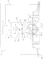
- Fig. 1 is a schematic rear view or front view of a AusbringInstituts F, eg a field sprayer with a transverse to the direction (in the plane) oriented, usually symmetrically on both sides of a frame 5 cantilevered linkage 1, of which a central part 2 and, for example, hingedly arranged jib parts 3 are indicated.
- the application vehicle F may be designed to be self-propelled (eg on wheels R), or to be towed or towed.
- the linkage 1 could be attached to a tractor.
- the AusbringInstitut F has the optionally adjustable in its height frame 5, to which the linkage 1, z. B. with the frame 5, about a substantially oriented in the direction of travel axis 4 is pivotable.
- the center of gravity G of the linkage 1 at a distance below the axis 4 lie.
- the linkage 1 When deploying the linkage 1 should assume a pivotal position about the axis 4, in which it is oriented at least substantially parallel to the ground. This also applies to the application in a laterally inclined slope or asymmetric projection of the linkage, for example, because one or more boom sections 3 is collapsed on one side or are.
- a hydraulic actuator assembly 6 between the AusbringInstitut F, or its frame 5, and the linkage 1 is provided.
- the hydraulic actuator assembly 6 in FIG Fig. 1 comprises two on one side on an admission side 13, 14 acted upon by hydraulic pressure mutually-operating hydraulic actuators 7, 8 typically hydraulic cylinders.
- a direction of rotation reversible hydraulic motor could be used with two drivable opposite directions of rotation hydraulic motors.
- the hydraulic actuator 7 is pivotally supported on the frame 5 in a linkage 11 and the linkage 1 or its middle part 2 in a linkage 12, wherein the linkage 12 is further outward than the articulation 11, and the linkages 11, 12 in approximately have the same radial distance from the axis 4.
- the hydraulic actuator 8 is mirror-inverted in linkages 11 ', 12' supported.
- the Beaufscherungstress 13, 14 are each connected via a line 9, 10 with a hydraulic system, not shown.
- At least on the linkage 1 sensors S are provided, e.g. Distance sensors that are connected to a control electronics CU signal transmitting.
- the sensor system may comprise further sensors on the application vehicle F and / or linkage 1, e.g. Tilt sensors and the like.
- the control electronics CU is also connected at least to the hydraulic system of the hydraulic actuator assembly 6.
- Purpose of the hydraulic actuators assembly 6 is to keep the linkage 1 under different operating conditions at least substantially parallel to the ground and also taking advantage of the inertia of learnauskragenden linkage 1 during rolling movements of AusbringInstituts F on uneven ground their influence on the pivotal position of the linkage efficiently dampen or compensate.
- the embodiment of the Fig. 2 is different from that of Fig. 1 mainly in that the hydraulic actuator assembly 6 is designed differently, with two unilaterally acted upon hydraulic actuators 7, 8, which are supported on the linkage 1 and its middle part 2 in a common linkage 12, while their linkages 11, 11 'are placed approximately between the center of gravity G and the axis 4 on the frame 5.
- Fig. 3 are the two unilaterally acted hydraulic actuators 7, 8 arranged approximately horizontally on the linkage 1 and its middle part 12 z. B. supported above the center of gravity G and the axis 4 in the common linkage 12, however, on the frame 5 on outer linkages 11, 11 '.
- the focus G of the linkage 1 is here z. B. at least substantially in the axis. 4
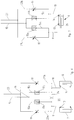
- Fig. 4 illustrates a simple embodiment of the hydraulic system of the hydraulic actuators 7,8 of the embodiments of the Fig. 1 to 3 ,
- the hydraulic system is connected, for example, to an inflow path 15, which is assigned jointly to the admission sides 13, 14, to a pressure source P and via a common outflow path 23 to a tank T (return flow).
- the inflow 15 includes a flow control valve 17, with the constant constant flow independent of pressure fluctuations upstream or downstream of the Beauftschungstress 13, 14 but also to the constantly open Ruströmweg 23 can be generated.
- the value of the volume flow can be adjustable, in adaptation to different operating or equipment conditions.
- the inflow path 15 branches at a junction 16 with inflow branch branches 15a, 15b to the lines 9, 10 to the admission sides 13, 14.
- the lines 9, 10 are further connected to Ragströmweg branches 23a, 23b, in each of which a control throttle 18 and 19 is arranged, which are adjustable via the control electronics CU, so that their throttle cross-section can optionally be changed continuously.
- hydraulic fluid circulates in the hydraulic system.
- the hydraulic medium circulates permanently with the set flow in the hydraulic system, wherein at the same setting control throttles 18, 19 due to the pressure differences generated by these same pressures on the Beauftschungshunt 13, 14 are constructed and the rod 1 is set parallel to the ground and is held as long as the sensors S do not provide different signals.
- the sensors S supply different signals, which indicate, for example, that the linkage 1 is lower on the side of the hydraulic actuator 7 than on the opposite side, then the throttling cross section of the control throttle 18 is reduced (possibly optionally) via the control electronics CU at the same time the throttle cross-section of the control throttle 19 increases), so that the Beaufschlagungsseite 13 receives higher pressure than the Beaufschlagungsseite 14 until the linkage 1 is set again in the ground-parallel pivot position.
- Rolling motions of the application vehicle F due to uneven ground occurring about the longitudinal axis are initially attenuated by hydraulic means, even using the inertia of the linkage 1, so that the ground-parallel position of the linkage 1 does not appreciably change.
- stagger in Fig. 1 the Ausbringhus F to the right, because the left wheels R pass over a survey, then the hydraulic actuator 7 is inserted and the hydraulic actuator 8 pulled out.
- the pressure at the admission side 13 increases and hydraulic fluid is expelled, of which a part flows through the control throttle 18 and attenuates and a part to the other hydraulic actuator 8 is displaced or causes the volume flow to the side of the hydraulic actuator 8 and the pressure on the admission side 14 rise briefly.
- the linkage 1 is essentially still kept parallel to the ground. At least a large part of the energy resulting from this rolling movement is consumed in the adjusting throttles 18, 19, which causes efficient damping. Nevertheless, should the linkage 1 develop the tendency to give up the ground-parallel pivotal position about the axis 4, an adjustment of at least one of the actuating throttles 18, 19 made on the control electronics CU based on the sensor signals to counteract this tendency or to eliminate them.
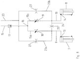
- the embodiment Fig. 5 is that the Fig. 2 similar.
- the hydraulic system of the two hydraulic actuators 7, 8 is different from that of the Fig. 4
- the common inflow path 15 which branches off at the junction 16 into the inflow branch branches 15a, 15b, contains a flow control valve 17a, 17b in each inflow branch 15a, 15b.
- a control throttle 18 is also arranged here, which is adjustable via the control electronics CU and lines 20.
- the sensors S on the linkage 1 are connected via a line 21 to the control electronics CU of the application vehicle F.
- a flow divider 22 indicated by dashed lines, the same constant in the two Zuströmweg branches 15a, 15b Volume flow sets.
- the hydraulic system upstream of the flow divider 22 may be designed so that the flow divider already receives a constant volume flow, which he divides, for example, in equal parts. In this way, separate flow control valves 17a, 17b can be saved.
- the admission sides 13, 14 are not directly connected to each other. Nevertheless, the ground-parallel pivoting position is easily adjusted and maintained and rolling movements of the application vehicle F are damped or compensated.
- the sensors provide identical values, there is a floor-parallel pivot position. If the value of the sensor S on the left side, for example, greater than the value of the sensor S on the right side, the control electronics CU reduces the throttle cross section of the control throttle 18 and increases the throttle cross section of the control throttle 19. Due to this change in the throttle cross sections, the pressure p1 increases on the loading side 13 against the decreasing pressure p2 on the loading side 14, whereby the pivoting position is returned to a floor-parallel pivoting position again. Since at the same time tunes the hydraulic medium via the control throttles 18, 19, is always attenuated.
- Fig. 6 The embodiment in Fig. 6 is that the Fig. 5 similar.
- the Beauftschungstress 13, 14 and the lines 9, 10 connected via a cross-connection 24 with each other so that an exchange of hydraulic fluid at unequal pressures on the Beaufschlagungstrain 13, 14 is made possible.
- This can minimize the overall required hydraulic fluid flow rate and also prevents a rapid movement of a hydraulic actuator from pulling it to a vacuum.
- a fixed throttle 25 is contained in the connection 24, which is tuned in its passage cross-section to the respectively set volume flow or the passage cross section of the control throttle 18 or 19.
- the fixed throttle 25 could alternatively be adjustable, for example, be designed as a simple throttle screw.
- An exchange of hydraulic medium is similar, as based on Fig. 4 explained, however, the fixed throttle 25 can set significantly different pressures at the Beauftschungstrain 13, 14.
- Fig. 7 shows an embodiment of the hydraulic system similar to that of Fig. 5 ,
- the hydraulic actuator assembly 6 does not comprise two single-acting and counter-acting hydraulic actuators 7, 8, as in the following embodiments, but a single double-acting hydraulic actuator 26, with both Beaufschlagungslibrary 13, 14.
- the Hydraulic actuator 26 the hydraulic systems according to the Fig. 4 . 5 or 6 be combined.
- the flow control valve 17 is arranged, the permanent set constant flow, which divides into the Zuströmweg branches 15a, 15b.
- the inflow branch branches 15a, 15b each contain an actuating throttle 18, 19.
- the lines 9, 10 or admission sides 13, 14 are here connected via the cross-connection 24 for the exchange of hydraulic medium, preferably via the fixed throttle 25.
- the two Abströmweg branches 23a , 23b each contain a fixed throttle 27.
- the passage cross sections of the fixed throttle 27 may be equal to each other.
- the different pressures at the Beauftschungstress 13, 14 are generated here inter alia from the interaction of the respective control throttle 18 or 19 with its associated fixed throttle 27, wherein the constant volume flow from the flow control valve 17 differs differently, depending on the respective pressure efficiency on the control throttle 18 or 19. Also when damping the system, the control throttles 18 cooperate with the fixed throttles 27, possibly also with the fixed throttle 25.
- the hydraulic system of Fig. 8 can also for a double-acting hydraulic actuator 26 as in Fig. 7 be used.
- the flow control valve 17, 17a, 17b may be formed as a two-way flow control valve, or include a pressure compensator with associated throttle valve.
- This throttle valve could be adjusted by a proportional solenoid (possibly with hydraulic pilot control) in order to change the volume flow as needed.
- the control choke is expediently contained in a throttle valve with a proportional magnet, which can be controlled by the control electronics CU and adjusts the passage cross section proportionally to the current intensity or voltage.
- a transducer could provide feedback for the control electronics.
- a flow divider valve as in Fig. 5 arranged, this could be designed so that it not only divides the incoming flow in equal parts, but also keeps the flow rates constant.
- a steady flow or circulation of the hydraulic medium is generated via the admission sides.
- the pressure at the respective admission side can be varied by means of the adjusting throttles. For example, if the passage cross-section is reduced, the pressure at the Supply side until the amount of hydraulic fluid could flow over the reduced cross-section. This is effectively damped.
- the damping of the hydraulic system can be varied relatively easily. Namely, if the hydraulic actuators are adjusted due to relative movements between the linkage and the application vehicle, displaced hydraulic medium must be dissipated in addition to the permanently set volume flow through the respective outflow cross section.
- the total volume flow which must be dissipated via the discharge cross section, results from the constant volume flow in the inflow path and the temporarily displaced volume flow from the hydraulic actuator.
- the damping of the hydraulic system can be varied.
- the flow control valve for adjusting the individual pressure and at least one variable hydraulic flow supplying hydraulic pump can be used instead of the flow control valve for adjusting the individual pressure and at least one variable hydraulic flow supplying hydraulic pump.
- the hydraulic pump delivered and adjusted volume flow can be selected accordingly by means of suitable adjustment means.
Landscapes
- Life Sciences & Earth Sciences (AREA)
- Engineering & Computer Science (AREA)
- Insects & Arthropods (AREA)
- Pest Control & Pesticides (AREA)
- Wood Science & Technology (AREA)
- Zoology (AREA)
- Environmental Sciences (AREA)
- Vehicle Body Suspensions (AREA)
Priority Applications (1)
| Application Number | Priority Date | Filing Date | Title |
|---|---|---|---|
| PL15401028T PL2932841T3 (pl) | 2014-04-16 | 2015-04-14 | Rozlewacz nawozów płynnych |
Applications Claiming Priority (1)
| Application Number | Priority Date | Filing Date | Title |
|---|---|---|---|
| DE102014105416.4A DE102014105416A1 (de) | 2014-04-16 | 2014-04-16 | Ausbringfahrzeug |
Publications (2)
| Publication Number | Publication Date |
|---|---|
| EP2932841A1 EP2932841A1 (de) | 2015-10-21 |
| EP2932841B1 true EP2932841B1 (de) | 2017-01-25 |
Family
ID=53181228
Family Applications (1)
| Application Number | Title | Priority Date | Filing Date |
|---|---|---|---|
| EP15401028.4A Not-in-force EP2932841B1 (de) | 2014-04-16 | 2015-04-14 | Ausbringfahrzeug |
Country Status (4)
| Country | Link |
|---|---|
| EP (1) | EP2932841B1 (pl) |
| DE (1) | DE102014105416A1 (pl) |
| DK (1) | DK2932841T3 (pl) |
| PL (1) | PL2932841T3 (pl) |
Cited By (3)
| Publication number | Priority date | Publication date | Assignee | Title |
|---|---|---|---|---|
| EP4245136A1 (en) * | 2022-03-15 | 2023-09-20 | Exel Industries SA | A pendulum suspension device of a spray boom and a method of aligning a pendulum suspension device of a spray boom |
| US11980180B2 (en) | 2020-03-04 | 2024-05-14 | Deere & Company | Pendulum boom suspension |
| EP4477046A1 (de) * | 2023-06-15 | 2024-12-18 | HORSCH LEEB Application Systems GmbH | Tragstruktur für ein landwirtschaftliches arbeitsgerät zur ausbringung eines landwirtschaftlichen guts auf einem boden, arbeitsgerät mit einer tragstruktur und verfahren zum ausbringen eines landwirtschaftlichen guts |
Families Citing this family (1)
| Publication number | Priority date | Publication date | Assignee | Title |
|---|---|---|---|---|
| DE102016103864A1 (de) * | 2016-03-03 | 2017-09-07 | Inuma Fahrzeug-Service Und Maschinenbau Gmbh | Arretierungsvorrichtung, Laufwagenvorrichtung und Fahrzeug |
Family Cites Families (5)
| Publication number | Priority date | Publication date | Assignee | Title |
|---|---|---|---|---|
| FR2779031B1 (fr) | 1998-06-02 | 2004-12-03 | Exel Ind | Ensemble de rampe pendulaire, notamment pour engin de pulverisation agricole, equipe d'un dispositif de correction d'inclinaison |
| US7426827B2 (en) * | 2006-06-15 | 2008-09-23 | Cnh Canada, Ltd. | Suspension arrangement for a boom assembly mounted on an agricultural sprayer |
| DE102007025751B4 (de) | 2007-06-01 | 2022-08-25 | Amazonen-Werke H. Dreyer SE & Co. KG | Verteilmaschine |
| EP2591657B1 (de) | 2011-11-08 | 2017-06-28 | HORSCH LEEB Application Systems GmbH | Fahrbare Vorrichtung zum Ausbringen von flüssigen und/oder festen Wirkstoffen und Verfahren zur Steuerung der Vorrichtung |
| FR2996412B1 (fr) * | 2012-10-04 | 2014-12-19 | Gyrland Ind S A S | Dispositif de suspension de rampe de pulverisateur agricole |
-
2014
- 2014-04-16 DE DE102014105416.4A patent/DE102014105416A1/de not_active Withdrawn
-
2015
- 2015-04-14 PL PL15401028T patent/PL2932841T3/pl unknown
- 2015-04-14 EP EP15401028.4A patent/EP2932841B1/de not_active Not-in-force
- 2015-04-14 DK DK15401028.4T patent/DK2932841T3/en active
Non-Patent Citations (1)
| Title |
|---|
| None * |
Cited By (3)
| Publication number | Priority date | Publication date | Assignee | Title |
|---|---|---|---|---|
| US11980180B2 (en) | 2020-03-04 | 2024-05-14 | Deere & Company | Pendulum boom suspension |
| EP4245136A1 (en) * | 2022-03-15 | 2023-09-20 | Exel Industries SA | A pendulum suspension device of a spray boom and a method of aligning a pendulum suspension device of a spray boom |
| EP4477046A1 (de) * | 2023-06-15 | 2024-12-18 | HORSCH LEEB Application Systems GmbH | Tragstruktur für ein landwirtschaftliches arbeitsgerät zur ausbringung eines landwirtschaftlichen guts auf einem boden, arbeitsgerät mit einer tragstruktur und verfahren zum ausbringen eines landwirtschaftlichen guts |
Also Published As
| Publication number | Publication date |
|---|---|
| PL2932841T3 (pl) | 2017-07-31 |
| EP2932841A1 (de) | 2015-10-21 |
| DE102014105416A1 (de) | 2015-10-22 |
| DK2932841T3 (en) | 2017-05-08 |
Similar Documents
| Publication | Publication Date | Title |
|---|---|---|
| EP3449723B1 (de) | Steuer- und/oder regelsystem, landwirtschaftliches nutzfahrzeug und verfahren zur steuerung und/oder regelung | |
| EP3629725B1 (de) | Steuereinrichtung für eine ausbringvorrichtung und ausbringvorrichtung mit einer steuereinrichtung | |
| EP3753407B1 (de) | Landwirtschaftliches gerät mit verbesserter neigungsregelung | |
| EP3468340B1 (de) | Regelvorrichtung, landwirtschaftliches nutzfahrzeug und verfahren zum betreiben eines landwirtschaftlichen nutzfahrzeuges | |
| DE102007047886A1 (de) | Spritzengestänge | |
| EP3075246B1 (de) | Landwirtschaftliche maschine und sicherheitsverfahren | |
| EP2932841B1 (de) | Ausbringfahrzeug | |
| WO2021037517A1 (de) | Landwirtschaftliches gerät mit verbesserter aufhängung | |
| EP3592143B1 (de) | Steuer- und/oder regelsystem, landwirtschaftliches nutzfahrzeug und verfahren zur steuerung und/oder regelung eines landwirtschaftlichen nutzfahrzeugs | |
| EP4212018A1 (de) | Landwirtschaftliches gerät mit verbesserter neigungsregelung | |
| EP3804516B1 (de) | Landwirtschaftliche verteilmaschine, vorzugsweise eine feldspritze oder ein düngerstreuer | |
| DE102020118528A1 (de) | Landwirtschaftliche Verteilmaschine, vorzugsweise eine Feldspritze oder ein Düngerstreuer | |
| EP3975711B1 (de) | Steuer- und/oder regelsystem fuer ein landwirtschaftliches geraet | |
| WO2021037519A1 (de) | Landwirtschaftliches gerät mit verbesserter aufhängung | |
| EP3975712B1 (de) | Steuer- und/oder regelsystem fuer ein landwirtschaftliches geraet | |
| EP3516958B1 (de) | Regelvorrichtung für ein landwirtschaftliches nutzfahrzeug und verfahren zum betreiben des nutzfahrzeugs | |
| EP2597209B1 (de) | Elektronisch-hydraulisches Hubwerksregelsystem | |
| DE202017107372U1 (de) | Landwirtschaftliche Ernte- und/oder Bodenbearbeitungsmaschine | |
| DE102024127593A1 (de) | Landwirtschaftliche Maschine | |
| DE202022002936U1 (de) | Landwirtschaftliches Gerät mit verbesserter Neigungsregelung | |
| DE102006038801A1 (de) | Hydraulische Betätigungseinrichtung | |
| EP4321021A1 (de) | Steuer- und/oder regelsystem, landwirtschaftliches nutzfahrzeug | |
| EP3482631A1 (de) | Steuer- und/oder regelsystem für ein landwirtschaftliches nutzfahrzeug, landwirtschaftliches nutzfahrzeug und verfahren zur steuerung und/oder regelung dafür |
Legal Events
| Date | Code | Title | Description |
|---|---|---|---|
| PUAI | Public reference made under article 153(3) epc to a published international application that has entered the european phase |
Free format text: ORIGINAL CODE: 0009012 |
|
| AK | Designated contracting states |
Kind code of ref document: A1 Designated state(s): AL AT BE BG CH CY CZ DE DK EE ES FI FR GB GR HR HU IE IS IT LI LT LU LV MC MK MT NL NO PL PT RO RS SE SI SK SM TR |
|
| AX | Request for extension of the european patent |
Extension state: BA ME |
|
| 17P | Request for examination filed |
Effective date: 20160413 |
|
| RBV | Designated contracting states (corrected) |
Designated state(s): AL AT BE BG CH CY CZ DE DK EE ES FI FR GB GR HR HU IE IS IT LI LT LU LV MC MK MT NL NO PL PT RO RS SE SI SK SM TR |
|
| GRAP | Despatch of communication of intention to grant a patent |
Free format text: ORIGINAL CODE: EPIDOSNIGR1 |
|
| INTG | Intention to grant announced |
Effective date: 20161020 |
|
| GRAS | Grant fee paid |
Free format text: ORIGINAL CODE: EPIDOSNIGR3 |
|
| GRAA | (expected) grant |
Free format text: ORIGINAL CODE: 0009210 |
|
| AK | Designated contracting states |
Kind code of ref document: B1 Designated state(s): AL AT BE BG CH CY CZ DE DK EE ES FI FR GB GR HR HU IE IS IT LI LT LU LV MC MK MT NL NO PL PT RO RS SE SI SK SM TR |
|
| REG | Reference to a national code |
Ref country code: GB Ref legal event code: FG4D Free format text: NOT ENGLISH |
|
| REG | Reference to a national code |
Ref country code: CH Ref legal event code: EP |
|
| REG | Reference to a national code |
Ref country code: AT Ref legal event code: REF Ref document number: 863566 Country of ref document: AT Kind code of ref document: T Effective date: 20170215 |
|
| REG | Reference to a national code |
Ref country code: IE Ref legal event code: FG4D Free format text: LANGUAGE OF EP DOCUMENT: GERMAN |
|
| REG | Reference to a national code |
Ref country code: DE Ref legal event code: R096 Ref document number: 502015000526 Country of ref document: DE |
|
| REG | Reference to a national code |
Ref country code: FR Ref legal event code: PLFP Year of fee payment: 3 |
|
| REG | Reference to a national code |
Ref country code: NL Ref legal event code: FP |
|
| REG | Reference to a national code |
Ref country code: DK Ref legal event code: T3 Effective date: 20170502 |
|
| REG | Reference to a national code |
Ref country code: LT Ref legal event code: MG4D |
|
| PG25 | Lapsed in a contracting state [announced via postgrant information from national office to epo] |
Ref country code: IS Free format text: LAPSE BECAUSE OF FAILURE TO SUBMIT A TRANSLATION OF THE DESCRIPTION OR TO PAY THE FEE WITHIN THE PRESCRIBED TIME-LIMIT Effective date: 20170525 Ref country code: FI Free format text: LAPSE BECAUSE OF FAILURE TO SUBMIT A TRANSLATION OF THE DESCRIPTION OR TO PAY THE FEE WITHIN THE PRESCRIBED TIME-LIMIT Effective date: 20170125 Ref country code: GR Free format text: LAPSE BECAUSE OF FAILURE TO SUBMIT A TRANSLATION OF THE DESCRIPTION OR TO PAY THE FEE WITHIN THE PRESCRIBED TIME-LIMIT Effective date: 20170426 Ref country code: HR Free format text: LAPSE BECAUSE OF FAILURE TO SUBMIT A TRANSLATION OF THE DESCRIPTION OR TO PAY THE FEE WITHIN THE PRESCRIBED TIME-LIMIT Effective date: 20170125 Ref country code: NO Free format text: LAPSE BECAUSE OF FAILURE TO SUBMIT A TRANSLATION OF THE DESCRIPTION OR TO PAY THE FEE WITHIN THE PRESCRIBED TIME-LIMIT Effective date: 20170425 Ref country code: LT Free format text: LAPSE BECAUSE OF FAILURE TO SUBMIT A TRANSLATION OF THE DESCRIPTION OR TO PAY THE FEE WITHIN THE PRESCRIBED TIME-LIMIT Effective date: 20170125 |
|
| PG25 | Lapsed in a contracting state [announced via postgrant information from national office to epo] |
Ref country code: LV Free format text: LAPSE BECAUSE OF FAILURE TO SUBMIT A TRANSLATION OF THE DESCRIPTION OR TO PAY THE FEE WITHIN THE PRESCRIBED TIME-LIMIT Effective date: 20170125 Ref country code: PT Free format text: LAPSE BECAUSE OF FAILURE TO SUBMIT A TRANSLATION OF THE DESCRIPTION OR TO PAY THE FEE WITHIN THE PRESCRIBED TIME-LIMIT Effective date: 20170525 Ref country code: BG Free format text: LAPSE BECAUSE OF FAILURE TO SUBMIT A TRANSLATION OF THE DESCRIPTION OR TO PAY THE FEE WITHIN THE PRESCRIBED TIME-LIMIT Effective date: 20170425 Ref country code: SE Free format text: LAPSE BECAUSE OF FAILURE TO SUBMIT A TRANSLATION OF THE DESCRIPTION OR TO PAY THE FEE WITHIN THE PRESCRIBED TIME-LIMIT Effective date: 20170125 Ref country code: ES Free format text: LAPSE BECAUSE OF FAILURE TO SUBMIT A TRANSLATION OF THE DESCRIPTION OR TO PAY THE FEE WITHIN THE PRESCRIBED TIME-LIMIT Effective date: 20170125 Ref country code: RS Free format text: LAPSE BECAUSE OF FAILURE TO SUBMIT A TRANSLATION OF THE DESCRIPTION OR TO PAY THE FEE WITHIN THE PRESCRIBED TIME-LIMIT Effective date: 20170125 |
|
| REG | Reference to a national code |
Ref country code: DE Ref legal event code: R097 Ref document number: 502015000526 Country of ref document: DE |
|
| PG25 | Lapsed in a contracting state [announced via postgrant information from national office to epo] |
Ref country code: EE Free format text: LAPSE BECAUSE OF FAILURE TO SUBMIT A TRANSLATION OF THE DESCRIPTION OR TO PAY THE FEE WITHIN THE PRESCRIBED TIME-LIMIT Effective date: 20170125 Ref country code: RO Free format text: LAPSE BECAUSE OF FAILURE TO SUBMIT A TRANSLATION OF THE DESCRIPTION OR TO PAY THE FEE WITHIN THE PRESCRIBED TIME-LIMIT Effective date: 20170125 Ref country code: IT Free format text: LAPSE BECAUSE OF FAILURE TO SUBMIT A TRANSLATION OF THE DESCRIPTION OR TO PAY THE FEE WITHIN THE PRESCRIBED TIME-LIMIT Effective date: 20170125 Ref country code: SK Free format text: LAPSE BECAUSE OF FAILURE TO SUBMIT A TRANSLATION OF THE DESCRIPTION OR TO PAY THE FEE WITHIN THE PRESCRIBED TIME-LIMIT Effective date: 20170125 |
|
| PG25 | Lapsed in a contracting state [announced via postgrant information from national office to epo] |
Ref country code: SM Free format text: LAPSE BECAUSE OF FAILURE TO SUBMIT A TRANSLATION OF THE DESCRIPTION OR TO PAY THE FEE WITHIN THE PRESCRIBED TIME-LIMIT Effective date: 20170125 |
|
| PLBE | No opposition filed within time limit |
Free format text: ORIGINAL CODE: 0009261 |
|
| STAA | Information on the status of an ep patent application or granted ep patent |
Free format text: STATUS: NO OPPOSITION FILED WITHIN TIME LIMIT |
|
| 26N | No opposition filed |
Effective date: 20171026 |
|
| REG | Reference to a national code |
Ref country code: IE Ref legal event code: MM4A |
|
| PG25 | Lapsed in a contracting state [announced via postgrant information from national office to epo] |
Ref country code: MC Free format text: LAPSE BECAUSE OF FAILURE TO SUBMIT A TRANSLATION OF THE DESCRIPTION OR TO PAY THE FEE WITHIN THE PRESCRIBED TIME-LIMIT Effective date: 20170125 |
|
| PG25 | Lapsed in a contracting state [announced via postgrant information from national office to epo] |
Ref country code: SI Free format text: LAPSE BECAUSE OF FAILURE TO SUBMIT A TRANSLATION OF THE DESCRIPTION OR TO PAY THE FEE WITHIN THE PRESCRIBED TIME-LIMIT Effective date: 20170125 Ref country code: LU Free format text: LAPSE BECAUSE OF NON-PAYMENT OF DUE FEES Effective date: 20170414 |
|
| REG | Reference to a national code |
Ref country code: FR Ref legal event code: PLFP Year of fee payment: 4 |
|
| REG | Reference to a national code |
Ref country code: BE Ref legal event code: MM Effective date: 20170430 |
|
| PG25 | Lapsed in a contracting state [announced via postgrant information from national office to epo] |
Ref country code: IE Free format text: LAPSE BECAUSE OF NON-PAYMENT OF DUE FEES Effective date: 20170414 |
|
| PG25 | Lapsed in a contracting state [announced via postgrant information from national office to epo] |
Ref country code: BE Free format text: LAPSE BECAUSE OF NON-PAYMENT OF DUE FEES Effective date: 20170430 |
|
| PGFP | Annual fee paid to national office [announced via postgrant information from national office to epo] |
Ref country code: PL Payment date: 20180315 Year of fee payment: 4 |
|
| PGFP | Annual fee paid to national office [announced via postgrant information from national office to epo] |
Ref country code: CZ Payment date: 20180403 Year of fee payment: 4 Ref country code: DK Payment date: 20180410 Year of fee payment: 4 |
|
| PG25 | Lapsed in a contracting state [announced via postgrant information from national office to epo] |
Ref country code: MT Free format text: LAPSE BECAUSE OF FAILURE TO SUBMIT A TRANSLATION OF THE DESCRIPTION OR TO PAY THE FEE WITHIN THE PRESCRIBED TIME-LIMIT Effective date: 20170125 |
|
| REG | Reference to a national code |
Ref country code: CH Ref legal event code: PL |
|
| PG25 | Lapsed in a contracting state [announced via postgrant information from national office to epo] |
Ref country code: CH Free format text: LAPSE BECAUSE OF NON-PAYMENT OF DUE FEES Effective date: 20180430 Ref country code: LI Free format text: LAPSE BECAUSE OF NON-PAYMENT OF DUE FEES Effective date: 20180430 |
|
| PG25 | Lapsed in a contracting state [announced via postgrant information from national office to epo] |
Ref country code: HU Free format text: LAPSE BECAUSE OF FAILURE TO SUBMIT A TRANSLATION OF THE DESCRIPTION OR TO PAY THE FEE WITHIN THE PRESCRIBED TIME-LIMIT; INVALID AB INITIO Effective date: 20150414 |
|
| PGFP | Annual fee paid to national office [announced via postgrant information from national office to epo] |
Ref country code: NL Payment date: 20190412 Year of fee payment: 5 |
|
| PG25 | Lapsed in a contracting state [announced via postgrant information from national office to epo] |
Ref country code: CY Free format text: LAPSE BECAUSE OF FAILURE TO SUBMIT A TRANSLATION OF THE DESCRIPTION OR TO PAY THE FEE WITHIN THE PRESCRIBED TIME-LIMIT Effective date: 20170125 |
|
| PG25 | Lapsed in a contracting state [announced via postgrant information from national office to epo] |
Ref country code: MK Free format text: LAPSE BECAUSE OF FAILURE TO SUBMIT A TRANSLATION OF THE DESCRIPTION OR TO PAY THE FEE WITHIN THE PRESCRIBED TIME-LIMIT Effective date: 20170125 |
|
| REG | Reference to a national code |
Ref country code: DK Ref legal event code: EBP Effective date: 20190430 |
|
| GBPC | Gb: european patent ceased through non-payment of renewal fee |
Effective date: 20190414 |
|
| PG25 | Lapsed in a contracting state [announced via postgrant information from national office to epo] |
Ref country code: GB Free format text: LAPSE BECAUSE OF NON-PAYMENT OF DUE FEES Effective date: 20190414 Ref country code: CZ Free format text: LAPSE BECAUSE OF NON-PAYMENT OF DUE FEES Effective date: 20190414 |
|
| PG25 | Lapsed in a contracting state [announced via postgrant information from national office to epo] |
Ref country code: TR Free format text: LAPSE BECAUSE OF FAILURE TO SUBMIT A TRANSLATION OF THE DESCRIPTION OR TO PAY THE FEE WITHIN THE PRESCRIBED TIME-LIMIT Effective date: 20170125 |
|
| PG25 | Lapsed in a contracting state [announced via postgrant information from national office to epo] |
Ref country code: DK Free format text: LAPSE BECAUSE OF NON-PAYMENT OF DUE FEES Effective date: 20190430 |
|
| PG25 | Lapsed in a contracting state [announced via postgrant information from national office to epo] |
Ref country code: AL Free format text: LAPSE BECAUSE OF FAILURE TO SUBMIT A TRANSLATION OF THE DESCRIPTION OR TO PAY THE FEE WITHIN THE PRESCRIBED TIME-LIMIT Effective date: 20170125 |
|
| PG25 | Lapsed in a contracting state [announced via postgrant information from national office to epo] |
Ref country code: PL Free format text: LAPSE BECAUSE OF NON-PAYMENT OF DUE FEES Effective date: 20190414 |
|
| REG | Reference to a national code |
Ref country code: NL Ref legal event code: MM Effective date: 20200501 |
|
| PG25 | Lapsed in a contracting state [announced via postgrant information from national office to epo] |
Ref country code: NL Free format text: LAPSE BECAUSE OF NON-PAYMENT OF DUE FEES Effective date: 20200501 |
|
| PGFP | Annual fee paid to national office [announced via postgrant information from national office to epo] |
Ref country code: FR Payment date: 20210310 Year of fee payment: 7 |
|
| REG | Reference to a national code |
Ref country code: DE Ref legal event code: R082 Ref document number: 502015000526 Country of ref document: DE Representative=s name: KILBURN & STRODE LLP, GB Ref country code: DE Ref legal event code: R082 Ref document number: 502015000526 Country of ref document: DE Representative=s name: KILBURN & STRODE LLP, NL Ref country code: DE Ref legal event code: R081 Ref document number: 502015000526 Country of ref document: DE Owner name: AMAZONEN-WERKE H. DREYER SE & CO. KG, DE Free format text: FORMER OWNER: AMAZONEN-WERKE H. DREYER GMBH & CO. KG, 49205 HASBERGEN, DE |
|
| REG | Reference to a national code |
Ref country code: DE Ref legal event code: R082 Ref document number: 502015000526 Country of ref document: DE Representative=s name: KILBURN & STRODE LLP, NL |
|
| REG | Reference to a national code |
Ref country code: AT Ref legal event code: MM01 Ref document number: 863566 Country of ref document: AT Kind code of ref document: T Effective date: 20200414 |
|
| PGFP | Annual fee paid to national office [announced via postgrant information from national office to epo] |
Ref country code: DE Payment date: 20210316 Year of fee payment: 7 |
|
| PG25 | Lapsed in a contracting state [announced via postgrant information from national office to epo] |
Ref country code: AT Free format text: LAPSE BECAUSE OF NON-PAYMENT OF DUE FEES Effective date: 20200414 |
|
| REG | Reference to a national code |
Ref country code: DE Ref legal event code: R119 Ref document number: 502015000526 Country of ref document: DE |
|
| PG25 | Lapsed in a contracting state [announced via postgrant information from national office to epo] |
Ref country code: FR Free format text: LAPSE BECAUSE OF NON-PAYMENT OF DUE FEES Effective date: 20220430 Ref country code: DE Free format text: LAPSE BECAUSE OF NON-PAYMENT OF DUE FEES Effective date: 20221103 |