EP2932841B1 - Ausbringfahrzeug - Google Patents
Ausbringfahrzeug Download PDFInfo
- Publication number
- EP2932841B1 EP2932841B1 EP15401028.4A EP15401028A EP2932841B1 EP 2932841 B1 EP2932841 B1 EP 2932841B1 EP 15401028 A EP15401028 A EP 15401028A EP 2932841 B1 EP2932841 B1 EP 2932841B1
- Authority
- EP
- European Patent Office
- Prior art keywords
- hydraulic
- applier
- flow
- vehicle according
- sides
- Prior art date
- Legal status (The legal status is an assumption and is not a legal conclusion. Google has not performed a legal analysis and makes no representation as to the accuracy of the status listed.)
- Not-in-force
Links
Images


Classifications
-
- A—HUMAN NECESSITIES
- A01—AGRICULTURE; FORESTRY; ANIMAL HUSBANDRY; HUNTING; TRAPPING; FISHING
- A01M—CATCHING, TRAPPING OR SCARING OF ANIMALS; APPARATUS FOR THE DESTRUCTION OF NOXIOUS ANIMALS OR NOXIOUS PLANTS
- A01M7/00—Special adaptations or arrangements of liquid-spraying apparatus for purposes covered by this subclass
- A01M7/005—Special arrangements or adaptations of the spraying or distributing parts, e.g. adaptations or mounting of the spray booms, mounting of the nozzles, protection shields
- A01M7/0053—Mounting of the spraybooms
- A01M7/0057—Mounting of the spraybooms with active regulation of the boom position
Definitions
- the invention relates to a Ausbringhus specified in the preamble of claim 1. Art.
- Such application vehicles are, for example, field sprayers or tractors with attached booms for spraying, wherein the boom can have a working width of more than 20 meters.
- the linkage has center-symmetrical extensions and carries, for example, downwardly directed nozzles for dispensing a spray, wherein a varying distance of the nozzles from the bottom results in non-uniform application.
- Rolling movements of the application vehicle about a longitudinal axis oriented in the vehicle direction should not, or as little as possible, be transferred to the linkage.
- the largely ground-parallel setting of the linkage should be maintained even with asymmetric projection of the linkage, for example, in one-sided collapsed linkage sections.
- the hydraulic actuator assembly is controlled so that resulting from roll motions of Ausbringhuss via the pressure source via the hydraulic valve on the pressurized admission side almost incompressible hydraulic medium column resulting moments that seek to bring the linkage from the ground-parallel position. This requires high control engineering effort and a quick control intervention.
- EP 2 591 657 A1 an even higher-quality control electronics is used to pick up, among other things, rolling movements of the application vehicle via sensors and to track the hydraulic actuator arrangements even substantially in real time.
- This complex control electronics and the sensors are expensive and error-prone due to the complexity.
- virtually permanent tracking movements take place, so that the hydraulic actuator assembly can not transmit parasitic forces or moments in the linkage.
- the linkage is movable via a plurality of joints and, inter alia, a chain relative to the application vehicle, wherein the hydraulic actuator assembly between a supported on the vehicle knee joint suspension of the linkage and the linkage is arranged.
- the invention has for its object to improve a Ausbring scholar of the type mentioned in that a ground-parallel pivot position of the linkage is easier to adjust and durable, and with little control engineering effort rolling motions of Ausbringhuss be kept away from the linkage or efficiently attenuated.
- the at least one adjustable hydraulic element sets a constant, constant volumetric flow, and from this volumetric flow with the elements adjustable in passage cross-section the individual pressures are set on the admission sides, whereby a permanent circulation takes place, there is no clamped incompressible hydraulic medium column, which is the floor-parallel pivoting position cancel or Wankschulen the Ausbringhuss substantially unattenuated transferred to the linkage, but is a kind of yielding floating position with permanent inflow and outflow to and from the Beauftschungs publish ago.
- the at least one flow control valve adjusts the permanent and constant volume flow, and the individual pressures at the admission sides are set from this volume flow via the control throttles.
- the control throttles make it possible with control technology little effort, if necessary, yet to produce individual pressures on the admission sides.
- the variable throttle not only allow the individual pressure setting, but also produce a very effective damping of forces or moments by consuming energy from the hydraulic medium via the respectively effective pressure difference on them.
- the adjustment of the control inductors via the control electronics for example, depending on the equality or inequality between the sensor signals, and affects the system with a selectable, but relatively small delay.
- the respective damping or the response can be easily adjusted by tuning adjust the set flow rate and the variable reactors to the given requirements.
- a simple adjustment of the volume flow can also be achieved by means of at least one hydraulic pump delivering a variable hydraulic flow.
- the value of the set with the at least one flow control valve or the hydraulic pump volume flow is selectable, for example via the control electronics, or on an adjustment or directly on the flow control valve.
- the flow control valve generates the desired constant volume flow independently of pressure fluctuations upstream and downstream and also with fluctuating viscosity of the hydraulic medium.
- the hydraulic actuator assembly is either a double-acting hydraulic actuator with the first and second Beauftschungshow, for example, a double-acting hydraulic cylinder or a reversible hydraulic motor, or there are two single-acting, counteracting hydraulic actuators each provided with a Beaufschlagungsseite.
- the admission sides are transversely connected with each other, so that the hydraulic medium displaced at an admission side can be fed to the other admission side.
- This is expediently carried out via a connecting line, in which preferably a throttle is contained in order to influence the exchange between the Beaufschlagungsbeat.
- the throttle may be a fixed throttle, or an actuating throttle, for example, a manually or electromagnetically adjustable throttle. This throttle also desirably affects damping performance and helps to minimize the consumption of hydraulic fluid and to prevent the hydraulic actuator assembly from vacuuming during abrupt movements.
- the center of gravity of the linkage is also arranged at a distance below the axis, so that resulting from rolling movements of AusbringInstitutes transverse movements are not transmitted directly into the linkage, as given the inertia of the linkage in the manner of a pendulum, an additional degree of freedom about the axis. This does not preclude placing the axle approximately at the center of gravity of the linkage.
- a flow control valve and, in separate outflow paths from the admission sides, one adjusting throttle each are arranged in a branching off to the admission sides, this common inflow path upstream of the branching.
- This embodiment is structurally and control technology simple. Due to the direct connection of the admission sides, although no extreme pressure differences between the admission sides can be realized, for most applications, however, different pressures are sufficient.
- a respective flow control valve is arranged in a branching off to the admission sides, this common Zuströmweg downstream of the branching in both Zuströmweg branches and a separate control throttle in separate outflow from the Beaufschlagungstress. This embodiment makes it possible to adjust the pressure on each admission side individually and independently of the pressure on the other admission side.
- a flow divider valve instead of the two flow control valves at the junction of the inflow path, a flow divider valve is used which sets a constant volume flow in each inflow branch.
- the volume flows can be the same.
- flow divider valves can be used, the division ratio can vary.
- the pressure adjustment and the damping take place at a constant inflow and a variable outflow, respectively.
- a variable inflow and substantially constant downflow is used, in which in a branching to the Beauftschungslose, this common Zuströmweg upstream of the branch a flow control valve and in each Zuströmweg branches each an actuating throttle and in separate outflow from the Beaufschlagungsze ever a fixed throttle are arranged.
- This embodiment is suitably combined with a connection between the Beauftschungsh in which a fixed throttle or constant aperture is arranged so that hydraulic medium can be exchanged between the Beaufscherungsh.
- the control throttles and the fixed throttles interact mutually.
- At least the actuating choke is arranged in a solenoid-operated valve whose magnet can be controlled by the control electronics.
- a proportional magnet is used here, whose magnetic force is proportional to the supplied current or the voltage, so that the throttle cross-section of the actuating choke is varied steplessly.
- This solenoid-operated valve is operated, for example, with hydraulic pilot control to get along with a small-build and relatively weak magnet.
- a Wegaufillonvorraum be provided to provide the control electronics feedback for proper adjustment.
- another drive can be used to adjust the actuating choke.
- the flow control valve is expediently, for example, a two-way flow regulator and / or combined from a pressure compensator and a throttle valve in poppet or slide valve design.
- a manual or hydraulic or magnetic adjustment device may be provided for the volume flow.
- control electronics is at least adjustable or programmed for operating modes, for horizontal terrain, for slopes and for an asymmetric boom projection.
- the two control chokes may be set equal to set equal pressures on both sides of the impeller and to efficiently dampen roll motions of the application vehicle due to uneven ground.
- the two control inductors can be set accordingly different, e.g. taking into account the center of gravity below the axis, whereby the rod could be deflected around the axis in the manner of a pendulum, which is avoided by the different pressures.
- a difference between the phasing choke settings is chosen from the outset, depending on the magnitude of the asymmetry.
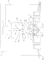
- Fig. 1 is a schematic rear view or front view of a AusbringInstituts F, eg a field sprayer with a transverse to the direction (in the plane) oriented, usually symmetrically on both sides of a frame 5 cantilevered linkage 1, of which a central part 2 and, for example, hingedly arranged jib parts 3 are indicated.
- the application vehicle F may be designed to be self-propelled (eg on wheels R), or to be towed or towed.
- the linkage 1 could be attached to a tractor.
- the AusbringInstitut F has the optionally adjustable in its height frame 5, to which the linkage 1, z. B. with the frame 5, about a substantially oriented in the direction of travel axis 4 is pivotable.
- the center of gravity G of the linkage 1 at a distance below the axis 4 lie.
- the linkage 1 When deploying the linkage 1 should assume a pivotal position about the axis 4, in which it is oriented at least substantially parallel to the ground. This also applies to the application in a laterally inclined slope or asymmetric projection of the linkage, for example, because one or more boom sections 3 is collapsed on one side or are.
- a hydraulic actuator assembly 6 between the AusbringInstitut F, or its frame 5, and the linkage 1 is provided.
- the hydraulic actuator assembly 6 in FIG Fig. 1 comprises two on one side on an admission side 13, 14 acted upon by hydraulic pressure mutually-operating hydraulic actuators 7, 8 typically hydraulic cylinders.
- a direction of rotation reversible hydraulic motor could be used with two drivable opposite directions of rotation hydraulic motors.
- the hydraulic actuator 7 is pivotally supported on the frame 5 in a linkage 11 and the linkage 1 or its middle part 2 in a linkage 12, wherein the linkage 12 is further outward than the articulation 11, and the linkages 11, 12 in approximately have the same radial distance from the axis 4.
- the hydraulic actuator 8 is mirror-inverted in linkages 11 ', 12' supported.
- the Beaufscherungstress 13, 14 are each connected via a line 9, 10 with a hydraulic system, not shown.
- At least on the linkage 1 sensors S are provided, e.g. Distance sensors that are connected to a control electronics CU signal transmitting.
- the sensor system may comprise further sensors on the application vehicle F and / or linkage 1, e.g. Tilt sensors and the like.
- the control electronics CU is also connected at least to the hydraulic system of the hydraulic actuator assembly 6.
- Purpose of the hydraulic actuators assembly 6 is to keep the linkage 1 under different operating conditions at least substantially parallel to the ground and also taking advantage of the inertia of learnauskragenden linkage 1 during rolling movements of AusbringInstituts F on uneven ground their influence on the pivotal position of the linkage efficiently dampen or compensate.
- the embodiment of the Fig. 2 is different from that of Fig. 1 mainly in that the hydraulic actuator assembly 6 is designed differently, with two unilaterally acted upon hydraulic actuators 7, 8, which are supported on the linkage 1 and its middle part 2 in a common linkage 12, while their linkages 11, 11 'are placed approximately between the center of gravity G and the axis 4 on the frame 5.
- Fig. 3 are the two unilaterally acted hydraulic actuators 7, 8 arranged approximately horizontally on the linkage 1 and its middle part 12 z. B. supported above the center of gravity G and the axis 4 in the common linkage 12, however, on the frame 5 on outer linkages 11, 11 '.
- the focus G of the linkage 1 is here z. B. at least substantially in the axis. 4
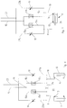
- Fig. 4 illustrates a simple embodiment of the hydraulic system of the hydraulic actuators 7,8 of the embodiments of the Fig. 1 to 3 ,
- the hydraulic system is connected, for example, to an inflow path 15, which is assigned jointly to the admission sides 13, 14, to a pressure source P and via a common outflow path 23 to a tank T (return flow).
- the inflow 15 includes a flow control valve 17, with the constant constant flow independent of pressure fluctuations upstream or downstream of the Beauftschungstress 13, 14 but also to the constantly open Ruströmweg 23 can be generated.
- the value of the volume flow can be adjustable, in adaptation to different operating or equipment conditions.
- the inflow path 15 branches at a junction 16 with inflow branch branches 15a, 15b to the lines 9, 10 to the admission sides 13, 14.
- the lines 9, 10 are further connected to Ragströmweg branches 23a, 23b, in each of which a control throttle 18 and 19 is arranged, which are adjustable via the control electronics CU, so that their throttle cross-section can optionally be changed continuously.
- hydraulic fluid circulates in the hydraulic system.
- the hydraulic medium circulates permanently with the set flow in the hydraulic system, wherein at the same setting control throttles 18, 19 due to the pressure differences generated by these same pressures on the Beauftschungshunt 13, 14 are constructed and the rod 1 is set parallel to the ground and is held as long as the sensors S do not provide different signals.
- the sensors S supply different signals, which indicate, for example, that the linkage 1 is lower on the side of the hydraulic actuator 7 than on the opposite side, then the throttling cross section of the control throttle 18 is reduced (possibly optionally) via the control electronics CU at the same time the throttle cross-section of the control throttle 19 increases), so that the Beaufschlagungsseite 13 receives higher pressure than the Beaufschlagungsseite 14 until the linkage 1 is set again in the ground-parallel pivot position.
- Rolling motions of the application vehicle F due to uneven ground occurring about the longitudinal axis are initially attenuated by hydraulic means, even using the inertia of the linkage 1, so that the ground-parallel position of the linkage 1 does not appreciably change.
- stagger in Fig. 1 the Ausbringhus F to the right, because the left wheels R pass over a survey, then the hydraulic actuator 7 is inserted and the hydraulic actuator 8 pulled out.
- the pressure at the admission side 13 increases and hydraulic fluid is expelled, of which a part flows through the control throttle 18 and attenuates and a part to the other hydraulic actuator 8 is displaced or causes the volume flow to the side of the hydraulic actuator 8 and the pressure on the admission side 14 rise briefly.
- the linkage 1 is essentially still kept parallel to the ground. At least a large part of the energy resulting from this rolling movement is consumed in the adjusting throttles 18, 19, which causes efficient damping. Nevertheless, should the linkage 1 develop the tendency to give up the ground-parallel pivotal position about the axis 4, an adjustment of at least one of the actuating throttles 18, 19 made on the control electronics CU based on the sensor signals to counteract this tendency or to eliminate them.
- the embodiment Fig. 5 is that the Fig. 2 similar.
- the hydraulic system of the two hydraulic actuators 7, 8 is different from that of the Fig. 4
- the common inflow path 15 which branches off at the junction 16 into the inflow branch branches 15a, 15b, contains a flow control valve 17a, 17b in each inflow branch 15a, 15b.
- a control throttle 18 is also arranged here, which is adjustable via the control electronics CU and lines 20.
- the sensors S on the linkage 1 are connected via a line 21 to the control electronics CU of the application vehicle F.
- a flow divider 22 indicated by dashed lines, the same constant in the two Zuströmweg branches 15a, 15b Volume flow sets.
- the hydraulic system upstream of the flow divider 22 may be designed so that the flow divider already receives a constant volume flow, which he divides, for example, in equal parts. In this way, separate flow control valves 17a, 17b can be saved.
- the admission sides 13, 14 are not directly connected to each other. Nevertheless, the ground-parallel pivoting position is easily adjusted and maintained and rolling movements of the application vehicle F are damped or compensated.
- the sensors provide identical values, there is a floor-parallel pivot position. If the value of the sensor S on the left side, for example, greater than the value of the sensor S on the right side, the control electronics CU reduces the throttle cross section of the control throttle 18 and increases the throttle cross section of the control throttle 19. Due to this change in the throttle cross sections, the pressure p1 increases on the loading side 13 against the decreasing pressure p2 on the loading side 14, whereby the pivoting position is returned to a floor-parallel pivoting position again. Since at the same time tunes the hydraulic medium via the control throttles 18, 19, is always attenuated.
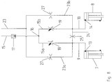
- Fig. 6 The embodiment in Fig. 6 is that the Fig. 5 similar.
- the Beauftschungstress 13, 14 and the lines 9, 10 connected via a cross-connection 24 with each other so that an exchange of hydraulic fluid at unequal pressures on the Beaufschlagungstrain 13, 14 is made possible.
- This can minimize the overall required hydraulic fluid flow rate and also prevents a rapid movement of a hydraulic actuator from pulling it to a vacuum.
- a fixed throttle 25 is contained in the connection 24, which is tuned in its passage cross-section to the respectively set volume flow or the passage cross section of the control throttle 18 or 19.
- the fixed throttle 25 could alternatively be adjustable, for example, be designed as a simple throttle screw.
- An exchange of hydraulic medium is similar, as based on Fig. 4 explained, however, the fixed throttle 25 can set significantly different pressures at the Beauftschungstrain 13, 14.
- Fig. 7 shows an embodiment of the hydraulic system similar to that of Fig. 5 ,
- the hydraulic actuator assembly 6 does not comprise two single-acting and counter-acting hydraulic actuators 7, 8, as in the following embodiments, but a single double-acting hydraulic actuator 26, with both Beaufschlagungslibrary 13, 14.
- the Hydraulic actuator 26 the hydraulic systems according to the Fig. 4 . 5 or 6 be combined.
- the flow control valve 17 is arranged, the permanent set constant flow, which divides into the Zuströmweg branches 15a, 15b.
- the inflow branch branches 15a, 15b each contain an actuating throttle 18, 19.
- the lines 9, 10 or admission sides 13, 14 are here connected via the cross-connection 24 for the exchange of hydraulic medium, preferably via the fixed throttle 25.
- the two Abströmweg branches 23a , 23b each contain a fixed throttle 27.
- the passage cross sections of the fixed throttle 27 may be equal to each other.
- the different pressures at the Beauftschungstress 13, 14 are generated here inter alia from the interaction of the respective control throttle 18 or 19 with its associated fixed throttle 27, wherein the constant volume flow from the flow control valve 17 differs differently, depending on the respective pressure efficiency on the control throttle 18 or 19. Also when damping the system, the control throttles 18 cooperate with the fixed throttles 27, possibly also with the fixed throttle 25.
- the hydraulic system of Fig. 8 can also for a double-acting hydraulic actuator 26 as in Fig. 7 be used.
- the flow control valve 17, 17a, 17b may be formed as a two-way flow control valve, or include a pressure compensator with associated throttle valve.
- This throttle valve could be adjusted by a proportional solenoid (possibly with hydraulic pilot control) in order to change the volume flow as needed.
- the control choke is expediently contained in a throttle valve with a proportional magnet, which can be controlled by the control electronics CU and adjusts the passage cross section proportionally to the current intensity or voltage.
- a transducer could provide feedback for the control electronics.
- a flow divider valve as in Fig. 5 arranged, this could be designed so that it not only divides the incoming flow in equal parts, but also keeps the flow rates constant.
- a steady flow or circulation of the hydraulic medium is generated via the admission sides.
- the pressure at the respective admission side can be varied by means of the adjusting throttles. For example, if the passage cross-section is reduced, the pressure at the Supply side until the amount of hydraulic fluid could flow over the reduced cross-section. This is effectively damped.
- the damping of the hydraulic system can be varied relatively easily. Namely, if the hydraulic actuators are adjusted due to relative movements between the linkage and the application vehicle, displaced hydraulic medium must be dissipated in addition to the permanently set volume flow through the respective outflow cross section.
- the total volume flow which must be dissipated via the discharge cross section, results from the constant volume flow in the inflow path and the temporarily displaced volume flow from the hydraulic actuator.
- the damping of the hydraulic system can be varied.
- the flow control valve for adjusting the individual pressure and at least one variable hydraulic flow supplying hydraulic pump can be used instead of the flow control valve for adjusting the individual pressure and at least one variable hydraulic flow supplying hydraulic pump.
- the hydraulic pump delivered and adjusted volume flow can be selected accordingly by means of suitable adjustment means.
Landscapes
- Life Sciences & Earth Sciences (AREA)
- Engineering & Computer Science (AREA)
- Insects & Arthropods (AREA)
- Pest Control & Pesticides (AREA)
- Wood Science & Technology (AREA)
- Zoology (AREA)
- Environmental Sciences (AREA)
- Vehicle Body Suspensions (AREA)
Description
- Die Erfindung betrifft ein Ausbringfahrzeug der im Oberbegriff des Patentanspruchs 1 angegebenen Art.
- Solche Ausbringfahrzeuge sind beispielsweise Feldspritzen oder Traktoren mit angebautem Gestänge zum Spritzen, wobei das Gestänge eine Arbeitsbreite von mehr als 20 Metern haben kann. Das Gestänge hat mittensymmetrische Ausleger, und trägt beispielsweise nach unten gerichtete Düsen zum Ausbringen eines Spritzmittels, wobei eine sich ändernde Distanz der Düsen zum Boden zu einer ungleichmäßigen Ausbringung führt. Bei solchen Ausbringfahrzeugen besteht deshalb die Notwendigkeit, das Gestänge in möglichst gleichbleibendem Abstand zum Boden zu führen. Wankbewegungen des Ausbringfahrzeugs um eine in Fahrzeugrichtung orientierte Längsachse sollen nicht, oder möglichst wenig, auf das Gestänge übertragen werden. Die weitestgehend bodenparallele Einstellung des Gestänges soll auch bei asymmetrischer Auskragung des Gestänges, beispielsweise bei einseitig eingeklappten Gestängeabschnitten erhalten bleiben.
- Bei dem aus
DE 10 200 702 5751 A1 bekannten Ausbringfahrzeug liegt der Schwerpunkt des Gestänges in etwa in der Achse, um welche das Gestänge relativ zum Ausbringfahrzeug, beispielsweise an dessen Rahmen, schwenkbar ist An den Enden des Gestänges ermitteln Sensoren den Abstand zum Boden. Die Sensoren sind mit der Steuerelektronik verbunden, die die Hydraulik-Aktuatoren-Anordnung so ansteuert, dass eine zumindest annähernde bodenparallele Schwenklage des Gestänges erreichbar ist. Bei durch einseitige Bodenunebenheiten verursachten Wankbewegungen des Ausbringfahrzeuges, um eine in Fahrtrichtung liegende virtuelle Achse,.wird das Gestänge im Schwerpunkt unzweckmäßig und gegebenenfalls rasch seitlich versetzt. Die Hydraulik-Aktuatoren-Anordnung wird so angesteuert, dass aus Wankbewegungen des Ausbringfahrzeugs über die Druckquelle über das Hydraulikventil an der druckbeaufschlagten Beaufschlagungsseite nahezu inkompressible Hydraulikmediumsäule resultierende Momente, die das Gestänge aus der bodenparallelen Lage zu bringen suchen, kompensiert werden. Dies erfordert hohen steuerungstechnischen Aufwand und einen schnellen Regeleingriff. - Bei der Ausbringmaschine gem.
EP 2 591 657 A1 wird eine noch hochwertigere Steuerungselektronik eingesetzt, um unter anderem Wankbewegungen des Ausbringfahrzeugs über Sensoren abzugreifen und die Hydraulik-Aktuatoren-Anordnung sogar im Wesentlichen in Echtzeit entsprechend nachzuführen. Diese aufwendige Steuerelektronik und die Sensorik sind teuer und aufgrund der Komplexität fehleranfällig. Außerdem erfolgen praktisch permanent Nachführbewegungen, damit die Hydraulik-Aktuatoren-Anordnung keine parasitären Kräfte oder Momente in das Gestänge übertragen kann. - Bei einem aus
FR 277 903 1A - Weiterer technologischer Hintergrund:
US 2007/289 298 A1 ,FR2 996 412 A1 - Der Erfindung liegt die Aufgabe zugrunde, ein Ausbringfahrzeug der eingangs genannten Art dahingehend zu verbessern, dass eine bodenparallele Schwenklage des Gestänges leichter einstellbar und haltbar ist, und mit geringem steuerungstechnischen Aufwand Wankbewegungen des Ausbringfahrzeugs vom Gestänge ferngehalten oder effizient gedämpft werden.
- Die gestellte Aufgabe wird mit den Merkmalen des Patentanspruchs 1 gelöst.
- Da das zumindest eine einstellbare Hydraulikelement einen permanenten konstanten Volumenstrom einstellt, und aus diesem Volumenstrom mit den im Durchgangs-Querschnitt verstellbaren Elementen die individuellen Drücke an den Beaufschlagungsseiten eingestellt werden, wobei eine permanente Zirkulation stattfindet, liegt keine eingespannte inkompressible Hydraulikmediumsäule vor, die die bodenparallele Schwenklage aufheben oder Wankbewegungen des Ausbringfahrzeugs im Wesentlichen ungedämpft auf das Gestänge übertragen könnte, sondern liegt eine Art nachgebende Schwimmstellung mit permanenter Zu- und Abströmung zu und von den Beaufschlagungsseiten vor.
- In einer Ausführungsform stellt das zumindest eine Stromregelventil den permanenten und konstanten Volumenstrom ein, und werden aus diesem Volumenstrom über die Stelldrosseln die individuellen Drücke an den Beaufschlagungsseiten eingestellt. Die Stelldrosseln ermöglichen es mit steuerungstechnisch geringem Aufwand, falls nötig, dennoch an den Beaufschlagungsseiten individuelle Drücke zu erzeugen. Die Verstelldrosseln erlauben nicht nur die individuelle Druckeinstellung, sondern erzeugen auch eine sehr wirksame Abdämpfung von Kräften oder Momenten, indem sie über die jeweils an ihnen wirksame Druckdifferenz Energie aus dem Hydraulikmedium aufzehren. Die Verstellung der Stelldrosseln über die Steuerelektronik erfolgt beispielsweise in Abhängigkeit von der Gleichheit oder Ungleichheit zwischen den Sensorsignalen, und wirkt sich im System mit einer wählbaren, aber relativ geringen Verzögerung aus. Die jeweilige Dämpfung beziehungsweise das Ansprechverhalten lassen sich bequem durch Abstimmen des eingestellten Volumenstroms und der Stelldrosseln an die gegebenen Anforderungen anpassen.
- Eine einfache Einstellung des Volumenstroms lässt sich auch mittels zumindest einer einen veränderbaren Hydraulikstrom liefernden Hydraulikpumpe erreichen.
- Zweckmäßig ist der Wert des mit dem wenigstens einen Stromregelventil oder der Hydraulikpumpe eingestellten Volumenstroms wählbar, beispielsweise über die Steuerelektronik, oder an einer Einstellvorrichtung oder direkt am Stromregelventil. Das Stromregelventil erzeugt den gewünschten konstanten Volumenstrom unabhängig von Druckschwankungen stromauf- und stromab und auch bei fluktuierender Viskosität des Hydraulik-Mediums.
- Zweckmäßig ist die Hydraulik-Aktuator-Anordnung entweder ein doppelt wirkender Hydraulik-Aktuator mit den ersten und zweiten Beaufschlagungsseiten, beispielsweise ein doppelt wirkender Hydraulikzylinder oder ein umsteuerbarer Hydraulikmotor, oder es sind zwei einfach wirkende, gegensinnig angreifende Hydraulik-Aktuatoren mit je einer Beaufschlagungsseite vorgesehen.
- Bei einer bevorzugten Lösung sind die Beaufschlagungsseiten miteinander quer verbunden, sodass das Hydraulikmedium, das an einer Beaufschlagungsseite verdrängt wird, an der anderen Beaufschlagungsseite eingespeist werden kann. Dies erfolgt zweckmäßig über eine Verbindungsleitung, in der vorzugsweise eine Drossel enthalten ist, um den Austausch zwischen den Beaufschlagungsseiten zu beeinflussen. Die Drossel kann eine Festdrossel sein, oder eine Stelldrossel, beispielsweise eine manuell oder elektromagnetisch verstellbare Stelldrossel. Diese Drossel beeinflusst auch das Dämpfungsverhalten wünschenswert und trägt dazu bei, den Verbrauch an Hydraulikmedium zu minimieren und zu vermeiden, dass die Hydraulik-Aktuatoren-Anordnung bei abrupten Bewegungen Vakuum ziehen könnte.
- Zweckmäßig ist ferner der Schwerpunkt des Gestänges im Abstand unterhalb der Achse angeordnet, sodass aus Wankbewegungen des Ausbringfahrzeuges resultierende Querbewegungen nicht unmittelbar in das Gestänge übertragen werden, da bei der gegebenen Trägheit des Gestänges nach Art eines Pendels ein zusätzlicher Freiheitsgrad um die Achse vorliegt. Dies schließt nicht aus, die Achse in etwa im Schwerpunkt des Gestänges zu platzieren.
- In einer zweckmäßigen Ausführungsform sind in einem sich zu den Beaufschlagungsseiten aufzweigenden, diesen gemeinsamen Zuströmweg stromauf der Aufzweigung ein Stromregelventil und in getrennten Abströmwegen von den Beaufschlagungsseiten je eine Verstelldrossel angeordnet. Diese Ausführungsform ist baulich und steuerungstechnisch einfach. Aufgrund der direkten Verbindung der Beaufschlagungsseiten lassen sich zwar keine extremen Druckunterschiede zwischen den Beaufschlagungsseiten realisieren, für die meisten Anwendungsfälle jedoch unterschiedliche Drücke, die ausreichend sind.
- Bei einer anderen Ausführungsform sind in einem sich zu dem Beaufschlagungsseiten aufzweigenden, diesen gemeinsamen Zuströmweg stromab der Aufzweigung in beiden Zuströmweg-Zweigen je ein Stromregelventil und in getrennten Abströmwegen von den Beaufschlagungsseiten je eine Stelldrossel angeordnet. Diese Ausführungsform ermöglicht es, den Druck an jeder Beaufschlagungsseite individuell und unabhängig vom Druck an der anderen Beaufschlagungsseite einzustellen.
- Bei einer weiteren Ausführungsform wird anstelle der beiden Stromregelventile an der Aufzweigung des Zuströmwegs ein Stromteilerventil eingesetzt, das in jedem Zuströmweg-Zweig einen konstanten Volumenstrom einstellt. Die Volumenströme können gleich sein. Es sind auch Stromteilerventile einsetzbar, deren Teilungsverhältnis sich variieren lässt.
- Bei den vorher erwähnten Ausführungsformen erfolgt die Druckeinstellung und die Dämpfung jeweils bei konstantem Zustrom und variablem Abstrom. Bei einer weiteren Ausführungsform wird hingegen mit variablem Zustrom und weitgehend konstantem Abstrom gearbeitet, in dem in einem sich zu den Beaufschlagungsseiten aufzweigenden, diesen gemeinsamen Zuströmweg stromauf der Aufzweigung ein Stromregelventil und in beiden Zuströmweg-Zweigen je eine Stelldrossel sowie in getrennten Abströmwegen von den Beaufschlagungsseiten je eine Festdrossel angeordnet sind. Diese Ausführungsvariante wird zweckmäßig kombiniert mit einer Verbindung zwischen den Beaufschlagungsseiten, in der eine Festdrossel oder konstante Blende angeordnet ist, sodass Hydraulikmedium zwischen den Beaufschlagungsseiten ausgetauscht werden kann. Für die Druckeinstellung und die Dämpfung wirken die Stelldrosseln und die Festdrosseln wechselseitig zusammen.
- Zweckmäßig ist zumindest die Stelldrossel in einem magnetbetätigten Ventil angeordnet, dessen Magnet von der Steuerelektronik ansteuerbar ist. Vorzugsweise wird hier sogar ein Proportionalmagnet eingesetzt, dessen Magnetkraft dem zugeführten Strom bzw. der Spannung proportional ist, sodass der Drosselquerschnitt der Stelldrossel stufenlos verändert wird. Dieses magnetbetätigte Ventil wird beispielsweise mit hydraulischer Vorsteuerung betrieben, um mit einem klein bauenden und relativ schwachen Magneten auszukommen. Ferner kann in der Aktorik des Ventils beispielsweise eine Wegaufnehmervorrichtung vorgesehen sein, um der Steuerelektronik eine Rückmeldung für eine ordnungsgemäße Verstellung zu liefern. Alternativ kann ein anderer Antrieb zur Verstellung der Stelldrossel verwendet werden.
- Ferner ist zweckmäßig das Stromregelventil beispielsweise ein Zweiwege-Stromregler und/oder kombiniert aus einer Druckwaage und einem Drosselventil in Sitzventil- oder Schieberventil-Bauweise. Vorzugsweise kann eine manuelle oder hydraulische oder magnetische Einstellvorrichtung für den Volumenstrom vorgesehen sein.
- Schließlich kann es zweckmäßig sein, wenn die Steuerelektronik mindestens einstellbar oder programmiert ist für Betriebsmodi, für horizontales Gelände, für Hanglagen und für eine asymmetrische Gestängeauskragung. Im Betriebsmodus für horizontales Gelände können die beiden Stelldrosseln gleich eingestellt sein, um an beiden Beaufschlagungsseiten gleiche Drücke einzustellen und bei Wankbewegungen des Ausbringfahrzeugs aufgrund unebenen Bodens effizient zu dämpfen. Im Betriebsmodus für eine Hanglage können beispielsweise abhängig vom Hangwinkel die beiden Stelldrosseln entsprechend unterschiedlich eingestellt sein, z.B. unter Berücksichtigung des unterhalb der Achse liegenden Schwerpunkts, wodurch das Gestänge nach Art eines Pendels um die Achse ausgelenkt werden könnte, was durch die unterschiedlichen Drücke vermieden wird. Ähnlich wird im Betriebsmodus für asymmetrische Gestängeauskragung abhängig von der Größe der Asymmetrie von vornherein ein Unterschied zwischen den Einstellungen der Stelldrosseln gewählt.
- Ausführungsformen des Erfindungsgegenstandes werden anhand der Zeichnung erläutert. Es zeigen:
- Fig. 1:
- eine Schemaansicht eines Ausbringfahrzeugs in Fahrtrichtung,
- Fig. 2:
- eine Ansicht ähnlich der von
Fig. 1 einer weiteren Ausführungsform, - Fig. 3:
- eine Ansicht ähnlich der von
Fig. 1 einer weiteren Ausführungsform, - Fig. 4:
- ein Blockschaltbild eines Hydrauliksystems,
- Fig. 5:
- eine Schemadarstellung einer weiteren Ausführungsform eines Ausbringfahrzeugs ähnlich der
Fig. 2 mit einem Blockschaltbild eines Hydrauliksystems, - Fig. 6:
- ein Blockschaltbild einer weiteren Ausführungsform eines Hydrauliksystems,
- Fig. 7:
- ein Blockschaltbild einer noch weiteren Ausführungsform eines Hydrauliksystems, ähnlich dem von
Fig. 5 , jedoch mit einem doppelt wirkenden Hydraulik-Aktuator, - Fig. 8:
- ein Blockschaltbild einer noch weiteren Ausführungsform eines Hydrauliksystems.
-
Fig. 1 ist eine schematische Hinter- oder Vorderansicht eines Ausbringfahrzeugs F, z.B. einer Feldspritze mit einem quer zur Fahrtrichtung (in der Zeichnungsebene) orientierten, im Regelfall symmetrisch beidseitig weit von einem Rahmen 5 auskragenden Gestänge 1, von welchem ein Mittelteil 2 und daran beispielsweise klappbar angeordnete Auslegerteile 3 angedeutet sind. Das Ausbringfahrzeug F kann selbstfahrend ausgelegt sein (z. B. auf Rädern R), oder wird geschleppt oder gezogen. Alternativ könnte das Gestänge 1 an einen Traktor angebaut sein. - Das Ausbringfahrzeug F hat den gegebenenfalls in seiner Höhenlage einstellbaren Rahmen 5, an welchem das Gestänge 1, z. B. mit dem Rahmen 5, um eine im Wesentlichen in Fahrtrichtung orientierte Achse 4 schwenkbar ist. Dabei kann, optional, der Schwerpunkt G des Gestänges 1 im Abstand unterhalb der Achse 4 liegen.
- Beim Ausbringen soll das Gestänge 1 eine Schwenklage um die Achse 4 einnehmen, in der es zumindest im Wesentlichen bodenparallel orientiert ist. Das gilt auch für das Ausbringen in einer seitlich geneigten Hanglage oder bei asymmetrischer Auskragung des Gestänges, beispielsweise weil an einer Seite ein oder mehrere Auslegerabschnitte 3 eingeklappt ist bzw. sind.
- Zum Einstellen der Schwenklage und zum Halten der Schwenklage des Gestänges 1 ist eine Hydraulik-Aktuator-Anordnung 6 zwischen dem Ausbringfahrzeug F, beziehungsweise dessen Rahmen 5, und dem Gestänge 1 vorgesehen. Die Hydraulik-Akuator-Anordnung 6 in
Fig. 1 umfasst zwei einseitig an einer Beaufschlagungsseite 13, 14 mit hydraulischem Druck beaufschlagbare gegenseitig arbeitende Hydraulik-Aktuatoren 7, 8 typischerweise HydraulikZylinder. Alternativ könnten auch ein drehrichtungsumkehrbarer Hydraulikmotor zwei mit gegensinnigen Drehrichtungen antreibbare Hydraulikmotoren eingesetzt werden. - Der Hydraulik-Aktuator 7 ist am Rahmen 5 in einer Anlenkung 11 und am Gestänge 1 bzw. dessen Mittelteil 2 in einer Anlenkung 12 jeweils schwenkbar abgestützt, wobei die Anlenkung 12 weiter außen liegt als die Anlenkung 11, und die Anlenkungen 11, 12 in etwa den gleichen Radialabstand von der Achse 4 haben. Der Hydraulik-Aktuator 8 ist spiegelbildlich in Anlenkungen 11', 12' abgestützt. Die Beaufschlagungsseiten 13, 14 sind jeweils über eine Leitung 9, 10 mit einem nicht dargestellten Hydrauliksystem verbunden. Zumindest am Gestänge 1 sind Sensoren S vorgesehen, z.B. Abstandssensoren, die mit einer Steuerelektronik CU signalübertragend verbunden sind. Die Sensorik kann weitere Sensoren am Ausbringfahrzeug F und/oder Gestänge 1 umfassen, z.B. Neigungssensoren und dergleichen. Die Steuerelektronik CU ist auch zumindest mit dem Hydrauliksystem der Hydraulik-Aktuatoren-Anordnung 6 verbunden.
- Zweck der Hydraulik-Aktuatoren-Anordnung 6 ist es, das Gestänge 1 unter unterschiedlichen Betriebskonditionen zumindest im Wesentlichen bodenparallel zu halten und auch unter Nutzen der Trägheit des weitauskragenden Gestänges 1 bei Wankbewegungen des Ausbringfahrzeugs F auf unebenem Boden deren Einfluss auf die Schwenklage des Gestänges effizient zu dämpfen oder zu kompensieren.
- Die Ausführungsform der
Fig. 2 unterscheidet sich von der derFig. 1 hauptsächlich dadurch, dass die Hydraulik-Aktuatoren-Anordnung 6 anders gestaltet ist, und zwar mit zwei einseitig beaufschlagbaren Hydraulik-Aktuatoren 7, 8, die am Gestänge 1 bzw. dessen Mittelteil 2 in einer gemeinsamen Anlenkung 12 abgestützt sind, während ihre Anlenkungen 11, 11' in etwa zwischen dem Schwerpunkt G und der Achse 4 am Rahmen 5 platziert sind. - In der Ausführungsform der
Fig. 3 sind die beiden einseitig beaufschlagbaren Hydraulik-Aktuatoren 7, 8 in etwa horizontal angeordnet, am Gestänge 1 bzw. dessen Mittelteil 12 z. B. oberhalb des Schwerpunkts G und der Achse 4 in der gemeinsamen Anlenkung 12 abgestützt, hingegen am Rahmen 5 an außenliegenden Anlenkungen 11, 11'. Der Schwerpunkt G des Gestänges 1 liegt hier z. B. zumindest im Wesentlichen in der Achse 4. -
Fig. 4 verdeutlicht eine einfache Ausführungsform des Hydrauliksystems der bei den Hydraulik-Aktuatoren 7,8 der Ausführungsformen derFig. 1 bis 3 . Das Hydrauliksystem ist beispielsweise mit einem den Beaufschlagungsseiten 13,14 gemeinsam zugeordneten Zuströmweg 15 an eine Druckquelle P und über einen gemeinsamen Abströmweg 23 an einen Tank T (Rücklauf) angeschlossen. Der Zuströmweg 15 enthält ein Stromregelventil 17, mit dem permanent ein konstanter Volumenstrom unabhängig von Druckschwankungen stromauf- oder stromab zu den Beaufschlagungsseiten 13, 14 aber auch zum ständig offenen Rückströmweg 23 erzeugbar ist. Der Wert des Volumenstroms kann einstellbar sein, in Anpassung an unterschiedliche Betriebs- bzw. Ausstattungsbedingungen. Der Zuströmweg 15 zweigt an einer Aufzweigung 16 mit Zuströmweg-Zweigen 15a, 15b zu den Leitungen 9, 10 zu den Beaufschlagungsseiten 13, 14 auf. Die Leitungen 9, 10 sind ferner mit Rückströmweg-Zweigen 23a, 23b verbunden, in welchen jeweils eine Stelldrossel 18 bzw. 19 angeordnet ist, die über die Steuerelektronik CU einstellbar sind, sodass sich ihr Drosselquerschnitt optional stufenlos verändern lässt. In jedem Betriebsmodus zirkuliert Hydraulikmedium im Hydrauliksystem. - Im Betriebsmodus auf horizontalem Gelände zirkuliert das Hydraulikmedium permanent mit dem eingestellten Volumenstrom im Hydrauliksystem, wobei bei gleich eingestellten Stelldrosseln 18, 19 aufgrund der von diesen erzeugten Druckdifferenzen gleiche Drücke an den Beaufschlagungsseiten 13, 14 aufgebaut werden und das Gestänge 1 bodenparallel eingestellt ist und gehalten wird, solange die Sensoren S keine unterschiedlichen Signale liefern. Liefern die Sensoren S unterschiedliche Signale, die beispielsweise anzeigen, dass das Gestänge 1 an der Seite des Hydraulik-Aktuators 7 tiefer steht als an der gegenüberliegenden Seite, dann wird über die Steuerelektronik CU der Drosselquerschnitt der Stelldrossel 18 verkleinert (gegebenenfalls optional gleichzeitig der Drosselquerschnitt der Stelldrossel 19 vergrößert), so dass die Beaufschlagungsseite 13 höheren Druck erhält als die Beaufschlagungsseite 14, bis das Gestänge 1 wieder in die bodenparallele Schwenklage eingestellt wird.
- Um die Längsachse auftretende Wankbewegungen des Ausbringfahrzeugs F aufgrund unebenen Bodens werden zunächst auf hydraulischem Weg abgedämpft, auch unter Nutzung der Trägheit des Gestänges 1, so dass sich die bodenparallele Lage des Gestänges 1 nicht nennenswert ändert. Wankt beispielsweise in
Fig. 1 das Ausbringfahrzeug F nach rechts, weil die linken Räder R eine Erhebung überfahren, dann wird der Hydraulik-Aktuator 7 eingeschoben und der Hydraulik-Aktuator 8 ausgezogen. Beim Einschieben des Hydraulik-Aktuators 7 steigt der Druck an der Beaufschlagungsseite 13 an und wird Hydraulikmedium ausgeschoben, von dem ein Teil durch die Stelldrossel 18 abströmt und dämpft und ein Teil zum anderen Hydraulik-Aktuator 8 verlagert wird bzw. bewirkt, dass der Volumenstrom an der Seite des Hydraulik-Aktuators 8 und der Druck an der Beaufschlagungsseite 14 kurzzeitig steigen. Im Resultat wird das Gestänge 1 im Wesentlichen weiterhin bodenparallel gehalten. Zumindest ein Großteil der aus dieser Wankbewegung resultierenden Energie wird in den Stelldrosseln 18, 19 aufgezehrt, was eine effiziente Dämpfung bewirkt. Sollte dennoch das Gestänge 1 die Tendenz entwickeln, die bodenparallele Schwenklage um die Achse 4 aufzugeben, wird über die Steuerelektronik CU anhand der Sensorsignale eine Verstellung zumindest einer der Stelldrosseln 18, 19 vorgenommen, um dieser Tendenz entgegenzuwirken bzw. sie zu beseitigen. - Die Ausführungsform
Fig. 5 ist der derFig. 2 ähnlich. Das Hydrauliksystem der beiden Hydraulik-Aktuatoren 7, 8 ist insofern unterschiedlich von dem derFig. 4 , als der gemeinsame Zuströmweg 15, der an der Aufzweigung 16 in die Zuströmweg-Zweige 15a, 15b aufzweigt, in jedem Zuströmweg-Zweig 15a, 15b ein Stromregelventil 17a, 17b enthält. In den Abströmweg-Zweigen 23a, 23b ist auch hier jeweils eine Stelldrossel 18 angeordnet, die über die Steuerelektronik CU und Leitungen 20 verstellbar ist. Die Sensoren S am Gestänge 1 sind über eine Leitung 21 mit der Steuerelektronik CU des Ausbringfahrzeugs F verbunden. - Als Alternative ist in
Fig. 5 an der Aufzweigung 16 ein Stromteiler 22 gestrichelt angedeutet, der in den beiden Zuströmweg-Zweigen 15a, 15b gleiche konstante Volumenströme einstellt. Hier kann stromauf des Stromteilers 22 die Hydraulik so ausgelegt sein, dass der Stromteiler bereits einen konstanten Volumenstrom erhält, den er beispielsweise zu gleichen Teilen aufteilt. Auf diese Weise können separate Stromregelventile 17a, 17b eingespart werden. - In der Ausführungsform in
Fig. 5 sind die Beaufschlagungsseiten 13, 14 nicht direkt miteinander verbunden. Dennoch wird die bodenparallele Schwenklage leicht eingestellt und gehalten und werden Wankbewegungen des Ausbringfahrzeugs F abgedämpft bzw. kompensiert. Wenn die Sensoren identische Werte liefern, liegt eine bodenparallele Schwenklage vor. Ist der Wert des Sensors S an der linken Seite beispielsweise größer als der Wert des Sensors S an der rechten Seite, verringert die Steuerelektronik CU den Drosselquerschnitt der Stelldrossel 18 und vergrößert den Drosselquerschnitt der Stelldrossel 19. Aufgrund dieser Veränderung der Drosselquerschnitte erhöht sich der Druck p1 an der Beaufschlagungsseite 13 gegenüber dem sich verringernden Druck p2 an der Beaufschlagungsseite 14, wodurch die Schwenklage wieder in eine bodenparallele Schwenklage zurückgeführt wird. Da gleichzeitig Hydraulikmedium über die Stelldrosseln 18, 19 abstimmt, wird stets gedämpft. - Ist das Gestänge 1 so eingestellt, dass es asymmetrisch auskragt, würde es aufgrund der Schwerkraft in
Figur 1 pendelartig um die Achse 4 kippen. Eine solche Tendenz wird von den Sensoren S festgestellt, worauf die Steuerelektronik CU die Stelldrosseln 18, 19 entsprechend umstellt, bis sich trotz der Asymmetrie das Gestänge wieder in der bodenparallelen Schwenklage befindet. - Es kann die Steuerelektronik alternativ oder additiv vorprogrammiert oder eingestellt werden, dass dieser Betriebsmodus automatisch ausgeführt wird, z. B. während des Aus- oder Einklappens von Ausleger-Abschnitten 3.
- Wankt das Ausbringfahrzeug F in
Fig. 5 nach rechts, wird der Hydraulik-Aktuator 7 ausgezogen und wird der Hydraulik-Aktuator 8 eingeschoben. Da der Druck p1 sinkt, sinkt auch die Druckdifferenz über die Stelldrossel 18, und geht relativ mehr Hydraulikmedium durch die dämpfende Stelldrossel 18 durch. Am anderen Hydraulik-Aktuator 8 steigt der Druck p2 und die Druckdifferenz über die Stelldrossel 19 die und noch stärker dämpft. Sollte es dabei zur Aufgabe der bodenparallelen Schwenklage des Gestänges 1 kommen, greift die Steuerelektronik CU ein, um durch Veränderung der Drosselquerschnitte der Stelldrosseln 18 und 19 oder nur 18 oder 19 die Drücke p1, p2 weiter zu ändern und so die bodenparallele Schwenklage wieder einzustellen. - Die Ausführungsform in
Fig. 6 ist der derFig. 5 ähnlich. Im Unterschied zuFig. 5 sind jedoch die Beaufschlagungsseiten 13, 14 bzw. die Leitungen 9, 10 über eine Querverbindung 24 miteinander verbunden, so dass ein Austausch an Hydraulikmedium bei ungleichen Drücken an den Beaufschlagungsseiten 13, 14 ermöglicht wird. Dies kann den insgesamt erforderlichen Durchsatz an Hydraulikmedium minimieren lassen, und verhindert auch, dass bei einer schnellen Bewegung eines Hydraulik-Aktuators dieser ein Vakuum ziehen könnte. Zweckmäßig ist in der Verbindung 24 eine Festdrossel 25 enthalten, die in ihrem Durchgangsquerschnitt auf den jeweils eingestellten Volumenstrom bzw. den Durchgangsquerschnitt der Stelldrossel 18 oder 19 abgestimmt ist. Die Festdrossel 25 könnte alternativ auch verstellbar sein, z.B. als einfache Drosselschraube ausgebildet werden. Ein Austausch an Hydraulikmedium läuft ähnlich ab, wie anhandFig. 4 erläutert, allerdings lässt die Festdrossel 25 deutlich unterschiedliche Drücke an den Beaufschlagungsseiten 13, 14 einstellen. -
Fig. 7 zeigt eine Ausführungsform des Hydrauliksystems ähnlich der vonFig. 5 . Im Unterschied umfasst hier die Hydraulik-Aktuator-Anordnung 6 nicht zwei einfach wirkende und gegensinnig angreifende Hydraulik-Aktuatoren 7, 8, wie in den hervorgehenden Ausführungsformen, sondern einen einzigen doppelt wirkenden Hydraulik-Aktuator 26, mit beiden Beaufschlagungsseiten 13, 14. Mit dem Hydraulik-Aktuator 26 können die Hydrauliksysteme entsprechend denFig. 4 ,5 oder6 kombiniert werden. - In den Ausführungsformen der
Fig. 4 ,5 ,6 und 7 wird mit einem Prinzip gearbeitet, bei dem eine konstante Zuströmung und eine variable Abströmung realisiert sind, während in der nachfolgenden Ausführungsform derFig. 8 eine variable Zuströmung und eine konstante Abströmung realisiert sind. - In der Ausführungsform der
Fig. 8 ist im Zuströmweg 15 stromauf der Aufzweigung 16 das Stromregelventil 17 angeordnet, das permanent den konstanten Volumenstrom einstellt, der sich in die Zuströmweg-Zweige 15a, 15b aufteilt. Die Zuströmweg-Zweige 15a, 15b enthalten jeweils eine Stelldrossel 18, 19. Die Leitungen 9, 10 bzw. Beaufschlagungsseiten 13, 14 sind hier über die Querverbindung 24 zum Austausch von Hydraulikmedium verbunden, bevorzugt über die Festdrossel 25. Die beiden Abströmweg-Zweige 23a, 23b enthalten jeweils eine Festdrossel 27. Die Durchgangsquerschnitte der Festdrosseln 27 können untereinander gleich sein. Die unterschiedlichen Drücke an den Beaufschlagungsseiten 13, 14 werden hier unter anderem aus dem Zusammenspiel der jeweiligen Stelldrossel 18 oder 19 mit der ihr zugeordneten Festdrossel 27 erzeugt, wobei sich der konstante Volumenstrom aus dem Stromregelventil 17 unterschiedlich aufteilt, abhängig von der jeweiligen Druckeffizienz über die Stelldrossel 18 oder 19. Auch beim Dämpfen des Systems wirken die Stelldrosseln 18 mit den Festdrosseln 27 zusammen, gegebenenfalls auch mit der Festdrossel 25. Das Hydrauliksystem derFig. 8 kann auch für einen doppelseitig beaufschlagbaren Hydraulik-Aktuator 26 wie inFig. 7 verwendet werden. - Das Stromregelventil 17, 17a, 17b kann als Zweiwege-Stromreglerventil ausgebildet sein, oder eine Druckwaage mit zugeordnetem Drosselventil umfassen. Dieses Drosselventil könnte durch einen Proportialmagneten (gegebenenfalls mit hydraulischer Vorsteuerung) verstellbar sein, um den Volumenstrom nach Bedarf ändern zu können. Die Stelldrossel ist zweckmäßig in einem Drosselventil mit einem Proportialmagneten enthalten, der von der Steuerelektronik CU ansteuerbar ist und den Durchgangsquerschnitt proportional zur Stromstärke oder Spannung einstellt. Hier könnte ein Wegaufnehmer eine Rückmeldung für die Steuerelektronik bereitstellen. Im Falle eines Stromteilerventils, wie in
Fig. 5 angeordnet, könnte dieses so ausgelegt sein, dass es nicht nur den ankommenden Volumenstrom in gleiche Teile aufteilt, sondern die Volumenströme auch konstant hält. - Grundsätzlich wird zum Einstellen und/oder Variieren der Drücke an den Beaufschlagungsseiten 13, 14 ein stetiger Fluss oder Umlauf des Hydraulikmediums über die Beaufschlagungsseiten erzeugt. Der Druck an der jeweiligen Beaufschlagungsseite kann mittels der Stelldrosseln variiert werden. Wird beispielsweise der Durchgangsquerschnitt verringert, steigt der Druck an der Beaufschlagungsseite solange an, bis die Hydraulikmediummenge über den verringerten Querschnitt abfließen konnte. Dabei wird wirksam gedämpft. Die Dämpfung des Hydrauliksystems lässt sich relativ einfach variieren. Wenn nämlich die Hydraulik-Aktuatoren aufgrund von Relativbewegungen zwischen dem Gestänge und dem Ausbringfahrzeug verstellt werden, muss verdrängtes Hydraulikmedium zusätzlich zum permanent eingestellten Volumenstrom über den jeweiligen Abströmquerschnitt abgeführt werden. Der gesamte Volumenstrom, der über den Abflussquerschnitt abgeführt werden muss, ergibt sich aus dem konstanten Volumenstrom im Zuströmweg und dem zeitweilig verdrängten Volumenstrom aus dem Hydraulik-Aktuator. Durch Ändern des Verhältnisses zwischen dem konstant eingestellten Volumenstrom und dem aus dem Hydraulik-Aktuator verdrängten Volumenstrom lässt sich die Dämpfung des Hydrauliksystems variieren.
- In einem nicht dargestellten Ausführungsbeispiel kann anstelle des Stromregelventils zur Einstellung des individuellen Druckes auch zumindest eine einen veränderbaren Hydraulikstrom liefernde Hydraulikpumpe eingesetzt werden. Hierbei ist der Hydraulikpumpe gelieferte und einzustellende Volumenstrom entsprechend mittels geeigneter Einstellmittel wählbar.
Claims (14)
- Ausbringfahrzeug (F) mit einem zumindest um eine in etwa in Fahrtrichtung orientierte Achse (4), schwenkbaren, quer zur Fahrtrichtung orientierten Gestänge (1) und einer wirkungsmäßig zwischen dem Ausbringfahrzeug (F) und dem Gestänge (1) angeordneten Hydraulik-Aktuator-Anordnung (6) zum Einstellen und Halten einer zumindest im Wesentlichen bodenparallelen Schwenklage des mit mit einer Steuerelektronik (CU) verbundenen Sensoren (S) ausgestatteten Gestänges (1), wobei die Hydraulik-Aktuator-Anordnung (6) über eine Hydraulikeinrichtung an einer ersten und einer zweiten Beaufschlagungsseite (13, 14) über Strömungswege mit einem eine Druckquelle (P) und einen Tank (T) umfassenden Hydrauliksystem verbunden und an jeder Beaufschlagungsseite (13, 14) individuell mit Druck beaufschlagbar ist, dadurch gekennzeichnet, dass die Hydraulikeinrichtung wenigstens ein permanent einen konstanten Volumenstrom im Hydrauliksystem einstellendes Hydraulikelement (17, 17 a, 17 b, 22) ist, und dass in mit der Druckquelle (P) und dem Tank (T) verbundenen Strömungswegen zu und von den Beaufschlagungsseiten (13,14) jeder Beaufschlagungsseite (13, 14) ein zumindest über die Steuerelektronik (CU) im Durchgangsquerschnitt verstellbares Element (18, 19) zum individuellen Einstellen des Drucks zugeordnet ist.
- Ausbringfahrzeug nach Anspruch 1, dadurch gekennzeichnet, dass das Hydraulikelement (17, 17a, 17b, 22) ein Stromregelventil ist und dass das Element (18, 19) eine Stelldrossel ist.
- Ausbringfahrzeug nach Anspruch 1, dadurch gekennzeichnet, dass das Hydraulikelement (17, 17a, 17b, 22) eine einen veränderbaren Hydraulikstrom liefernde Hydraulikpumpe ist und dass das Element eine Stelldrossel ist.
- Ausbringfahrzeug nach Anspruch 1, dadurch gekennzeichnet, dass der Wert des vom Stromregelventil oder der Hydraulikpumpe eingestellten Volumenstroms wählbar ist.
- Ausbringfahrzeug nach Anspruch 1, dadurch gekennzeichnet, dass die Hydraulik-Akuator-Anordnung (6) entweder einen doppelt wirkenden Hydraulik-Aktuator (26) mit beiden Beaufschlagungszeiten (13, 14) oder zwei einfach wirkende gegensinnig angreifende Hydraulik-Aktuatoren (7, 8) mit jeweils einer der Beaufschlagungsseiten (13, 14) aufweist.
- Ausbringfahrzeug nach einem der vorhergehenden Ansprüche, dadurch gekennzeichnet, dass die ersten und zweiten Beaufschlagungsseiten (13, 14) miteinander quer verbunden sind, vorzugsweise über eine Festdrossel (25) oder eine Stelldrossel.
- Ausbringfahrzeug nach mindestens einem der vorhergehenden Ansprüche, dadurch gekennzeichnet, dass der Schwerpunkt (G) des Gestänges (1) im Abstand unterhalb der Achse (4) liegt.
- Ausbringfahrzeug nach wenigstens einem der vorhergehenden Ansprüche, dadurch gekennzeichnet, dass in einem sich zu den Beaufschlagungsseiten (13, 14) aufzweigenden, diesen gemeinsamen Zuströmweg (15) stromauf der Aufzweigung (16) ein Stromregelventil (17) und in getrennten Abströmwegen (23a, 23b) von beiden Beaufschlagungsseiten (13, 14) je eine Verstelldrossel (18, 19) angeordnet sind.
- Ausbringfahrzeug nach wenigstens einem der Ansprüche 1 bis 6, dadurch gekennzeichnet, dass in einem sich zu den Beaufschlagungsseiten (13, 14) aufzweigenden, diesen gemeinsamen Zuströmweg (15) stromab der Aufzweigung (16) in beiden Zuströmweg-Zweigen (15a, 15b) je ein Stromregelventil (17a, 17b) und in getrennten Abströmwegen (23a, 23b) von den Beaufschlagungsseiten (13, 14) je eine Stelldrossel (18, 19) angeordnet sind.
- Ausbringfahrzeug nach wenigstens einem der Ansprüche 1 bis 6, dadurch gekennzeichnet, dass in einem sich zu den Beaufschlagungsseiten (13, 14) aufzweigenden, diesen gemeinsamen Zuströmweg (15) an der Aufzweigung (16) ein Stromteilerventil (22) und in getrennten Abströmwegen (23a, 23b) von den Beaufschlagungsseiten (13, 14) je eine Stelldrossel (18, 19) angeordnet sind.
- Ausbringfahrzeug nach wenigstens einem der Ansprüche 1 bis 6, dadurch gekennzeichnet, dass in einem sich zu den Beaufschlagungsseiten (13, 14) aufzweigenden, diesen gemeinsamen Zuströmweg (15) stromauf der Aufzweigung (16) ein Stromregelventil (17) und in beiden Zuströmweg-Zweigen (15a, 15b) je eine Stelldrossel (18, 19) sowie in getrennten Abströmwegen (23a, 23b) von den Beaufschlagungsseiten (13, 14) je eine Festdrossel (27) angeordnet sind.
- Ausbringfahrzeug nach wenigstens einem der Ansprüche 8 bis 11, dadurch gekennzeichnet, dass zumindest die Stelldrossel (18, 19) in einem magnetbetätigten Ventil untergebracht ist, vorzugsweise in einem Ventil mit wenigstens einem von der Steuerelektronik (CU) ansteuerbaren Proportionalmagneten.
- Ausbringfahrzeug nach Anspruch 2, dadurch gekennzeichnet, dass das Stromregelventil (17, 17a, 17b) eine Druckwaage und ein Drosselventil umfasst, vorzugsweise mit manueller, hydraulischer oder magnetischer Einstellvorrichtung für den Volumenstrom.
- Ausbringfahrzeug nach wenigstens einem der vorhergehenden Ansprüche, dadurch gekennzeichnet, dass die Steuerelektronik (CU) mindestens einstellbar oder programmiert ist auf Betriebsmodi für horizontales Gelände, für Hanglagen, und für eine asymmetrische Gestänge-Auskragung.
Priority Applications (1)
| Application Number | Priority Date | Filing Date | Title |
|---|---|---|---|
| PL15401028T PL2932841T3 (pl) | 2014-04-16 | 2015-04-14 | Rozlewacz nawozów płynnych |
Applications Claiming Priority (1)
| Application Number | Priority Date | Filing Date | Title |
|---|---|---|---|
| DE102014105416.4A DE102014105416A1 (de) | 2014-04-16 | 2014-04-16 | Ausbringfahrzeug |
Publications (2)
| Publication Number | Publication Date |
|---|---|
| EP2932841A1 EP2932841A1 (de) | 2015-10-21 |
| EP2932841B1 true EP2932841B1 (de) | 2017-01-25 |
Family
ID=53181228
Family Applications (1)
| Application Number | Title | Priority Date | Filing Date |
|---|---|---|---|
| EP15401028.4A Not-in-force EP2932841B1 (de) | 2014-04-16 | 2015-04-14 | Ausbringfahrzeug |
Country Status (4)
| Country | Link |
|---|---|
| EP (1) | EP2932841B1 (de) |
| DE (1) | DE102014105416A1 (de) |
| DK (1) | DK2932841T3 (de) |
| PL (1) | PL2932841T3 (de) |
Cited By (3)
| Publication number | Priority date | Publication date | Assignee | Title |
|---|---|---|---|---|
| EP4245136A1 (de) * | 2022-03-15 | 2023-09-20 | Exel Industries SA | Pendelaufhängungsvorrichtung eines sprühauslegers und verfahren zur ausrichtung einer pendelaufhängungsvorrichtung eines sprühauslegers |
| US11980180B2 (en) | 2020-03-04 | 2024-05-14 | Deere & Company | Pendulum boom suspension |
| EP4477046A1 (de) * | 2023-06-15 | 2024-12-18 | HORSCH LEEB Application Systems GmbH | Tragstruktur für ein landwirtschaftliches arbeitsgerät zur ausbringung eines landwirtschaftlichen guts auf einem boden, arbeitsgerät mit einer tragstruktur und verfahren zum ausbringen eines landwirtschaftlichen guts |
Families Citing this family (1)
| Publication number | Priority date | Publication date | Assignee | Title |
|---|---|---|---|---|
| DE102016103864A1 (de) * | 2016-03-03 | 2017-09-07 | Inuma Fahrzeug-Service Und Maschinenbau Gmbh | Arretierungsvorrichtung, Laufwagenvorrichtung und Fahrzeug |
Family Cites Families (5)
| Publication number | Priority date | Publication date | Assignee | Title |
|---|---|---|---|---|
| FR2779031B1 (fr) | 1998-06-02 | 2004-12-03 | Exel Ind | Ensemble de rampe pendulaire, notamment pour engin de pulverisation agricole, equipe d'un dispositif de correction d'inclinaison |
| US7426827B2 (en) * | 2006-06-15 | 2008-09-23 | Cnh Canada, Ltd. | Suspension arrangement for a boom assembly mounted on an agricultural sprayer |
| DE102007025751B4 (de) | 2007-06-01 | 2022-08-25 | Amazonen-Werke H. Dreyer SE & Co. KG | Verteilmaschine |
| EP3219187B1 (de) | 2011-11-08 | 2023-10-04 | HORSCH LEEB Application Systems GmbH | Fahrbare vorrichtung zum ausbringen von flüssigen und/oder festen wirkstoffen und verfahren zur steuerung der vorrichtung |
| FR2996412B1 (fr) * | 2012-10-04 | 2014-12-19 | Gyrland Ind S A S | Dispositif de suspension de rampe de pulverisateur agricole |
-
2014
- 2014-04-16 DE DE102014105416.4A patent/DE102014105416A1/de not_active Withdrawn
-
2015
- 2015-04-14 DK DK15401028.4T patent/DK2932841T3/en active
- 2015-04-14 PL PL15401028T patent/PL2932841T3/pl unknown
- 2015-04-14 EP EP15401028.4A patent/EP2932841B1/de not_active Not-in-force
Non-Patent Citations (1)
| Title |
|---|
| None * |
Cited By (3)
| Publication number | Priority date | Publication date | Assignee | Title |
|---|---|---|---|---|
| US11980180B2 (en) | 2020-03-04 | 2024-05-14 | Deere & Company | Pendulum boom suspension |
| EP4245136A1 (de) * | 2022-03-15 | 2023-09-20 | Exel Industries SA | Pendelaufhängungsvorrichtung eines sprühauslegers und verfahren zur ausrichtung einer pendelaufhängungsvorrichtung eines sprühauslegers |
| EP4477046A1 (de) * | 2023-06-15 | 2024-12-18 | HORSCH LEEB Application Systems GmbH | Tragstruktur für ein landwirtschaftliches arbeitsgerät zur ausbringung eines landwirtschaftlichen guts auf einem boden, arbeitsgerät mit einer tragstruktur und verfahren zum ausbringen eines landwirtschaftlichen guts |
Also Published As
| Publication number | Publication date |
|---|---|
| DK2932841T3 (en) | 2017-05-08 |
| EP2932841A1 (de) | 2015-10-21 |
| DE102014105416A1 (de) | 2015-10-22 |
| PL2932841T3 (pl) | 2017-07-31 |
Similar Documents
| Publication | Publication Date | Title |
|---|---|---|
| EP3449723B1 (de) | Steuer- und/oder regelsystem, landwirtschaftliches nutzfahrzeug und verfahren zur steuerung und/oder regelung | |
| EP3629725B1 (de) | Steuereinrichtung für eine ausbringvorrichtung und ausbringvorrichtung mit einer steuereinrichtung | |
| EP3753407B1 (de) | Landwirtschaftliches gerät mit verbesserter neigungsregelung | |
| EP3468340B1 (de) | Regelvorrichtung, landwirtschaftliches nutzfahrzeug und verfahren zum betreiben eines landwirtschaftlichen nutzfahrzeuges | |
| DE102007047886A1 (de) | Spritzengestänge | |
| EP3075246B1 (de) | Landwirtschaftliche maschine und sicherheitsverfahren | |
| EP2932841B1 (de) | Ausbringfahrzeug | |
| WO2021037517A1 (de) | Landwirtschaftliches gerät mit verbesserter aufhängung | |
| EP3592143B1 (de) | Steuer- und/oder regelsystem, landwirtschaftliches nutzfahrzeug und verfahren zur steuerung und/oder regelung eines landwirtschaftlichen nutzfahrzeugs | |
| EP4212018A1 (de) | Landwirtschaftliches gerät mit verbesserter neigungsregelung | |
| EP3804516B1 (de) | Landwirtschaftliche verteilmaschine, vorzugsweise eine feldspritze oder ein düngerstreuer | |
| DE102020118528A1 (de) | Landwirtschaftliche Verteilmaschine, vorzugsweise eine Feldspritze oder ein Düngerstreuer | |
| EP4021178A1 (de) | Landwirtschaftliches gerät mit verbesserter aufhängung | |
| EP3975712B1 (de) | Steuer- und/oder regelsystem fuer ein landwirtschaftliches geraet | |
| EP3516958B1 (de) | Regelvorrichtung für ein landwirtschaftliches nutzfahrzeug und verfahren zum betreiben des nutzfahrzeugs | |
| EP3975711B1 (de) | Steuer- und/oder regelsystem fuer ein landwirtschaftliches geraet | |
| EP2597209B1 (de) | Elektronisch-hydraulisches Hubwerksregelsystem | |
| DE202017107372U1 (de) | Landwirtschaftliche Ernte- und/oder Bodenbearbeitungsmaschine | |
| DE102024127593A1 (de) | Landwirtschaftliche Maschine | |
| DE202022002936U1 (de) | Landwirtschaftliches Gerät mit verbesserter Neigungsregelung | |
| DE102006038801A1 (de) | Hydraulische Betätigungseinrichtung | |
| EP4321021A1 (de) | Steuer- und/oder regelsystem, landwirtschaftliches nutzfahrzeug | |
| EP3482631A1 (de) | Steuer- und/oder regelsystem für ein landwirtschaftliches nutzfahrzeug, landwirtschaftliches nutzfahrzeug und verfahren zur steuerung und/oder regelung dafür |
Legal Events
| Date | Code | Title | Description |
|---|---|---|---|
| PUAI | Public reference made under article 153(3) epc to a published international application that has entered the european phase |
Free format text: ORIGINAL CODE: 0009012 |
|
| AK | Designated contracting states |
Kind code of ref document: A1 Designated state(s): AL AT BE BG CH CY CZ DE DK EE ES FI FR GB GR HR HU IE IS IT LI LT LU LV MC MK MT NL NO PL PT RO RS SE SI SK SM TR |
|
| AX | Request for extension of the european patent |
Extension state: BA ME |
|
| 17P | Request for examination filed |
Effective date: 20160413 |
|
| RBV | Designated contracting states (corrected) |
Designated state(s): AL AT BE BG CH CY CZ DE DK EE ES FI FR GB GR HR HU IE IS IT LI LT LU LV MC MK MT NL NO PL PT RO RS SE SI SK SM TR |
|
| GRAP | Despatch of communication of intention to grant a patent |
Free format text: ORIGINAL CODE: EPIDOSNIGR1 |
|
| INTG | Intention to grant announced |
Effective date: 20161020 |
|
| GRAS | Grant fee paid |
Free format text: ORIGINAL CODE: EPIDOSNIGR3 |
|
| GRAA | (expected) grant |
Free format text: ORIGINAL CODE: 0009210 |
|
| AK | Designated contracting states |
Kind code of ref document: B1 Designated state(s): AL AT BE BG CH CY CZ DE DK EE ES FI FR GB GR HR HU IE IS IT LI LT LU LV MC MK MT NL NO PL PT RO RS SE SI SK SM TR |
|
| REG | Reference to a national code |
Ref country code: GB Ref legal event code: FG4D Free format text: NOT ENGLISH |
|
| REG | Reference to a national code |
Ref country code: CH Ref legal event code: EP |
|
| REG | Reference to a national code |
Ref country code: AT Ref legal event code: REF Ref document number: 863566 Country of ref document: AT Kind code of ref document: T Effective date: 20170215 |
|
| REG | Reference to a national code |
Ref country code: IE Ref legal event code: FG4D Free format text: LANGUAGE OF EP DOCUMENT: GERMAN |
|
| REG | Reference to a national code |
Ref country code: DE Ref legal event code: R096 Ref document number: 502015000526 Country of ref document: DE |
|
| REG | Reference to a national code |
Ref country code: FR Ref legal event code: PLFP Year of fee payment: 3 |
|
| REG | Reference to a national code |
Ref country code: NL Ref legal event code: FP |
|
| REG | Reference to a national code |
Ref country code: DK Ref legal event code: T3 Effective date: 20170502 |
|
| REG | Reference to a national code |
Ref country code: LT Ref legal event code: MG4D |
|
| PG25 | Lapsed in a contracting state [announced via postgrant information from national office to epo] |
Ref country code: IS Free format text: LAPSE BECAUSE OF FAILURE TO SUBMIT A TRANSLATION OF THE DESCRIPTION OR TO PAY THE FEE WITHIN THE PRESCRIBED TIME-LIMIT Effective date: 20170525 Ref country code: FI Free format text: LAPSE BECAUSE OF FAILURE TO SUBMIT A TRANSLATION OF THE DESCRIPTION OR TO PAY THE FEE WITHIN THE PRESCRIBED TIME-LIMIT Effective date: 20170125 Ref country code: GR Free format text: LAPSE BECAUSE OF FAILURE TO SUBMIT A TRANSLATION OF THE DESCRIPTION OR TO PAY THE FEE WITHIN THE PRESCRIBED TIME-LIMIT Effective date: 20170426 Ref country code: HR Free format text: LAPSE BECAUSE OF FAILURE TO SUBMIT A TRANSLATION OF THE DESCRIPTION OR TO PAY THE FEE WITHIN THE PRESCRIBED TIME-LIMIT Effective date: 20170125 Ref country code: NO Free format text: LAPSE BECAUSE OF FAILURE TO SUBMIT A TRANSLATION OF THE DESCRIPTION OR TO PAY THE FEE WITHIN THE PRESCRIBED TIME-LIMIT Effective date: 20170425 Ref country code: LT Free format text: LAPSE BECAUSE OF FAILURE TO SUBMIT A TRANSLATION OF THE DESCRIPTION OR TO PAY THE FEE WITHIN THE PRESCRIBED TIME-LIMIT Effective date: 20170125 |
|
| PG25 | Lapsed in a contracting state [announced via postgrant information from national office to epo] |
Ref country code: LV Free format text: LAPSE BECAUSE OF FAILURE TO SUBMIT A TRANSLATION OF THE DESCRIPTION OR TO PAY THE FEE WITHIN THE PRESCRIBED TIME-LIMIT Effective date: 20170125 Ref country code: PT Free format text: LAPSE BECAUSE OF FAILURE TO SUBMIT A TRANSLATION OF THE DESCRIPTION OR TO PAY THE FEE WITHIN THE PRESCRIBED TIME-LIMIT Effective date: 20170525 Ref country code: BG Free format text: LAPSE BECAUSE OF FAILURE TO SUBMIT A TRANSLATION OF THE DESCRIPTION OR TO PAY THE FEE WITHIN THE PRESCRIBED TIME-LIMIT Effective date: 20170425 Ref country code: SE Free format text: LAPSE BECAUSE OF FAILURE TO SUBMIT A TRANSLATION OF THE DESCRIPTION OR TO PAY THE FEE WITHIN THE PRESCRIBED TIME-LIMIT Effective date: 20170125 Ref country code: ES Free format text: LAPSE BECAUSE OF FAILURE TO SUBMIT A TRANSLATION OF THE DESCRIPTION OR TO PAY THE FEE WITHIN THE PRESCRIBED TIME-LIMIT Effective date: 20170125 Ref country code: RS Free format text: LAPSE BECAUSE OF FAILURE TO SUBMIT A TRANSLATION OF THE DESCRIPTION OR TO PAY THE FEE WITHIN THE PRESCRIBED TIME-LIMIT Effective date: 20170125 |
|
| REG | Reference to a national code |
Ref country code: DE Ref legal event code: R097 Ref document number: 502015000526 Country of ref document: DE |
|
| PG25 | Lapsed in a contracting state [announced via postgrant information from national office to epo] |
Ref country code: EE Free format text: LAPSE BECAUSE OF FAILURE TO SUBMIT A TRANSLATION OF THE DESCRIPTION OR TO PAY THE FEE WITHIN THE PRESCRIBED TIME-LIMIT Effective date: 20170125 Ref country code: RO Free format text: LAPSE BECAUSE OF FAILURE TO SUBMIT A TRANSLATION OF THE DESCRIPTION OR TO PAY THE FEE WITHIN THE PRESCRIBED TIME-LIMIT Effective date: 20170125 Ref country code: IT Free format text: LAPSE BECAUSE OF FAILURE TO SUBMIT A TRANSLATION OF THE DESCRIPTION OR TO PAY THE FEE WITHIN THE PRESCRIBED TIME-LIMIT Effective date: 20170125 Ref country code: SK Free format text: LAPSE BECAUSE OF FAILURE TO SUBMIT A TRANSLATION OF THE DESCRIPTION OR TO PAY THE FEE WITHIN THE PRESCRIBED TIME-LIMIT Effective date: 20170125 |
|
| PG25 | Lapsed in a contracting state [announced via postgrant information from national office to epo] |
Ref country code: SM Free format text: LAPSE BECAUSE OF FAILURE TO SUBMIT A TRANSLATION OF THE DESCRIPTION OR TO PAY THE FEE WITHIN THE PRESCRIBED TIME-LIMIT Effective date: 20170125 |
|
| PLBE | No opposition filed within time limit |
Free format text: ORIGINAL CODE: 0009261 |
|
| STAA | Information on the status of an ep patent application or granted ep patent |
Free format text: STATUS: NO OPPOSITION FILED WITHIN TIME LIMIT |
|
| 26N | No opposition filed |
Effective date: 20171026 |
|
| REG | Reference to a national code |
Ref country code: IE Ref legal event code: MM4A |
|
| PG25 | Lapsed in a contracting state [announced via postgrant information from national office to epo] |
Ref country code: MC Free format text: LAPSE BECAUSE OF FAILURE TO SUBMIT A TRANSLATION OF THE DESCRIPTION OR TO PAY THE FEE WITHIN THE PRESCRIBED TIME-LIMIT Effective date: 20170125 |
|
| PG25 | Lapsed in a contracting state [announced via postgrant information from national office to epo] |
Ref country code: SI Free format text: LAPSE BECAUSE OF FAILURE TO SUBMIT A TRANSLATION OF THE DESCRIPTION OR TO PAY THE FEE WITHIN THE PRESCRIBED TIME-LIMIT Effective date: 20170125 Ref country code: LU Free format text: LAPSE BECAUSE OF NON-PAYMENT OF DUE FEES Effective date: 20170414 |
|
| REG | Reference to a national code |
Ref country code: FR Ref legal event code: PLFP Year of fee payment: 4 |
|
| REG | Reference to a national code |
Ref country code: BE Ref legal event code: MM Effective date: 20170430 |
|
| PG25 | Lapsed in a contracting state [announced via postgrant information from national office to epo] |
Ref country code: IE Free format text: LAPSE BECAUSE OF NON-PAYMENT OF DUE FEES Effective date: 20170414 |
|
| PG25 | Lapsed in a contracting state [announced via postgrant information from national office to epo] |
Ref country code: BE Free format text: LAPSE BECAUSE OF NON-PAYMENT OF DUE FEES Effective date: 20170430 |
|
| PGFP | Annual fee paid to national office [announced via postgrant information from national office to epo] |
Ref country code: PL Payment date: 20180315 Year of fee payment: 4 |
|
| PGFP | Annual fee paid to national office [announced via postgrant information from national office to epo] |
Ref country code: CZ Payment date: 20180403 Year of fee payment: 4 Ref country code: DK Payment date: 20180410 Year of fee payment: 4 |
|
| PG25 | Lapsed in a contracting state [announced via postgrant information from national office to epo] |
Ref country code: MT Free format text: LAPSE BECAUSE OF FAILURE TO SUBMIT A TRANSLATION OF THE DESCRIPTION OR TO PAY THE FEE WITHIN THE PRESCRIBED TIME-LIMIT Effective date: 20170125 |
|
| REG | Reference to a national code |
Ref country code: CH Ref legal event code: PL |
|
| PG25 | Lapsed in a contracting state [announced via postgrant information from national office to epo] |
Ref country code: CH Free format text: LAPSE BECAUSE OF NON-PAYMENT OF DUE FEES Effective date: 20180430 Ref country code: LI Free format text: LAPSE BECAUSE OF NON-PAYMENT OF DUE FEES Effective date: 20180430 |
|
| PG25 | Lapsed in a contracting state [announced via postgrant information from national office to epo] |
Ref country code: HU Free format text: LAPSE BECAUSE OF FAILURE TO SUBMIT A TRANSLATION OF THE DESCRIPTION OR TO PAY THE FEE WITHIN THE PRESCRIBED TIME-LIMIT; INVALID AB INITIO Effective date: 20150414 |
|
| PGFP | Annual fee paid to national office [announced via postgrant information from national office to epo] |
Ref country code: NL Payment date: 20190412 Year of fee payment: 5 |
|
| PG25 | Lapsed in a contracting state [announced via postgrant information from national office to epo] |
Ref country code: CY Free format text: LAPSE BECAUSE OF FAILURE TO SUBMIT A TRANSLATION OF THE DESCRIPTION OR TO PAY THE FEE WITHIN THE PRESCRIBED TIME-LIMIT Effective date: 20170125 |
|
| PG25 | Lapsed in a contracting state [announced via postgrant information from national office to epo] |
Ref country code: MK Free format text: LAPSE BECAUSE OF FAILURE TO SUBMIT A TRANSLATION OF THE DESCRIPTION OR TO PAY THE FEE WITHIN THE PRESCRIBED TIME-LIMIT Effective date: 20170125 |
|
| REG | Reference to a national code |
Ref country code: DK Ref legal event code: EBP Effective date: 20190430 |
|
| GBPC | Gb: european patent ceased through non-payment of renewal fee |
Effective date: 20190414 |
|
| PG25 | Lapsed in a contracting state [announced via postgrant information from national office to epo] |
Ref country code: GB Free format text: LAPSE BECAUSE OF NON-PAYMENT OF DUE FEES Effective date: 20190414 Ref country code: CZ Free format text: LAPSE BECAUSE OF NON-PAYMENT OF DUE FEES Effective date: 20190414 |
|
| PG25 | Lapsed in a contracting state [announced via postgrant information from national office to epo] |
Ref country code: TR Free format text: LAPSE BECAUSE OF FAILURE TO SUBMIT A TRANSLATION OF THE DESCRIPTION OR TO PAY THE FEE WITHIN THE PRESCRIBED TIME-LIMIT Effective date: 20170125 |
|
| PG25 | Lapsed in a contracting state [announced via postgrant information from national office to epo] |
Ref country code: DK Free format text: LAPSE BECAUSE OF NON-PAYMENT OF DUE FEES Effective date: 20190430 |
|
| PG25 | Lapsed in a contracting state [announced via postgrant information from national office to epo] |
Ref country code: AL Free format text: LAPSE BECAUSE OF FAILURE TO SUBMIT A TRANSLATION OF THE DESCRIPTION OR TO PAY THE FEE WITHIN THE PRESCRIBED TIME-LIMIT Effective date: 20170125 |
|
| PG25 | Lapsed in a contracting state [announced via postgrant information from national office to epo] |
Ref country code: PL Free format text: LAPSE BECAUSE OF NON-PAYMENT OF DUE FEES Effective date: 20190414 |
|
| REG | Reference to a national code |
Ref country code: NL Ref legal event code: MM Effective date: 20200501 |
|
| PG25 | Lapsed in a contracting state [announced via postgrant information from national office to epo] |
Ref country code: NL Free format text: LAPSE BECAUSE OF NON-PAYMENT OF DUE FEES Effective date: 20200501 |
|
| PGFP | Annual fee paid to national office [announced via postgrant information from national office to epo] |
Ref country code: FR Payment date: 20210310 Year of fee payment: 7 |
|
| REG | Reference to a national code |
Ref country code: DE Ref legal event code: R082 Ref document number: 502015000526 Country of ref document: DE Representative=s name: KILBURN & STRODE LLP, GB Ref country code: DE Ref legal event code: R082 Ref document number: 502015000526 Country of ref document: DE Representative=s name: KILBURN & STRODE LLP, NL Ref country code: DE Ref legal event code: R081 Ref document number: 502015000526 Country of ref document: DE Owner name: AMAZONEN-WERKE H. DREYER SE & CO. KG, DE Free format text: FORMER OWNER: AMAZONEN-WERKE H. DREYER GMBH & CO. KG, 49205 HASBERGEN, DE |
|
| REG | Reference to a national code |
Ref country code: DE Ref legal event code: R082 Ref document number: 502015000526 Country of ref document: DE Representative=s name: KILBURN & STRODE LLP, NL |
|
| REG | Reference to a national code |
Ref country code: AT Ref legal event code: MM01 Ref document number: 863566 Country of ref document: AT Kind code of ref document: T Effective date: 20200414 |
|
| PGFP | Annual fee paid to national office [announced via postgrant information from national office to epo] |
Ref country code: DE Payment date: 20210316 Year of fee payment: 7 |
|
| PG25 | Lapsed in a contracting state [announced via postgrant information from national office to epo] |
Ref country code: AT Free format text: LAPSE BECAUSE OF NON-PAYMENT OF DUE FEES Effective date: 20200414 |
|
| REG | Reference to a national code |
Ref country code: DE Ref legal event code: R119 Ref document number: 502015000526 Country of ref document: DE |
|
| PG25 | Lapsed in a contracting state [announced via postgrant information from national office to epo] |
Ref country code: FR Free format text: LAPSE BECAUSE OF NON-PAYMENT OF DUE FEES Effective date: 20220430 Ref country code: DE Free format text: LAPSE BECAUSE OF NON-PAYMENT OF DUE FEES Effective date: 20221103 |