EP2932339B1 - Verfahren zum computergestützten nachbilden einer produktionsanlage, verfahren zur inbetriebnahme einer produktionsanlage, konfigurationseinrichtung und produktionsanlage - Google Patents
Verfahren zum computergestützten nachbilden einer produktionsanlage, verfahren zur inbetriebnahme einer produktionsanlage, konfigurationseinrichtung und produktionsanlage Download PDFInfo
- Publication number
- EP2932339B1 EP2932339B1 EP13811789.0A EP13811789A EP2932339B1 EP 2932339 B1 EP2932339 B1 EP 2932339B1 EP 13811789 A EP13811789 A EP 13811789A EP 2932339 B1 EP2932339 B1 EP 2932339B1
- Authority
- EP
- European Patent Office
- Prior art keywords
- path
- route
- connection point
- data
- cad
- Prior art date
- Legal status (The legal status is an assumption and is not a legal conclusion. Google has not performed a legal analysis and makes no representation as to the accuracy of the status listed.)
- Revoked
Links
Images


Classifications
-
- G—PHYSICS
- G05—CONTROLLING; REGULATING
- G05B—CONTROL OR REGULATING SYSTEMS IN GENERAL; FUNCTIONAL ELEMENTS OF SUCH SYSTEMS; MONITORING OR TESTING ARRANGEMENTS FOR SUCH SYSTEMS OR ELEMENTS
- G05B19/00—Program-control systems
- G05B19/02—Program-control systems electric
- G05B19/418—Total factory control, i.e. centrally controlling a plurality of machines, e.g. direct or distributed numerical control [DNC], flexible manufacturing systems [FMS], integrated manufacturing systems [IMS] or computer integrated manufacturing [CIM]
- G05B19/4188—Total factory control, i.e. centrally controlling a plurality of machines, e.g. direct or distributed numerical control [DNC], flexible manufacturing systems [FMS], integrated manufacturing systems [IMS] or computer integrated manufacturing [CIM] characterised by CIM planning or realisation
-
- Y—GENERAL TAGGING OF NEW TECHNOLOGICAL DEVELOPMENTS; GENERAL TAGGING OF CROSS-SECTIONAL TECHNOLOGIES SPANNING OVER SEVERAL SECTIONS OF THE IPC; TECHNICAL SUBJECTS COVERED BY FORMER USPC CROSS-REFERENCE ART COLLECTIONS [XRACs] AND DIGESTS
- Y02—TECHNOLOGIES OR APPLICATIONS FOR MITIGATION OR ADAPTATION AGAINST CLIMATE CHANGE
- Y02P—CLIMATE CHANGE MITIGATION TECHNOLOGIES IN THE PRODUCTION OR PROCESSING OF GOODS
- Y02P90/00—Enabling technologies with a potential contribution to greenhouse gas [GHG] emissions mitigation
- Y02P90/02—Total factory control, e.g. smart factories, flexible manufacturing systems [FMS] or integrated manufacturing systems [IMS]
Definitions
- the invention relates to a method for computer-aided reproduction of a production system, a method for starting up a production system, a configuration device and a production system.
- the invention has for its object to automate the engineering design and / or commissioning of production facilities.
- This object is achieved according to the invention in a method by the features of claim 1, in a method for starting up a production system by the features of claim 14, in a configuration device by the features of claim 15 and in a production system by the features of claim 20.
- Important features of the invention of a method for computer-aided replication of a production system are that CAD route data are read into a processing unit and that a route layout is generated in a computer-implemented manner from the CAD route data, which logic route conveying flow of the conveyor route describes computer-readable.
- the advantage here is that the route layout contains data which can be used for a computer-aided simulation, display, monitoring and / or control of a driving operation on the conveyor route and / or a conveyor flow on the conveyor route.
- the invention thus makes it possible to provide a route layout that can be used for parameterization, checking, simulation, control and / or modification of motion sequences.
- the project planning and commissioning of a production plant can thus be considerably simplified.
- the CAD route data is error-prone, that a set of rules, for example the set of rules mentioned below, has rules for error correction of the error-prone CAD route data and that these rules apply to the CAD route end data for generating a route layout, for example the one already mentioned route layouts can be applied in a computer-implemented way.
- the CAD route data can be faulty, for example, because the CAD models were not created with the required accuracy.
- the storage of rules has the advantage that the CAD route data can be prepared in an automated process for use in a downstream control.
- successive route elements of the CAD route data are logically linked in order to generate the route layout in the logical conveying flow.
- the advantage here is that a relationship between the route elements can be determined and defined.
- a sequence of the route elements in the logical conveying flow can thus be defined in a computer-readable manner. It is particularly favorable if the route elements here at connection points, preferably at all connection points of each route element, be linked. In this way, it is easy to form coherent sections of the route layout that describe or specify a logical flow of funding.
- the route layout contains two- or three-dimensional position information on route elements of the route layout.
- the advantage here is that the route layout can be used to regulate an actual position of transport units to a target position.
- the respective transport unit can be set up to extract target positions for its own, preferably measured or ascertained, actual position.
- an at least locally one-dimensional, computer-readable description of the logical conveying flow is derived from the route layout.
- An intrinsic description of the conveyor line that is to say without reference to the position, the course and / or the embedding of the conveyor line in space, can thus be provided and / or used.
- branches and / or switches are permissible, and the description is one-dimensional beyond the branches and / or switches.
- a sequence in the logical flow of funding can thus be described or specified with minimal data expenditure.
- the route layout is transferred, at least in parameter form, to a vehicle controller of a transport unit traveling in the conveyor route.
- the advantage here is that the transport units can be automatically parameterized, set up and / or put into operation. Manual processing steps are largely or even completely dispensable.
- the vehicle controller is set up to control the transport unit on the basis of a comparison of an actual position of the transport unit with a target position described by the route layout.
- the advantage here is that the two-dimensional position information of the route layout, which was derived from the CAD route data, can be used for tracking.
- the route layout and / or the or at least locally one-dimensional, computer-readable description of the logical conveying flow is transferred to a control unit and used or provided to control transport units of the production plant.
- the advantage here is that manual commissioning of the production system is not necessary.
- important features of the invention are a method for computer-aided replication of a production system, the production system having at least one conveyor line, CAD route data being read into a processing unit, the CAD route data being displayed automatically in a virtual reality and control data being triggered an interface designed for at least one element from the group of material flow computer, superordinate control unit, external simulation unit and parts list / calculation unit is provided automatically.
- the advantage here is that the production system can be simulated in a virtual reality. This enables the control programs of the production plant to be parameterized accordingly.
- Important features of the invention of a method for computer-aided reproduction of a production system, in particular as described above and / or according to claim 1, wherein the production system has at least one conveyor line, are alternatively or additionally that CAD route data are read into a processing unit, the CAD Route data comprise at least route elements from which the conveyor route is formed, and that the route elements are automatically linked to a rule system to form a route layout and are provided for a computer-aided replica of the conveyor route.
- the advantage here is that the route layout can be obtained automatically. This means that the total amount of work required to start the system simulation can be reduced. Assignment errors when creating the route layout can also be avoided.
- the processing unit is preferably designed as a data processing unit or in some other way for the automated process.
- route elements are to be understood as placeholders in the rules described in each case.
- a first connection point of a first route element is automatically linked to a second connection point of a second route element if the first connection point of the first route element is within a first distance threshold to the second connection point of the second route element.
- the advantage here is that in the CAD drawing separate route elements are automatically recognized and recognized as being adjacent to one another in the conveyor route.
- the distance threshold value is preferably selected such that random gaps in the conveyor line can be automatically differentiated from deliberately left gaps, over which no conveyor line runs, due to drawing inaccuracies in the CAD route data.
- the first distance threshold value can be a fraction, for example less than half or less than a tenth, of an average or minimum length of the route elements.
- a first connection point of a first route element is linked to a second connection point of a second route element if the first connection point of the first route element is within a second distance threshold to the second connection point of the second route element and if there is no third Connection point of a third route element is located within the or a first distance threshold value to the first and / or second connection point.
- switches are removed from the CAD route data before the route layout is created. This has the advantage that it is not necessary to recognize and differentiate between the different types of switches that can occur.
- switch types are identified and / or classified using a feature and / or pattern recognition algorithm. This enables a further improved accuracy in the automated setup of branch points in the route layout.
- a switch element or a branching element is automatically inserted into the route layout if a connection point of a first route element is linked to a connection point of at least two further route elements.
- the connection points involved are thus linked indirectly (via the inserted element).
- the advantage here is that branches can be automatically recognized and included in the route layout without the need for complex feature or pattern recognition.
- a branching element differs from a switch element in that in the case of a branching element at least three route elements are permanently connected, while in the case of a switch element different connections of individual route elements can be produced by different states.
- the route elements of the CAD route data which have at least one connection point to which there is no connection point of a further route element within the or a (first) distance threshold value
- an automatic check is made as to whether this connection point is located of the route element is located within a second distance threshold value to a connection point of a further route element.
- branches can be automatically distinguished from random gaps.
- the second distance threshold value is preferably selected to be greater than the first distance threshold value. If there is only a single further connection point within the second distance threshold value, it can be provided that an unwanted gap in the CAD drawing is automatically recognized and this further connection point is automatically linked to the previously mentioned connection point.
- connection point of a first route element to which no connection point of a further route element can be found within the second distance threshold value, which route element lies within a third distance threshold value to the first connection point.
- the advantage here is that even larger gaps in the course of the route in the CAD route data, which resulted, for example, after deleting a switch element, can be processed.
- the third distance threshold value is preferably greater than the second distance threshold value and particularly preferably chosen to be so large that all switch elements that occur or can be used have an extent that is smaller than the third distance threshold value. The connection points which are connected via a branching or switch element can thus be identified automatically.
- a first connection point of a first route element is linked to a second connection point of a second route element if the first connection point within one or the fourth distance threshold value to the second route element and the second connection point within the fourth distance threshold value to the first Line element lies.
- An automated method for connecting route elements can thus be carried out, which automatically identifies and connects route elements offset laterally with respect to one another in the direction of travel of the conveyor route.
- the fourth distance threshold value can, for example, be chosen to be equal to the second distance threshold value.
- a parameter of a route element in which a first connection point is linked to exactly one second connection point of a further route element is changed until the first connection point lies within the first distance threshold value from the second connection point.
- a first route element at a division point is divided into two further route elements if a connection point of a second route element lies within a fifth distance threshold value to the first route element but outside a sixth distance threshold value to the connection points of the first route element, whereby each of the two further route elements receives a connection point from the first route element and receives a further connection point at the division point, these further connection points being linked to one another.
- the advantage here is that missing branching points can be automatically generated at points where a second route element encounters a first route element.
- the fifth distance threshold value can, for example, be selected to be equal to the first or second distance threshold value.
- the sixth distance threshold value can, for example, be selected to be equal to the second or third distance threshold value.
- the sixth distance threshold can be a fraction, for example half or a third, of a typical, average or minimum dimension of the route elements. It is therefore easy to automatically recognize when a connection point of the second route element lies approximately centrally between the connection points on the first route element.
- a connection point of this route element is characterized as a starting point and a further connection point of this route element as an end point using travel direction information of a route element.
- the advantage here is that automatic consistency checks can be carried out. For example, it can be checked whether start points of a route element are connected to end points of the adjacent route element in the route layout.
- direction information for a first route element is derived from direction information of a second route element such that a starting point is linked to an end point.
- a tangent to this route element is calculated at a connection point of a route element. It is advantageous here that route elements that are incorrectly spaced from a route element in the CAD route data can be identified.
- a connection point for linking can also be selected on the basis of the calculated tangent between several connection points of other stretching elements.
- a branching, switching and / or crossing element is / are selected automatically on the basis of the calculated tangents of the connecting points involved.
- the advantage here is that branching points with a low error rate in the route layout can be generated in the correct positions.
- the invention makes use of the fact that switches and branches can be described and / or classified for automatic processing by the relative position of the tangents at the connection points.
- the tangent at a connection point can be calculated or determined by analyzing the course of the associated route element in the immediate vicinity of the connection point.
- a control program for transport units that can be moved on the conveyor route is created and / or output for the route layout.
- the advantage here is that a simulation of the plant operation can be carried out after the automated preparation of the CAD route data has been completed.
- a material flow computer is controlled with the control program.
- the advantage here is that a material flow on the production system with the result of the preparation or processing of the CAD route data can be simulated or controlled during operation.
- control program is used to program a control unit of the production system and / or a simulation unit which is set up to simulate an operating sequence of a conveyor line with transport units.
- the advantage here is that the prepared CAD route data can be further processed.
- the route elements are extracted from the CAD route data and written into a separate layer.
- the advantage here is that the route elements can be processed individually to generate the route layout.
- the use of layers ensures that the position information of the route elements is retained when extracted from the CAD route data.
- an error check is carried out in which a unique and / or compatible assignment of route information is checked for each route element. This means that assignment errors are automatically recognized.
- the invention is used in a method for starting up a production system with at least one transport unit that can be moved along a conveyor line and a control unit, with a method according to the invention for emulating a production system, in particular as described above and / or according to one of the methods for computer-assisted emulation claims of a production plant, a route layout is generated and data of the route layout are transferred to the at least one transport unit and / or the control unit.
- two-dimensional position information on route elements of the route layout are transmitted to the at least one transport unit and one-dimensional position information at least locally is transmitted to the control unit.
- a processing unit for executing a method according to the invention in particular as described above and / or according to a of the claims directed to a method for emulating a production plant, is designed and set up.
- the advantage here is that a means for automated, for example computer-aided, processing of the method according to the invention can be provided.
- the configuration device can be provided by a computer set up to carry out the method according to the invention, in particular set up by configuration and / or programming.
- the CAD route data have route elements each provided with two connection points.
- the advantage here is that automatic linkage of route elements belonging together can be carried out.
- the CAD route data preferably also have route elements provided with metadata, for example travel direction information, positions of waymarks and the like route-related metadata.
- a distance determining means is designed to determine a distance between a connection point of a route element and a further route element.
- the advantage here is that adjacent route elements can be identified.
- the distance determining means can be designed to calculate or determine a Euclidean distance of the connection point or to calculate or determine a maximum of a difference in the X coordinates of the connection points on the one hand and a difference in the Y coordinates of the connection points on the other hand.
- a comparison means is designed to compare a distance between a connection point of a route element and a further route element with a distance threshold.
- this distance threshold can be at least one element from the group of first, second, third, fourth, fifth and / or sixth distance threshold.
- a variation means is set up to vary a parameter of a route element.
- These parameters can be, for example, the length or the radius of curvature or the like dimensions describing the shape of a route element.
- display errors in the CAD route data can be corrected automatically.
- the route layout is preferably corrected until discontinuities, for example lateral displacements, and kinks, for example discontinuities in a first derivation of the course of the conveyor line, in the conveyor line or the conveyor lines can be eliminated or eliminated.
- a tangent calculation means is designed for calculating a tangent in a connection point of a route element to the route element.
- the advantage here is that a means for extrapolating the route is designed, with which adjacent route elements, spaced apart by random or deliberately left gaps, can be identified as belonging together and - for example via a switch element - can be linked.
- a subdivision means is designed to divide a route element at a division point into two further route elements.
- the advantage here is that branching points that are missing in the CAD route data can be subsequently reconstructed.
- an assignment means is designed to assign travel direction information to a route element.
- the advantage here is that the route layout can be equipped with travel direction information, for example for an error and / or plausibility check.
- a material flow computer and / or a calculation tool and / or a control unit and / or a simulation tool is / are connectable to the data output.
- the advantage here is that computer-aided further processing of the calculated route layout can be carried out.
- a storage means in particular a database, with metadata relating to route elements of the CAD route data can be connected to the data input or a further data input.
- metadata relating to route elements of the CAD route data
- a control unit is in control connection with a configuration device according to the invention, in particular as described above and / or according to one of the claims directed to a configuration device.
- the advantage here is that the production system can be controlled using the route layout used in the simulation. Errors that could result when the route layout is transferred to the control unit can thus be avoided.
- a control unit with a configuration device according to the invention can be programmed by a configuration device, in particular as described above and / or according to one of the claims directed to a configuration device.
- the advantage here is that a control program that was created and / or used in the simulation can be used in the programming of the production system.
- the route layout can be transferred at least in parameter form to a vehicle control of the transport unit.
- the vehicle controller is set up to control the transport unit on the basis of a comparison of an actual position of the transport unit with a target position described by the route layout.
- Driverless transport systems and other systems with trackless transport units can thus be operated.
- the actual position can preferably be determined, for example measurable, and / or is determined, for example measured, in relation to a leader and / or marker.
- the route layout can be transferred to the control unit and used to control transport units Production plant is usable.
- the advantage here is that the control unit receives data with which a control of the production system can be carried out.
- the route layout in particular for each route element of the conveyor route, contains area data which describe or specify a driving behavior in the route element. For example, a cyclic driving behavior, a continuous driving behavior, a pearl chain driving behavior in which a traversing movement of a transport unit is coupled to a traversing movement of a further transport unit, and / or a synchronous driving behavior or combinations of these driving behaviors can be specified. Other driving behavior can also be advantageously specified.
- the or an at least locally one-dimensional, computer-readable description of the logical conveying flow can be transferred to the control unit and can be used to control transport units of the production system.
- the advantage here is that the amount of data is reduced.
- the control unit does not require any spatial position data if the transport units automatically determine their route and / or if the transport units are guided.
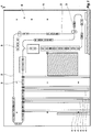
- Figure 1 shows a section of a CAD drawing of a production plant designated as a whole by 1.
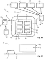
- Production facility 1 is also in Figure 21 outlined in a very simplified manner.
- the production plant 1 has a conveyor line 2, on which transport units 3 can be moved.
- the transport units 3, which are only shown schematically here, can be guided mechanically, inductively or in some other way along the conveyor section 2.
- the CAD drawing according to Figure 1 contains all data relevant to the construction of the conveyor line, such as envelopes, dimensions and explanations and the like.
- the CAD drawing according to Figure 1 contains, in addition to the conveyor section 3, surrounding systems, for example feeding and discharging conveyor technology 4.
- the CAD drawing according to Figure 1 finally also contains structural conditions such as walls 5 and rooms 6.
- Figure 20 shows in a greatly simplified schematic diagram a configuration device designated as a whole by 7.
- the configuration device 7 has a data input 8.
- CAD route data 9 can be entered via the data input 8, in particular by computer-assisted reading in of data.
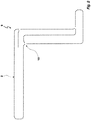
- the CAD route data 9 from the CAD drawing are shown in FIG Figure 1 placed in a separate layer, which in Figure 2 is shown.
- This layer is a grouping element in the CAD drawing.
- Figure 3 shows a further representation of the separated layer with the CAD route data 9 for the conveyor route 3.
- the position of the markers 11, the marker type and any user-defined attributes attached to the marker 11 contain, for example, relevant information for the system configuration, such as the position of RFID transponder chips, code of the transponder, start of barcode tape for position detection, end of barcode -Band for position detection and / or direction of the conveyor track 2.
- relevant information for the system configuration such as the position of RFID transponder chips, code of the transponder, start of barcode tape for position detection, end of barcode -Band for position detection and / or direction of the conveyor track 2.
- some or all of the information mentioned can be found at the branches 10, of which in Figure 3 only one is explicitly designated, or the markers 11 are deposited.
- the CAD route data 9 are fed into a processing unit 12 via the data input 8 (cf. Figure 20 ) read in and displayed and output in a virtual reality 13 on a screen 14 or the like.
- control data 15 are generated from the CAD route data 9, which data output 16 for a material flow computer 17, a higher-level control unit 18, an external simulation unit 19 and / or a parts list / calculation unit 20 for parameterizing or programming the mentioned units are provided.
- the units 17, 18, 19, 20 and / or further units mentioned are connected to the data output 16 via an interface 21.
- the CAD route data 9 can be stored and made available in a storage means 22.
- the data input 8 is formed here when reading out the storage means 22.
- control data 15 and / or a route layout 43 described in more detail below and created from the CAD route data 9 (cf. Fig. 4 ) can be stored in a storage means 23 and made available for further processing.
- Data output 16 set up to describe the storage means 23 with output data.
- meta data for the CAD route data 9 for example meta data for the markers 11 and / or meta data for the branches 10 or other meta data, can be provided for processing in the method according to the invention.
- the CAD route data 9 lie according to FIG Figure 3 in a separate layer at data input 8.
- the CAD route data 9 are preferably converted into the DXF data exchange format. This can take place before the data is provided at the data input 8 or after the CAD route data 9 has been read into the configuration device 7.
- Figure 4 shows a greatly simplified representation of a virtual reality 13, into which the conveyor line 2 was imported in this way.
- the conveyor line 2 is composed of straight line elements 25 and curved line elements 26.
- route elements with other shapes are also available, examples of possible route elements are: straight line, curve, diverter gate, diverter gate, tunnel area, transfer point. Other route elements can also be used.
- Each section element 25, 26 has at its ends connection points 27 at which the section elements 25, 26 are to be connected to form a continuous conveyor section 2. With the method according to the invention and in the configuration device according to the invention, these connections between the route elements 25, 26 are automatically established at the connection points 27 without an operator having to intervene.
- route element 25, 26 Before the automatic determination of these links of the route elements 25, 26 with one another, there is therefore no information in the configuration device 7 as to which route element 25, 26 is arranged in the course of the conveyor route 2 in front of or behind another route element 25, 26. Furthermore, there is still no travel direction information relating to the route elements 25, 26, which defines the direction of travel for each route element 25, 26 in the conveyor route 2.
- the conveyor section 2 is now composed of the section elements 25, 26.
- the connection points 27 define in a computer-readable manner how the route elements 25, 26 are connected and follow one another. A logical conveyor flow is therefore simulated in conveyor section 2.
- a set of rules for the error correction of the error-prone CAD route data 9 is stored. These rules are stored in a computer-readable manner and, for the computer-implemented solution, the CAD route end data 9 can be used in a computer-implemented manner to generate a route layout 43, for example the route layout already mentioned.
- a first route element 25, 26 is first selected.
- This can be, for example, a line element 25, 26 which is distinguished by its position, for example the element which is uppermost or lowest on a Y axis or the element which is uppermost or lowest on an X axis.
- This first route element 25, 26 can also be selected manually by a user or determined in some other way.
- driving direction information 28 is now read in or entered, which specifies the correct direction of travel for this route element 25, 26.
- Figure 5 shows in the upper half an example of a section of a conveyor section 2 with a straight section element 25.
- this route element 25 is the first route element just mentioned.
- the track element 25 has a connection point 27 at its ends.
- travel direction information 28 for the route element 25 which shows a direction of travel in Figure 5 defined from left to right.
- the left connection point 27 of the route element 25 is a starting point, while the right connection point 27 of the route element 25 is an end point.
- the processing unit 12 of the configuration device 7 now searches from the read CAD route data 9 for the route element which follows the selected route element 25 in the conveyor route 2.
- the curved track element 26 likewise has a connection point 27 at its ends.
- connection points 27 which are adjacent to one another are in Figure 5 shown and labeled separately.
- the processing unit 12 now checks to the right connection point 27 of the straight route element 25, which is indicated by the direction of travel information 28 as the end point, whether a further connection point 27 of a further route element can be found within a first distance threshold value to the right connection point 27 of the route element 25.
- the distance threshold is defined such that the connection points within a rectangle with predetermined side lengths these connection point 27 are arranged, are accepted as adjacent to the connection point and are linked to it.
- the distance threshold relates to a distance between two points in a two-dimensional grid, which by the larger value of the two values of the amount of the difference of the X coordinates of the points on the one hand and the amount of the difference of the Y coordinates of the points on the other hand is defined.
- the distance threshold value relates to other distance definitions, for example to the Euclidean distance, at which the square root is given from the sum of the square of the difference between the X coordinates and the square of the difference between the Y coordinates. This results in a circular window.
- a tangent to the route element 25 in the right connection point 27 of the route element 25 is first calculated in order to identify further connection points as candidates for a link by extrapolation or in another way.
- the route element 26 in Figure 5 checked whether a further connection point 30 can be found within the predetermined distance threshold.
- This further route element 29 is then linked to the route element 26 via the connection points 27, 30.
- route elements 26, 29 connected in this way and other route elements inherit driving direction information from the respectively preceding route element 25, 26, 29 in such a way that the direction of travel determined, for example, in the driving direction information 28 of the first route element is continued.
- the route elements 26, 29 automatically receive travel direction information 28, by means of which a connection point is designated as the starting point and a connection point 27 as the end point for each route element 25, 26, 29, each end point of a route element 25, 26, 29 having a Starting point of the link element 25, 26, 29 following in the conveyor section 2 is linked.
- connection point 30 is found within the first distance threshold value up to a connection point 27.
- the route layout created is now transferred to a vehicle controller of the transport unit 3, which is not known and is not known per se.
- the vehicle controller can then compare an actual position of the transport unit 3 with a target position described by the route layout 43.
- the result of this comparison can take place on a display unit and / or can be used to control the operating sequence. It is thus, for example, easy to implement that a display means determines the actual position and assigns it to a route element on the basis of its position information in a computer-implemented manner.
- the invention thus simultaneously realizes a method for computer-aided reproduction of a production system 1, the production system 1 having at least one conveyor line 2, CAD route data 9 being read into a processing unit 12 and a route layout 43 being generated in a computer-implemented manner from the CAD route data 9, which describes a logical conveyor flow of conveyor section 2 in a computer-readable manner.
- the advantage here is that a separate installation of the production plant is not necessary.
- connection points 27, 30 in the route layout 43 clearly state how the route elements 25, 26, 29 are connected, that is to say which route elements 25, 26, 29 follow which route elements 25, 26, 29.
- a logical conveying flow is thus defined by the route layout 43.
- the first distance threshold value is selected to be so small that it can be reliably excluded that two connecting points 27, 30 spaced apart from one another within the distance threshold value do not belong to a simple line of the conveyor section 2, but rather to a switch or branch.
- connection points 27 If there are still free connection points 27, it is checked whether these connection points have remained free, that is to say unlinked, only because of drawing errors. For this purpose, it is checked whether further connection points can be found within a second distance threshold value for these connection points. A drawing error is recognized for connection points for which only exactly one further connection point can be found within the second distance threshold value, and these connection points are linked.
- the second distance threshold is preferably chosen to be smaller than a gap in a switch or branching element.
- the next step is to search for the branches.
- connection point 27, 30 it is checked for all connection points 27, to which no adjacent connection point 27, 30 lies within the first or second distance threshold value, whether a connection point 27, 30 can be found within a third distance threshold value that is greater than the first distance threshold value.
- the third distance threshold defines a window 31. It can be seen that the connection point 27 of the route element 26 and the Connection point 30 of the route element 29 are within the third distance threshold value to the connection point 27 of the route element 25.
- connection point 27 of the route element 25 there is no further connection point in the window 31, which is arranged so closely adjacent to the connection point 27 of the route element 25 that it would be within the first or second distance threshold value to the connection point 27 of the route element 25.
- this is the criterion that a switch must be inserted in the route layout 43 within the window 31.
- the processing unit 12 now inserts a switch element (not shown further) in such a way that the connection point 27 of the route element 25 is connected or linked to the connection point 27 of the route element 26 and to the connection point 30 of the route element 29.
- connection points 27 and for the connection point 30 are calculated.
- the switch type can be clearly determined on the basis of the angles which the tangents enclose with one another, possibly extended to an intersection.
- the associated switch element or branching element or crossing element with more than three connecting points involved is then selected by the processing unit 12.
- a tangent calculation means 35 is formed in the processing unit 12.
- a distance determination means 36 for determining a distance between a connection point 27, 30 of a route element and a further connection point 27, 30 of a further route element 25, 26, 29 is formed in the processing unit 12, for example by suitable programming.
- a comparison means 37 is formed in the processing unit 12, for example by suitable programming.
- the route layout 43 calculated in this way can now still have free connection points 27.
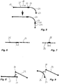
- the situation may change Figure 8 or the situation according to Figure 9 surrender.
- the distance determining means 36 determines the distance h of the further connection point 30 from the straight line element 25 in Figure 8 or of the curved track elements 26 in Figure 9 and of all further route elements (not shown) of the CAD route data 9. It is assumed that the route element 25 in FIG Figure 8 or the track element 26 in Figure 9 each form the closest route element.
- this distance h is determined, ie calculated, as the length of the solder on the respective route element 25 or 26.
- the comparison means 37 is now used to check whether this distance is smaller than a fourth distance threshold.
- the fourth distance threshold is set greater than the first distance threshold.
- the further connection point 30 is within the fourth distance threshold value to the straight track element 25 in Figure 8 or the curved track element 26 in Figure 9 .
- connection point 27 of the straight line element 25 is now reversed Figure 8 or the curved track element 26 in Figure 9 determined to the further route element 29, that is calculated.
- the length of the solder on the route element 29 is also calculated.
- the comparison means 37 is now used to check whether this distance is also within the fourth distance threshold.
- connection point 27 is in Figure 8 or. Figure 9 within the fourth distance threshold to the further route element 29.
- connection point 30 is within the fourth distance threshold value to the route element 25 or 26 and the connection point 27 is within the fourth distance threshold value to the further route element 29, then the connection point 27 is linked to the further connection point 30.
- the fourth distance threshold value is selected to be equal to the second distance threshold value.
- connection points 27, 30 linked in this way the coordinates of the connection points 27, 30 are changed in an error correction in such a way that the connection points 27, 30 linked to one another have matching coordinates.
- the processing unit 12 has a variation means 38 with which a parameter of the path elements 25, 26, 29, for example a length, a curvature, an extension along the X coordinate and / or an extension along the Y coordinate or a further parameter , is / are changeable.
- An arrow indicates the action of the variation means 38.
- the length of the further route element 29 is shortened as a parameter by the variation means 38 until the further connection point 30 has the same coordinates as the connection point 27.
- Figure 12 to 14 schematically shows the function of the variation means 38 in a situation analogous to Figure 9 .
- connection points 27, 30 coincide, the length of the further route element 29 can be shortened on the one hand with the variation means 38 until the connection point 27 lies at the same location as the further connection point 30.
- the radius of curvature of the curved track element 26 or the curved shape of the curved track element 26 can be changed with the variation means 38 until the connection point is brought into coincidence with the further connection point 30.
- Branching points 39 can be drawn in the CAD route data 9, particularly if they relate to ground transport systems, that is to say systems without mechanical tracking.
- Figure 15 shows such a branch point 39.
- branching points 39 are recognized by the processing unit 12 in that three connection points, namely a connection point 27 of the route element 25, a connection point 27 of the route element 26 and a connection point 30 of the route element 29, are arranged within the first distance threshold value.
- Such a branch 39 can, however, in the situation according to Figure 16 cannot be correctly recognized by the processing unit 12 since the route elements 25, 29 in Figure 19 are not separated from one another by a connection point 27, but instead a single straight, continuous route element 25 is present.
- connection point 27 of the route element 26 has no suitable connection point.
- the distance determining means 36 again calculates the distance of this connection point 27 of the route element 26 from the route element 25 by orthogonal projection of the point onto all route elements 25, 26, 29 of the CAD route data 9.
- a fifth distance threshold value which can be selected, for example, equal to the first distance threshold value or second distance threshold value or a distance threshold value below the first distance threshold value
- the processing unit 12 assumes that the connection point 27 lies on the route element 25.
- tangents 32, 33, 34 to the connection points 27 of the route elements 25, 26 are calculated. If these are the same or are within a predetermined angular range, there is branching. An intersection, on the other hand, has very different tangents.
- a subdivision means is formed in the processing unit 12, with which a further connection point 27 can be formed in a route element 25, 26, 29 between the associated connection points 27, 30, as a result of which the processed route element 25, 26, 29 is divided into two route elements and separated.
- this additional connection point is inserted as division point 41 such that its position coincides with the connection point 27 of the route element 26.
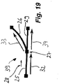
- Figure 19 explains how the direction of travel information 28 is transmitted at a branch point 39 from a route element 25 to the following route elements 26 and 29.
- the direction of travel information 28 for the route element 25, that is to say the route element arranged first in the direction of travel of the conveying route 2 defines a direction of travel which is oriented parallel (in the same direction) or antiparallel (in the opposite direction) to the tangent 32 of the route element 25.
- the travel direction information of the route elements 26 and 29 becomes the same chosen that the associated direction of travel are aligned parallel, ie in the same direction, to the respective tangents 33 and 34, respectively.
- the direction of travel information of the route elements 26, 29 is determined in such a way that there is a direction of travel which runs antiparallel, that is to say in the opposite direction, to the tangents 33 and 34, respectively.
- connection point 27 of the route element 26 lies within a fifth distance threshold value to the route element 25 and at the same time the connection point 27 of the route element 26 lies outside a sixth distance threshold value to the connection points 27 of the route element 25.
- the fifth distance threshold value can be selected to be equal to the first distance threshold value or smaller than the first distance threshold value or otherwise.
- the sixth distance threshold value can be selected equal to a fraction of a typical length of a route element, for example equal to half or two thirds of this length.
- a division point 41 is inserted in the route element 25, which marks the transition of a route element part formed by the division from the other, remaining route element part. From this division point 41, two connection points are automatically formed, each of which is assigned to one of the new route elements created from route element 25.
- the CAD route data 9 are thus automatically converted by the processing unit 12 into a route layout 43 of the conveyor route 2, wherein the route elements 43 link the route elements 25, 26, 29 of the conveyor route 2 at connection points 27, 30 and with direction of travel information 28 are provided in such a way that the conveyor section 2 is simulated in the virtual reality 13.
- This route layout 43 is now output via the data output 16 into the storage means 23 and is made available there for further processing in the form of control data 15.
- the route layout 43 can be fed to a material closing computer 17 in the form of control data 15 tailored to the material flow computer 17 or adapted to the material flow computer 17, in which the material flow in the conveyor line 2 can be calculated or simulated.
- the route layout 43 or at least a relevant part thereof is converted in a manner known per se into a data format which is matched to the material flow computer 17.
- the control data 15 then represent the information portion of the route layout 43 required for the material flow computer 17 in this data format.
- the route layout 43 can be supplied via the interface 21 to a control unit 18 in the form of control data 15 which is tailored to the control unit 18 or adapted to the control unit 18 and with which the production system 1 can be controlled in accordance with the data from the route layout 43.
- the route layout 43 is converted in a manner known per se into control data 15 for the control unit 18.
- the route layout 43 can alternatively or additionally be transmitted via the interface 21 to a simulation unit 19 in the form of control data 15 tailored to the simulation unit 19 or adapted to the simulation unit 19, in which sequence processes of the production plant 1 can be simulated with the data of the route layout 43.
- the route layout 43 is converted in a manner known per se into control data 15 for the simulation unit 19.
- the route layout 43 can alternatively or additionally be transmitted via the interface 21 to a parts list / calculation unit, in which, for example, parts lists for the conveyor line 2 to be set up and / or calculations for the conveyor line 2 with the data of the line layout 43, in the form of from Route layout 43 in control data 15 generated in a manner known per se are automatically calculated.
- the control data 15 can generally be transmitted as parameters.
- the invention thus also enables an inventive method in which the route layout 43 is transferred at least in parameter form or completely to a vehicle controller of a transport unit 3 traveling in the conveyor route 2.
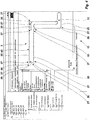
- the user can, for example, select the menu item "Device parameterization” for the corresponding part of production plant 1 (for example the transport units "AGV_01" to "AGV_05" or for the part "SC").
- the vehicle controller can be set up to control the transport unit 3 by comparing an actual position of the transport unit 3 with a target position described by the route layout 43.
- the vehicle controller can be set up for a corresponding evaluation of the route layout 43, for example for the extraction of target positions from the route layout 43.
- the route layout 43 and / or the or an at least locally one-dimensional, computer-readable description of the logical conveying flow is transferred to a control unit 18 and is used or provided for controlling transport units 3 of the production system 1.
- the advantage here is that manual steps during commissioning can be avoided and / or reduced.
- route layout 43 an error check is carried out in processing unit 12, in which it is checked for each route element 25, 26, 29 whether the assigned travel direction information 28 is compatible with one another and with the linkage. For example, it can be checked here whether a discharge switch or rather a feed switch should actually be provided at a certain point, since the two route elements differ in the direction of travel information.
- a route layout 43 is generated and data of the route layout 43 to the at least one transport unit 3 and / or the control unit 18 are transferred. Manual, time-consuming intermediate steps are unnecessary.
- the route layout 43 is transferred to a vehicle controller of the transport unit 3.
- the data of the route layout 43 can simply be transmitted in parameter form.
- the vehicle controller is set up to control the transport unit 3 by comparing an actual position of the transport unit 3 with a target position described by the route layout 43. In this case, no guidance is required, but the guidance results from the data of the route layout 43.
- the route layout 43 is converted into a locally one-dimensional, computer-readable description of the logical conveying flow. This description is then transferred to the control unit 18.
- the computer-readable description represents a set of control data 15.
- the transport units 3 of the production plant 1 are controlled on the basis of these control data.
Landscapes
- Engineering & Computer Science (AREA)
- General Engineering & Computer Science (AREA)
- Manufacturing & Machinery (AREA)
- Quality & Reliability (AREA)
- Physics & Mathematics (AREA)
- General Physics & Mathematics (AREA)
- Automation & Control Theory (AREA)
- General Factory Administration (AREA)
Priority Applications (1)
| Application Number | Priority Date | Filing Date | Title |
|---|---|---|---|
| PL13811789T PL2932339T3 (pl) | 2012-12-17 | 2013-12-13 | Sposób wspomaganego komputerowo odwzorowania urządzenia produkcyjnego, sposób uruchomienia urządzenia produkcyjnego, konfigurator i urządzenie produkcyjne |
Applications Claiming Priority (2)
| Application Number | Priority Date | Filing Date | Title |
|---|---|---|---|
| DE102012024582 | 2012-12-17 | ||
| PCT/EP2013/003769 WO2014095012A1 (de) | 2012-12-17 | 2013-12-13 | Verfahren zum computergestützten nachbilden einer produktionsanlage, verfahren zur inbetriebnahme einer produktionsanlage, konfigurationseinrichtung und produktionsanlage |
Publications (2)
| Publication Number | Publication Date |
|---|---|
| EP2932339A1 EP2932339A1 (de) | 2015-10-21 |
| EP2932339B1 true EP2932339B1 (de) | 2020-07-15 |
Family
ID=49880676
Family Applications (1)
| Application Number | Title | Priority Date | Filing Date |
|---|---|---|---|
| EP13811789.0A Revoked EP2932339B1 (de) | 2012-12-17 | 2013-12-13 | Verfahren zum computergestützten nachbilden einer produktionsanlage, verfahren zur inbetriebnahme einer produktionsanlage, konfigurationseinrichtung und produktionsanlage |
Country Status (5)
| Country | Link |
|---|---|
| EP (1) | EP2932339B1 (pl) |
| DE (1) | DE102013020582B4 (pl) |
| HU (1) | HUE051334T2 (pl) |
| PL (1) | PL2932339T3 (pl) |
| WO (1) | WO2014095012A1 (pl) |
Families Citing this family (2)
| Publication number | Priority date | Publication date | Assignee | Title |
|---|---|---|---|---|
| DE102019205691A1 (de) * | 2019-04-18 | 2020-10-22 | Volkswagen Aktiengesellschaft | System und Verfahren zur Simulation von Industrieprozessen |
| CN111897715B (zh) * | 2020-06-28 | 2024-07-12 | 通号城市轨道交通技术有限公司 | 一种仿真测试环境配置数据自动生成方法及装置 |
Citations (3)
| Publication number | Priority date | Publication date | Assignee | Title |
|---|---|---|---|---|
| US20060080827A1 (en) | 2003-06-05 | 2006-04-20 | Hirata Corporation | Assembling system, assembling unit, layout arranging system and layout arranging method |
| US20080154456A1 (en) | 2005-02-12 | 2008-06-26 | Manuel Escuriola Ettingshausen | Method for Operating a System, and Driver-Less Transport System |
| US20110257939A1 (en) | 2010-04-16 | 2011-10-20 | Thomas Baudisch | Method and an apparatus for automatically generating a target simulation model for a defined simulation object |
-
2013
- 2013-12-13 HU HUE13811789A patent/HUE051334T2/hu unknown
- 2013-12-13 WO PCT/EP2013/003769 patent/WO2014095012A1/de not_active Ceased
- 2013-12-13 EP EP13811789.0A patent/EP2932339B1/de not_active Revoked
- 2013-12-13 DE DE102013020582.4A patent/DE102013020582B4/de active Active
- 2013-12-13 PL PL13811789T patent/PL2932339T3/pl unknown
Patent Citations (3)
| Publication number | Priority date | Publication date | Assignee | Title |
|---|---|---|---|---|
| US20060080827A1 (en) | 2003-06-05 | 2006-04-20 | Hirata Corporation | Assembling system, assembling unit, layout arranging system and layout arranging method |
| US20080154456A1 (en) | 2005-02-12 | 2008-06-26 | Manuel Escuriola Ettingshausen | Method for Operating a System, and Driver-Less Transport System |
| US20110257939A1 (en) | 2010-04-16 | 2011-10-20 | Thomas Baudisch | Method and an apparatus for automatically generating a target simulation model for a defined simulation object |
Non-Patent Citations (11)
| Title |
|---|
| "AutoCAD Architecture 2011", 1 March 2010, article ANONYMOUS: "AUTCARD BENUTZERHANDBUCH", XP055965935 |
| "AutoCAD Architecture 2011. Benutzerhandbuch", 1 March 2010, AUTODESK INC, US, article "Kapitel 55. Anpassen und Hinzufügen neuer Symbole für Detailkomponenten", pages: 4433 - 4489, XP009538336 |
| 1 January 1993, ISBN: 978-3-89360-027-4, article AUGER W.: "AUTOCAD 12 FÜR DEN ANWENDER", XP055965928 |
| AUGER W.: "AutoCAD 12 für den Anwender (1. Aufl.)", 1 January 1993, BHV, Korschenbroich, ISBN: 3-89360-027-2, article AUGER, WOLFGANG: "Objekte einfangen; Die Abfragebefehle", pages: 231 - 253, XP009538337 |
| DAVID P. SLY: "Plant design for efficiency using AutoCAD and FactoryFLOW", 1995 WINTER SIMULATION CONFERENCE PROCEEDINGS, 1 December 1995 (1995-12-01) - 6 December 1995 (1995-12-06), pages 437 - 444, XP058090787, ISBN: 978-0-7803-3018-4, DOI: 10.1145/224401.224656 |
| ERTL F.: "AutoCAD 2010 Grundlagen", 11 February 2010, HANDWERKSKAMMER FÜR MÜNCHEN UND OBERBAYERN, DE, article ERTL, FRANZ: "Weitere Zeichen- und Änderungsbefehle", pages: 217 - 232, XP009538335 |
| ERTL F: " AutoCAD 2010 Grundlagen", TRAUNSTEIN BILDUNGSZENTRUM, 11 February 2010 (2010-02-11), XP055965933, [retrieved on 20220928] |
| PAPROTNY I ET AL: "Reducing model creation cycle time by automated conversion of a CAD AHMS layout design", WINTER SIMULATION CONFERENCE PROCEEDINGS, 1999 PHOENIX, AZ, USA 5-8 DEC. 1999, PISCATAWAY, NJ, USA,IEEE, US, vol. 1, 5 December 1999 (1999-12-05), pages 779 - 783, XP010368038, ISBN: 978-0-7803-5780-8 * |
| PAPROTNY I. ET AL.: "Reducing model creation cycle time by automated conversion of a CAD AMHS layout design", PROCEEDINGS OF THE 1999 WINTER SIMULATION CONFERENCE, 5 December 1999 (1999-12-05), Phoenix, AZ, USA, pages 779 - 783, XP058085590, ISBN: 978-0-7803-5780-8, DOI: 10.1145/324138.324477 |
| PAPROTNY I., ZHAO W., MACKULAK G.T.: "Reducing model creation cycle time by automated conversion of a CAD AHMS layout design", WINTER SIMULATION CONFERENCE PROCEEDINGS, 1999 PHOENIX, AZ, USA , vol. 1, 5 December 1999 (1999-12-05) - 8 December 1999 (1999-12-08), US , pages 779 - 783, XP010368038, ISBN: 978-0-7803-5780-8, DOI: 10.1145/324138.324477 |
| SLY D. P.: "PLANT DESIGN FOR EFFICIENCY USING AUTOCAD AND FACTORYFLOW.", 1995 WINTER SIMULATION CONFERENCE PROCEEDINGS. ARLINGTON, DEC. 3 - 6, 1995., NEW YORK, IEEE., US, 3 December 1995 (1995-12-03), US , pages 437 - 444., XP000631976, ISBN: 978-0-7803-3018-4, DOI: 10.1109/WSC.1995.478771 |
Also Published As
| Publication number | Publication date |
|---|---|
| DE102013020582B4 (de) | 2025-07-24 |
| DE102013020582A1 (de) | 2014-06-18 |
| PL2932339T3 (pl) | 2020-11-30 |
| EP2932339A1 (de) | 2015-10-21 |
| HUE051334T2 (hu) | 2021-03-01 |
| WO2014095012A1 (de) | 2014-06-26 |
Similar Documents
| Publication | Publication Date | Title |
|---|---|---|
| EP3446185B1 (de) | Verfahren und vorrichtung zur gestaltung eines produktionsprozesses zum produzieren eines aus mehreren teilprodukten zusammengesetzten produkts | |
| DE3401060A1 (de) | Verfahren zum grafischen darstellen eines gebildes | |
| WO2017050895A1 (de) | Robotersteuerung | |
| DE102019120633B4 (de) | Verfahren zur automatischen Bewegung eines Arbeitsgeräts sowie Arbeitsgerät | |
| WO2019020818A1 (de) | Effiziente programmierung von robotern für die bearbeitung von werkstücken mit verschiedenen varianten | |
| DE112008002573T5 (de) | Testen von Kompatibilität und Verhalten von Fertigungsautomatisierungssystemkomponenten mit einer virtuellen und realen Umgebung | |
| EP2952990B1 (de) | Optimiertes Steuern einer zerspanenden Werkzeugmaschine | |
| DE102020124734A1 (de) | Simulationsgerät | |
| DE112010002840T5 (de) | Automatische Programmiervorrichtung und automatisches Progammierverfahren | |
| DE102016211129A1 (de) | Verfahren zum Überprüfen einer Kollision zwischen zwei fahrerlosen Transportfahrzeugen, fahrerloses Transportfahrzeug und System mit mehreren fahrerlosen Transportfahrzeugen | |
| DE102008013400B4 (de) | Verfahren zur Ermittlung von Verriegelungsbereichen wenigstens eines im Raum bewegbaren ersten Objekts | |
| EP2407842A2 (de) | Verfahren zur Inbetriebnahme von Maschinen oder Maschinen einer Maschinenserie und Projektierungssystem | |
| WO2017005783A1 (de) | Computerimplementiertes verfahren zur bearbeitung von datenobjektvarianten | |
| DE102013020582B4 (de) | Verfahren zum computergestützten Nachbilden einer Produktionsanlage, Verfahren zur Inbetriebnahme einer Produktionsanlage, Konfigurationseinrichtung und Produktionsanlage | |
| DE112019007889T5 (de) | Bearbeitungsprogramm-umwandlungseinrichtung, numerische-steuereinrichtung und bearbeitungsprogramm-umwandlungsverfahren | |
| DE112020006647T5 (de) | Ursprungsrückführvorrichtung | |
| EP1430370B1 (de) | System und verfahren zur programmierung eines automatisierungssystems basierend auf impulsdiagrammen | |
| EP2191338B1 (de) | System zur erstellung eines simulationsprogramms | |
| EP4673931A1 (de) | Adaptive realdatenbasierte simulation eines zentralisiert koordinierten verkehrsraums | |
| EP0671027B1 (de) | Verfahren zum erstellen der anwendungsabhängigen logik eines freiprogrammierbaren schaltwerkes, einrichtung zur durchführung dieses verfahres und einrichtung zum betrieb eines steuerungssystems unter verwendung eines so erstellten programms | |
| EP1217477B1 (de) | Verfahren zur Parametrierung eines Prüfstandes bzw. Prüffeldes | |
| EP2299341A1 (de) | Editiergerät und Verfahren zur Konfigurierung von Parametern einer industriellen Automatisierungsanordnung | |
| EP2104885B1 (de) | Planungsvorrichtung und verfahren zur planung einer technischen anlage | |
| WO2004046973A2 (de) | Layout-orientierte erfassung von automatisierungsinformationen | |
| EP4485348B1 (de) | Computer-implementiertes verfahren und werkzeug zur optischen qualitätskontrolle von zwischen- oder endprodukten von produktionsanlagen sowie produktionsanlagensteuerung |
Legal Events
| Date | Code | Title | Description |
|---|---|---|---|
| PUAI | Public reference made under article 153(3) epc to a published international application that has entered the european phase |
Free format text: ORIGINAL CODE: 0009012 |
|
| 17P | Request for examination filed |
Effective date: 20150717 |
|
| AK | Designated contracting states |
Kind code of ref document: A1 Designated state(s): AL AT BE BG CH CY CZ DE DK EE ES FI FR GB GR HR HU IE IS IT LI LT LU LV MC MK MT NL NO PL PT RO RS SE SI SK SM TR |
|
| AX | Request for extension of the european patent |
Extension state: BA ME |
|
| DAX | Request for extension of the european patent (deleted) | ||
| STAA | Information on the status of an ep patent application or granted ep patent |
Free format text: STATUS: EXAMINATION IS IN PROGRESS |
|
| 17Q | First examination report despatched |
Effective date: 20190423 |
|
| GRAP | Despatch of communication of intention to grant a patent |
Free format text: ORIGINAL CODE: EPIDOSNIGR1 |
|
| STAA | Information on the status of an ep patent application or granted ep patent |
Free format text: STATUS: GRANT OF PATENT IS INTENDED |
|
| INTG | Intention to grant announced |
Effective date: 20200212 |
|
| GRAS | Grant fee paid |
Free format text: ORIGINAL CODE: EPIDOSNIGR3 |
|
| GRAA | (expected) grant |
Free format text: ORIGINAL CODE: 0009210 |
|
| STAA | Information on the status of an ep patent application or granted ep patent |
Free format text: STATUS: THE PATENT HAS BEEN GRANTED |
|
| AK | Designated contracting states |
Kind code of ref document: B1 Designated state(s): AL AT BE BG CH CY CZ DE DK EE ES FI FR GB GR HR HU IE IS IT LI LT LU LV MC MK MT NL NO PL PT RO RS SE SI SK SM TR |
|
| REG | Reference to a national code |
Ref country code: CH Ref legal event code: EP Ref country code: GB Ref legal event code: FG4D Free format text: NOT ENGLISH |
|
| REG | Reference to a national code |
Ref country code: DE Ref legal event code: R096 Ref document number: 502013014930 Country of ref document: DE |
|
| REG | Reference to a national code |
Ref country code: IE Ref legal event code: FG4D Free format text: LANGUAGE OF EP DOCUMENT: GERMAN |
|
| REG | Reference to a national code |
Ref country code: AT Ref legal event code: REF Ref document number: 1291705 Country of ref document: AT Kind code of ref document: T Effective date: 20200815 |
|
| REG | Reference to a national code |
Ref country code: LT Ref legal event code: MG4D |
|
| REG | Reference to a national code |
Ref country code: SK Ref legal event code: T3 Ref document number: E 35369 Country of ref document: SK |
|
| REG | Reference to a national code |
Ref country code: NL Ref legal event code: MP Effective date: 20200715 |
|
| PG25 | Lapsed in a contracting state [announced via postgrant information from national office to epo] |
Ref country code: NO Free format text: LAPSE BECAUSE OF FAILURE TO SUBMIT A TRANSLATION OF THE DESCRIPTION OR TO PAY THE FEE WITHIN THE PRESCRIBED TIME-LIMIT Effective date: 20201015 Ref country code: ES Free format text: LAPSE BECAUSE OF FAILURE TO SUBMIT A TRANSLATION OF THE DESCRIPTION OR TO PAY THE FEE WITHIN THE PRESCRIBED TIME-LIMIT Effective date: 20200715 Ref country code: BG Free format text: LAPSE BECAUSE OF FAILURE TO SUBMIT A TRANSLATION OF THE DESCRIPTION OR TO PAY THE FEE WITHIN THE PRESCRIBED TIME-LIMIT Effective date: 20201015 Ref country code: LT Free format text: LAPSE BECAUSE OF FAILURE TO SUBMIT A TRANSLATION OF THE DESCRIPTION OR TO PAY THE FEE WITHIN THE PRESCRIBED TIME-LIMIT Effective date: 20200715 Ref country code: PT Free format text: LAPSE BECAUSE OF FAILURE TO SUBMIT A TRANSLATION OF THE DESCRIPTION OR TO PAY THE FEE WITHIN THE PRESCRIBED TIME-LIMIT Effective date: 20201116 Ref country code: HR Free format text: LAPSE BECAUSE OF FAILURE TO SUBMIT A TRANSLATION OF THE DESCRIPTION OR TO PAY THE FEE WITHIN THE PRESCRIBED TIME-LIMIT Effective date: 20200715 Ref country code: GR Free format text: LAPSE BECAUSE OF FAILURE TO SUBMIT A TRANSLATION OF THE DESCRIPTION OR TO PAY THE FEE WITHIN THE PRESCRIBED TIME-LIMIT Effective date: 20201016 Ref country code: FI Free format text: LAPSE BECAUSE OF FAILURE TO SUBMIT A TRANSLATION OF THE DESCRIPTION OR TO PAY THE FEE WITHIN THE PRESCRIBED TIME-LIMIT Effective date: 20200715 Ref country code: SE Free format text: LAPSE BECAUSE OF FAILURE TO SUBMIT A TRANSLATION OF THE DESCRIPTION OR TO PAY THE FEE WITHIN THE PRESCRIBED TIME-LIMIT Effective date: 20200715 |
|
| PG25 | Lapsed in a contracting state [announced via postgrant information from national office to epo] |
Ref country code: RS Free format text: LAPSE BECAUSE OF FAILURE TO SUBMIT A TRANSLATION OF THE DESCRIPTION OR TO PAY THE FEE WITHIN THE PRESCRIBED TIME-LIMIT Effective date: 20200715 Ref country code: LV Free format text: LAPSE BECAUSE OF FAILURE TO SUBMIT A TRANSLATION OF THE DESCRIPTION OR TO PAY THE FEE WITHIN THE PRESCRIBED TIME-LIMIT Effective date: 20200715 Ref country code: IS Free format text: LAPSE BECAUSE OF FAILURE TO SUBMIT A TRANSLATION OF THE DESCRIPTION OR TO PAY THE FEE WITHIN THE PRESCRIBED TIME-LIMIT Effective date: 20201115 |
|
| REG | Reference to a national code |
Ref country code: HU Ref legal event code: AG4A Ref document number: E051334 Country of ref document: HU |
|
| PG25 | Lapsed in a contracting state [announced via postgrant information from national office to epo] |
Ref country code: NL Free format text: LAPSE BECAUSE OF FAILURE TO SUBMIT A TRANSLATION OF THE DESCRIPTION OR TO PAY THE FEE WITHIN THE PRESCRIBED TIME-LIMIT Effective date: 20200715 |
|
| REG | Reference to a national code |
Ref country code: DE Ref legal event code: R026 Ref document number: 502013014930 Country of ref document: DE |
|
| PLBI | Opposition filed |
Free format text: ORIGINAL CODE: 0009260 |
|
| PLAX | Notice of opposition and request to file observation + time limit sent |
Free format text: ORIGINAL CODE: EPIDOSNOBS2 |
|
| PG25 | Lapsed in a contracting state [announced via postgrant information from national office to epo] |
Ref country code: EE Free format text: LAPSE BECAUSE OF FAILURE TO SUBMIT A TRANSLATION OF THE DESCRIPTION OR TO PAY THE FEE WITHIN THE PRESCRIBED TIME-LIMIT Effective date: 20200715 Ref country code: CZ Free format text: LAPSE BECAUSE OF FAILURE TO SUBMIT A TRANSLATION OF THE DESCRIPTION OR TO PAY THE FEE WITHIN THE PRESCRIBED TIME-LIMIT Effective date: 20200715 Ref country code: DK Free format text: LAPSE BECAUSE OF FAILURE TO SUBMIT A TRANSLATION OF THE DESCRIPTION OR TO PAY THE FEE WITHIN THE PRESCRIBED TIME-LIMIT Effective date: 20200715 Ref country code: IT Free format text: LAPSE BECAUSE OF FAILURE TO SUBMIT A TRANSLATION OF THE DESCRIPTION OR TO PAY THE FEE WITHIN THE PRESCRIBED TIME-LIMIT Effective date: 20200715 Ref country code: RO Free format text: LAPSE BECAUSE OF FAILURE TO SUBMIT A TRANSLATION OF THE DESCRIPTION OR TO PAY THE FEE WITHIN THE PRESCRIBED TIME-LIMIT Effective date: 20200715 Ref country code: SM Free format text: LAPSE BECAUSE OF FAILURE TO SUBMIT A TRANSLATION OF THE DESCRIPTION OR TO PAY THE FEE WITHIN THE PRESCRIBED TIME-LIMIT Effective date: 20200715 |
|
| 26 | Opposition filed |
Opponent name: DS AUTOMOTION GMBH Effective date: 20210414 |
|
| PG25 | Lapsed in a contracting state [announced via postgrant information from national office to epo] |
Ref country code: AL Free format text: LAPSE BECAUSE OF FAILURE TO SUBMIT A TRANSLATION OF THE DESCRIPTION OR TO PAY THE FEE WITHIN THE PRESCRIBED TIME-LIMIT Effective date: 20200715 |
|
| REG | Reference to a national code |
Ref country code: CH Ref legal event code: PL |
|
| PLBB | Reply of patent proprietor to notice(s) of opposition received |
Free format text: ORIGINAL CODE: EPIDOSNOBS3 |
|
| PG25 | Lapsed in a contracting state [announced via postgrant information from national office to epo] |
Ref country code: SI Free format text: LAPSE BECAUSE OF FAILURE TO SUBMIT A TRANSLATION OF THE DESCRIPTION OR TO PAY THE FEE WITHIN THE PRESCRIBED TIME-LIMIT Effective date: 20200715 Ref country code: MC Free format text: LAPSE BECAUSE OF FAILURE TO SUBMIT A TRANSLATION OF THE DESCRIPTION OR TO PAY THE FEE WITHIN THE PRESCRIBED TIME-LIMIT Effective date: 20200715 |
|
| PG25 | Lapsed in a contracting state [announced via postgrant information from national office to epo] |
Ref country code: LU Free format text: LAPSE BECAUSE OF NON-PAYMENT OF DUE FEES Effective date: 20201213 Ref country code: IE Free format text: LAPSE BECAUSE OF NON-PAYMENT OF DUE FEES Effective date: 20201213 |
|
| PG25 | Lapsed in a contracting state [announced via postgrant information from national office to epo] |
Ref country code: LI Free format text: LAPSE BECAUSE OF NON-PAYMENT OF DUE FEES Effective date: 20201231 Ref country code: CH Free format text: LAPSE BECAUSE OF NON-PAYMENT OF DUE FEES Effective date: 20201231 |
|
| PGFP | Annual fee paid to national office [announced via postgrant information from national office to epo] |
Ref country code: DE Payment date: 20211231 Year of fee payment: 9 |
|
| REG | Reference to a national code |
Ref country code: AT Ref legal event code: MM01 Ref document number: 1291705 Country of ref document: AT Kind code of ref document: T Effective date: 20201213 |
|
| PG25 | Lapsed in a contracting state [announced via postgrant information from national office to epo] |
Ref country code: AT Free format text: LAPSE BECAUSE OF NON-PAYMENT OF DUE FEES Effective date: 20201213 |
|
| PG25 | Lapsed in a contracting state [announced via postgrant information from national office to epo] |
Ref country code: TR Free format text: LAPSE BECAUSE OF FAILURE TO SUBMIT A TRANSLATION OF THE DESCRIPTION OR TO PAY THE FEE WITHIN THE PRESCRIBED TIME-LIMIT Effective date: 20200715 Ref country code: MT Free format text: LAPSE BECAUSE OF FAILURE TO SUBMIT A TRANSLATION OF THE DESCRIPTION OR TO PAY THE FEE WITHIN THE PRESCRIBED TIME-LIMIT Effective date: 20200715 Ref country code: CY Free format text: LAPSE BECAUSE OF FAILURE TO SUBMIT A TRANSLATION OF THE DESCRIPTION OR TO PAY THE FEE WITHIN THE PRESCRIBED TIME-LIMIT Effective date: 20200715 |
|
| PG25 | Lapsed in a contracting state [announced via postgrant information from national office to epo] |
Ref country code: MK Free format text: LAPSE BECAUSE OF FAILURE TO SUBMIT A TRANSLATION OF THE DESCRIPTION OR TO PAY THE FEE WITHIN THE PRESCRIBED TIME-LIMIT Effective date: 20200715 |
|
| REG | Reference to a national code |
Ref country code: DE Ref legal event code: R103 Ref document number: 502013014930 Country of ref document: DE Ref country code: DE Ref legal event code: R064 Ref document number: 502013014930 Country of ref document: DE |
|
| RDAF | Communication despatched that patent is revoked |
Free format text: ORIGINAL CODE: EPIDOSNREV1 |
|
| PGFP | Annual fee paid to national office [announced via postgrant information from national office to epo] |
Ref country code: PL Payment date: 20220914 Year of fee payment: 10 |
|
| RDAG | Patent revoked |
Free format text: ORIGINAL CODE: 0009271 |
|
| STAA | Information on the status of an ep patent application or granted ep patent |
Free format text: STATUS: PATENT REVOKED |
|
| REG | Reference to a national code |
Ref country code: CH Ref legal event code: PL |
|
| REG | Reference to a national code |
Ref country code: FI Ref legal event code: MGE |
|
| 27W | Patent revoked |
Effective date: 20220706 |
|
| GBPR | Gb: patent revoked under art. 102 of the ep convention designating the uk as contracting state |
Effective date: 20220706 |
|
| PGFP | Annual fee paid to national office [announced via postgrant information from national office to epo] |
Ref country code: SK Payment date: 20221024 Year of fee payment: 10 Ref country code: GB Payment date: 20221103 Year of fee payment: 10 Ref country code: FR Payment date: 20221110 Year of fee payment: 10 |
|
| REG | Reference to a national code |
Ref country code: SK Ref legal event code: MC4A Ref document number: E 35369 Country of ref document: SK Effective date: 20220706 |
|
| PGFP | Annual fee paid to national office [announced via postgrant information from national office to epo] |
Ref country code: HU Payment date: 20221101 Year of fee payment: 10 Ref country code: BE Payment date: 20221226 Year of fee payment: 10 |
|
| REG | Reference to a national code |
Ref country code: AT Ref legal event code: MA03 Ref document number: 1291705 Country of ref document: AT Kind code of ref document: T Effective date: 20220706 |