EP2932339B1 - Method for the computer-assisted emulation of a production plant, method for activating a production plant, configuration device and production plant - Google Patents
Method for the computer-assisted emulation of a production plant, method for activating a production plant, configuration device and production plant Download PDFInfo
- Publication number
- EP2932339B1 EP2932339B1 EP13811789.0A EP13811789A EP2932339B1 EP 2932339 B1 EP2932339 B1 EP 2932339B1 EP 13811789 A EP13811789 A EP 13811789A EP 2932339 B1 EP2932339 B1 EP 2932339B1
- Authority
- EP
- European Patent Office
- Prior art keywords
- path
- route
- connection point
- data
- cad
- Prior art date
- Legal status (The legal status is an assumption and is not a legal conclusion. Google has not performed a legal analysis and makes no representation as to the accuracy of the status listed.)
- Revoked
Links
Images


Classifications
-
- G—PHYSICS
- G05—CONTROLLING; REGULATING
- G05B—CONTROL OR REGULATING SYSTEMS IN GENERAL; FUNCTIONAL ELEMENTS OF SUCH SYSTEMS; MONITORING OR TESTING ARRANGEMENTS FOR SUCH SYSTEMS OR ELEMENTS
- G05B19/00—Program-control systems
- G05B19/02—Program-control systems electric
- G05B19/418—Total factory control, i.e. centrally controlling a plurality of machines, e.g. direct or distributed numerical control [DNC], flexible manufacturing systems [FMS], integrated manufacturing systems [IMS] or computer integrated manufacturing [CIM]
- G05B19/4188—Total factory control, i.e. centrally controlling a plurality of machines, e.g. direct or distributed numerical control [DNC], flexible manufacturing systems [FMS], integrated manufacturing systems [IMS] or computer integrated manufacturing [CIM] characterised by CIM planning or realisation
-
- Y—GENERAL TAGGING OF NEW TECHNOLOGICAL DEVELOPMENTS; GENERAL TAGGING OF CROSS-SECTIONAL TECHNOLOGIES SPANNING OVER SEVERAL SECTIONS OF THE IPC; TECHNICAL SUBJECTS COVERED BY FORMER USPC CROSS-REFERENCE ART COLLECTIONS [XRACs] AND DIGESTS
- Y02—TECHNOLOGIES OR APPLICATIONS FOR MITIGATION OR ADAPTATION AGAINST CLIMATE CHANGE
- Y02P—CLIMATE CHANGE MITIGATION TECHNOLOGIES IN THE PRODUCTION OR PROCESSING OF GOODS
- Y02P90/00—Enabling technologies with a potential contribution to greenhouse gas [GHG] emissions mitigation
- Y02P90/02—Total factory control, e.g. smart factories, flexible manufacturing systems [FMS] or integrated manufacturing systems [IMS]
Definitions
- the invention relates to a method for computer-aided reproduction of a production system, a method for starting up a production system, a configuration device and a production system.
- the invention has for its object to automate the engineering design and / or commissioning of production facilities.
- This object is achieved according to the invention in a method by the features of claim 1, in a method for starting up a production system by the features of claim 14, in a configuration device by the features of claim 15 and in a production system by the features of claim 20.
- Important features of the invention of a method for computer-aided replication of a production system are that CAD route data are read into a processing unit and that a route layout is generated in a computer-implemented manner from the CAD route data, which logic route conveying flow of the conveyor route describes computer-readable.
- the advantage here is that the route layout contains data which can be used for a computer-aided simulation, display, monitoring and / or control of a driving operation on the conveyor route and / or a conveyor flow on the conveyor route.
- the invention thus makes it possible to provide a route layout that can be used for parameterization, checking, simulation, control and / or modification of motion sequences.
- the project planning and commissioning of a production plant can thus be considerably simplified.
- the CAD route data is error-prone, that a set of rules, for example the set of rules mentioned below, has rules for error correction of the error-prone CAD route data and that these rules apply to the CAD route end data for generating a route layout, for example the one already mentioned route layouts can be applied in a computer-implemented way.
- the CAD route data can be faulty, for example, because the CAD models were not created with the required accuracy.
- the storage of rules has the advantage that the CAD route data can be prepared in an automated process for use in a downstream control.
- successive route elements of the CAD route data are logically linked in order to generate the route layout in the logical conveying flow.
- the advantage here is that a relationship between the route elements can be determined and defined.
- a sequence of the route elements in the logical conveying flow can thus be defined in a computer-readable manner. It is particularly favorable if the route elements here at connection points, preferably at all connection points of each route element, be linked. In this way, it is easy to form coherent sections of the route layout that describe or specify a logical flow of funding.
- the route layout contains two- or three-dimensional position information on route elements of the route layout.
- the advantage here is that the route layout can be used to regulate an actual position of transport units to a target position.
- the respective transport unit can be set up to extract target positions for its own, preferably measured or ascertained, actual position.
- an at least locally one-dimensional, computer-readable description of the logical conveying flow is derived from the route layout.
- An intrinsic description of the conveyor line that is to say without reference to the position, the course and / or the embedding of the conveyor line in space, can thus be provided and / or used.
- branches and / or switches are permissible, and the description is one-dimensional beyond the branches and / or switches.
- a sequence in the logical flow of funding can thus be described or specified with minimal data expenditure.
- the route layout is transferred, at least in parameter form, to a vehicle controller of a transport unit traveling in the conveyor route.
- the advantage here is that the transport units can be automatically parameterized, set up and / or put into operation. Manual processing steps are largely or even completely dispensable.
- the vehicle controller is set up to control the transport unit on the basis of a comparison of an actual position of the transport unit with a target position described by the route layout.
- the advantage here is that the two-dimensional position information of the route layout, which was derived from the CAD route data, can be used for tracking.
- the route layout and / or the or at least locally one-dimensional, computer-readable description of the logical conveying flow is transferred to a control unit and used or provided to control transport units of the production plant.
- the advantage here is that manual commissioning of the production system is not necessary.
- important features of the invention are a method for computer-aided replication of a production system, the production system having at least one conveyor line, CAD route data being read into a processing unit, the CAD route data being displayed automatically in a virtual reality and control data being triggered an interface designed for at least one element from the group of material flow computer, superordinate control unit, external simulation unit and parts list / calculation unit is provided automatically.
- the advantage here is that the production system can be simulated in a virtual reality. This enables the control programs of the production plant to be parameterized accordingly.
- Important features of the invention of a method for computer-aided reproduction of a production system, in particular as described above and / or according to claim 1, wherein the production system has at least one conveyor line, are alternatively or additionally that CAD route data are read into a processing unit, the CAD Route data comprise at least route elements from which the conveyor route is formed, and that the route elements are automatically linked to a rule system to form a route layout and are provided for a computer-aided replica of the conveyor route.
- the advantage here is that the route layout can be obtained automatically. This means that the total amount of work required to start the system simulation can be reduced. Assignment errors when creating the route layout can also be avoided.
- the processing unit is preferably designed as a data processing unit or in some other way for the automated process.
- route elements are to be understood as placeholders in the rules described in each case.
- a first connection point of a first route element is automatically linked to a second connection point of a second route element if the first connection point of the first route element is within a first distance threshold to the second connection point of the second route element.
- the advantage here is that in the CAD drawing separate route elements are automatically recognized and recognized as being adjacent to one another in the conveyor route.
- the distance threshold value is preferably selected such that random gaps in the conveyor line can be automatically differentiated from deliberately left gaps, over which no conveyor line runs, due to drawing inaccuracies in the CAD route data.
- the first distance threshold value can be a fraction, for example less than half or less than a tenth, of an average or minimum length of the route elements.
- a first connection point of a first route element is linked to a second connection point of a second route element if the first connection point of the first route element is within a second distance threshold to the second connection point of the second route element and if there is no third Connection point of a third route element is located within the or a first distance threshold value to the first and / or second connection point.
- switches are removed from the CAD route data before the route layout is created. This has the advantage that it is not necessary to recognize and differentiate between the different types of switches that can occur.
- switch types are identified and / or classified using a feature and / or pattern recognition algorithm. This enables a further improved accuracy in the automated setup of branch points in the route layout.
- a switch element or a branching element is automatically inserted into the route layout if a connection point of a first route element is linked to a connection point of at least two further route elements.
- the connection points involved are thus linked indirectly (via the inserted element).
- the advantage here is that branches can be automatically recognized and included in the route layout without the need for complex feature or pattern recognition.
- a branching element differs from a switch element in that in the case of a branching element at least three route elements are permanently connected, while in the case of a switch element different connections of individual route elements can be produced by different states.
- the route elements of the CAD route data which have at least one connection point to which there is no connection point of a further route element within the or a (first) distance threshold value
- an automatic check is made as to whether this connection point is located of the route element is located within a second distance threshold value to a connection point of a further route element.
- branches can be automatically distinguished from random gaps.
- the second distance threshold value is preferably selected to be greater than the first distance threshold value. If there is only a single further connection point within the second distance threshold value, it can be provided that an unwanted gap in the CAD drawing is automatically recognized and this further connection point is automatically linked to the previously mentioned connection point.
- connection point of a first route element to which no connection point of a further route element can be found within the second distance threshold value, which route element lies within a third distance threshold value to the first connection point.
- the advantage here is that even larger gaps in the course of the route in the CAD route data, which resulted, for example, after deleting a switch element, can be processed.
- the third distance threshold value is preferably greater than the second distance threshold value and particularly preferably chosen to be so large that all switch elements that occur or can be used have an extent that is smaller than the third distance threshold value. The connection points which are connected via a branching or switch element can thus be identified automatically.
- a first connection point of a first route element is linked to a second connection point of a second route element if the first connection point within one or the fourth distance threshold value to the second route element and the second connection point within the fourth distance threshold value to the first Line element lies.
- An automated method for connecting route elements can thus be carried out, which automatically identifies and connects route elements offset laterally with respect to one another in the direction of travel of the conveyor route.
- the fourth distance threshold value can, for example, be chosen to be equal to the second distance threshold value.
- a parameter of a route element in which a first connection point is linked to exactly one second connection point of a further route element is changed until the first connection point lies within the first distance threshold value from the second connection point.
- a first route element at a division point is divided into two further route elements if a connection point of a second route element lies within a fifth distance threshold value to the first route element but outside a sixth distance threshold value to the connection points of the first route element, whereby each of the two further route elements receives a connection point from the first route element and receives a further connection point at the division point, these further connection points being linked to one another.
- the advantage here is that missing branching points can be automatically generated at points where a second route element encounters a first route element.
- the fifth distance threshold value can, for example, be selected to be equal to the first or second distance threshold value.
- the sixth distance threshold value can, for example, be selected to be equal to the second or third distance threshold value.
- the sixth distance threshold can be a fraction, for example half or a third, of a typical, average or minimum dimension of the route elements. It is therefore easy to automatically recognize when a connection point of the second route element lies approximately centrally between the connection points on the first route element.
- a connection point of this route element is characterized as a starting point and a further connection point of this route element as an end point using travel direction information of a route element.
- the advantage here is that automatic consistency checks can be carried out. For example, it can be checked whether start points of a route element are connected to end points of the adjacent route element in the route layout.
- direction information for a first route element is derived from direction information of a second route element such that a starting point is linked to an end point.
- a tangent to this route element is calculated at a connection point of a route element. It is advantageous here that route elements that are incorrectly spaced from a route element in the CAD route data can be identified.
- a connection point for linking can also be selected on the basis of the calculated tangent between several connection points of other stretching elements.
- a branching, switching and / or crossing element is / are selected automatically on the basis of the calculated tangents of the connecting points involved.
- the advantage here is that branching points with a low error rate in the route layout can be generated in the correct positions.
- the invention makes use of the fact that switches and branches can be described and / or classified for automatic processing by the relative position of the tangents at the connection points.
- the tangent at a connection point can be calculated or determined by analyzing the course of the associated route element in the immediate vicinity of the connection point.
- a control program for transport units that can be moved on the conveyor route is created and / or output for the route layout.
- the advantage here is that a simulation of the plant operation can be carried out after the automated preparation of the CAD route data has been completed.
- a material flow computer is controlled with the control program.
- the advantage here is that a material flow on the production system with the result of the preparation or processing of the CAD route data can be simulated or controlled during operation.
- control program is used to program a control unit of the production system and / or a simulation unit which is set up to simulate an operating sequence of a conveyor line with transport units.
- the advantage here is that the prepared CAD route data can be further processed.
- the route elements are extracted from the CAD route data and written into a separate layer.
- the advantage here is that the route elements can be processed individually to generate the route layout.
- the use of layers ensures that the position information of the route elements is retained when extracted from the CAD route data.
- an error check is carried out in which a unique and / or compatible assignment of route information is checked for each route element. This means that assignment errors are automatically recognized.
- the invention is used in a method for starting up a production system with at least one transport unit that can be moved along a conveyor line and a control unit, with a method according to the invention for emulating a production system, in particular as described above and / or according to one of the methods for computer-assisted emulation claims of a production plant, a route layout is generated and data of the route layout are transferred to the at least one transport unit and / or the control unit.
- two-dimensional position information on route elements of the route layout are transmitted to the at least one transport unit and one-dimensional position information at least locally is transmitted to the control unit.
- a processing unit for executing a method according to the invention in particular as described above and / or according to a of the claims directed to a method for emulating a production plant, is designed and set up.
- the advantage here is that a means for automated, for example computer-aided, processing of the method according to the invention can be provided.
- the configuration device can be provided by a computer set up to carry out the method according to the invention, in particular set up by configuration and / or programming.
- the CAD route data have route elements each provided with two connection points.
- the advantage here is that automatic linkage of route elements belonging together can be carried out.
- the CAD route data preferably also have route elements provided with metadata, for example travel direction information, positions of waymarks and the like route-related metadata.
- a distance determining means is designed to determine a distance between a connection point of a route element and a further route element.
- the advantage here is that adjacent route elements can be identified.
- the distance determining means can be designed to calculate or determine a Euclidean distance of the connection point or to calculate or determine a maximum of a difference in the X coordinates of the connection points on the one hand and a difference in the Y coordinates of the connection points on the other hand.
- a comparison means is designed to compare a distance between a connection point of a route element and a further route element with a distance threshold.
- this distance threshold can be at least one element from the group of first, second, third, fourth, fifth and / or sixth distance threshold.
- a variation means is set up to vary a parameter of a route element.
- These parameters can be, for example, the length or the radius of curvature or the like dimensions describing the shape of a route element.
- display errors in the CAD route data can be corrected automatically.
- the route layout is preferably corrected until discontinuities, for example lateral displacements, and kinks, for example discontinuities in a first derivation of the course of the conveyor line, in the conveyor line or the conveyor lines can be eliminated or eliminated.
- a tangent calculation means is designed for calculating a tangent in a connection point of a route element to the route element.
- the advantage here is that a means for extrapolating the route is designed, with which adjacent route elements, spaced apart by random or deliberately left gaps, can be identified as belonging together and - for example via a switch element - can be linked.
- a subdivision means is designed to divide a route element at a division point into two further route elements.
- the advantage here is that branching points that are missing in the CAD route data can be subsequently reconstructed.
- an assignment means is designed to assign travel direction information to a route element.
- the advantage here is that the route layout can be equipped with travel direction information, for example for an error and / or plausibility check.
- a material flow computer and / or a calculation tool and / or a control unit and / or a simulation tool is / are connectable to the data output.
- the advantage here is that computer-aided further processing of the calculated route layout can be carried out.
- a storage means in particular a database, with metadata relating to route elements of the CAD route data can be connected to the data input or a further data input.
- metadata relating to route elements of the CAD route data
- a control unit is in control connection with a configuration device according to the invention, in particular as described above and / or according to one of the claims directed to a configuration device.
- the advantage here is that the production system can be controlled using the route layout used in the simulation. Errors that could result when the route layout is transferred to the control unit can thus be avoided.
- a control unit with a configuration device according to the invention can be programmed by a configuration device, in particular as described above and / or according to one of the claims directed to a configuration device.
- the advantage here is that a control program that was created and / or used in the simulation can be used in the programming of the production system.
- the route layout can be transferred at least in parameter form to a vehicle control of the transport unit.
- the vehicle controller is set up to control the transport unit on the basis of a comparison of an actual position of the transport unit with a target position described by the route layout.
- Driverless transport systems and other systems with trackless transport units can thus be operated.
- the actual position can preferably be determined, for example measurable, and / or is determined, for example measured, in relation to a leader and / or marker.
- the route layout can be transferred to the control unit and used to control transport units Production plant is usable.
- the advantage here is that the control unit receives data with which a control of the production system can be carried out.
- the route layout in particular for each route element of the conveyor route, contains area data which describe or specify a driving behavior in the route element. For example, a cyclic driving behavior, a continuous driving behavior, a pearl chain driving behavior in which a traversing movement of a transport unit is coupled to a traversing movement of a further transport unit, and / or a synchronous driving behavior or combinations of these driving behaviors can be specified. Other driving behavior can also be advantageously specified.
- the or an at least locally one-dimensional, computer-readable description of the logical conveying flow can be transferred to the control unit and can be used to control transport units of the production system.
- the advantage here is that the amount of data is reduced.
- the control unit does not require any spatial position data if the transport units automatically determine their route and / or if the transport units are guided.
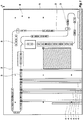
- Figure 1 shows a section of a CAD drawing of a production plant designated as a whole by 1.
- Production facility 1 is also in Figure 21 outlined in a very simplified manner.
- the production plant 1 has a conveyor line 2, on which transport units 3 can be moved.
- the transport units 3, which are only shown schematically here, can be guided mechanically, inductively or in some other way along the conveyor section 2.
- the CAD drawing according to Figure 1 contains all data relevant to the construction of the conveyor line, such as envelopes, dimensions and explanations and the like.
- the CAD drawing according to Figure 1 contains, in addition to the conveyor section 3, surrounding systems, for example feeding and discharging conveyor technology 4.
- the CAD drawing according to Figure 1 finally also contains structural conditions such as walls 5 and rooms 6.
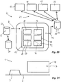
- Figure 20 shows in a greatly simplified schematic diagram a configuration device designated as a whole by 7.
- the configuration device 7 has a data input 8.
- CAD route data 9 can be entered via the data input 8, in particular by computer-assisted reading in of data.
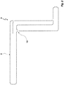
- the CAD route data 9 from the CAD drawing are shown in FIG Figure 1 placed in a separate layer, which in Figure 2 is shown.
- This layer is a grouping element in the CAD drawing.
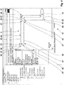
- Figure 3 shows a further representation of the separated layer with the CAD route data 9 for the conveyor route 3.
- the position of the markers 11, the marker type and any user-defined attributes attached to the marker 11 contain, for example, relevant information for the system configuration, such as the position of RFID transponder chips, code of the transponder, start of barcode tape for position detection, end of barcode -Band for position detection and / or direction of the conveyor track 2.
- relevant information for the system configuration such as the position of RFID transponder chips, code of the transponder, start of barcode tape for position detection, end of barcode -Band for position detection and / or direction of the conveyor track 2.
- some or all of the information mentioned can be found at the branches 10, of which in Figure 3 only one is explicitly designated, or the markers 11 are deposited.
- the CAD route data 9 are fed into a processing unit 12 via the data input 8 (cf. Figure 20 ) read in and displayed and output in a virtual reality 13 on a screen 14 or the like.
- control data 15 are generated from the CAD route data 9, which data output 16 for a material flow computer 17, a higher-level control unit 18, an external simulation unit 19 and / or a parts list / calculation unit 20 for parameterizing or programming the mentioned units are provided.
- the units 17, 18, 19, 20 and / or further units mentioned are connected to the data output 16 via an interface 21.
- the CAD route data 9 can be stored and made available in a storage means 22.
- the data input 8 is formed here when reading out the storage means 22.
- control data 15 and / or a route layout 43 described in more detail below and created from the CAD route data 9 (cf. Fig. 4 ) can be stored in a storage means 23 and made available for further processing.
- Data output 16 set up to describe the storage means 23 with output data.
- meta data for the CAD route data 9 for example meta data for the markers 11 and / or meta data for the branches 10 or other meta data, can be provided for processing in the method according to the invention.
- the CAD route data 9 lie according to FIG Figure 3 in a separate layer at data input 8.
- the CAD route data 9 are preferably converted into the DXF data exchange format. This can take place before the data is provided at the data input 8 or after the CAD route data 9 has been read into the configuration device 7.
- Figure 4 shows a greatly simplified representation of a virtual reality 13, into which the conveyor line 2 was imported in this way.
- the conveyor line 2 is composed of straight line elements 25 and curved line elements 26.
- route elements with other shapes are also available, examples of possible route elements are: straight line, curve, diverter gate, diverter gate, tunnel area, transfer point. Other route elements can also be used.
- Each section element 25, 26 has at its ends connection points 27 at which the section elements 25, 26 are to be connected to form a continuous conveyor section 2. With the method according to the invention and in the configuration device according to the invention, these connections between the route elements 25, 26 are automatically established at the connection points 27 without an operator having to intervene.
- route element 25, 26 Before the automatic determination of these links of the route elements 25, 26 with one another, there is therefore no information in the configuration device 7 as to which route element 25, 26 is arranged in the course of the conveyor route 2 in front of or behind another route element 25, 26. Furthermore, there is still no travel direction information relating to the route elements 25, 26, which defines the direction of travel for each route element 25, 26 in the conveyor route 2.
- the conveyor section 2 is now composed of the section elements 25, 26.
- the connection points 27 define in a computer-readable manner how the route elements 25, 26 are connected and follow one another. A logical conveyor flow is therefore simulated in conveyor section 2.
- a set of rules for the error correction of the error-prone CAD route data 9 is stored. These rules are stored in a computer-readable manner and, for the computer-implemented solution, the CAD route end data 9 can be used in a computer-implemented manner to generate a route layout 43, for example the route layout already mentioned.
- a first route element 25, 26 is first selected.
- This can be, for example, a line element 25, 26 which is distinguished by its position, for example the element which is uppermost or lowest on a Y axis or the element which is uppermost or lowest on an X axis.
- This first route element 25, 26 can also be selected manually by a user or determined in some other way.
- driving direction information 28 is now read in or entered, which specifies the correct direction of travel for this route element 25, 26.
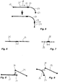
- Figure 5 shows in the upper half an example of a section of a conveyor section 2 with a straight section element 25.
- this route element 25 is the first route element just mentioned.
- the track element 25 has a connection point 27 at its ends.
- travel direction information 28 for the route element 25 which shows a direction of travel in Figure 5 defined from left to right.
- the left connection point 27 of the route element 25 is a starting point, while the right connection point 27 of the route element 25 is an end point.
- the processing unit 12 of the configuration device 7 now searches from the read CAD route data 9 for the route element which follows the selected route element 25 in the conveyor route 2.
- the curved track element 26 likewise has a connection point 27 at its ends.
- connection points 27 which are adjacent to one another are in Figure 5 shown and labeled separately.
- the processing unit 12 now checks to the right connection point 27 of the straight route element 25, which is indicated by the direction of travel information 28 as the end point, whether a further connection point 27 of a further route element can be found within a first distance threshold value to the right connection point 27 of the route element 25.
- the distance threshold is defined such that the connection points within a rectangle with predetermined side lengths these connection point 27 are arranged, are accepted as adjacent to the connection point and are linked to it.
- the distance threshold relates to a distance between two points in a two-dimensional grid, which by the larger value of the two values of the amount of the difference of the X coordinates of the points on the one hand and the amount of the difference of the Y coordinates of the points on the other hand is defined.
- the distance threshold value relates to other distance definitions, for example to the Euclidean distance, at which the square root is given from the sum of the square of the difference between the X coordinates and the square of the difference between the Y coordinates. This results in a circular window.
- a tangent to the route element 25 in the right connection point 27 of the route element 25 is first calculated in order to identify further connection points as candidates for a link by extrapolation or in another way.
- the route element 26 in Figure 5 checked whether a further connection point 30 can be found within the predetermined distance threshold.
- This further route element 29 is then linked to the route element 26 via the connection points 27, 30.
- route elements 26, 29 connected in this way and other route elements inherit driving direction information from the respectively preceding route element 25, 26, 29 in such a way that the direction of travel determined, for example, in the driving direction information 28 of the first route element is continued.
- the route elements 26, 29 automatically receive travel direction information 28, by means of which a connection point is designated as the starting point and a connection point 27 as the end point for each route element 25, 26, 29, each end point of a route element 25, 26, 29 having a Starting point of the link element 25, 26, 29 following in the conveyor section 2 is linked.
- connection point 30 is found within the first distance threshold value up to a connection point 27.
- the route layout created is now transferred to a vehicle controller of the transport unit 3, which is not known and is not known per se.
- the vehicle controller can then compare an actual position of the transport unit 3 with a target position described by the route layout 43.
- the result of this comparison can take place on a display unit and / or can be used to control the operating sequence. It is thus, for example, easy to implement that a display means determines the actual position and assigns it to a route element on the basis of its position information in a computer-implemented manner.
- the invention thus simultaneously realizes a method for computer-aided reproduction of a production system 1, the production system 1 having at least one conveyor line 2, CAD route data 9 being read into a processing unit 12 and a route layout 43 being generated in a computer-implemented manner from the CAD route data 9, which describes a logical conveyor flow of conveyor section 2 in a computer-readable manner.
- the advantage here is that a separate installation of the production plant is not necessary.
- connection points 27, 30 in the route layout 43 clearly state how the route elements 25, 26, 29 are connected, that is to say which route elements 25, 26, 29 follow which route elements 25, 26, 29.
- a logical conveying flow is thus defined by the route layout 43.
- the first distance threshold value is selected to be so small that it can be reliably excluded that two connecting points 27, 30 spaced apart from one another within the distance threshold value do not belong to a simple line of the conveyor section 2, but rather to a switch or branch.
- connection points 27 If there are still free connection points 27, it is checked whether these connection points have remained free, that is to say unlinked, only because of drawing errors. For this purpose, it is checked whether further connection points can be found within a second distance threshold value for these connection points. A drawing error is recognized for connection points for which only exactly one further connection point can be found within the second distance threshold value, and these connection points are linked.
- the second distance threshold is preferably chosen to be smaller than a gap in a switch or branching element.
- the next step is to search for the branches.
- connection point 27, 30 it is checked for all connection points 27, to which no adjacent connection point 27, 30 lies within the first or second distance threshold value, whether a connection point 27, 30 can be found within a third distance threshold value that is greater than the first distance threshold value.
- the third distance threshold defines a window 31. It can be seen that the connection point 27 of the route element 26 and the Connection point 30 of the route element 29 are within the third distance threshold value to the connection point 27 of the route element 25.
- connection point 27 of the route element 25 there is no further connection point in the window 31, which is arranged so closely adjacent to the connection point 27 of the route element 25 that it would be within the first or second distance threshold value to the connection point 27 of the route element 25.
- this is the criterion that a switch must be inserted in the route layout 43 within the window 31.
- the processing unit 12 now inserts a switch element (not shown further) in such a way that the connection point 27 of the route element 25 is connected or linked to the connection point 27 of the route element 26 and to the connection point 30 of the route element 29.
- connection points 27 and for the connection point 30 are calculated.
- the switch type can be clearly determined on the basis of the angles which the tangents enclose with one another, possibly extended to an intersection.
- the associated switch element or branching element or crossing element with more than three connecting points involved is then selected by the processing unit 12.
- a tangent calculation means 35 is formed in the processing unit 12.
- a distance determination means 36 for determining a distance between a connection point 27, 30 of a route element and a further connection point 27, 30 of a further route element 25, 26, 29 is formed in the processing unit 12, for example by suitable programming.
- a comparison means 37 is formed in the processing unit 12, for example by suitable programming.
- the route layout 43 calculated in this way can now still have free connection points 27.
- the situation may change Figure 8 or the situation according to Figure 9 surrender.
- the distance determining means 36 determines the distance h of the further connection point 30 from the straight line element 25 in Figure 8 or of the curved track elements 26 in Figure 9 and of all further route elements (not shown) of the CAD route data 9. It is assumed that the route element 25 in FIG Figure 8 or the track element 26 in Figure 9 each form the closest route element.
- this distance h is determined, ie calculated, as the length of the solder on the respective route element 25 or 26.
- the comparison means 37 is now used to check whether this distance is smaller than a fourth distance threshold.
- the fourth distance threshold is set greater than the first distance threshold.
- the further connection point 30 is within the fourth distance threshold value to the straight track element 25 in Figure 8 or the curved track element 26 in Figure 9 .
- connection point 27 of the straight line element 25 is now reversed Figure 8 or the curved track element 26 in Figure 9 determined to the further route element 29, that is calculated.
- the length of the solder on the route element 29 is also calculated.
- the comparison means 37 is now used to check whether this distance is also within the fourth distance threshold.
- connection point 27 is in Figure 8 or. Figure 9 within the fourth distance threshold to the further route element 29.
- connection point 30 is within the fourth distance threshold value to the route element 25 or 26 and the connection point 27 is within the fourth distance threshold value to the further route element 29, then the connection point 27 is linked to the further connection point 30.
- the fourth distance threshold value is selected to be equal to the second distance threshold value.
- connection points 27, 30 linked in this way the coordinates of the connection points 27, 30 are changed in an error correction in such a way that the connection points 27, 30 linked to one another have matching coordinates.
- the processing unit 12 has a variation means 38 with which a parameter of the path elements 25, 26, 29, for example a length, a curvature, an extension along the X coordinate and / or an extension along the Y coordinate or a further parameter , is / are changeable.
- An arrow indicates the action of the variation means 38.
- the length of the further route element 29 is shortened as a parameter by the variation means 38 until the further connection point 30 has the same coordinates as the connection point 27.
- Figure 12 to 14 schematically shows the function of the variation means 38 in a situation analogous to Figure 9 .
- connection points 27, 30 coincide, the length of the further route element 29 can be shortened on the one hand with the variation means 38 until the connection point 27 lies at the same location as the further connection point 30.
- the radius of curvature of the curved track element 26 or the curved shape of the curved track element 26 can be changed with the variation means 38 until the connection point is brought into coincidence with the further connection point 30.
- Branching points 39 can be drawn in the CAD route data 9, particularly if they relate to ground transport systems, that is to say systems without mechanical tracking.
- Figure 15 shows such a branch point 39.
- branching points 39 are recognized by the processing unit 12 in that three connection points, namely a connection point 27 of the route element 25, a connection point 27 of the route element 26 and a connection point 30 of the route element 29, are arranged within the first distance threshold value.
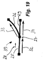
- Such a branch 39 can, however, in the situation according to Figure 16 cannot be correctly recognized by the processing unit 12 since the route elements 25, 29 in Figure 19 are not separated from one another by a connection point 27, but instead a single straight, continuous route element 25 is present.
- connection point 27 of the route element 26 has no suitable connection point.
- the distance determining means 36 again calculates the distance of this connection point 27 of the route element 26 from the route element 25 by orthogonal projection of the point onto all route elements 25, 26, 29 of the CAD route data 9.
- a fifth distance threshold value which can be selected, for example, equal to the first distance threshold value or second distance threshold value or a distance threshold value below the first distance threshold value
- the processing unit 12 assumes that the connection point 27 lies on the route element 25.
- tangents 32, 33, 34 to the connection points 27 of the route elements 25, 26 are calculated. If these are the same or are within a predetermined angular range, there is branching. An intersection, on the other hand, has very different tangents.
- a subdivision means is formed in the processing unit 12, with which a further connection point 27 can be formed in a route element 25, 26, 29 between the associated connection points 27, 30, as a result of which the processed route element 25, 26, 29 is divided into two route elements and separated.
- this additional connection point is inserted as division point 41 such that its position coincides with the connection point 27 of the route element 26.
- Figure 19 explains how the direction of travel information 28 is transmitted at a branch point 39 from a route element 25 to the following route elements 26 and 29.
- the direction of travel information 28 for the route element 25, that is to say the route element arranged first in the direction of travel of the conveying route 2 defines a direction of travel which is oriented parallel (in the same direction) or antiparallel (in the opposite direction) to the tangent 32 of the route element 25.
- the travel direction information of the route elements 26 and 29 becomes the same chosen that the associated direction of travel are aligned parallel, ie in the same direction, to the respective tangents 33 and 34, respectively.
- the direction of travel information of the route elements 26, 29 is determined in such a way that there is a direction of travel which runs antiparallel, that is to say in the opposite direction, to the tangents 33 and 34, respectively.
- connection point 27 of the route element 26 lies within a fifth distance threshold value to the route element 25 and at the same time the connection point 27 of the route element 26 lies outside a sixth distance threshold value to the connection points 27 of the route element 25.
- the fifth distance threshold value can be selected to be equal to the first distance threshold value or smaller than the first distance threshold value or otherwise.
- the sixth distance threshold value can be selected equal to a fraction of a typical length of a route element, for example equal to half or two thirds of this length.
- a division point 41 is inserted in the route element 25, which marks the transition of a route element part formed by the division from the other, remaining route element part. From this division point 41, two connection points are automatically formed, each of which is assigned to one of the new route elements created from route element 25.
- the CAD route data 9 are thus automatically converted by the processing unit 12 into a route layout 43 of the conveyor route 2, wherein the route elements 43 link the route elements 25, 26, 29 of the conveyor route 2 at connection points 27, 30 and with direction of travel information 28 are provided in such a way that the conveyor section 2 is simulated in the virtual reality 13.
- This route layout 43 is now output via the data output 16 into the storage means 23 and is made available there for further processing in the form of control data 15.
- the route layout 43 can be fed to a material closing computer 17 in the form of control data 15 tailored to the material flow computer 17 or adapted to the material flow computer 17, in which the material flow in the conveyor line 2 can be calculated or simulated.
- the route layout 43 or at least a relevant part thereof is converted in a manner known per se into a data format which is matched to the material flow computer 17.
- the control data 15 then represent the information portion of the route layout 43 required for the material flow computer 17 in this data format.
- the route layout 43 can be supplied via the interface 21 to a control unit 18 in the form of control data 15 which is tailored to the control unit 18 or adapted to the control unit 18 and with which the production system 1 can be controlled in accordance with the data from the route layout 43.
- the route layout 43 is converted in a manner known per se into control data 15 for the control unit 18.
- the route layout 43 can alternatively or additionally be transmitted via the interface 21 to a simulation unit 19 in the form of control data 15 tailored to the simulation unit 19 or adapted to the simulation unit 19, in which sequence processes of the production plant 1 can be simulated with the data of the route layout 43.
- the route layout 43 is converted in a manner known per se into control data 15 for the simulation unit 19.
- the route layout 43 can alternatively or additionally be transmitted via the interface 21 to a parts list / calculation unit, in which, for example, parts lists for the conveyor line 2 to be set up and / or calculations for the conveyor line 2 with the data of the line layout 43, in the form of from Route layout 43 in control data 15 generated in a manner known per se are automatically calculated.
- the control data 15 can generally be transmitted as parameters.
- the invention thus also enables an inventive method in which the route layout 43 is transferred at least in parameter form or completely to a vehicle controller of a transport unit 3 traveling in the conveyor route 2.
- the user can, for example, select the menu item "Device parameterization” for the corresponding part of production plant 1 (for example the transport units "AGV_01" to "AGV_05" or for the part "SC").
- the vehicle controller can be set up to control the transport unit 3 by comparing an actual position of the transport unit 3 with a target position described by the route layout 43.
- the vehicle controller can be set up for a corresponding evaluation of the route layout 43, for example for the extraction of target positions from the route layout 43.
- the route layout 43 and / or the or an at least locally one-dimensional, computer-readable description of the logical conveying flow is transferred to a control unit 18 and is used or provided for controlling transport units 3 of the production system 1.
- the advantage here is that manual steps during commissioning can be avoided and / or reduced.
- route layout 43 an error check is carried out in processing unit 12, in which it is checked for each route element 25, 26, 29 whether the assigned travel direction information 28 is compatible with one another and with the linkage. For example, it can be checked here whether a discharge switch or rather a feed switch should actually be provided at a certain point, since the two route elements differ in the direction of travel information.
- a route layout 43 is generated and data of the route layout 43 to the at least one transport unit 3 and / or the control unit 18 are transferred. Manual, time-consuming intermediate steps are unnecessary.
- the route layout 43 is transferred to a vehicle controller of the transport unit 3.
- the data of the route layout 43 can simply be transmitted in parameter form.
- the vehicle controller is set up to control the transport unit 3 by comparing an actual position of the transport unit 3 with a target position described by the route layout 43. In this case, no guidance is required, but the guidance results from the data of the route layout 43.
- the route layout 43 is converted into a locally one-dimensional, computer-readable description of the logical conveying flow. This description is then transferred to the control unit 18.
- the computer-readable description represents a set of control data 15.
- the transport units 3 of the production plant 1 are controlled on the basis of these control data.
Landscapes
- Engineering & Computer Science (AREA)
- General Engineering & Computer Science (AREA)
- Manufacturing & Machinery (AREA)
- Quality & Reliability (AREA)
- Physics & Mathematics (AREA)
- General Physics & Mathematics (AREA)
- Automation & Control Theory (AREA)
- General Factory Administration (AREA)
Description
Die Erfindung betrifft ein Verfahren zum computergestützten Nachbilden einer Produktionsanlage, ein Verfahren zur Inbetriebnahme einer Produktionsanlage, eine Konfigurationseinrichtung und eine Produktionsanlage.The invention relates to a method for computer-aided reproduction of a production system, a method for starting up a production system, a configuration device and a production system.
Derartige Verfahren sind bekannt und werden eingesetzt, um den Betriebsablauf auf einer Anlage vor der eigentlichen Inbetriebnahme zu überprüfen. Auf diese Weise können Fehler, die bis zum Produktionsstart eliminiert werden müssen, im Vorfeld erkannt und beseitigt werden.Such methods are known and are used to check the operational sequence on a system before the actual commissioning. In this way, errors that must be eliminated before the start of production can be identified and eliminated in advance.
Aus
Aus
Der Erfindung liegt die Aufgabe zugrunde, die ingenieursmäßige Projektierung und/oder Inbetriebnahme von Produktionsanlagen zu automatisieren.The invention has for its object to automate the engineering design and / or commissioning of production facilities.
Diese Aufgabe wird erfindungsgemäß bei einem Verfahren durch die Merkmale des Anspruchs 1, bei einem Verfahren zur Inbetriebnahme einer Produktionsanlage durch die Merkmale von Anspruch 14, bei einer Konfigurationsvorrichtung durch die Merkmale des Anspruchs 15 und bei einer Produktionsanlage durch die Merkmale des Anspruchs 20 gelöst.This object is achieved according to the invention in a method by the features of
Wichtige Merkmale der Erfindung eines Verfahrens zum computergestützten Nachbilden einer Produktionsanlage, wobei die Produktionsanlage wenigstens eine Förderstrecke aufweist, sind, dass CAD-Streckendaten in eine Verarbeitungseinheit eingelesen werden und dass aus den CAD-Streckendaten ein Streckenlayout computerimplementiert generiert wird, welches einen logischen Förderfluss der Förderstrecke computerlesbar beschreibt. Von Vorteil ist dabei, dass mit dem Streckenlayout Daten vorliegen, die zu einer computergestützten Simulation, Anzeige, Überwachung und/oder Ansteuerung eines Fahrbetriebs auf der Förderstrecke und/oder eines Förderflusses auf der Förderstrecke weiterverwendbar sind. Somit ermöglicht die Erfindung, ein zur Parametrierung, Überprüfung, Simulation, Ansteuerung und/oder Modifikation von Bewegungsabläufen verwendbares Streckenlayout bereitzustellen. Die Projektierung und die Inbetriebnahme einer Produktionsanlage sind somit erheblich vereinfachbar. Zusätzlich ist hierbei vorgesehen, dass die CAD-Streckendaten fehlerbehaftet sind, dass ein Regelwerk, beispielsweise das weiter unten erwähnte Regelwerk, Regeln einer Fehlerkorrektur der fehlerbehafteten CAD-Streckendaten aufweist und dass diese Regeln auf die CAD-Streckenddaten zur Erzeugung eines Streckenlayouts, beispielsweise des bereits erwähnten Streckenlayouts, computerimplementiert angewendet werden. Die CAD-Streckendaten können beispielsweise fehlerbehaftet sein, weil die CAD-Modelle nicht mit der erforderlichen Genauigkeit erstellt wurden. Die Hinterlegung von Regeln hat den Vorteil, dass die CAD-Streckendaten in einem automatisierten Verfahren zur Verwendung in einer nachgelagerten Ansteuerung aufbereitbar sind.Important features of the invention of a method for computer-aided replication of a production system, the production system having at least one conveyor route, are that CAD route data are read into a processing unit and that a route layout is generated in a computer-implemented manner from the CAD route data, which logic route conveying flow of the conveyor route describes computer-readable. The advantage here is that the route layout contains data which can be used for a computer-aided simulation, display, monitoring and / or control of a driving operation on the conveyor route and / or a conveyor flow on the conveyor route. The invention thus makes it possible to provide a route layout that can be used for parameterization, checking, simulation, control and / or modification of motion sequences. The project planning and commissioning of a production plant can thus be considerably simplified. In addition, it is provided here that the CAD route data is error-prone, that a set of rules, for example the set of rules mentioned below, has rules for error correction of the error-prone CAD route data and that these rules apply to the CAD route end data for generating a route layout, for example the one already mentioned route layouts can be applied in a computer-implemented way. The CAD route data can be faulty, for example, because the CAD models were not created with the required accuracy. The storage of rules has the advantage that the CAD route data can be prepared in an automated process for use in a downstream control.
Bei einer Ausgestaltung der Erfindung kann vorgesehen sein, dass zur Generierung des Streckenlayouts im logischen Förderfluss aufeinanderfolgende Streckenelemente der CAD-Streckendaten logisch verknüpft werden. Von Vorteil ist dabei, dass ein Zusammenhang zwischen den Streckenelementen ermittelbar und definierbar ist. Somit ist in computerlesbarer Weise eine Abfolge der Streckenelemente im logischen Förderfluss definierbar. Besonders günstig ist es, wenn die Streckenelemente hierbei an Verbindungspunkten, vorzugsweise an allen Verbindungspunkten jedes Streckenelements, verknüpft werden. So lassen sich auf einfache Weise zusammenhängende Abschnitte des Streckenlayouts bilden, die einen logischen Förderfluss beschreiben oder vorgeben.In one embodiment of the invention, it can be provided that successive route elements of the CAD route data are logically linked in order to generate the route layout in the logical conveying flow. The advantage here is that a relationship between the route elements can be determined and defined. A sequence of the route elements in the logical conveying flow can thus be defined in a computer-readable manner. It is particularly favorable if the route elements here at connection points, preferably at all connection points of each route element, be linked. In this way, it is easy to form coherent sections of the route layout that describe or specify a logical flow of funding.
Bei einer Ausgestaltung der Erfindung kann vorgesehen sein, dass das Streckenlayout zwei- oder dreidimensionale Positionsangaben zu Streckenelementen des Streckenlayouts enthält. Von Vorteil ist dabei, dass das Streckenlayout zur Regelung einer Ist-Position von Transporteinheiten auf eine Soll-Position verwendbar ist. Hierzu kann die jeweilige Transporteinheit zur Extraktion von Soll-Positionen für die eigene, vorzugsweise gemessene oder ermittelte, Ist-Position eingerichtet sein.In one embodiment of the invention, it can be provided that the route layout contains two- or three-dimensional position information on route elements of the route layout. The advantage here is that the route layout can be used to regulate an actual position of transport units to a target position. For this purpose, the respective transport unit can be set up to extract target positions for its own, preferably measured or ascertained, actual position.
Bei einer Ausgestaltung der Erfindung kann vorgesehen sein, dass aus dem Streckenlayout eine zumindest lokal eindimensionale, computerlesbare Beschreibung des logischen Förderflusses abgeleitet wird. Somit ist eine intrinsische Beschreibung der Förderstrecke, also ohne Bezug auf die Lage, den Verlauf und/oder die Einbettung der Förderstrecke im Raum, bereitstellbar und/oder verwendbar. Bei einer lokal eindimensionalen Beschreibung sind Verzweigungen und/oder Weichen zulässig, und die Beschreibung ist jenseits der Verzweigungen und/oder Weichen eindimensional. Eine Abfolge im logischen Förderfluss ist somit mit minimalem Datenaufwand beschreibbar oder vorgebbar.In one embodiment of the invention, it can be provided that an at least locally one-dimensional, computer-readable description of the logical conveying flow is derived from the route layout. An intrinsic description of the conveyor line, that is to say without reference to the position, the course and / or the embedding of the conveyor line in space, can thus be provided and / or used. In the case of a locally one-dimensional description, branches and / or switches are permissible, and the description is one-dimensional beyond the branches and / or switches. A sequence in the logical flow of funding can thus be described or specified with minimal data expenditure.
Bei einer Ausgestaltung der Erfindung kann vorgesehen sein, dass das Streckenlayout zumindest in Parameterform an eine Fahrzeugsteuerung einer in der Förderstrecke fahrenden Transporteinheit übergeben wird. Von Vorteil ist dabei, dass die Transporteinheiten automatisiert parametrierbar, einrichtbar und/oder in Betrieb nehmbar sind. Manuelle Bearbeitungsschritte sind hierbei weitestgehend oder sogar vollständig verzichtbar.In one embodiment of the invention, it can be provided that the route layout is transferred, at least in parameter form, to a vehicle controller of a transport unit traveling in the conveyor route. The advantage here is that the transport units can be automatically parameterized, set up and / or put into operation. Manual processing steps are largely or even completely dispensable.
Hierbei kann vorgesehen sein, dass die Fahrzeugsteuerung zur Steuerung der Transporteinheit anhand eines Vergleichs einer Ist-Position der Transporteinheit mit einer durch das Streckenlayout beschriebenen Soll-Position eingerichtet ist. Von Vorteil ist dabei, dass die zweidimensionalen Positionsinformationen des Streckenlayouts, die aus den CAD-Streckendaten abgeleitet wurden, zur Spurführung verwendbar sind.It can be provided here that the vehicle controller is set up to control the transport unit on the basis of a comparison of an actual position of the transport unit with a target position described by the route layout. The advantage here is that the two-dimensional position information of the route layout, which was derived from the CAD route data, can be used for tracking.
Bei einer Ausgestaltung der Erifnung kann vorgesehen sein, dass das Streckenlayout und/oder die oder eine zumindest lokal eindimensionale, computerlesbare Beschreibung des logischen Förderflusses an eine Steuerungseinheit übergeben und zu einer Ansteuerung von Transporteinheiten der Produktionsanlage verwendet oder bereitgestellt wird. Von Vorteil ist dabei, dass eine manuelle Inbetriebnahme der Produktionsanlage verzichtbar ist.In one embodiment of the registration, it can be provided that the route layout and / or the or at least locally one-dimensional, computer-readable description of the logical conveying flow is transferred to a control unit and used or provided to control transport units of the production plant. The advantage here is that manual commissioning of the production system is not necessary.
Alternativ oder zusätzlich sind wichtige Merkmale der Erfindung eines Verfahrens zum computergestützten Nachbilden einer Produktionsanlage, wobei die Produktionsanlage wenigstens eine Förderstrecke aufweist, dass CAD-Streckendaten in eine Verarbeitungseinheit eingelesen werden, dass die CAD-Streckendaten in einer virtuellen Realität automatisiert dargestellt werden und dass Ansteuerungsdaten an einer für wenigstens ein Element aus der Gruppe von Materialflussrechner, übergeordnete Steuerungseinheit, externe Simulationseinheit und Stücklisten-/Kalkulationseinheit ausgebildete Schnittstelle automatisiert bereitgestellt werden. Von Vorteil ist dabei, dass die Produktionsanlage in einer virtuellen Realität nachgebildet werden kann. Dies ermöglicht es, die Steuerungsprogramme der Produktionsanlage entsprechend zu parametrieren.As an alternative or in addition, important features of the invention are a method for computer-aided replication of a production system, the production system having at least one conveyor line, CAD route data being read into a processing unit, the CAD route data being displayed automatically in a virtual reality and control data being triggered an interface designed for at least one element from the group of material flow computer, superordinate control unit, external simulation unit and parts list / calculation unit is provided automatically. The advantage here is that the production system can be simulated in a virtual reality. This enables the control programs of the production plant to be parameterized accordingly.
Wichtige Merkmale der Erfindung eines Verfahrens zum computergestützten Nachbilden einer Produktionsanlage, insbesondere wie zuvor beschrieben und/oder nach Anspruch 1, wobei die Produktionsanlage wenigstens eine Förderstrecke aufweist, sind alternativ oder zusätzlich, dass CAD-Streckendaten in eine Verarbeitungseinheit eingelesen werden, wobei die CAD-Streckendaten zumindest Streckenelemente umfassen, aus denen die Förderstrecke gebildet ist, und dass die Streckenelemente mit einem Regelwerk automatisiert zu einem Streckenlayout verknüpft und zu einer computergestützten Nachbildung der Förderstrecke bereitgestellt werden. Von Vorteil ist dabei, dass das Streckenlayout automatisiert gewinnbar ist. Somit kann der insgesamt benötigt Arbeitsaufwand bis zum Start der Anlagensimulation reduziert werden. Auch sind so Zuordnungsfehler beim Erstellen des Streckenlayouts vermeidbar.Important features of the invention of a method for computer-aided reproduction of a production system, in particular as described above and / or according to
Die Verarbeitungseinheit ist bei der Erfindung bevorzugt als Datenverarbeitungseinheit oder auf sonstige Weise zum automatisierten Ablauf ausgebildet.In the case of the invention, the processing unit is preferably designed as a data processing unit or in some other way for the automated process.
Zur automatischen Erzeugung des Streckenlayouts aus den CAD-Streckendaten sind computergestützt auswertbare Regeln hinterlegt, die auf die CAD-Streckendaten angewendet werden. Die Begriffe erstes Streckenelement, zweites Streckenelement, weiteres Streckenelement sind in dieser Beschreibung als Platzhalter in den jeweils beschriebenen Regeln zu verstehen.For the automatic generation of the route layout from the CAD route data, computer-supported evaluable rules are stored which are applied to the CAD route data. The terms first route element, second route element, further In this description, route elements are to be understood as placeholders in the rules described in each case.
Bei einer vorteilhaften Ausgestaltung kann vorgesehen sein, dass ein erster Verbindungspunkt eines ersten Streckenelements mit einem zweiten Verbindungspunkt eines zweiten Streckenelements automatisiert verknüpft wird, wenn sich der erste Verbindungspunkt des ersten Streckenelements innerhalb eines ersten Abstandschwellwerts zu dem zweiten Verbindungspunkt des zweiten Streckenelements befindet. Von Vorteil ist dabei, dass in der CAD-Zeichnung separate Streckenelemente automatisiert als zueinander in der Förderstrecke benachbart erkennbar sind und erkannt werden. Bevorzugt ist der Abstandsschwellwert so gewählt, dass zufällige Lücken in der Förderstrecke aufgrund von Zeichnungsungenauigkeiten in den CAD-Streckendaten von absichtlich gelassenen Lücken, über welche keine Förderstrecke verläuft, automatisiert unterscheidbar sind. Beispielsweise kann der erste Abstandsschwellwert einen Bruchteil, beispielsweise weniger als die Hälfte oder weniger als ein Zehntel, einer durchschnittlichen oder minimalen Länge der Streckenelemente betragen.In an advantageous embodiment, it can be provided that a first connection point of a first route element is automatically linked to a second connection point of a second route element if the first connection point of the first route element is within a first distance threshold to the second connection point of the second route element. The advantage here is that in the CAD drawing separate route elements are automatically recognized and recognized as being adjacent to one another in the conveyor route. The distance threshold value is preferably selected such that random gaps in the conveyor line can be automatically differentiated from deliberately left gaps, over which no conveyor line runs, due to drawing inaccuracies in the CAD route data. For example, the first distance threshold value can be a fraction, for example less than half or less than a tenth, of an average or minimum length of the route elements.
Bei einer vorteilhaften Ausgestaltung kann vorgesehen sein, dass ein erster Verbindungspunkt eines ersten Streckenelements mit einem zweiten Verbindungspunkt eines zweiten Streckenelements verknüpft wird, wenn sich der erste Verbindungspunkt des ersten Streckenelements innerhalb eines zweiten Abstandschwellwerts zu dem zweiten Verbindungspunkt des zweiten Streckenelements befindet und wenn sich kein dritter Verbindungspunkt eines dritten Streckenelements innerhalb des oder eines ersten Abstandsschwellwerts zu dem ersten und/oder zweiten Verbindungspunkt befindet. Von Vorteil ist dabei, dass unverzweigte Verbindungen, die zeichnungsbedingt eine Lücke aufweisen, von Verzweigungen automatisiert unterscheidbar sind.In an advantageous embodiment, it can be provided that a first connection point of a first route element is linked to a second connection point of a second route element if the first connection point of the first route element is within a second distance threshold to the second connection point of the second route element and if there is no third Connection point of a third route element is located within the or a first distance threshold value to the first and / or second connection point. From The advantage here is that unbranched connections that have a gap due to the drawing can be automatically distinguished from branches.
Somit kann für die Streckenelemente der CAD-Streckendaten automatisiert und vorzugsweise rekursiv oder nacheinander geprüft werden, ob sich ein Verbindungspunkt eines Streckenelements innerhalb eines ersten Abstandschwellwerts zu einem Verbindungspunkt eines weiteren Streckenelements befindet.It can thus be automated and preferably recursively or successively checked for the route elements of the CAD route data whether a connection point of a route element is within a first distance threshold value to a connection point of a further route element.
Es kann vorgesehen sein, dass Weichen aus den CAD-Streckendaten entfernt werden, bevor das Streckenlayout erstellt wird. Dies hat den Vorteil, dass eine Erkennung und Unterscheidung der unterschiedlichen Weichentypen, die auftreten können, verzichtbar ist.It can be provided that switches are removed from the CAD route data before the route layout is created. This has the advantage that it is not necessary to recognize and differentiate between the different types of switches that can occur.
Alternativ oder unterstützend kann vorgesehen sein, dass Weichentypen mit einem Merkmals- und/oder Mustererkennungsalgorithmus identifiziert und/oder klassifiziert werden. Die ermöglicht eine nochmals verbesserte Treffsicherheit bei der automatisierten Einrichtung von Verzweigungspunkten im Streckenlayout.As an alternative or in support, it can be provided that switch types are identified and / or classified using a feature and / or pattern recognition algorithm. This enables a further improved accuracy in the automated setup of branch points in the route layout.
Bei einer vorteilhaften Ausgestaltung kann vorgesehen sein, dass ein Weichenelement oder ein Verzweigungselement in das Streckenlayout automatisiert eingefügt wird, wenn ein Verbindungspunkt eines ersten Streckenelements mit jeweils einem Verbindungspunkt von wenigstens zwei weiteren Streckenelementen verknüpft ist. Durch die Einfügung werden die beteiligten Verbindungspunkte somit indirekt (über das eingefügte Element) verknüpft. Von Vorteil ist dabei, dass Verzweigungen automatisiert erkannt und in das Streckenlayout aufgenommen werden können, ohne dass eine aufwändige Merkmals- oder Mustererkennung erforderlich wäre. Generell unterscheidet sich ein Verzweigungselement von einem Weichenelement dadurch, dass bei einem Verzweigungselement dauerhaft wenigstens drei Streckenelemente verbunden sind, während bei einem Weichenelement durch unterschiedliche Zustände unterschiedliche Verbindungen einzelner Streckenelemente miteinander herstellbar sind.In an advantageous embodiment, it can be provided that a switch element or a branching element is automatically inserted into the route layout if a connection point of a first route element is linked to a connection point of at least two further route elements. The connection points involved are thus linked indirectly (via the inserted element). The advantage here is that branches can be automatically recognized and included in the route layout without the need for complex feature or pattern recognition. In general, a branching element differs from a switch element in that in the case of a branching element at least three route elements are permanently connected, while in the case of a switch element different connections of individual route elements can be produced by different states.
Bei einer vorteilhaften Ausgestaltung kann vorgesehen sein, dass für die Streckenelemente der CAD-Streckendaten, die wenigstens einen Verbindungspunkt aufweisen, zu dem sich kein Verbindungspunkt eines weiteren Streckenelements innerhalb des oder eines (ersten) Abstandsschwellwerts befindet, automatisiert geprüft wird, ob sich dieser Verbindungspunkt des Streckenelements innerhalb eines zweiten Abstandschwellwerts zu einem Verbindungspunkt eines weiteren Streckenelements befindet. Somit sind Verzweigungen von zufälligen Lücken automatisiert unterscheidbar. Bevorzugt ist der zweite Abstandsschwellwert größer als der erste Abstandsschwellwert gewählt. Befindet sich innerhalb des zweiten Abstandsschwellwertes nur ein einziger weiterer Verbindungspunkt, so kann vorgesehen sein, dass eine ungewollte Lücke in der CAD-Zeichnung automatisch erkannt und dieser weitere Verbindungspunkt mit dem zuvor genannten Verbindungspunkt automatisch verknüpft wird.In an advantageous embodiment, it can be provided that for the route elements of the CAD route data which have at least one connection point to which there is no connection point of a further route element within the or a (first) distance threshold value, an automatic check is made as to whether this connection point is located of the route element is located within a second distance threshold value to a connection point of a further route element. In this way, branches can be automatically distinguished from random gaps. The second distance threshold value is preferably selected to be greater than the first distance threshold value. If there is only a single further connection point within the second distance threshold value, it can be provided that an unwanted gap in the CAD drawing is automatically recognized and this further connection point is automatically linked to the previously mentioned connection point.
Bei einer vorteilhaften Ausgestaltung kann vorgesehen sein, dass zu einem ersten Verbindungspunkt eines ersten Streckenelements, zu welchem innerhalb des zweiten Abstandsschwellwertes kein Verbindungspunkt eines weiteren Streckenelements auffindbar ist, automatisiert geprüft wird, welches Streckenelement innerhalb eines dritten Abstandschwellwerts zu dem ersten Verbindungspunkt liegt. Von Vorteil ist dabei, dass auch größere Lücken im Streckenverlauf in den CAD-Streckendaten, die sich beispielsweise nach dem Löschen eines Weichenelements ergeben haben, verarbeitbar sind. Vorzugsweise ist der dritte Abstandsschwellwert größer als der zweite Abstandsschwellwert und besonders bevorzugt so groß gewählt, dass alle auftretenden oder verwendbaren Weichenelemente eine Ausdehnung aufweisen, die kleiner als der dritte Abstandsschwellwert ist. Somit sind die Verbindungspunkte, die über ein Verzweigungs- oder Weichenelement verbunden sind, automatisch identifizierbar.In an advantageous embodiment, it can be provided that for a first connection point of a first route element to which no connection point of a further route element can be found within the second distance threshold value, which route element lies within a third distance threshold value to the first connection point. The advantage here is that even larger gaps in the course of the route in the CAD route data, which resulted, for example, after deleting a switch element, can be processed. The third distance threshold value is preferably greater than the second distance threshold value and particularly preferably chosen to be so large that all switch elements that occur or can be used have an extent that is smaller than the third distance threshold value. The connection points which are connected via a branching or switch element can thus be identified automatically.
Bei einer vorteilhaften Ausgestaltung kann vorgesehen sein, dass ein erster Verbindungspunkt eines ersten Streckenelements mit einem zweiten Verbindungspunkt eines zweiten Streckenelements verknüpft wird, wenn der erste Verbindungspunkt innerhalb eines oder des vierten Abstandschwellwertes zu dem zweiten Streckenelement und der zweite Verbindungspunkt innerhalb des vierten Abstandschwellwertes zu dem ersten Streckenelement liegt. Somit ist ein automatisiertes Verfahren zur Verbindung von Streckenelementen ausführbar, welches seitlich in Bezug auf eine Verlaufsrichtung der Förderstrecke zueinander versetzte Streckenelemente automatisch identifiziert und verbindet. Der vierte Abstandsschwellwert kann beispielsweise gleich dem zweiten Abstandsschwellwert gewählt sein.In an advantageous embodiment it can be provided that a first connection point of a first route element is linked to a second connection point of a second route element if the first connection point within one or the fourth distance threshold value to the second route element and the second connection point within the fourth distance threshold value to the first Line element lies. An automated method for connecting route elements can thus be carried out, which automatically identifies and connects route elements offset laterally with respect to one another in the direction of travel of the conveyor route. The fourth distance threshold value can, for example, be chosen to be equal to the second distance threshold value.
Bei einer vorteilhaften Ausgestaltung kann vorgesehen sein, dass ein Parameter eines Streckenelements, bei welchem ein erster Verbindungspunkt mit genau einem zweiten Verbindungspunkt eines weiteren Streckenelements verknüpft ist, verändert wird, bis der erste Verbindungspunkt innerhalb des ersten Abstandschwellwertes zu dem zweiten Verbindungspunkt liegt. Von Vorteil ist dabei, dass zufällige Überlappungen von Streckenelementen in den CAD-Streckendaten im Streckenlayout automatisch beseitigbar sind.In an advantageous embodiment, it can be provided that a parameter of a route element in which a first connection point is linked to exactly one second connection point of a further route element is changed until the first connection point lies within the first distance threshold value from the second connection point. The advantage here is that random overlaps of route elements in the CAD route data in the route layout can be automatically eliminated.
Bei einer vorteilhaften Ausgestaltung kann vorgesehen sein, dass ein erstes Streckenelement an einem Teilungspunkt in zwei weitere Streckenelemente unterteilt wird, wenn ein Verbindungspunkt eines zweiten Streckenelements innerhalb eines fünften Abstandschwellwertes zu dem ersten Streckenelement aber außerhalb eines sechsten Abstandsschwellwertes zu den Verbindungspunkten des ersten Streckenelements liegt, wobei jedes der zwei weiteren Streckenelemente einen Verbindungspunkt von dem ersten Streckenelement erhält und einen weiteren Verbindungspunkt an dem Teilungspunkt erhält, wobei diese weiteren Verbindungspunkte miteinander verknüpft werden. Von Vorteil ist dabei, dass fehlende Verzweigungspunkte an Stellen, an denen ein zweites Streckenelemente auf ein erstes Streckenelement stößt, automatisch erzeugbar sind. Der fünfte Abstandsschwellwert kann beispielsweise gleich dem ersten oder zweiten Abstandsschwellwert gewählt sein. Der sechste Abstandsschwellwert kann beispielsweise gleich dem zweiten oder dritten Abstandsschwellwert gewählt sein. Der sechste Abstandsschwellwert kann ein Bruchteil, beispielsweise die Hälfte oder ein Drittel, eine typischen, durchschnittlichen oder mininmalen Abmessung der Streckenelemente betragen. Somit ist leicht automatisch erkennbar, wenn ein Verbindungspunkt des zweiten Streckenelements an dem ersten Streckenelement in etwa mittig zwischen dessen Verbindungspunkten liegt.In an advantageous embodiment it can be provided that a first route element at a division point is divided into two further route elements if a connection point of a second route element lies within a fifth distance threshold value to the first route element but outside a sixth distance threshold value to the connection points of the first route element, whereby each of the two further route elements receives a connection point from the first route element and receives a further connection point at the division point, these further connection points being linked to one another. The advantage here is that missing branching points can be automatically generated at points where a second route element encounters a first route element. The fifth distance threshold value can, for example, be selected to be equal to the first or second distance threshold value. The sixth distance threshold value can, for example, be selected to be equal to the second or third distance threshold value. The sixth distance threshold can be a fraction, for example half or a third, of a typical, average or minimum dimension of the route elements. It is therefore easy to automatically recognize when a connection point of the second route element lies approximately centrally between the connection points on the first route element.
Bei einer vorteilhaften Ausgestaltung kann vorgesehen sein, dass mit einer Fahrtrichtungsinformation eines Streckenelements ein Verbindungspunkt dieses Streckenelements als ein Startpunkt und ein weiterer Verbindungspunkt dieses Streckenelements als ein Endpunkt charakterisiert wird. Von Vorteil ist dabei, dass automatische Konsistenzprüfungen durchführbar sind. Beispielsweise kann geprüft werden, ob im Streckenlayout Startpunkte eines Streckenelements mit Endpunkten des benachbarten Streckenelements verbunden sind.In an advantageous embodiment, it can be provided that a connection point of this route element is characterized as a starting point and a further connection point of this route element as an end point using travel direction information of a route element. The advantage here is that automatic consistency checks can be carried out. For example, it can be checked whether start points of a route element are connected to end points of the adjacent route element in the route layout.
Bei einer vorteilhaften Ausgestaltung kann vorgesehen sein, dass zu einem ersten Streckenelement eine Fahrtrichtungsinformation aus einer Fahrtrichtungsinformation eines zweiten Streckenelements derart abgeleitet wird, dass ein Startpunkt mit einem Endpunkt verknüpft wird. Von Vorteil ist dabei, dass fehlende Fahrtrichtungsinformationen automatisch gewinnbar oder automatisch rekonstruierbar sind.In an advantageous embodiment, it can be provided that direction information for a first route element is derived from direction information of a second route element such that a starting point is linked to an end point. The advantage here is that missing travel direction information can be obtained automatically or can be reconstructed automatically.
Bei einer vorteilhaften Ausgestaltung kann vorgesehen sein, dass an einem Verbindungspunkt eines Streckenelements eine Tangente an dieses Streckenelement berechnet wird. Von Vorteil ist dabei, dass Streckenelemente, die fehlerhaft in den CAD-Streckendaten beabstandet zu einem Streckenelement angeordnet sind, identifizierbar sind. Auch kann anhand der berechneten Tangente zwischen mehreren Verbindungspunkten anderer Streckelemente ein Verbindungspunkt zur Verknüpfung ausgewählt werden.In an advantageous embodiment, it can be provided that a tangent to this route element is calculated at a connection point of a route element. It is advantageous here that route elements that are incorrectly spaced from a route element in the CAD route data can be identified. A connection point for linking can also be selected on the basis of the calculated tangent between several connection points of other stretching elements.
Bei einer vorteilhaften Ausgestaltung kann vorgesehen sein, dass ein Verzweigungs-, Weichen- und/oder Kreuzungselement automatisch anhand der berechneten Tangenten der beteiligten Verbindungspunkte ausgewählt wird/werden. Von Vorteil ist dabei, dass Verzweigungspunkte mit geringer Fehlerquote im Streckenlayout an den richtigen Positionen erzeugbar sind. Die Erfindung macht sich zunutze, dass Weichen und Verzweigungen durch die relative Lage der Tangenten an den Verbindungspunkten für die automatische Verarbeitung beschreibbar und/oder klassifizierbar sind. Hierbei können die Tangente an einem Verbindungspunkt durch Analyse des Verlaufs des zugehörigen Streckenelements in unmittelbarer Nachbarschaft zu dem Verbindungspunkt berechnet oder ermittelt werden.In an advantageous embodiment, it can be provided that a branching, switching and / or crossing element is / are selected automatically on the basis of the calculated tangents of the connecting points involved. The advantage here is that branching points with a low error rate in the route layout can be generated in the correct positions. The invention makes use of the fact that switches and branches can be described and / or classified for automatic processing by the relative position of the tangents at the connection points. Here, the tangent at a connection point can be calculated or determined by analyzing the course of the associated route element in the immediate vicinity of the connection point.
Bei einer vorteilhaften Ausgestaltung kann vorgesehen sein, dass zu dem Streckenlayout ein Steuerprogramm für auf der Förderstrecke verfahrbare Transporteinheiten erstellt und/oder ausgegeben wird. Von Vorteil ist dabei, dass eine Simulation des Anlagenbetriebs nach Abschluss der automatisierten Aufbereitung der CAD-Streckendaten ausführbar ist.In an advantageous embodiment, it can be provided that a control program for transport units that can be moved on the conveyor route is created and / or output for the route layout. The advantage here is that a simulation of the plant operation can be carried out after the automated preparation of the CAD route data has been completed.
Bei einer vorteilhaften Ausgestaltung kann vorgesehen sein, dass mit dem Steuerprogramm ein Materialflussrechner angesteuert wird. Von Vorteil ist dabei, dass ein Materialfluss auf der Produktionsanlage mit dem Ergebnis der Aufbereitung oder Verarbeitung der CAD-Streckendaten simulierbar oder im Betrieb steuerbar ist.In an advantageous embodiment, it can be provided that a material flow computer is controlled with the control program. The advantage here is that a material flow on the production system with the result of the preparation or processing of the CAD route data can be simulated or controlled during operation.
Bei einer vorteilhaften Ausgestaltung kann vorgesehen sein, dass mit dem Steuerprogramm eine Steuereinheit der Produktionsanlage und/oder eine Simulationseinheit, die zu einer Simulation eines Betriebsablaufs einer Förderstrecke mit Transporteinheiten eingerichtet ist, programmiert wird/werden. Von Vorteil ist dabei, dass die aufbereiteten CAD-Streckendaten weiterverarbeitbar sind.In an advantageous embodiment, it can be provided that the control program is used to program a control unit of the production system and / or a simulation unit which is set up to simulate an operating sequence of a conveyor line with transport units. The advantage here is that the prepared CAD route data can be further processed.
Bei einer vorteilhaften Ausgestaltung kann vorgesehen sein, dass die Streckenelemente aus den CAD-Streckendaten extrahiert und in einen separaten Layer geschrieben werden. Von Vorteil ist dabei, dass die Streckenelemente einzeln zur Erzeugung des Streckenlayouts verarbeitbar sind. Durch die Verwendung von Layern kann erreicht werden, dass die Positionsinformation der Streckenelemente bei der Extraktion aus den CAD-Streckendaten erhalten bleibt.In an advantageous embodiment, it can be provided that the route elements are extracted from the CAD route data and written into a separate layer. The advantage here is that the route elements can be processed individually to generate the route layout. The use of layers ensures that the position information of the route elements is retained when extracted from the CAD route data.
Bei einer vorteilhaften Ausgestaltung kann vorgesehen sein, dass eine Fehlerprüfung durchgeführt wird, in welcher für jedes Streckenelement eine eindeutige und/oder mit verknüpften Streckenelementen kompatible Zuordnung einer Fahrtrichtungsinformation geprüft wird. Somit sind Zuordnungsfehler automatisch erkennbar.In an advantageous embodiment, it can be provided that an error check is carried out in which a unique and / or compatible assignment of route information is checked for each route element. This means that assignment errors are automatically recognized.
Die Erfindung findet eine Anwendung bei einem Verfahren zur Inbetriebnahme einer Produktionsanlage mit wenigstens einer entlang einer Förderstrecke verfahrbaren Transporteinheit und eine Steuerungseinheit, wobei mit einem erfindungsgemäßen Verfahren zum Nachbilden einer Produktionsanlage, insbesondere wie zuvor beschreiben und/oder nach einem der auf ein Verfahren zum computergestützten Nachbilden einer Produktionsanlage gerichteten Ansprüche, ein Streckenlayout erzeugt und Daten des Streckenlayouts an die wenigstens eine Transporteinheit und/oder die Steuerungseinheit übergeben werden. Bevorzugt werden an die wenigstens eine Transporteinheit zweidimensionale Positionsangaben zu Streckenelementen des Streckenlayouts und an die Steuerungseinheit zumindest lokal eindimensionale Positionsangaben übermittelt. Von Vorteil ist dabei, dass minimal erforderlcihe Datenmengen übertragbar sind.The invention is used in a method for starting up a production system with at least one transport unit that can be moved along a conveyor line and a control unit, with a method according to the invention for emulating a production system, in particular as described above and / or according to one of the methods for computer-assisted emulation claims of a production plant, a route layout is generated and data of the route layout are transferred to the at least one transport unit and / or the control unit. Preferably, two-dimensional position information on route elements of the route layout are transmitted to the at least one transport unit and one-dimensional position information at least locally is transmitted to the control unit. The advantage here is that minimally required amounts of data can be transferred.
Wichtige Merkmale der Erfindung einer Konfigurationseinrichtung, mit einem Dateneingang zur Eingabe von CAD-Streckendaten und einem Datenausgang zur Ausgabe eines Streckenlayouts, sind, dass eine Verarbeitungseinheit zur Ausführung eines erfindungsgemäßen Verfahrens, insbesondere wie zuvor beschrieben und/oder nach einem der auf ein Verfahren zum Nachbilden einer Produktionsanlage gerichteten Ansprüche, ausgebildet und eingerichtet ist. Von Vorteil ist dabei, dass ein Mittel zur automatisierten, beispielsweise computergestützten, Abarbeitung des erfindungsgemäßen Verfahrens bereitstellbar ist. Beispielsweise kann die Konfigurationseinrichtung durch einen zur Ausführung des erfindungsgemäßen Verfahrens eingerichteten, insbesondere durch Konfiguration und/oder Programmierung eingerichteten, Computer gegeben sein.Important features of the invention of a configuration device, with a data input for entering CAD route data and a data output for outputting a route layout, are that a processing unit for executing a method according to the invention, in particular as described above and / or according to a of the claims directed to a method for emulating a production plant, is designed and set up. The advantage here is that a means for automated, for example computer-aided, processing of the method according to the invention can be provided. For example, the configuration device can be provided by a computer set up to carry out the method according to the invention, in particular set up by configuration and / or programming.
Bei einer vorteilhaften Ausgestaltung kann vorgesehen sein, dass die CAD-Streckendaten mit je zwei Verbindungspunkten versehene Streckenelemente aufweisen. Von Vorteil ist dabei, dass eine automatische Verknüpfung zusammengehörender Streckenelemente ausführbar ist. Vorzugsweise weisen die CAD-Streckendaten zusätzlich mit Metadaten, beispielsweise Fahrtrichtungsinformationen, Positionen von Wegmarken und dergleichen streckenbezogenen Metadaten, versehene Streckenelemente auf.In an advantageous embodiment, it can be provided that the CAD route data have route elements each provided with two connection points. The advantage here is that automatic linkage of route elements belonging together can be carried out. The CAD route data preferably also have route elements provided with metadata, for example travel direction information, positions of waymarks and the like route-related metadata.
Bei einer vorteilhaften Ausgestaltung kann vorgesehen sein, dass ein Abstandbestimmungsmittel zur Bestimmung eines Abstands zwischen einem Verbindungspunkt eines Streckenelements und einem weiteren Streckenelement ausgebildet ist. Von Vorteil ist dabei, dass zueinander benachbarte Streckenelemente identifizierbar sind. Beispielsweise kann das Abstandbestimmungsmittel zur Berechnung oder Ermittlung eines euklidischen Abstandes der Verbindungspunkt oder zur Berechnung oder Ermittlung eines Maximums einer Differenz der X-Koordinaten der Verbindungspunkte einerseits und einer Differenz der Y-Koordinaten der Verbindungspunkte andererseits ausgebildet sein.In an advantageous embodiment it can be provided that a distance determining means is designed to determine a distance between a connection point of a route element and a further route element. The advantage here is that adjacent route elements can be identified. For example, the distance determining means can be designed to calculate or determine a Euclidean distance of the connection point or to calculate or determine a maximum of a difference in the X coordinates of the connection points on the one hand and a difference in the Y coordinates of the connection points on the other hand.
Alternativ oder zusätzlich kann bei einer vorteilhaften Ausgestaltung vorgesehen sein, dass ein Vergleichsmittel zum Vergleich eines Abstands zwischen einem Verbindungspunkt eines Streckenelements und einem weiteren Streckenelement mit einem Abstandschwellwert ausgebildet ist. Beispielsweise kann dieser Abstandschwellwert wenigstens ein Element aus der Gruppe von erster, zweiter, dritter, vierter, fünfter und/oder sechster Abstandschwellwert sein. Von Vorteil ist dabei, dass ein automatisches Unterscheiden von zusammengehörigen Streckenelemente einerseits und nicht zusammengehörigen Streckenelementen andererseits ausführbar ist. Der Abstand kann zuvor mit dem beschriebenen Abstandbestimmungsmittel ermittelt worden sein.Alternatively or additionally, it can be provided in an advantageous embodiment that a comparison means is designed to compare a distance between a connection point of a route element and a further route element with a distance threshold. For example, this distance threshold can be at least one element from the group of first, second, third, fourth, fifth and / or sixth distance threshold. The advantage here is that an automatic distinction between associated route elements on the one hand and non-associated route elements on the other hand can be carried out. The distance can have been previously determined using the distance determining means described.
Bei einer vorteilhaften Ausgestaltung kann vorgesehen sein, dass ein Variationsmittel zur Variation eines Parameters eines Streckenelements eingerichtet ist. Diese Parameter können beispielsweise die Länge oder der Krümmungsradius oder dergleichen die Form eines Streckenelements beschreibende Maßangaben sein. Von Vorteil ist dabei, dass Darstellungsfehler in den CAD-Streckendaten automatisch korrigierbar sind. Bevorzugt wird das Streckenlayout korrigiert, bis Unstetigkeiten, also beispielsweise seitliche Versetzungen, und Knicke, also beispielsweise Unstetigkeiten in einer ersten Ableitung an den Verlauf der Förderstrecke, in der Förderstrecke oder den Förderstrecken eliminiert oder eliminierbar sind.In an advantageous embodiment, it can be provided that a variation means is set up to vary a parameter of a route element. These parameters can be, for example, the length or the radius of curvature or the like dimensions describing the shape of a route element. The advantage here is that display errors in the CAD route data can be corrected automatically. The route layout is preferably corrected until discontinuities, for example lateral displacements, and kinks, for example discontinuities in a first derivation of the course of the conveyor line, in the conveyor line or the conveyor lines can be eliminated or eliminated.
Bei einer vorteilhaften Ausgestaltung kann vorgesehen sein, dass ein Tangentenberechnungsmittel zur Berechnung einer Tangente in einem Verbindungspunkt eines Streckenelements an das Streckenelement ausgebildet ist. Von Vorteil ist dabei, dass ein Mittel zur Extrapolation des Streckenverlaufs ausgebildet sind, mit denen zueinander benachbarte, durch zufällige oder absichtlich gelassene Lücken voneinander beabstandete Streckenelemente als zusammengehörig identifzierbar und - beispielsweise über ein Weichenelement - verknüpfbar sind.In an advantageous embodiment it can be provided that a tangent calculation means is designed for calculating a tangent in a connection point of a route element to the route element. The advantage here is that a means for extrapolating the route is designed, with which adjacent route elements, spaced apart by random or deliberately left gaps, can be identified as belonging together and - for example via a switch element - can be linked.
Bei einer vorteilhaften Ausgestaltung kann vorgesehen sein, dass ein Unterteilungsmittel zur Teilung eines Streckenelements an einem Teilungspunkt in zwei weitere Streckenelemente ausgebildet ist. Von Vorteil ist dabei, dass Verzweigungspunkte, die in den CAD-Streckendaten fehlen, nachträglich rekonstruierbar sind.In an advantageous embodiment, it can be provided that a subdivision means is designed to divide a route element at a division point into two further route elements. The advantage here is that branching points that are missing in the CAD route data can be subsequently reconstructed.
Bei einer vorteilhaften Ausgestaltung kann vorgesehen sein, dass ein Zuweisungsmittel zur Zuweisung einer Fahrtrichtungsinformation zu einem Streckenelement ausgebildet ist. Von Vorteil ist dabei, dass das Streckenlayout mit einer Fahrtrichtungsinformation ausrüstbar ist, beispielsweise für eine Fehler- und/oder Plausibilitätsprüfung.In an advantageous embodiment, it can be provided that an assignment means is designed to assign travel direction information to a route element. The advantage here is that the route layout can be equipped with travel direction information, for example for an error and / or plausibility check.
Bei einer vorteilhaften Ausgestaltung kann vorgesehen sein, ein Materialflussrechner und/oder ein Kalkulationswerkzeug und/oder eine Steuereinheit und/oder ein Simulationswerkzeug an den Datenausgang angeschlossen oder anschließbar ist/sind. Von Vorteil ist dabei, dass eine computergestützte Weiterverarbeitung des berechneten Streckenlayouts ausführbar ist.In an advantageous embodiment, it can be provided that a material flow computer and / or a calculation tool and / or a control unit and / or a simulation tool is / are connectable to the data output. The advantage here is that computer-aided further processing of the calculated route layout can be carried out.
Bei einer vorteilhaften Ausgestaltung kann vorgesehen sein, dass ein Speichermittel, insbesondere eine Datenbank, mit Metadaten zu Streckenelementen der CAD-Streckendaten an den Dateneingang oder einen weiteren Dateneingang anschließbar ist. Von Vorteil ist dabei, dass zusätzliche Informationen zur Identifizierung und/oder Verknüpfung der Streckenelemente bereitstellbar sind.In an advantageous embodiment, it can be provided that a storage means, in particular a database, with metadata relating to route elements of the CAD route data can be connected to the data input or a further data input. The advantage here is that additional information for identifying and / or linking the route elements can be provided.
Wichtige Merkmale der Erfindung bei Produktionsanlage mit wenigstens einer entlang einer Förderstrecke verfahrbaren Transporteinheit sind, dass eine Steuereinheit mit einer erfindungsgemäßen Konfigurationseinrichtung, insbesondere wie zuvor beschrieben und/oder nach einem der auf eine Konfigurationseinrichtung gerichteten Ansprüche, in Steuerverbindung steht. Von Vorteil ist dabei, dass die Produktionsanlage unter Rückgriff auf das bei der Simulation verwendete Streckenlayout ansteuerbar ist. Somit sind Fehler, die sich bei der Übertragung des Streckenlayouts in die Steuereinheit ergeben könnten, vermeidbar.Important features of the invention in a production system with at least one transport unit that can be moved along a conveyor line are that a control unit is in control connection with a configuration device according to the invention, in particular as described above and / or according to one of the claims directed to a configuration device. The advantage here is that the production system can be controlled using the route layout used in the simulation. Errors that could result when the route layout is transferred to the control unit can thus be avoided.
Wichtige Merkmale der Erfindung bei Produktionsanlage mit wenigstens einer entlang einer Förderstrecke verfahrbaren Transporteinheit sind alternativ oder zusätzlich, dass eine Steuereinheit mit einer erfindungsgemäßen Konfigurationseinrichtung durch eine Konfigurationseinrichtung, insbesondere wie zuvor beschrieben und/oder nach einem der auf eine Konfigurationseinrichtung gerichteten Ansprüche, programmierbar ist. Von Vorteil ist dabei, dass ein Steuerprogramm, welches bei der Simulation erstellt und/oder verwendet wurde, bei der Programmierung der Produktionsanlage verwendbar ist.Important features of the invention in the case of a production plant with at least one transport unit which can be moved along a conveyor line are, alternatively or additionally, that a control unit with a configuration device according to the invention can be programmed by a configuration device, in particular as described above and / or according to one of the claims directed to a configuration device. The advantage here is that a control program that was created and / or used in the simulation can be used in the programming of the production system.
Bei einer vorteilhaften Augestaltung kann vorgesehen sein, dass das Streckenlayout zumindest in Parameterform an eine Fahrzeugsteuerung der Transporteinheit übergebbar ist. Hierbei kann vorgesehen sein, dass die Fahrzeugsteuerung zur Steuerung der Transporteinheit anhand eines Vergleichs einer Ist-Position der Transporteinheit mit einer durch das Streckenlayout beschriebenen Soll-Position eingerichtet ist. Fahrerlose Transportsysteme und sonstige Systeme mit spurlosen Transporteinheiten sind somit betreibbar. Die Ist-Positon ist bevorzugt in Bezug auf einen Führungsleiter und/oder auf Marker bestimmbar, beispielsweise messbar, und/oder wird bestimmt, beispielsweise gemessen.In an advantageous design of the eye, it can be provided that the route layout can be transferred at least in parameter form to a vehicle control of the transport unit. It can be provided here that the vehicle controller is set up to control the transport unit on the basis of a comparison of an actual position of the transport unit with a target position described by the route layout. Driverless transport systems and other systems with trackless transport units can thus be operated. The actual position can preferably be determined, for example measurable, and / or is determined, for example measured, in relation to a leader and / or marker.
Bei einer vorteilhaften Augestaltung kann vorgesehen sein, dass das Streckenlayout an die Steuerungseinheit übergebbar und zu einer Ansteuerung von Transporteinheiten der Produktionsanlage verwendbar ist. Von Vorteil ist dabei, dass die Steuerungseinheit Daten bekommt, mit denen eine Ansteuerung der Produktionsanlage durchführbar ist. Besonders günstig ist es, wenn das Strecklayout, insbesondere für jedes Streckenelement der Förderstrecke gesondert, Bereichsdaten enthält, welche ein Fahrverhalten in dem Streckenelement beschreiben oder vorgeben. Beispielsweise ist/sind ein zyklisches Fahrverhalten, ein kontinuierliche Fahrverhalten, ein Perlenkettenfahrverhalten, bei welchem eine Verfahrbewegung einer Transporteinheit an eine Verfahrbewegung einer weitere Transporteinheit gekoppelt ist, und/oder ein Synchronfahrverhalten oder Kombinationen dieser Fahrverhalten vorgebbar. Andere Fahrverhalten sind auch vorteilhaft vorgebbar. Alternativ oder zurätzlich kann vorgesehen sein, dass die oder eine zumindest lokal eindimensionale, computerlesbare Beschreibung des logischen Förderflusses an die Steuerungseinheit übergebbar und zu einer Ansteuerung von Transporteinheiten der Produktionsanlage verwendbar ist. Von Vorteil ist dabei, dass die Datenmenge reduziert ist. Die Steuerungseinheit benötigt insbesondere keine räumlichen Positionsdaten, wenn die Transporteinheiten ihren Fahrweg selbsttätig bestimmen und/oder wenn die Transporteinheiten spurgeführt sind.In an advantageous design of the eye, it can be provided that the route layout can be transferred to the control unit and used to control transport units Production plant is usable. The advantage here is that the control unit receives data with which a control of the production system can be carried out. It is particularly expedient if the route layout, in particular for each route element of the conveyor route, contains area data which describe or specify a driving behavior in the route element. For example, a cyclic driving behavior, a continuous driving behavior, a pearl chain driving behavior in which a traversing movement of a transport unit is coupled to a traversing movement of a further transport unit, and / or a synchronous driving behavior or combinations of these driving behaviors can be specified. Other driving behavior can also be advantageously specified. As an alternative or in addition, it can be provided that the or an at least locally one-dimensional, computer-readable description of the logical conveying flow can be transferred to the control unit and can be used to control transport units of the production system. The advantage here is that the amount of data is reduced. In particular, the control unit does not require any spatial position data if the transport units automatically determine their route and / or if the transport units are guided.
Weitere Vorteile ergeben sich aus den Unteransprüchen. Die Erfindung ist nicht auf die Merkmalskombination der Ansprüche beschränkt. Für den Fachmann ergeben sich weitere sinnvolle Kombinationsmöglichkeiten von Ansprüchen und/oder einzelnen Anspruchsmerkmalen und/oder Merkmalen der Beschreibung und/oder der Figuren, insbesondere aus der Aufgabenstellung und/oder der sich durch Vergleich mit dem Stand der Technik stellenden Aufgabe.Further advantages result from the subclaims. The invention is not limited to the combination of features of the claims. For the person skilled in the art there are further possible combinations of claims and / or individual claim features and / or features of the description and / or of the figures, in particular from the task and / or the task arising from comparison with the prior art.
Die Erfindung wird nun anhand von Abbildungen näher erläutert. Es zeigt:
- Figur 1:
- eine CAD-Darstellung einer Produktionsanlage mit einer Förderstrecke,
- Figur 2:
- eine Darstellung der CAD-Streckendaten der
Förderstrecke aus Figur 1 in einem separaten Layer, - Figur 3:
- die CAD-
Streckendaten gemäß Figur 2 mit zusätzlichen Markern nebst einer vergrößerten Darstellung einer Verzweigung, - Figur 4:
- eine virtuelle Realität mit einem Streckenlayout zu den CAD-
Streckendaten gemäß Figur 2 undFigur 3 , - Figur 5:
- eine stark vereinfachte Prinzipdarstellung eines Verfahrensschritts zur Verknüpfung von Streckenelementen zum Streckenlayout gemäß
Figur 4 , - Figur 6:
- eine stark vereinfachte Prinzipdarstellung eines Verfahrensschritts zur Erkennung von CAD-Zeichnungsfehlern in Form von teilweise überlappenden Streckenelementen,
- Figur 7:
- eine stark vereinfachte Prinzipdarstellung eines Verfahrensschritts zur Behebung von CAD-Zeichnungsfehlern in Form von einer vollständigen Überlappung von Streckenelementen,
- Figur 8:
- eine stark vereinfachte Prinzipdarstellung eines Verfahrensschritts zur Behebung von CAD-Zeichnungsfehlern in Form von freien Verbindungspunkten,
- Figur 9:
- eine stark vereinfache Prinzipdarstellung zur Erläuterung eines weiteren Verfahrensschritts zur Behebung von CAD-Zeichnungsfehlern in Form von freien Verbindungspunkten bei Beteiligung eines gekrümmten oder nicht-geradlinigen Streckenelements,
- Figur 10:
- zwei sich überlappende Streckenelemente,
- Figur 11:
- die
Streckenelemente gemäß Figur 10 nach Behebung eines CAD-Zeichnungsfehlers durch Parameteränderung, - Figur 12:
- zwei sich überlappende Streckenelemente, wobei ein Streckenelement einen nichtgeradlinigen oder gekrümmten Verlauf hat,
- Figur 13:
- eine Variante der Behebung des CAD-Zeichnungsfehlers in Form einer
Überlappung gemäß Figur 12 , wobei der Verlauf des gekrümmten oder nichtgeradlinigen Streckenelements verändert ist, - Figur 14:
- eine Behebung des CAD-
Zeichnungsfehlers gemäß Figur 12 , wobei der Verlauf des gekrümmten oder nicht-geradlinigen Streckenelements unverändert ist, - Figur 15:
- eine Verzweigung im Streckenlayout,
- Figur 16:
- eine Verzweigung mit einem CAD-Zeichnungsfehler, bei der ein Verbindungspunkt fehlt,
- Figur 17:
- eine stark vereinfachte Prinzipdarstellung zur Erläuterung eines Verfahrensschritts zur Einfügung eines Weichenelements oder eines Verzweigungselements in das Streckenlayout,
- Figur 18:
- eine weitere stark vereinfachte Prinzipdarstellung zur Erläuterung eines Verfahrensschritts, bei welchem ein Weichenelement oder ein Verzweigungselement in das Streckenlayout automatisiert eingefügt wird,
- Figur 19:
- eine Pinzipdarstellung einer Verzweigung im Streckenlayout mit Fahrtrichtungsinformationen,
- Figur 20:
- eine stark vereinfachte Prinzipdarstellung einer erfindungsgemäßen Konfigurationseinrichtung und
- Figur 21:
- eine stark schematisierend vereinfachte Darstellung einer erfindungsgemäßen Produktionsanlage.
- Figure 1:
- a CAD representation of a production plant with a conveyor line,
- Figure 2:
- a representation of the CAD route data of the conveyor route
Figure 1 in a separate layer, - Figure 3:
- the CAD route data according to
Figure 2 with additional markers in addition to an enlarged representation of a branch, - Figure 4:
- a virtual reality with a route layout according to the CAD route data
Figure 2 andFigure 3 , - Figure 5:
- a greatly simplified schematic diagram of a method step for linking route elements to route layout according to
Figure 4 , - Figure 6:
- a greatly simplified basic illustration of a method step for the detection of CAD drawing errors in the form of partially overlapping route elements,
- Figure 7:
- a greatly simplified schematic representation of a process step for eliminating CAD drawing errors in the form of a complete overlap of route elements,
- Figure 8:
- a greatly simplified basic illustration of a process step for eliminating CAD drawing errors in the form of free connection points,
- Figure 9:
- a very simplified schematic diagram for explaining a further method step for eliminating CAD drawing errors in the form of free connection points with the participation of a curved or non-straight line element,
- Figure 10:
- two overlapping track elements,
- Figure 11:
- the route elements according to
Figure 10 after correcting a CAD drawing error by changing parameters, - Figure 12:
- two overlapping route elements, one route element having a non-linear or curved course,
- Figure 13:
- a variant of the correction of the CAD drawing error in the form of an overlap according to
Figure 12 , the course of the curved or non-linear route element being changed, - Figure 14:
- a correction of the CAD drawing error according to
Figure 12 , the course of the curved or non-straight line element being unchanged, - Figure 15:
- a branch in the route layout,
- Figure 16:
- a branch with a CAD drawing error where a connection point is missing,
- Figure 17:
- a greatly simplified schematic diagram for explaining a method step for inserting a switch element or a branching element in the route layout,
- Figure 18:
- another highly simplified basic illustration to explain a method step in which a switch element or a branching element is automatically inserted into the route layout,
- Figure 19:
- a basic representation of a branch in the route layout with direction information,
- Figure 20:
- a greatly simplified schematic diagram of a configuration device according to the invention and
- Figure 21:
- a highly schematic simplified representation of a production plant according to the invention.
Die Produktionsanlage 1 hat eine Förderstrecke 2, auf welcher Transporteinheiten 3 verfahrbar sind.The
Die hier nur schematisiert dargestellten Transporteinheiten 3 können beispielsweise mechanisch, induktiv oder auf sonstige Weise entlang der Förderstrecke 2 spurgeführt sein.The
Die CAD-Zeichnung gemäß
Die CAD-Zeichnung gemäß
Die CAD-Zeichnung gemäß
Die Konfigurationseinrichtung 7 hat einen Dateneingang 8. Über den Dateneingang 8 sind CAD-Streckendaten 9 eingebbar, insbesondere durch computergestütztes Einlesen von Daten.The
Hierzu werden die CAD-Streckendaten 9 aus der CAD-Zeichnung gemäß
Aus
Dies liegt im Ausführungsbeispiel daran, dass die Verzweigungselemente oder Weichenelemente in der CAD-Zeichnung als feste Blöcke vorliegen und keinen Rückschluss auf Verbindungspunkte mit der Förderstrecke 3 zulassen.In the exemplary embodiment, this is due to the fact that the branching elements or switch elements are present as solid blocks in the CAD drawing and do not allow any conclusions to be drawn about connection points with the
In der Vergrößerung einer Verzweigung 10 in der Förderstrecke 2 in
Die Position der Marker 11, der Marker-Typ und die gegebenenfalls dem Marker 11 angehängten benutzerdefinierten Attribute beinhalten beispielsweise relevante Informationen für die Anlagenkonfiguration wie Position von RFID-Transponder-Chips, Code des Transponders, Beginn von Barcode-Band zur Positionserfassung, Ende von Barcode-Band zur Positionserfassung und/oder Richtungssinn der Förderstrecke 2. Je nach Informationsgehalt der CAD-Streckendaten 9 können einzelne oder alle der genannten Informationen an den Verzweigungen 10, von denen in
Bei dem erfindungsgemäßen Verfahrens zum computergestützten Nachbilden der Produktionsanlage 1 werden die CAD-Streckendaten 9 über den Dateneingang 8 in eine Verarbeitungseinheit 12 (vergleiche
In noch genauer zu beschreibender Weise werden aus den CAD-Streckendaten 9 Ansteuerungsdaten 15 generiert, welche an einem Datenausgang 16 für einen Materialflussrechner 17, eine übergeordnete Steuerungseinheit 18, eine externe Simulationseinheit 19 und/oder eine Stücklisten-/Kalkulationseinheit 20 zur Parametrierung oder Programmierung der genannten Einheiten bereitgestellt werden.In a manner to be described in more detail, control data 15 are generated from the
Die erwähnten Einheiten 17, 18, 19, 20 und/oder weitere Einheiten sind hierzu über eine Schnittstelle 21 mit dem Datenausgang 16 verbunden.For this purpose, the
Die CAD-Streckendaten 9 können in einem Speichermittel 22 hinterlegt und bereitgestellt sein. Der Dateneingang 8 ist hier bei dem Auslesen des Speichermittels 22 ausgebildet.The
Die Ansteuerungsdaten 15 und/oder eine im Folgenden noch genauer beschriebenes, aus den CAD-Streckendaten 9 erstelltes Streckenlayout 43 (vgl.
In einem weiteren Speichermittel 24 können Meta-Daten zu den CAD-Streckendaten 9, beispielsweise Meta-Daten zu den Markern 11 und/oder Meta-Daten zu den Verzweigungen 10 oder sonstige Meta-Daten, zur Verarbeitung in den erfindungsgemäßen Verfahren bereitgestellt sei.In a further storage means 24, meta data for the
Wie bereits erwähnt, liegen die CAD-Streckendaten 9 gemäß
Zur weiteren Verarbeitung werden die CAD-Streckendaten 9 bevorzugt in das Datenaustauschformat DXF konvertiert. Dies kann bereits vor der Bereitstellung der Daten am Dateneingang 8 oder nach Einlesen der CAD-Streckendaten 9 in die Konfigurationseinrichtung 7 erfolgen.For further processing, the
Der Verlauf der Förderstrecke 2 liegt somit in der Konfigurationseinrichtung 7 vor.
Die Förderstrecke 2 ist aus geradlinigen Streckenelementen 25 und gebogenen Streckenelementen 26 zusammengesetzt. Bei weiteren Ausführungsbeispielen sind auch Streckenelemente mit anderen Formen vorhanden, beispielhafte, mögliche Streckenelemente sind: Gerade, Kurve, Ausschleusweiche, Einschleusweiche, Tunnelbereich, Transferstelle. Es sind auch weitere Streckenelemente verwendbar.The
Jedes Streckenelement 25, 26 weist an seinen Enden Verbindungspunkte 27 auf, an denen die Streckenelemente 25, 26 zur Bildung einer durchlaufenden Förderstrecke 2 zu verbinden sind. Mit dem erfindungsgemäßen Verfahren und in der erfindungsgemäßen Konfigurationseinrichtung werden diese Verbindungen zwischen den Streckenelementen 25, 26 an den Verbindungspunkten 27 automatisch hergestellt, ohne dass eine Bedienperson eingreifen muss.Each
Vor der automatischen Ermittlung dieser Verknüpfungen der Streckenelemente 25, 26 miteinander liegt in der Konfigurationseinrichtung 7 somit noch keine Information darüber vor, welches Streckenelement 25, 26 im Verlauf der Förderstrecke 2 vor oder hinter einem anderen Streckenelement 25, 26 angeordnet ist. Ferner liegt zu den Streckenelemente 25, 26 noch keine Fahrtrichtungsinformation vor, welche den Fahrtrichtungssinn für jedes Streckenelement 25, 26 in der Förderstrecke 2 definiert.Before the automatic determination of these links of the
Jedoch liegen zu den Streckenelementen 25, 26 die bereits beschriebenen Marker 11 sowie die zugehörigen Meta-Daten aus dem Speichermittel 24 vor.However, the
In dem erfindungsgemäßen Verfahren wird nun die Förderstrecke 2 aus den Streckenelementen 25, 26 zusammengesetzt. Nach Abschluss definieren die Verbindungspunkte 27 in für einen Computer lesbaren Weise, wie die Streckenelemente 25, 26 zusammenhängen und aufeinander abfolgen. Es ist daher ein logischer Förderfluss in der Förderstrecke 2 nachgebildet.In the method according to the invention, the
Da die CAD-Streckendaten 9 fehlerbehaftet sind, ist ein Regelwerk von Regeln einer Fehlerkorrektur der fehlerbehafteten CAD-Streckendaten 9 hinterlegt. Diese Regeln sind computerlesbar hinterlegt und können zur computerimplementierten Lösung die CAD-Streckenddaten 9 zur Erzeugung eines, beispielsweise des bereits erwähnten Streckenlayouts 43 computerimplementiert angewendet werden.Since the
Hierzu wird zunächst ein erstes Streckenelement 25, 26 ausgewählt. Dies kann beispielsweise ein durch seine Lage ausgezeichnetes Streckenelement 25, 26, beispielsweise das auf einer Y-Achse oberste oder unterste Element oder das auf eine X-Achse oberste oder unterste Element sein. Dieses erste Streckenelement 25, 26 kann auch von einem Benutzer manuell ausgewählt oder auf andere Weise bestimmt werden.For this purpose, a
Zu diesem Streckenelement 25, 26 wird nun eine Fahrtrichtungsinformation 28 eingelesen oder eingegeben, welche den korrekten Fahrtrichtungssinn für dieses Streckenelement 25, 26 vorgibt.For this
Zur Erläuterung der Erfindung soll angenommen werden, dass dieses Streckenelement 25 das eben erwähnte erste Streckenelement ist.To explain the invention, it should be assumed that this
Das Streckenelement 25 weist an seinen Enden jeweils einen Verbindungspunkt 27 auf.The
Ferner liegt zu dem Streckenelement 25 eine Fahrtrichtungsinformation 28 vor, welche einen Fahrtrichtungssinn in
Durch diese Fahrtrichtungsinformation 28 ist der linke Verbindungspunkt 27 des Streckenelements 25 ein Startpunkt, während der rechte Verbindungspunkt 27 des Streckenelements 25 ein Endpunkt ist.As a result of this direction of
Die Verarbeitungseinheit 12 der Konfigurationseinrichtung 7 sucht nun aus den eingelesenen CAD-Streckendaten 9 das Streckenelement, welches in der Förderstrecke 2 auf das ausgewählte Streckenelement 25 folgt.The
Aus
Das gebogene Streckenelement 26 weist ebenfalls an seinen Enden jeweils einen Verbindungspunkt 27 auf.The
Da das Streckenelement 25 noch nicht mit dem Streckenelement 26 verknüpft ist, sind die jeweils aneinander liegenden Verbindungspunkte 27 in
Die Verarbeitungseinheit 12 prüft nun zu dem rechten Verbindungspunkt 27 des geraden Streckenelements 25, welcher durch die Fahrtrichtungsinformation 28 als Endpunkt ausgezeichnet ist, ob ein weiterer Verbindungspunkt 27 eines weiteren Streckenelements innerhalb eines ersten Abstandsschwellwertes zu dem rechten Verbindungspunkt 27 des Streckenelements 25 auffindbar ist. Hierbei ist der Abstandsschwellwert derart definiert, dass die Verbindungspunkte, die innerhalb eines Rechtecks mit vorgegebenen Seitenlängen um diesen Verbindungspunkt 27 angeordnet sind, als benachbart zu dem Verbindungspunkt akzeptiert und mit diesem verknüpft werden.The
Mit anderen Worten bezieht sich der Abstandsschwellwert auf einen Abstand zwischen zwei Punkten in einem zweidimensionalen Gitter, welcher durch den größeren Wert von den beiden Werten des Betrags der Differenz der X-Koordinaten der Punkte einerseits und des Betrags der Differenz der Y-Koordinaten der Punkte andererseits definiert ist.In other words, the distance threshold relates to a distance between two points in a two-dimensional grid, which by the larger value of the two values of the amount of the difference of the X coordinates of the points on the one hand and the amount of the difference of the Y coordinates of the points on the other hand is defined.
Bei weiteren Ausführungsbeispielen ist der Abstandsschwellwert auf andere Abstandsdefinitionen bezogen, beispielsweise auf den euklidischen Abstand, bei welchem die Quadratwurzel aus der Summe des Quadrats der Differenz der X-Koordinaten und des Quadrats der Differenz der Y-Koordinaten gegeben ist. Hierbei ergibt sich somit ein kreisförmiges Fenster.In further exemplary embodiments, the distance threshold value relates to other distance definitions, for example to the Euclidean distance, at which the square root is given from the sum of the square of the difference between the X coordinates and the square of the difference between the Y coordinates. This results in a circular window.
Bei weiteren Ausführungsbeispielen wird zunächst eine Tangente an das Streckenelement 25 in dem rechten Verbindungspunkt 27 des Streckenelements 25 berechnet, um durch Extrapolation oder auf andere Weise weitere Verbindungspunkte als Kandidaten für eine Verknüpfung zu identifzieren.In further exemplary embodiments, a tangent to the
Sobald auf diese Weise das Streckenelement 25 über die Verbindungspunkte 27 mit dem Streckenelement 26 verknüpft ist, wird das beschriebene Verfahren mit dem noch freien Verbindungspunkt 27 des Streckenelements 26, also dem noch unverknüpften Verbindungspunkt 27 fortgeführt.As soon as the
Es ergibt sich somit die Situation gemäß der unteren Hälfte von
Nun wird für den rechten Verbindungspunkt 27, dem Endpunkt, des Streckenelements 26 in
Auf diese Weise wird das weitere Streckenelement 29 aufgefunden, zu welchem der weitere Verbindungspunkt 30 gehört.In this way, the
Dieses weitere Streckenelement 29 wird anschließend über die Verbindungspunkte 27, 30 mit dem Streckenelement 26 verknüpft.This
Die auf diese Weise angebundenen Streckenelemente 26, 29 und weitere Streckenelemente erben eine Fahrrichtungsinformation von dem jeweils vorausgehenden Streckenelement 25, 26, 29 in der Weise, dass der beispielsweise in der Fahrtrichtungsinformation 28 des ersten Streckenelements festgelegte Fahrtrichtungssinn fortgesetzt wird.The
Mit anderen Worten erhalten die Streckenelemente 26, 29 automatisiert eine Fahrtrichtungsinformation 28, durch welche für jedes Streckenelement 25, 26, 29 ein Verbindungspunkt als Startpunkt und ein Verbindungspunkt 27 als Endpunkt ausgezeichnet wird, wobei jeweils ein Endpunkt eines Streckenelements 25, 26, 29 mit einem Startpunkt des in der Förderstrecke 2 folgenden Streckenelements 25, 26, 29 verknüpft ist.In other words, the
Dieses beschriebene Verfahren wird fortgesetzt, bis zu einem Verbindungspunkt 27 innerhalb des ersten Abstandschwellwertes kein zugehöriger weiterer Verbindungspunkt 30 aufgefunden werden kann.This described method is continued until no associated
Auf diese Weise ist ein zusammenhängender Teil der Förderstrecke 2 als Streckenlayout 43 bereitgestellt.In this way, a coherent part of the
Das erstellte Streckenlayout wird nun an eine nicht weiter dargestellte, an sich bekannte Fahrzeugsteuerung der Transporteinheit 3 übergeben. Die Fahrzeugsteuerung kann anschließend eine Ist-Position der Transporteinheit 3 mit einer durch das Streckenlayout 43 beschriebenen Soll-Position vergleichen. Das Ergebnis dieses Vergleichs kann an einer Anzeigeeinheit erfolgen und/oder zur Ansteuerung des Betriebsablaufs verwendbar sind. Es ist somit beispielsweise einfach realisierbar, dass ein Anzeigemittel die Ist-Position ermittelt und einem Streckenelement anhand von dessen Positionsangaben computerimplementiert zuordnet.The route layout created is now transferred to a vehicle controller of the
Somit realisiert die Erfindung gleichzeitig ein Verfahren zum computergestützten Nachbilden einer Produktionsanlage 1, wobei die Produktionsanlage 1 wenigstens eine Förderstrecke 2 aufweist, CAD-Streckendaten 9 in eine Verarbeitungseinheit 12 eingelesen werden und aus den CAD-Streckendaten 9 ein Streckenlayout 43 computerimplementiert generiert wird, welches einen logischen Förderfluss der Förderstrecke 2 computerlesbar beschreibt. Von Vorteil ist dabei, dass eine separate Einrichtung der Produktionsanlage verzichtbar ist.The invention thus simultaneously realizes a method for computer-aided reproduction of a
Durch die Verbindungspunkte 27, 30 im Streckenlayout 43 ist eindeutig vorgegeben, wie die Streckenelemente 25, 26, 29 zusammenhängen, also welche Streckenelemente 25, 26, 29 auf welche Streckenelemente 25, 26, 29 folgen. Es ist somit durch das Streckenlayout 43 ein logischer Förderfluss definiert ist.The connection points 27, 30 in the
Bei dem bisher beschriebenen Verfahren ist der erste Abstandsschwellwert so klein gewählt, dass mit Sicherheit ausgeschlossen werden kann, dass zwei innerhalb des Abstandsschwellwertes voneinander beabstandete Verbindungspunkte 27, 30 nicht zu einer einfachen Linie der Förderstrecke 2, sondern zu einer Weiche oder Verzweigung gehören.In the method described so far, the first distance threshold value is selected to be so small that it can be reliably excluded that two connecting
Sind nun noch freie Verbindungspunkte 27 vorhanden, so wird geprüft, ob diese Verbindungspunkte nur aufgrund von Zeichnungsfehlern frei, also unverknüpft, geblieben sind. Hierzu wird geprüft, ob zu diesen Verbindungspunkten weitere Verbindungspunkte innerhalb eines zweiten Abstandsschwellwertes auffindbar sind. Für Verbindungspunkte, für welche innerhalb des zweiten Abstandsschwellwertes nur genau ein weiterer Verbindungspunkt auffindbar ist, wird ein Zeichnungsfehler erkannt, und diese Verbindungspunkte werden verknüpft. Der zweite Abstandsschwellwert ist vorzugsweise kleiner als eine Lücke in einem Weichen- oder Verzweigungselement gewählt.If there are still free connection points 27, it is checked whether these connection points have remained free, that is to say unlinked, only because of drawing errors. For this purpose, it is checked whether further connection points can be found within a second distance threshold value for these connection points. A drawing error is recognized for connection points for which only exactly one further connection point can be found within the second distance threshold value, and these connection points are linked. The second distance threshold is preferably chosen to be smaller than a gap in a switch or branching element.
Im folgenden Schritt wird nun nach den Verzweigungen gesucht.The next step is to search for the branches.
Hierzu wird für alle Verbindungspunkte 27, zu denen kein benachbarter Verbindungspunkt 27, 30 innerhalb des ersten oder zweiten Abstandsschwellwertes liegt, geprüft, ob innerhalb eines dritten Abstandsschwellwertes, der größer als der erste Abstandsschwellwert ist, ein Verbindungspunkt 27, 30 auffindbar ist.For this purpose, it is checked for all connection points 27, to which no
Diese Situation ist in
Dort ist ersichtlich, dass der dritte Abstandsschwellwert ein Fenster 31 definiert. Es ist ersichtlich, dass der Verbindungspunkt 27 des Streckenelements 26 und der Verbindungspunkt 30 des Streckenelements 29 innerhalb des dritten Abstandschwellwertes zu dem Verbindungspunkt 27 des Streckenelements 25 befinden.It can be seen there that the third distance threshold defines a window 31. It can be seen that the
Es ist ferner ersichtlich, dass sich in dem Fenster 31 kein weiterer Verbindungspunkt befindet, welcher derart eng benachbart zu dem Verbindungspunkt 27 des Streckenelements 25 angeordnet ist, dass er sich innerhalb des ersten oder zweiten Abstandschwellwertes zu dem Verbindungspunkt 27 des Streckenelements 25 befinden würde.It can also be seen that there is no further connection point in the window 31, which is arranged so closely adjacent to the
Dies ist für die Verarbeitungseinheit 12 das Kriterium, dass innerhalb des Fensters 31 eine Weiche im Streckenlayout 43 eingefügt werden muss.For the
Die Verarbeitungseinheit 12 fügt nun ein nicht weiter dargestelltes Weichenelement derart ein, dass der Verbindungspunkt 27 des Streckenelements 25 mit dem Verbindungspunkt 27 des Streckenelements 26 und mit dem Verbindungspunkt 30 des Streckenelements 29 verbunden bzw. verknüpft ist.The
Um die Art des Weichenelements zu bestimmen, beispielsweise ob es sich um eine Verzweigung 10 handelt, die von dem Streckenelement 25 auf das Streckenelement 26 einerseits und auf das Streckenelement 29 andererseits oder die von dem Streckenelement 26 auf das Streckenelement 25 einerseits und auf das Streckenelement 29 andererseits oder die von dem Streckenelement 29 auf das Streckenelement 26 einerseits und das Streckenelement 25 andererseits führt, wird das in
Es wird zunächst für jeden der Verbindungspunkte 27 und für den Verbindungspunkt 30 jeweils die Tangente 32, 33, 34 an das zugehörige Streckenelement 25, 26 bzw. 29 berechnet.First, for each of the connection points 27 and for the
Anhand der Winkel, welche die Tangenten - gegebenenfalls bis zu einem Schnittpunkt verlängert - miteinander einschließen, kann der Weichentyp eindeutig bestimmt werden.The switch type can be clearly determined on the basis of the angles which the tangents enclose with one another, possibly extended to an intersection.
Das zugehörige Weichenelement bzw. Verzweigungselement bzw. Kreuzungselement bei mehr als drei beteiligten Verbindungspunkten, wird von der Verarbeitungseinheit 12 im Anschluss ausgewählt.The associated switch element or branching element or crossing element with more than three connecting points involved is then selected by the
Zur Berechnung der Tangenten 32, 33, 34 ist in der Verarbeitungseinheit 12 ein Tangentenberechnungsmittel 35 ausgebildet.To calculate the
Zur Berechnung des bereits erwähnten Abstands ist in der Verarbeitungseinheit 12 ein Abstandbestimmungsmittel 36 zur Bestimmung eines Abstands zwischen einem Verbindungspunkt 27, 30 eines Streckenelements und einem weiteren Verbindungspunkt 27, 30 eines weiteren Streckenelements 25, 26, 29 ausgebildet, beispielsweise durch geeignete Programmierung.In order to calculate the distance already mentioned, a distance determination means 36 for determining a distance between a
Um zu ermitteln, ob ein Verbindungspunkt 27, 30 innerhalb eines Abstandschwellwertes oder außerhalb eines Abstandschwellwertes zu einem anderen Verbindungspunkt 27, 30 angeordnet ist, ist in der Verarbeitungseinheit 12 ein Vergleichsmittel 37 ausgebildet, beispielsweise durch geeignete Programmierung.In order to determine whether a
Dieser Verfahrensschritt wird nun für alle freien Verbindungspunkte 27, 30 in der Förderstrecke 2 durchgeführt.This process step is now carried out for all free connection points 27, 30 in the
Auf diese Weise wird ein zusammenhängender, verzweigter Teil der Förderstrecke 2 in dem Streckenlayout 43 abgebildet.In this way, a coherent, branched part of the
Das so berechnete Streckenlayout 43 kann nun immer noch freie Verbindungspunkte 27 aufweisen.The
Dies liegt daran, dass die ursprünglichen CAD-Streckendaten 9 Zeichnungsfehler aufweisen können, welche sich durch eine ungenaue Platzierung der Verbindungspunkte 27, 30 ergeben.This is because the original
Beispielsweise kann sich die Situation gemäß
In diesen
In dieser Situation bestimmt das Abstandbestimmungsmittel 36 den Abstand h des weiteren Verbindungspunktes 30 von dem geradlinigen Streckenelement 25 in
Dieser Abstand h wird im Beispiel als Länge des Lots auf das jeweilige Streckenelement 25 bzw. 26 bestimmt, also berechnet.In the example, this distance h is determined, ie calculated, as the length of the solder on the
Nun wird mit dem Vergleichsmittel 37 geprüft, ob dieser Abstand kleiner als ein vierter Abstandschwellwert ist. Der vierte Abstandschwellwert ist im Beispiel größer als der erste Abstandschwellwert festgelegt.The comparison means 37 is now used to check whether this distance is smaller than a fourth distance threshold. In the example, the fourth distance threshold is set greater than the first distance threshold.
Ist dies der Fall, so befindet sich der weitere Verbindungspunkt 30 innerhalb des vierten Abstandschwellwertes zu dem geraden Streckenelement 25 in
Nun wird umgekehrt der Abstand des Verbindungspunkt 27 des geradlinigen Streckenelement 25 in
Mit dem Vergleichsmittel 37 wird nun geprüft, ob auch dieser Abstand innerhalb des vierten Abstandschwellwerts liegt.The comparison means 37 is now used to check whether this distance is also within the fourth distance threshold.
Ist dies der Fall, so befindet sich der Verbindungspunkt 27 in
Sind die beiden Kriterien erfüllt, ist also der weitere Verbindungspunkt 30 innerhalb des vierten Abstandschwellwertes zu dem Streckenelement 25 bzw. 26 und der Verbindungspunkt 27 innerhalb des vierten Abstandschwellwertes zu dem weiteren Streckenelement 29, so wird der Verbindungspunkt 27 mit dem weiteren Verbindungspunkt 30 verknüpft. Für viele Zwecke ist es ausreichend, wenn der vierte Abstandsschwellwert gleich dem zweiten Abstandsschwellwert gewählt ist.If the two criteria are met, ie if the
Dieser Verfahrensschritt wird nun für alle noch freien Verbindungspunkte 27, 30 im Streckenlayout 43 durchgeführt.This method step is now carried out for all still free connection points 27, 30 in
Somit reduziert sich die Anzahl der freien Verbindungspunkte 27, 30 in den CAD-Streckendaten 9.The number of free connection points 27, 30 in the
Für die so verknüpften Verbindungspunkte 27, 30 werden die Koordinaten der Verbindungspunkte 27, 30 in einer Fehlerkorrektur so verändert, dass die miteinander verknüpften Verbindungspunkte 27, 30 übereinstimmende Koordinaten haben.For the connection points 27, 30 linked in this way, the coordinates of the connection points 27, 30 are changed in an error correction in such a way that the connection points 27, 30 linked to one another have matching coordinates.
Hierzu weist die Verarbeitungseinheit 12 ein Variationsmittel 38 auf, mit welchem ein Parameter der Streckenelemente 25, 26, 29, beispielsweise eine Länge, eine Krümmung, eine Ausdehnung entlang der X-Koordinate und/oder eine Ausdehnung entlang der Y-Koordinate oder ein weiterer Parameter, veränderbar ist/sind.For this purpose, the
Diese Veränderung ist in den
In
Ein Pfeil deutet das Wirken des Variationsmittels 38 an. Durch das Variationsmittel 38 wird die Länge des weiteren Streckenelements 29 als Parameter verkürzt, bis der weitere Verbindungspunkt 30 dieselben Koordinaten hat, wie der Verbindungspunkt 27.An arrow indicates the action of the variation means 38. The length of the
Mit dem beschriebenen Verfahren lassen sich somit teilweise Überlappungen von Streckenelementen gemäß
In
Um die Verbindungspunkte 27, 30 zur Deckung zu bringen, kann mit dem Variationsmittel 38 einerseits die Länge des weiteren Streckenelements 29 verkürzt werden, bis der Verbindungspunkt 27 an demselben Ort wie der weitere Verbindungspunkt 30 liegt. Es ergibt sich so die Situation gemäß
Alternativ oder zusätzlich kann der Krümmungsradius des gebogenen Streckenelements 26 oder die gebogene Verlaufsform des gebogenen Streckenelements 26 mit dem Variationsmittel 38 verändert werden, bis der Verbindungspunkt in Deckung zu dem weiteren Verbindungspunkt 30 gebracht ist.Alternatively or additionally, the radius of curvature of the
Während die Verfahrensweise gemäß
Der bereits erwähnte Spezialfall gemäß
In den CAD-Streckendaten 9, besonders wenn sie Bodentransportsysteme, also Systeme ohne mechanische Spurführung, betreffen, können Verzweigungsstellen 39 eingezeichnet sein.
Diese Verzweigungsstelle 39 werden von der Verarbeitungseinheit 12 dadurch erkannt, dass drei Verbindungspunkte, nämlich ein Verbindungspunkt 27 des Streckenelements 25, ein Verbindungspunkt 27 des Streckenelements 26 und ein Verbindungspunkt 30 des Streckenelements 29, zueinander innerhalb des ersten Abstandschwellwertes angeordnet sind.These branching
Eine solche Verzweigung 39 kann jedoch in der Situation gemäß
An der Stelle, an welcher das gebogene Streckenelement 26 abzweigt, ist somit kein zugehöriger Verbindungspunkt 27 des Streckenelements 25 auffindbar. Mit anderen Worten kann eine Verzweigung nicht fehlerfrei erkannt werden, wenn ein Verbindungspunkt in den CAD-Streckendaten 9 fehlt.At the point at which the
Die Behebung dieses Problems ist ähnlich wie bei der zuvor beschriebenen Überlappung zweier Streckenelemente 25, 26, 29 gemäß
Der Verbindungspunkt 27 des Streckenelements 26 hat keinen geeigneten Verbindungspunkt.The
Das Abstandsbestimmungsmittel 36 berechnet wieder den Abstand dieses Verbindungspunktes 27 des Streckenelements 26 zu dem Streckenelement 25 durch orthogonale Projektion des Punktes auf alle Streckenelemente 25, 26, 29 der CAD-Streckendaten 9.The
Unterschreitet der so berechnete Abstand einen fünften Abstandschwellwert, der beispielsweise gleich dem ersten Abstandschwellwert oder zweiten Abstandschwellwert oder einen Abstandschwellwert unterhalb des ersten Abstandschwellwerts gewählt sein kann, so nimmt die Verarbeitungseinheit 12 an, dass der Verbindungspunkt 27 auf dem Streckenelement 25 liegt. Gleichzeitig wird geprüft, ob der betrachtete Verbindungspunkt 27 weiter weg von den Verbindungspunkten 27 des Streckenelements 25 als ein sechster Abstandsschwellwert liegt. Ist dies der Fall, so kann ausgeschlossen werden, dass in Wirklichkeit eine Situation gemäß
Um auszuschließen, dass es sich um eine Kreuzung handelt, können, wie zur
In der Verarbeitungseinheit 12 ist ein Unterteilungsmittel ausgebildet, mit welchem in einem Streckenelement 25, 26, 29 zwischen den zugehörigen Verbindungspunkten 27, 30 ein weiterer Verbindungspunkt 27 ausbildbar ist, wodurch das verarbeitete Streckenelement 25, 26, 29 in zwei Streckenelemente unterteilt und aufgetrennt wird.A subdivision means is formed in the
In der Situation gemäß
Auf diese Weise ist die Situation gemäß
Hierzu werden an dem gemeinsamen Verbindungspunkt 27 die Tangenten 32, 33, 34 an die Streckenelemente 25, 26, 29 in analoger Weise zur
Anschließend wird geprüft, ob die Fahrtrichtungsinformation 28 zu dem Streckenelement 25, also dem in Verlaufsrichtung der Förderstrecke 2 zuerst angeordneten Streckenelements, einen Fahrrichtungssinn definiert, der parallel (gleichsinnig) oder antiparallel (gegensinnig) zu der Tangente 32 des Streckenelements 25 ausgerichtet ist.It is then checked whether the direction of
Ist der Fahrtrichtungssinn der Fahrtrichtungsinformation 28 gleichsinnig zu der Tangente 32 ausgerichtet, so werden die Fahrtrichtungsinformationen der Streckenelemente 26 und 29 so gewählt, dass die zugehörigen Fahrtrichtungssinne parallel, also gleichsinnig, zu den jeweiligen Tangenten 33 bzw. 34 ausgerichtet sind.If the direction of travel of the
Im anderen Fall wird die Fahrtrichtungsinformation der Streckenelemente 26, 29 so festgelegt, dass ein Fahrtrichtungssinn geben ist, der antiparallel, also gegensinnig, zu der Tangente 33 bzw. 34 verläuft.In the other case, the direction of travel information of the
Wie bereits erwähnt, kann die Situation gemäß
Der fünfte Abstandschwellwert kann hierbei gleich dem ersten Abstandschwellwert oder kleiner als der erste Abstandschwellwert oder anderweitig gewählt sein.The fifth distance threshold value can be selected to be equal to the first distance threshold value or smaller than the first distance threshold value or otherwise.
Der sechste Abstandschwellwert kann hierbei gleich einem Bruchteil an einer typischen Länge eines Streckenelements, beispielsweise gleich der Hälfte oder zwei Drittel dieser Länge gewählt sein.The sixth distance threshold value can be selected equal to a fraction of a typical length of a route element, for example equal to half or two thirds of this length.
In der bereits beschriebenen Unterteilung des Streckenelements 25 in zwei Streckenelemente wird in dem Streckenelement 25 ein Teilungspunkt 41 eingefügt, welcher den Übergang eines durch die Unterteilung gebildeten Streckenelement-Teils von dem anderen, verbleibenden Streckenelement-Teil markiert. Aus diesem Teilungspunkt 41 werden automatisiert zwei Verbindungspunkte gebildet, die jeweils einem der neu aus dem Streckenelement 25 entstandenen Streckenelemente zugeordnet sind.In the division of the
Nach Abarbeitung der beschriebenen Verarbeitungsschritte sind somit die CAD-Streckendaten 9 durch die Verarbeitungseinheit 12 automatisch in ein Streckenlayout 43 der Förderstrecke 2 umgewandelt, wobei in dem Streckenlayout 43 die Streckenelemente 25, 26, 29 der Förderstrecke 2 an Verbindungspunkten 27, 30 verknüpft und mit Fahrtrichtungsinformationen 28 derart versehen sind, dass die Förderstrecke 2 in der virtuellen Realität 13 nachgebildet ist.After the processing steps described have been processed, the
Dieses Streckenlayout 43 wird nun über den Datenausgang 16 in das Speichermittel 23 ausgegeben und dort zur Weiterverarbeitung in Form von Ansteuerungsdaten 15 bereitgestellt.This
Über die Schnittstelle 21 kann das Streckenlayout 43 einem Materialschlussrechner 17 in Form von auf den Materialflussrechner 17 zugeschnittenen oder an den Materialflussrechner 17 angepassten Ansteuerungsdaten 15 zugeführt werden, in welchem der Materialfluss in der Förderstrecke 2 berechenbar oder simulierbar ist. Hierbei wird das Streckenlayout 43 oder zumindest ein relevanter Teil davon in an sich bekannter Weise in ein Datenformat umgewandelt, welches auf den Materialflussrechner 17 abgestimmt ist. Die Ansteuerungsdaten 15 stellen dann den für den Materialflussrechner 17 benötigten Informationsanteil des Streckenlayouts 43 in diesem Datenformat dar.Via the
Alternativ oder zusätzlich kann das Streckenlayout 43 über die Schnittstelle 21 einer Steuerungseinheit 18 in Form von auf die Steuerungseinheit 18 zugeschnittenen oder an die Steuerungseinheit 18 angepassten Ansteuerungsdaten 15 zugeführt werden, mit welcher die Produktionsanlage 1 gemäß der Daten aus dem Streckenlayout 43 angesteuert werden kann. Hierbei wird das Streckenlayout 43 in an sich bekannter Weise in Ansteuerungsdaten 15 für die Steuerungseinheit 18 konvertiert.Alternatively or additionally, the
Das Streckenlayout 43 kann alternativ oder zusätzlich über die Schnittstelle 21 an eine Simulationseinheit 19 in Form von auf die Simulationseinheit 19 zugeschnittenen oder an die Simulationseinheit 19 angepassten Ansteuerungsdaten 15 übertragen werden, in welcher Ablaufprozesse der Produktionsanlage 1 mit den Daten des Streckenlayouts 43 simulierbar sind. Hierbei wird das Streckenlayout 43 in an sich bekannter Weise in Ansteuerungsdaten 15 für die Simulationseinheit 19 konvertiert.The
Das Streckenlayout 43 kann alternativ oder zusätzlich über die Schnittstelle 21 an eine Stücklisten-/Kalkulationseinheit übermittelt werden, in welcher beispielsweise Stücklisten für die aufzubauende Förderstrecke 2 und/oder Kalkulationen zu der Förderstrecke 2 mit den Daten des Streckenlayouts 43, die in Form von aus dem Streckenlayout 43 in an sich bekannter Weise erzeugten Ansteuerungsdaten 15 vorliegen, automatisch berechnet werden.The
Die Ansteuerungsdaten 15 können allgemein als Parameter übermittelt werden.The control data 15 can generally be transmitted as parameters.
Die Erfindung ermöglicht somit auch ein erfindungsgemäßes Verfahren, bei welchem das Streckenlayout 43 zumindest in Parameterform oder vollständig an eine Fahrzeugsteuerung einer in der Förderstrecke 2 fahrenden Transporteinheit 3 übergeben wird. Hierzu kann der Benutzer beispielsweise den Menüpunkt "Geräteparametrierung" für den entsprechenden Teil der Produktionsanlage 1 (zum Beispiel die Transporteinheiten "AGV_01" bis "AGV_05" oder für den Teil "SC") anwählen.The invention thus also enables an inventive method in which the
Hierbei kann die Fahrzeugsteuerung zur Steuerung der Transporteinheit 3 anhand eines Vergleichs einer Ist-Position der Transporteinheit 3 mit einer durch das Streckenlayout 43 beschriebenen Soll-Position eingerichtet sein. Die Fahrzeugsteuerung kann zu einer entsprechenden Auswertung des Streckenlayouts 43, beispielsweise zur Extraktion von Soll-Positionen aus dem Streckenlayout 43, eingerichtet sein.Here, the vehicle controller can be set up to control the
Zur Weiterverbeitung in der Steuerungsdaten kann vorgesehen sein, dass das Streckenlayout 43 und/oder die oder eine zumindest lokal eindimensionale, computerlesbare Beschreibung des logischen Förderflusses an eine Steuerungseinheit 18 übergeben und zu einer Ansteuerung von Transporteinheiten 3 der Produktionsanlage 1 verwendet oder bereitgestellt wird. Von Vorteil ist dabei, dass manuelle Schritte bei der Inbetriebnahme vermeidbar und/oder vemindertbar sind.For further processing in the control data, it can be provided that the
Es sei noch erwähnt, dass nach Fertigstellung des Streckenlayouts 43 in der Verarbeitungseinheit 12 eine Fehlerprüfung durchgeführt wird, in welcher für jedes Streckenelement 25, 26, 29 geprüft wird, ob die zugeordneten Fahrtrichtungsinformationen 28 miteinander und mit der Verknüpfung kompatibel sind. Beispielsweise kann hier geprüft werden, ob die tatsächlich eine Ausschleusweiche oder vielmehr eine Einschleusweiche an einer bestimmten Stelle vorgesehen sein sollte, da sich beide Streckenelemente durch die Fahrrichtungsinformation unterscheiden.It should also be mentioned that after completion of
Es stehen unterschiedliche Diagnose-Mittel zur Verfügung. Im Menüpunkt "Diagnose" in dem Menü. in dem linken Fenster "A" in
Bei einer Anwendung der Erfindung bei einem Verfahren zur Inbetriebnahme einer Produktionsanlage 1 mit wenigstens einer entlang einer Förderstrecke verfahrbaren Transporteinheit 3 und eine Steuerungseinheit 18, kann vorgesehen sein, dass mit einem erfindungsgemäßen Verfahren ein Streckenlayout 43 erzeugt und Daten des Streckenlayouts 43 an die wenigstens eine Transporteinheit 3 und/oder die Steuerungseinheit 18 übergeben werden. Manuelle, zeitaufwändige Zwischenschritte sind verzichtbar.When the invention is used in a method for starting up a
Bei den beschriebenen Ausführungsbeispielen kann vorgesehen sein, dass das Streckenlayout 43 an eine Fahrzeugsteuerung der Transporteinheit 3 übergeben wird. Hierbei können die Daten des Streckenlayouts 43 einfach in Parameterform übertragen werden. Hierbei kann vorgesehen sein, dass die Fahrzeugsteuerung zur Steuerung der Transporteinheit 3 anhand eines Vergleichs einer Ist-Position der Transporteinheit 3 mit einer durch das Streckenlayout 43 beschriebenen Soll-Position eingerichtet ist. In diesem Fall ist keine Spurführung erforderlich, sondern die Spurführung ergibt sich aus den Daten des Streckenlayouts 43.In the exemplary embodiments described, it can be provided that the
Zur Inbetriebnahme der Steuerungseinheit 18 wird das Streckenlayout 43 in eine lokal eindimensionale, computerlesbare Beschreibung des logischen Förderflusses umgewandelt. Diese Beschreibung wird anschließend an die Steuerungseinheit 18 übergeben. Die computerlesbare Beschreibung stellt einen Satz von Ansteuerungsdaten 15 dar.To start up the
Anhand dieser Ansteuerungsdaten werden die Transporteinheiten 3 der Produktionsanlage 1 angesteuert.The
Bei dem Verfahren zum computergestützten Nachbilden einer Produktionsanlage 1 wird vorgeschlagen, mit einer Konfigurationseinrichtung 7 CAD-Streckendaten 9 einer Förderstrecke 2 einzulesen und in ein aus Streckenelementen 25, 26, 29, die an Verbindungspunkten 27, 30 verknüpft sind, zusammengesetztes Streckenlayout 43 automatisiert umzuwandeln und zur Weiterverarbeitung bereitzustellen.In the case of the method for computer-aided replication of a
- 11
- ProduktionsanlageProduction facility
- 22nd
- FörderstreckeConveyor line
- 33rd
- TansporteinheitTransport unit
- 44th
- FördertechnikConveyor technology
- 55
- Wandwall
- 66
- Raumroom
- 77
- KonfigurationseinrichtungConfiguration facility
- 88th
- DateneingangData input
- 99
- CAD-StreckendatenCAD route data
- 1010th
- Verzweigungbranch
- 1111
- Markermarker
- 1212th
- VerarbeitungseinheitProcessing unit
- 1313
- virtuelle Realitätvirtual reality
- 1414
- Bildschirmscreen
- 1515
- AnsteuerungsdatenControl data
- 1616
- DatenausgangData output
- 1717th
- MaterialflussrechnerMaterial flow calculator
- 1818th
- SteuerungseinheitControl unit
- 1919th
- SimulationseinheitSimulation unit
- 2020
- Stücklisten-/ KalkulationseinheitBOM / calculation unit
- 2121
- Schnittstelleinterface
- 22, 23, 2422, 23, 24
- SpeichermittelStorage means
- 25, 2625, 26
- StreckenelementRoute element
- 2727
- VerbindungspunktConnection point
- 2828
- FahrtrichtungsinformationDirection information
- 2929
- StreckenelementRoute element
- 3030th
- VerbindungspunktConnection point
- 3131
- Fensterwindow
- 32, 33, 3432, 33, 34
- Tangentetangent
- 3535
- TangentenberechnungsmittelTangent calculation means
- 3636
- AbstandbestimmungsmittelDistance determining means
- 3737
- VergleichsmittelMeans of comparison
- 3838
- VariationsmittelMeans of variation
- 3939
- VerzweigungsstelleBranch point
- 4040
- UnterteilungsmittelSubdivision means
- 4141
- TeilungspunktDivision point
- 4242
- ZuweisungsmittelAllocation funds
- 4343
- StreckenlayoutRoute layout
Claims (21)
- Method for the computer-assisted simulation of a production plant (1),
wherein the production plant (1) has at least one conveying path (2),
wherein CAD path data (9) are input into a processing unit (12),
the CAD path data (9) are erroneous,
a ruleset comprises rules for correcting errors in the erroneous CAD path data (9),
and a path layout (43) is generated from the CAD path data (9) in a computer-implemented manner,
said layout depicting a logical conveying flow of the conveying path (2) in a computer-readable manner,
wherein the rules are applied to the CAD path data (9) in order to generate the path layout (43) in a computer-implemented manner. - Method according to claim 1,
characterised in that
path elements (25, 26, 29) of the CAD path data (9) that are sequential in the logical conveying flow are logically linked in order to generate the path layout (43). - Method according to any of the preceding claims,
characterised in that
an at least locally one-dimensional, computer-readable depiction of the logical conveying flow is derived from the path layout (43). - Method according to claim 3,
characterised in that
the path layout (43) and/or the at least locally one-dimensional, computer-readable depiction of the logical conveying flow is passed to a control unit (18) and is used or made available for actuating transportation units (3) of the production plant (1). - Method according to any of the preceding claims,
characterised in that
CAD path data (9) are input into a processing unit (12), in that the CAD path data (9) are displayed in a virtual reality (13) in an automated manner, and in that actuation data (15) are made available in an automated manner at an interface (21) configured for at least one element out of the group of material flow computer (17), superordinate control unit (18), external simulation unit (19) and bill of materials/calculation unit (20). - Method according to any of the preceding claims,
characterised in that
CAD path data (9) are input into a processing unit (12), the CAD path data (9) comprising at least path elements (25, 26, 29) from which the conveying path is formed, and in that the path elements (25, 26, 29) are linked in an automated manner using a ruleset to form a path layout (43) and are made available for a computer-assisted simulation of the conveying path (2). - Method according to any of the preceding claims,
characterised in that
a first connection point (27, 30) of a first path element (25, 26, 29) is linked to a second connection point (27, 30) of a second path element (25, 26, 29) in an automated manner when the first connection point (27, 30) of the first path element (25, 26, 29) is located within a first distance threshold from the second connection point (27, 30) of the second path element (25, 26, 29). - Method according to any of the preceding claims,
characterised in that
a points element or a branch element is inserted into the path layout (43) in an automated manner in each case when a connection point (27, 30) of a first path element (25, 26, 29) is linked to a connection point (27, 30) of at least two additional path elements (25, 26, 29) - Method according to any of the preceding claims,
characterised in that
a first connection point (27, 30) of a first path element (25, 26, 29) is linked to a second connection point (27, 30) of a second path element (25, 26, 29) when the first connection point (27, 30) is positioned within a third distance threshold from the second path element (25, 26, 29) and the second connection point (27, 30) is positioned within the third distance threshold from the first path element (25, 26, 29). - Method according to any of the preceding claims,
characterised in that
a first path element (25, 26, 29) is split into two additional path elements (25, 26, 29) at a division point (41) when a connection point (27, 30) of a second path element (25, 26, 29) is positioned within a fourth distance threshold from the first path element (25, 26, 29) but beyond a fifth distance threshold from the connection points (27, 30) of the first path element (25, 26, 29), each of the two additional path elements (25, 26, 29) receiving one connection point (27, 30) from the first path element (25, 26, 29) and receiving an additional connection point (27, 30) at the division point (41), said additional connection points (27, 30) being linked together. - Method according to any of the preceding claims,
characterised in that
at a connection point (27, 30) of a path element (25, 26, 29), a tangent (22, 33, 34) to this path element (25, 26, 29) is calculated. - Method according to claim 11,
characterised in that
a branch, points and/or intersection element is automatically selected on the basis of the calculated tangents (32, 33, 34) of the connection points (27, 30) involved. - Method according to any of the preceding claims,
characterised in that
an error check is carried out, in which an unambiguous assignment of a piece of direction of travel information (28) and/or an assignment thereof compatible with linked path elements (25, 26, 29) is checked for each path element (25, 26, 29). - Method for commissioning a production plant (1) comprising at least one transportation unit (3), which can travel along a conveying path, and a control unit (18), characterised in that
using a method according to any of the preceding claims, a path layout (43) is generated and data of the path layout (43) are passed to the at least one transportation unit (3) and/or to the control unit (18). - Configuration device (7) comprising a data input (8) for inputting CAD path data (9) and a data output (16) for outputting a path layout (43),
characterised in that
a processing unit (12) of the configuration device (7) is configured and set up to carry out a method according to any of the preceding claims. - Configuration device (7) according to claim 15,
characterised in that
the CAD path data (9) comprise path elements (25, 26, 29) each provided with two connection points (27, 30) and additionally with metadata. - Configuration device (7) according to any of claims 15 or 16,
characterised in that
a distance determination means (36) is set up to determine a distance between a connection point (27, 30) of a path element (25, 26, 29) and an additional path element (25, 26, 29). - Configuration device (7) according to any of claims 15 to 17,
characterised in that
a tangent calculation means (35) is configured to calculate a tangent (32, 33, 34) to a path element (25, 26, 29) in a connection point (27, 30) of the path element (25, 26, 29). - Configuration device (7) according to any of claims 15 to 18,
characterised in that
an allocation means (42) is configured to allocate a piece of direction of travel information (28) to a path element (25, 26, 29). - Production plant (1) comprising at least one transportation unit (3), which can travel along a conveying path,
characterised in that
the production plant (1) comprises a configuration device (7) according to any of claims 15 to 19, a control unit (18) of the production plant (1) being in a control connection with the configuration device (7)
and/or
being programmable by the configuration device (7). - Production plant (1) according to claim 20,
characterised in that
the path layout (43) and/or at an at least locally one-dimensional, computer-readable depiction of the logical conveying flow can be passed to the control unit (18) and used for actuating transportation units (3) of the production plant (1).
Priority Applications (1)
| Application Number | Priority Date | Filing Date | Title |
|---|---|---|---|
| PL13811789T PL2932339T3 (en) | 2012-12-17 | 2013-12-13 | Method for the computer-assisted emulation of a production plant, method for activating a production plant, configuration device and production plant |
Applications Claiming Priority (2)
| Application Number | Priority Date | Filing Date | Title |
|---|---|---|---|
| DE102012024582 | 2012-12-17 | ||
| PCT/EP2013/003769 WO2014095012A1 (en) | 2012-12-17 | 2013-12-13 | Method for the computer-assisted emulation of a production plant, method for activating a produciton plant, configuration device and production plant |
Publications (2)
| Publication Number | Publication Date |
|---|---|
| EP2932339A1 EP2932339A1 (en) | 2015-10-21 |
| EP2932339B1 true EP2932339B1 (en) | 2020-07-15 |
Family
ID=49880676
Family Applications (1)
| Application Number | Title | Priority Date | Filing Date |
|---|---|---|---|
| EP13811789.0A Revoked EP2932339B1 (en) | 2012-12-17 | 2013-12-13 | Method for the computer-assisted emulation of a production plant, method for activating a production plant, configuration device and production plant |
Country Status (5)
| Country | Link |
|---|---|
| EP (1) | EP2932339B1 (en) |
| DE (1) | DE102013020582B4 (en) |
| HU (1) | HUE051334T2 (en) |
| PL (1) | PL2932339T3 (en) |
| WO (1) | WO2014095012A1 (en) |
Families Citing this family (2)
| Publication number | Priority date | Publication date | Assignee | Title |
|---|---|---|---|---|
| DE102019205691A1 (en) * | 2019-04-18 | 2020-10-22 | Volkswagen Aktiengesellschaft | System and method for the simulation of industrial processes |
| CN111897715B (en) * | 2020-06-28 | 2024-07-12 | 通号城市轨道交通技术有限公司 | Automatic generation method and device for simulation test environment configuration data |
Citations (3)
| Publication number | Priority date | Publication date | Assignee | Title |
|---|---|---|---|---|
| US20060080827A1 (en) | 2003-06-05 | 2006-04-20 | Hirata Corporation | Assembling system, assembling unit, layout arranging system and layout arranging method |
| US20080154456A1 (en) | 2005-02-12 | 2008-06-26 | Manuel Escuriola Ettingshausen | Method for Operating a System, and Driver-Less Transport System |
| US20110257939A1 (en) | 2010-04-16 | 2011-10-20 | Thomas Baudisch | Method and an apparatus for automatically generating a target simulation model for a defined simulation object |
-
2013
- 2013-12-13 WO PCT/EP2013/003769 patent/WO2014095012A1/en not_active Ceased
- 2013-12-13 PL PL13811789T patent/PL2932339T3/en unknown
- 2013-12-13 HU HUE13811789A patent/HUE051334T2/en unknown
- 2013-12-13 EP EP13811789.0A patent/EP2932339B1/en not_active Revoked
- 2013-12-13 DE DE102013020582.4A patent/DE102013020582B4/en active Active
Patent Citations (3)
| Publication number | Priority date | Publication date | Assignee | Title |
|---|---|---|---|---|
| US20060080827A1 (en) | 2003-06-05 | 2006-04-20 | Hirata Corporation | Assembling system, assembling unit, layout arranging system and layout arranging method |
| US20080154456A1 (en) | 2005-02-12 | 2008-06-26 | Manuel Escuriola Ettingshausen | Method for Operating a System, and Driver-Less Transport System |
| US20110257939A1 (en) | 2010-04-16 | 2011-10-20 | Thomas Baudisch | Method and an apparatus for automatically generating a target simulation model for a defined simulation object |
Non-Patent Citations (11)
| Title |
|---|
| "AutoCAD Architecture 2011", 1 March 2010, article ANONYMOUS: "AUTCARD BENUTZERHANDBUCH", XP055965935 |
| "AutoCAD Architecture 2011. Benutzerhandbuch", 1 March 2010, AUTODESK INC, US, article "Kapitel 55. Anpassen und Hinzufügen neuer Symbole für Detailkomponenten", pages: 4433 - 4489, XP009538336 |
| 1 January 1993, ISBN: 978-3-89360-027-4, article AUGER W.: "AUTOCAD 12 FÜR DEN ANWENDER", XP055965928 |
| AUGER W.: "AutoCAD 12 für den Anwender (1. Aufl.)", 1 January 1993, BHV, Korschenbroich, ISBN: 3-89360-027-2, article AUGER, WOLFGANG: "Objekte einfangen; Die Abfragebefehle", pages: 231 - 253, XP009538337 |
| DAVID P. SLY: "Plant design for efficiency using AutoCAD and FactoryFLOW", 1995 WINTER SIMULATION CONFERENCE PROCEEDINGS, 1 December 1995 (1995-12-01) - 6 December 1995 (1995-12-06), pages 437 - 444, XP058090787, ISBN: 978-0-7803-3018-4, DOI: 10.1145/224401.224656 |
| ERTL F.: "AutoCAD 2010 Grundlagen", 11 February 2010, HANDWERKSKAMMER FÜR MÜNCHEN UND OBERBAYERN, DE, article ERTL, FRANZ: "Weitere Zeichen- und Änderungsbefehle", pages: 217 - 232, XP009538335 |
| ERTL F: " AutoCAD 2010 Grundlagen", TRAUNSTEIN BILDUNGSZENTRUM, 11 February 2010 (2010-02-11), XP055965933, [retrieved on 20220928] |
| PAPROTNY I ET AL: "Reducing model creation cycle time by automated conversion of a CAD AHMS layout design", WINTER SIMULATION CONFERENCE PROCEEDINGS, 1999 PHOENIX, AZ, USA 5-8 DEC. 1999, PISCATAWAY, NJ, USA,IEEE, US, vol. 1, 5 December 1999 (1999-12-05), pages 779 - 783, XP010368038, ISBN: 978-0-7803-5780-8 * |
| PAPROTNY I. ET AL.: "Reducing model creation cycle time by automated conversion of a CAD AMHS layout design", PROCEEDINGS OF THE 1999 WINTER SIMULATION CONFERENCE, 5 December 1999 (1999-12-05), Phoenix, AZ, USA, pages 779 - 783, XP058085590, ISBN: 978-0-7803-5780-8, DOI: 10.1145/324138.324477 |
| PAPROTNY I., ZHAO W., MACKULAK G.T.: "Reducing model creation cycle time by automated conversion of a CAD AHMS layout design", WINTER SIMULATION CONFERENCE PROCEEDINGS, 1999 PHOENIX, AZ, USA , vol. 1, 5 December 1999 (1999-12-05) - 8 December 1999 (1999-12-08), US , pages 779 - 783, XP010368038, ISBN: 978-0-7803-5780-8, DOI: 10.1145/324138.324477 |
| SLY D. P.: "PLANT DESIGN FOR EFFICIENCY USING AUTOCAD AND FACTORYFLOW.", 1995 WINTER SIMULATION CONFERENCE PROCEEDINGS. ARLINGTON, DEC. 3 - 6, 1995., NEW YORK, IEEE., US, 3 December 1995 (1995-12-03), US , pages 437 - 444., XP000631976, ISBN: 978-0-7803-3018-4, DOI: 10.1109/WSC.1995.478771 |
Also Published As
| Publication number | Publication date |
|---|---|
| DE102013020582A1 (en) | 2014-06-18 |
| EP2932339A1 (en) | 2015-10-21 |
| WO2014095012A1 (en) | 2014-06-26 |
| PL2932339T3 (en) | 2020-11-30 |
| DE102013020582B4 (en) | 2025-07-24 |
| HUE051334T2 (en) | 2021-03-01 |
Similar Documents
| Publication | Publication Date | Title |
|---|---|---|
| EP2772841B1 (en) | Method and program editor for creating and editing a program for an industrial automation assembly | |
| DE3401060A1 (en) | METHOD FOR PRESENTING AN IMAGE | |
| EP3446185B1 (en) | Method and apparatus for designing a production process for producing a product composed of several part products | |
| WO2017050895A1 (en) | Robot controller | |
| DE102019120633B4 (en) | Method for automatically moving a working device and working device | |
| WO2019020818A1 (en) | EFFICIENT PROGRAMMING OF ROBOTS FOR MACHINING WORKPIECES WITH DIFFERENT VARIATIONS | |
| DE112008002573T5 (en) | Testing compatibility and behavior of factory automation system components with a virtual and real environment | |
| EP2952990B1 (en) | Optimized control of a chip-producing working machine | |
| DE102020124734A1 (en) | SIMULATION DEVICE | |
| DE112010002840T5 (en) | Automatic programming device and automatic programming | |
| DE102016211129A1 (en) | Method for checking a collision between two driverless transport vehicles, driverless transport vehicle and system with several driverless transport vehicles | |
| WO2019166229A1 (en) | Method for automatically generating a movement trajectory and associated computer program product | |
| DE102008013400B4 (en) | Method for determining locking areas of at least one first object movable in space | |
| EP2932339B1 (en) | Method for the computer-assisted emulation of a production plant, method for activating a production plant, configuration device and production plant | |
| EP2407842A2 (en) | Method for operating machines or machines in a machine series and design system | |
| DE112020006647B4 (en) | ORIGIN RETURN DEVICE | |
| WO2017005783A1 (en) | Computer-implemented method for processing data object variants | |
| DE112019007889T5 (en) | MACHINING PROGRAM CONVERSION DEVICE, NUMERICAL CONTROL DEVICE AND MACHINING PROGRAM CONVERSION METHOD | |
| EP1430370B1 (en) | System and method for programming an automation system, based on pulse timing diagrams | |
| EP2191338B1 (en) | System for writing a simulation program | |
| EP0671027B1 (en) | Process for defining the application-dependent logic of a freely programmable sequential logic system, device for implementing this process and device for operating a control system using a program thus defined | |
| EP2104885B1 (en) | Planning device and method for planning a technical installation | |
| WO2004046973A2 (en) | Layout-orientated recording of automation information | |
| EP4485348B1 (en) | Computer-implemented method and tool for optically checking the quality of intermediate or end products of production facilities, and production facility controller | |
| WO2016037631A1 (en) | System and method for simulating a location -dependent and multi-stage production process |
Legal Events
| Date | Code | Title | Description |
|---|---|---|---|
| PUAI | Public reference made under article 153(3) epc to a published international application that has entered the european phase |
Free format text: ORIGINAL CODE: 0009012 |
|
| 17P | Request for examination filed |
Effective date: 20150717 |
|
| AK | Designated contracting states |
Kind code of ref document: A1 Designated state(s): AL AT BE BG CH CY CZ DE DK EE ES FI FR GB GR HR HU IE IS IT LI LT LU LV MC MK MT NL NO PL PT RO RS SE SI SK SM TR |
|
| AX | Request for extension of the european patent |
Extension state: BA ME |
|
| DAX | Request for extension of the european patent (deleted) | ||
| STAA | Information on the status of an ep patent application or granted ep patent |
Free format text: STATUS: EXAMINATION IS IN PROGRESS |
|
| 17Q | First examination report despatched |
Effective date: 20190423 |
|
| GRAP | Despatch of communication of intention to grant a patent |
Free format text: ORIGINAL CODE: EPIDOSNIGR1 |
|
| STAA | Information on the status of an ep patent application or granted ep patent |
Free format text: STATUS: GRANT OF PATENT IS INTENDED |
|
| INTG | Intention to grant announced |
Effective date: 20200212 |
|
| GRAS | Grant fee paid |
Free format text: ORIGINAL CODE: EPIDOSNIGR3 |
|
| GRAA | (expected) grant |
Free format text: ORIGINAL CODE: 0009210 |
|
| STAA | Information on the status of an ep patent application or granted ep patent |
Free format text: STATUS: THE PATENT HAS BEEN GRANTED |
|
| AK | Designated contracting states |
Kind code of ref document: B1 Designated state(s): AL AT BE BG CH CY CZ DE DK EE ES FI FR GB GR HR HU IE IS IT LI LT LU LV MC MK MT NL NO PL PT RO RS SE SI SK SM TR |
|
| REG | Reference to a national code |
Ref country code: CH Ref legal event code: EP Ref country code: GB Ref legal event code: FG4D Free format text: NOT ENGLISH |
|
| REG | Reference to a national code |
Ref country code: DE Ref legal event code: R096 Ref document number: 502013014930 Country of ref document: DE |
|
| REG | Reference to a national code |
Ref country code: IE Ref legal event code: FG4D Free format text: LANGUAGE OF EP DOCUMENT: GERMAN |
|
| REG | Reference to a national code |
Ref country code: AT Ref legal event code: REF Ref document number: 1291705 Country of ref document: AT Kind code of ref document: T Effective date: 20200815 |
|
| REG | Reference to a national code |
Ref country code: LT Ref legal event code: MG4D |
|
| REG | Reference to a national code |
Ref country code: SK Ref legal event code: T3 Ref document number: E 35369 Country of ref document: SK |
|
| REG | Reference to a national code |
Ref country code: NL Ref legal event code: MP Effective date: 20200715 |
|
| PG25 | Lapsed in a contracting state [announced via postgrant information from national office to epo] |
Ref country code: NO Free format text: LAPSE BECAUSE OF FAILURE TO SUBMIT A TRANSLATION OF THE DESCRIPTION OR TO PAY THE FEE WITHIN THE PRESCRIBED TIME-LIMIT Effective date: 20201015 Ref country code: ES Free format text: LAPSE BECAUSE OF FAILURE TO SUBMIT A TRANSLATION OF THE DESCRIPTION OR TO PAY THE FEE WITHIN THE PRESCRIBED TIME-LIMIT Effective date: 20200715 Ref country code: BG Free format text: LAPSE BECAUSE OF FAILURE TO SUBMIT A TRANSLATION OF THE DESCRIPTION OR TO PAY THE FEE WITHIN THE PRESCRIBED TIME-LIMIT Effective date: 20201015 Ref country code: LT Free format text: LAPSE BECAUSE OF FAILURE TO SUBMIT A TRANSLATION OF THE DESCRIPTION OR TO PAY THE FEE WITHIN THE PRESCRIBED TIME-LIMIT Effective date: 20200715 Ref country code: PT Free format text: LAPSE BECAUSE OF FAILURE TO SUBMIT A TRANSLATION OF THE DESCRIPTION OR TO PAY THE FEE WITHIN THE PRESCRIBED TIME-LIMIT Effective date: 20201116 Ref country code: HR Free format text: LAPSE BECAUSE OF FAILURE TO SUBMIT A TRANSLATION OF THE DESCRIPTION OR TO PAY THE FEE WITHIN THE PRESCRIBED TIME-LIMIT Effective date: 20200715 Ref country code: GR Free format text: LAPSE BECAUSE OF FAILURE TO SUBMIT A TRANSLATION OF THE DESCRIPTION OR TO PAY THE FEE WITHIN THE PRESCRIBED TIME-LIMIT Effective date: 20201016 Ref country code: FI Free format text: LAPSE BECAUSE OF FAILURE TO SUBMIT A TRANSLATION OF THE DESCRIPTION OR TO PAY THE FEE WITHIN THE PRESCRIBED TIME-LIMIT Effective date: 20200715 Ref country code: SE Free format text: LAPSE BECAUSE OF FAILURE TO SUBMIT A TRANSLATION OF THE DESCRIPTION OR TO PAY THE FEE WITHIN THE PRESCRIBED TIME-LIMIT Effective date: 20200715 |
|
| PG25 | Lapsed in a contracting state [announced via postgrant information from national office to epo] |
Ref country code: RS Free format text: LAPSE BECAUSE OF FAILURE TO SUBMIT A TRANSLATION OF THE DESCRIPTION OR TO PAY THE FEE WITHIN THE PRESCRIBED TIME-LIMIT Effective date: 20200715 Ref country code: LV Free format text: LAPSE BECAUSE OF FAILURE TO SUBMIT A TRANSLATION OF THE DESCRIPTION OR TO PAY THE FEE WITHIN THE PRESCRIBED TIME-LIMIT Effective date: 20200715 Ref country code: IS Free format text: LAPSE BECAUSE OF FAILURE TO SUBMIT A TRANSLATION OF THE DESCRIPTION OR TO PAY THE FEE WITHIN THE PRESCRIBED TIME-LIMIT Effective date: 20201115 |
|
| REG | Reference to a national code |
Ref country code: HU Ref legal event code: AG4A Ref document number: E051334 Country of ref document: HU |
|
| PG25 | Lapsed in a contracting state [announced via postgrant information from national office to epo] |
Ref country code: NL Free format text: LAPSE BECAUSE OF FAILURE TO SUBMIT A TRANSLATION OF THE DESCRIPTION OR TO PAY THE FEE WITHIN THE PRESCRIBED TIME-LIMIT Effective date: 20200715 |
|
| REG | Reference to a national code |
Ref country code: DE Ref legal event code: R026 Ref document number: 502013014930 Country of ref document: DE |
|
| PLBI | Opposition filed |
Free format text: ORIGINAL CODE: 0009260 |
|
| PLAX | Notice of opposition and request to file observation + time limit sent |
Free format text: ORIGINAL CODE: EPIDOSNOBS2 |
|
| PG25 | Lapsed in a contracting state [announced via postgrant information from national office to epo] |
Ref country code: EE Free format text: LAPSE BECAUSE OF FAILURE TO SUBMIT A TRANSLATION OF THE DESCRIPTION OR TO PAY THE FEE WITHIN THE PRESCRIBED TIME-LIMIT Effective date: 20200715 Ref country code: CZ Free format text: LAPSE BECAUSE OF FAILURE TO SUBMIT A TRANSLATION OF THE DESCRIPTION OR TO PAY THE FEE WITHIN THE PRESCRIBED TIME-LIMIT Effective date: 20200715 Ref country code: DK Free format text: LAPSE BECAUSE OF FAILURE TO SUBMIT A TRANSLATION OF THE DESCRIPTION OR TO PAY THE FEE WITHIN THE PRESCRIBED TIME-LIMIT Effective date: 20200715 Ref country code: IT Free format text: LAPSE BECAUSE OF FAILURE TO SUBMIT A TRANSLATION OF THE DESCRIPTION OR TO PAY THE FEE WITHIN THE PRESCRIBED TIME-LIMIT Effective date: 20200715 Ref country code: RO Free format text: LAPSE BECAUSE OF FAILURE TO SUBMIT A TRANSLATION OF THE DESCRIPTION OR TO PAY THE FEE WITHIN THE PRESCRIBED TIME-LIMIT Effective date: 20200715 Ref country code: SM Free format text: LAPSE BECAUSE OF FAILURE TO SUBMIT A TRANSLATION OF THE DESCRIPTION OR TO PAY THE FEE WITHIN THE PRESCRIBED TIME-LIMIT Effective date: 20200715 |
|
| 26 | Opposition filed |
Opponent name: DS AUTOMOTION GMBH Effective date: 20210414 |
|
| PG25 | Lapsed in a contracting state [announced via postgrant information from national office to epo] |
Ref country code: AL Free format text: LAPSE BECAUSE OF FAILURE TO SUBMIT A TRANSLATION OF THE DESCRIPTION OR TO PAY THE FEE WITHIN THE PRESCRIBED TIME-LIMIT Effective date: 20200715 |
|
| REG | Reference to a national code |
Ref country code: CH Ref legal event code: PL |
|
| PLBB | Reply of patent proprietor to notice(s) of opposition received |
Free format text: ORIGINAL CODE: EPIDOSNOBS3 |
|
| PG25 | Lapsed in a contracting state [announced via postgrant information from national office to epo] |
Ref country code: SI Free format text: LAPSE BECAUSE OF FAILURE TO SUBMIT A TRANSLATION OF THE DESCRIPTION OR TO PAY THE FEE WITHIN THE PRESCRIBED TIME-LIMIT Effective date: 20200715 Ref country code: MC Free format text: LAPSE BECAUSE OF FAILURE TO SUBMIT A TRANSLATION OF THE DESCRIPTION OR TO PAY THE FEE WITHIN THE PRESCRIBED TIME-LIMIT Effective date: 20200715 |
|
| PG25 | Lapsed in a contracting state [announced via postgrant information from national office to epo] |
Ref country code: LU Free format text: LAPSE BECAUSE OF NON-PAYMENT OF DUE FEES Effective date: 20201213 Ref country code: IE Free format text: LAPSE BECAUSE OF NON-PAYMENT OF DUE FEES Effective date: 20201213 |
|
| PG25 | Lapsed in a contracting state [announced via postgrant information from national office to epo] |
Ref country code: LI Free format text: LAPSE BECAUSE OF NON-PAYMENT OF DUE FEES Effective date: 20201231 Ref country code: CH Free format text: LAPSE BECAUSE OF NON-PAYMENT OF DUE FEES Effective date: 20201231 |
|
| PGFP | Annual fee paid to national office [announced via postgrant information from national office to epo] |
Ref country code: DE Payment date: 20211231 Year of fee payment: 9 |
|
| REG | Reference to a national code |
Ref country code: AT Ref legal event code: MM01 Ref document number: 1291705 Country of ref document: AT Kind code of ref document: T Effective date: 20201213 |
|
| PG25 | Lapsed in a contracting state [announced via postgrant information from national office to epo] |
Ref country code: AT Free format text: LAPSE BECAUSE OF NON-PAYMENT OF DUE FEES Effective date: 20201213 |
|
| PG25 | Lapsed in a contracting state [announced via postgrant information from national office to epo] |
Ref country code: TR Free format text: LAPSE BECAUSE OF FAILURE TO SUBMIT A TRANSLATION OF THE DESCRIPTION OR TO PAY THE FEE WITHIN THE PRESCRIBED TIME-LIMIT Effective date: 20200715 Ref country code: MT Free format text: LAPSE BECAUSE OF FAILURE TO SUBMIT A TRANSLATION OF THE DESCRIPTION OR TO PAY THE FEE WITHIN THE PRESCRIBED TIME-LIMIT Effective date: 20200715 Ref country code: CY Free format text: LAPSE BECAUSE OF FAILURE TO SUBMIT A TRANSLATION OF THE DESCRIPTION OR TO PAY THE FEE WITHIN THE PRESCRIBED TIME-LIMIT Effective date: 20200715 |
|
| PG25 | Lapsed in a contracting state [announced via postgrant information from national office to epo] |
Ref country code: MK Free format text: LAPSE BECAUSE OF FAILURE TO SUBMIT A TRANSLATION OF THE DESCRIPTION OR TO PAY THE FEE WITHIN THE PRESCRIBED TIME-LIMIT Effective date: 20200715 |
|
| REG | Reference to a national code |
Ref country code: DE Ref legal event code: R103 Ref document number: 502013014930 Country of ref document: DE Ref country code: DE Ref legal event code: R064 Ref document number: 502013014930 Country of ref document: DE |
|
| RDAF | Communication despatched that patent is revoked |
Free format text: ORIGINAL CODE: EPIDOSNREV1 |
|
| PGFP | Annual fee paid to national office [announced via postgrant information from national office to epo] |
Ref country code: PL Payment date: 20220914 Year of fee payment: 10 |
|
| RDAG | Patent revoked |
Free format text: ORIGINAL CODE: 0009271 |
|
| STAA | Information on the status of an ep patent application or granted ep patent |
Free format text: STATUS: PATENT REVOKED |
|
| REG | Reference to a national code |
Ref country code: CH Ref legal event code: PL |
|
| REG | Reference to a national code |
Ref country code: FI Ref legal event code: MGE |
|
| 27W | Patent revoked |
Effective date: 20220706 |
|
| GBPR | Gb: patent revoked under art. 102 of the ep convention designating the uk as contracting state |
Effective date: 20220706 |
|
| PGFP | Annual fee paid to national office [announced via postgrant information from national office to epo] |
Ref country code: SK Payment date: 20221024 Year of fee payment: 10 Ref country code: GB Payment date: 20221103 Year of fee payment: 10 Ref country code: FR Payment date: 20221110 Year of fee payment: 10 |
|
| REG | Reference to a national code |
Ref country code: SK Ref legal event code: MC4A Ref document number: E 35369 Country of ref document: SK Effective date: 20220706 |
|
| PGFP | Annual fee paid to national office [announced via postgrant information from national office to epo] |
Ref country code: HU Payment date: 20221101 Year of fee payment: 10 Ref country code: BE Payment date: 20221226 Year of fee payment: 10 |
|
| REG | Reference to a national code |
Ref country code: AT Ref legal event code: MA03 Ref document number: 1291705 Country of ref document: AT Kind code of ref document: T Effective date: 20220706 |