EP2932323B1 - Glasfaserausrichtung - Google Patents
Glasfaserausrichtung Download PDFInfo
- Publication number
- EP2932323B1 EP2932323B1 EP13793054.1A EP13793054A EP2932323B1 EP 2932323 B1 EP2932323 B1 EP 2932323B1 EP 13793054 A EP13793054 A EP 13793054A EP 2932323 B1 EP2932323 B1 EP 2932323B1
- Authority
- EP
- European Patent Office
- Prior art keywords
- housing
- ferrule
- mounting bracket
- tapered
- optical device
- Prior art date
- Legal status (The legal status is an assumption and is not a legal conclusion. Google has not performed a legal analysis and makes no representation as to the accuracy of the status listed.)
- Active
Links
Images


Classifications
-
- G—PHYSICS
- G02—OPTICS
- G02B—OPTICAL ELEMENTS, SYSTEMS OR APPARATUS
- G02B6/00—Light guides; Structural details of arrangements comprising light guides and other optical elements, e.g. couplings
- G02B6/24—Coupling light guides
- G02B6/42—Coupling light guides with opto-electronic elements
- G02B6/4201—Packages, e.g. shape, construction, internal or external details
- G02B6/4219—Mechanical fixtures for holding or positioning the elements relative to each other in the couplings; Alignment methods for the elements, e.g. measuring or observing methods especially used therefor
- G02B6/4228—Passive alignment, i.e. without a detection of the degree of coupling or the position of the elements
- G02B6/423—Passive alignment, i.e. without a detection of the degree of coupling or the position of the elements using guiding surfaces for the alignment
-
- G—PHYSICS
- G02—OPTICS
- G02B—OPTICAL ELEMENTS, SYSTEMS OR APPARATUS
- G02B6/00—Light guides; Structural details of arrangements comprising light guides and other optical elements, e.g. couplings
- G02B6/24—Coupling light guides
- G02B6/42—Coupling light guides with opto-electronic elements
- G02B6/4201—Packages, e.g. shape, construction, internal or external details
- G02B6/4251—Sealed packages
-
- G—PHYSICS
- G02—OPTICS
- G02B—OPTICAL ELEMENTS, SYSTEMS OR APPARATUS
- G02B6/00—Light guides; Structural details of arrangements comprising light guides and other optical elements, e.g. couplings
- G02B6/24—Coupling light guides
- G02B6/42—Coupling light guides with opto-electronic elements
- G02B6/4201—Packages, e.g. shape, construction, internal or external details
- G02B6/4256—Details of housings
- G02B6/4262—Details of housings characterised by the shape of the housing
-
- G—PHYSICS
- G02—OPTICS
- G02B—OPTICAL ELEMENTS, SYSTEMS OR APPARATUS
- G02B6/00—Light guides; Structural details of arrangements comprising light guides and other optical elements, e.g. couplings
- G02B6/24—Coupling light guides
- G02B6/42—Coupling light guides with opto-electronic elements
- G02B6/4201—Packages, e.g. shape, construction, internal or external details
- G02B6/4266—Thermal aspects, temperature control or temperature monitoring
- G02B6/4267—Reduction of thermal stress, e.g. by selecting thermal coefficient of materials
-
- G—PHYSICS
- G02—OPTICS
- G02B—OPTICAL ELEMENTS, SYSTEMS OR APPARATUS
- G02B6/00—Light guides; Structural details of arrangements comprising light guides and other optical elements, e.g. couplings
- G02B6/24—Coupling light guides
- G02B6/42—Coupling light guides with opto-electronic elements
- G02B6/4292—Coupling light guides with opto-electronic elements the light guide being disconnectable from the opto-electronic element, e.g. mutually self aligning arrangements
-
- Y—GENERAL TAGGING OF NEW TECHNOLOGICAL DEVELOPMENTS; GENERAL TAGGING OF CROSS-SECTIONAL TECHNOLOGIES SPANNING OVER SEVERAL SECTIONS OF THE IPC; TECHNICAL SUBJECTS COVERED BY FORMER USPC CROSS-REFERENCE ART COLLECTIONS [XRACs] AND DIGESTS
- Y10—TECHNICAL SUBJECTS COVERED BY FORMER USPC
- Y10T—TECHNICAL SUBJECTS COVERED BY FORMER US CLASSIFICATION
- Y10T29/00—Metal working
- Y10T29/49—Method of mechanical manufacture
- Y10T29/49826—Assembling or joining
- Y10T29/49828—Progressively advancing of work assembly station or assembled portion of work
Definitions
- This invention relates to aligning an optical fibre with an optical device, component or package such as an optical transducer or sensor.
- US 4,875,755 A discloses a fibre optic connector assembly coupled to an instrument.
- US 5,065,011 A discloses a photodetector module for coupling with an optical fibre.
- US 5.039,193 A discloses a fibre optic joint.
- US 2006/210231 A1 discloses a feedthrough assembly for an optical fibre.
- EP 0 092 338 A2 discloses a fibre optic connector housing.
- US 4,699,456 discloses an assembly for aligning an optical fibre to a semiconductor laser.
- An optical fibre is threaded through a tube and soldered to it.
- the tube is slid into a flange provided on a wall of a housing containing the semiconductor laser.
- a seal is formed between the flange and the tube by applying pressure via a cap.
- the alignment of the fibre to the laser is adjusted by tightening or loosening the cap while monitoring the light output from the fibre.
- a housing for an optical device has a tapered surface to be engaged with a correspondingly tapered portion of a ferrule in which a fibre is arranged to be mounted.
- the tapered surface such as a conical surface, which may provide a circular concentric reference geometry, the ferrule may be self-aligned with an optical device in the housing overcoming the need for manual fibre alignment adjustment and providing faster and more precise fibre alignment.
- a mounting bracket may be used to mount an optical device to the housing.
- the mounting bracket preferably has flexible supports to be attached to the housing.
- the flexible supports may act as hinges to isolate an optical device to be mounted in the bracket from expansion and contraction of the housing which may be exposed to various operating temperatures during use, e.g. 0°C and below to 400°C and above, preventing radial thermal strain in the housing from being transferred to a mounting surface on which an optical device may be arranged to be provided.
- the flexible supports may also maintain alignment of the optical device and fibre as the housing thermally expands and contracts in use enabling it to be used over large ranges of temperature and pressure.
- the ferrule is secured to the housing to provide a reliable compressive seal at the mating tapered surfaces.
- a method of aligning a fibre with an optical device having a housing with a tapered surface comprises engaging the tapered surface of the housing with a corresponding tapered portion of a ferrule having a fibre mounted therein.
- the ferrule is secured to the housing to generate a compressive pressure seal at the mating tapered surfaces of the housing and the ferrule to seal a cavity in the housing for an optical device.
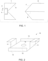
- Figure 1 shows a housing 1 for an optical device 2 such as a sensor.
- the optical device is provided in a cavity 3 in the housing 1.
- a surface 4 of the optical device 2 in this example is arranged to be exposed to a fluid to be tested to be able to measure a property of the fluid, such as its pressure.
- the housing 1 has a tapered surface 5 to receive a ferrule 6 with a correspondingly tapered portion 7 to be fitted therein and to present an end of a fibre 8 arranged to be mounted in the ferrule 6.
- housing tapered surface 5 and corresponding portion 7 of the ferrule 6 are shown as being conical or frusto-conical shaped, they could include any suitable tapered surface to enable the ferrule 6 to be precisely received within the housing to provide precise and reliable alignment of a fibre 8 with an optical device 2.
- the tapered surface 5 of the housing 1 is shown as being concave in Figure 1 with the corresponding tapered surface 7 of the ferrule 6 being convex.
- the tapered surface 5 of the housing 1 could be convex and the corresponding surface 7 of the ferrule 6 could be concave.
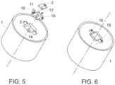
- FIG. 2 shows an example of a mounting bracket 10 that may be used to mount an optical device 2 to the housing 1 to accommodate thermal expansion of the housing 1 whilst still maintaining alignment of the optical device 2 with the fibre ⁇ .
- the mounting bracket 10 has two flexible supports 11 to be joined to the housing 1.
- the flexible supports 11 act as hinges when the housing 1 expands and contracts when exposed to various operating temperatures, eg 0°C and below to 400°C and above, to prevent radial thermal strain in the housing 1 from being transferred to a mounting surface 12 on which the optical device 2 is arranged to be provided.
- This example of the mounting bracket 10 also includes two stiffening beams 13 arranged along the sides between the flexible supports 11. The stiffening beams 13 prevent or reduce any bending of the base 12 as a result induced bending moments which could also be caused by thermal expansion and contraction of the housing 1 to which the mounting bracket 10 is, in use, attached.
- the example of the mounting bracket 10 in Figure 2 includes a window or hole 14 through which electromagnetic signals may be passed between the optical device 2 and the fibre 8.
- the window 14 could be any appropriate size and could occupy most of the base 12 of the mounting bracket 10 resulting in a supporting ledge around the inner edge of the base 12.
- the housing 1 may be secured to the ferrule 6 by any convenient means, such as by threads in or at the ends of the tapered surfaces 5, 7 or in appropriate flanges attached to one or both of the housing 1 and ferrule 6 fox example.
- the housing 1 is secured to the ferrule 6 sufficiently securely to generate a compressive pressure seal at the mating tapered surfaces 5, 7.
- the seal has been found to be suitable for use at high pressures and temperatures, such as 1000 bar and 400°C.
- FIGS 3 and 4 show a more detailed example of the present invention.
- the housing 1 is in the form of a pressure bulkhead with an internal cavity 3, containing a resonant silicon sensing element 2 supported via the strain-relieving mounting bracket 10.
- the internal cavity 3 in this example is bounded by a fusion welded isolation diaphragm 20 and fluid filled, for example with oil 21 under vacuum via a central fibre aperture 22.
- the fluid in the cavity 3 is transparent to the appropriate wavelength electromagnetic radiation provided to/from the optical device 2 that is used.
- a ferrule assembly consisting of an optical fibre 8 with a gold buffer 23 soldered or brazed into the metal ferrule 6, with a frusto-conical integral scaling face 7, is located into the tapered surface 5 of the housing 1 providing axial, angular and separation alignment to the sensing element target 2.
- a retaining screw 24 and backing spacer 25 are used to hold the ferrule 6 in place via a matching thread in the bulkhead 1, generating a compressive metal to metal pressure seal at the bulkhead mating coned surface 5 and sealing the fluid cavity.
- the bulkhead 1, diaphragm 20 and locking screw 24 may be made from a metal suitable for the operating environment conditions and process media in which the housing is to be used (typically a stainless steel, nickel alloy or titanium/titanium alloy for pressure sensing applications).
- a metal suitable for the operating environment conditions and process media in which the housing is to be used typically a stainless steel, nickel alloy or titanium/titanium alloy for pressure sensing applications.
- FIG. 5 shows the arrangement of an optical device 2 and mounting bracket 10 in a cavity 3 of a housing 1.
- the mounting bracket 10 may be made from a low thermal expansion metal (e.g. Nickel/Iron alloy) to provide a close thermal match to the optical device 2, which may be a silicon sensing element. It provides a stiff and stable base on which to attach the optical device 2, preferably with a suitable frit or die attachment adhesive that is not sensitive to the thermal expansion of the surrounding structure of the bulkhead 1. This stability of the mounting bracket 10 may be achieved by the use of the flexible mounting legs 11 that may be resistance welded or bonded 15 to the bulkhead 1. Alternatively or additionally stiffening beams 13 are provided along the sides of the base 12.
- a low thermal expansion metal e.g. Nickel/Iron alloy
- FIG. 6 shows the optical device 2 and mounting bracket 10 provided in the housing 1 with the mounting legs 11 attached 15 to the housing 1.
- a close thermal expansion match is preferable between the fibre 8 and ferrule 6 where they are joined, for example at a brazed joint, therefore a low thermal expansion ferrule 6 is used (e.g. Nickel/Iron alloy) with a high thermal expansion backing spacer 25 (e.g. Aluminium/Bronze Alloy or 300 series Stainless) as shown in Figure 7 .
- the spacer 25 serves the purpose of a thermal expansion compensator that counteracts any discrepancy in thermal expansion between the bulkhead 1 and ferrule 6 and maintains the axial compressive force at the coned surfaces 5, 7.
- retaining screw 24 is arranged to be secured to the housing 1, in this example via corresponding threads in each of the screw 24 and housing 1, to generate a compressive pressure seal at the mating tapered surface 7 of ferrule 6 and the corresponding tapered surface 5 of the housing 1 sealing the fluid cavity 3.
- the integrity of the pressure bulkhead 1 and the fluid cavity seal is provided over the operating temperature range to maintain both pressure containment and isolation of the sensing element 2.
- access to the cavity 3 is required for the optical fibre 8 and the fluid fill process. Any openings or feedthroughs therefore represent a potential containment integrity failure path.
- the mounting of the optical fibre 8 has been combined with the cavity seal mechanism as explained above.
- the housing 1 and optical device 2 need to be placed in both a weld chamber and an oil back-fill vacuum chamber to assemble the oil filled cavity 3.
- These chambers have limited space and it would therefore prove impractical to have a length of optical fibre already attached to the optical device 2.
- the ferrule 6 is arranged to be provided with the fibre 8 and to seal with the housing 1 via the tapered surfaces 5, 7 after the housing 1 with cavity 3 has been assembled, this problem is overcome.
- the combination of the fluid fill port and subsequent optical fibre attachment allows for a robust assembly process, where all welding operations and the vacuum fill process, are performed without the presence of a length of delicate and expensive optical fibre.
- the critical high risk processes in this assembly are performed up front allowing the functionality of the sensor to be verified and failed units scrapped prior to completion with the attachment of the ferrule to provide a seal.
- the ferrule 6 may be attached to the housing 1 to compress the mating tapered surfaces 5, 7 against each other in any desired way.
- the tapered surface 5 of the housing 1 is shown as being concave in Figure 1 with the corresponding tapered surface 7 of the ferrule 6 being convex.
- the tapered surface 5 of the housing 1 could be convex and the corresponding surface 7 of the ferrule 6 could be concave.
Landscapes
- Physics & Mathematics (AREA)
- General Physics & Mathematics (AREA)
- Optics & Photonics (AREA)
- Optical Couplings Of Light Guides (AREA)
Claims (13)
- Gehäuse (1), das eine verjüngte Oberfläche (5) aufweist, die mit einem entsprechend verjüngten Abschnitt (7) einer Faserhülse (6) in Eingriff zu bringen ist, in der eine Faser (8) angeordnet ist, um montiert zu werden, wobei, in Verwendung, die verjüngte Oberfläche (7) der Faserhülse (6) in Kontakt mit der entsprechenden verjüngten Oberfläche (5) des Gehäuses (1) gedrängt wird, um eine kompressive Druckdichtung an den zusammenpassenden verjüngten Oberflächen (5, 7) zu erzeugen;
dadurch gekennzeichnet, dass das Gehäuse (1) einen abgedichteten Hohlraum (3) aufweist, der eine optische Sensorvorrichtung (2) enthält und eine Oberfläche (20) aufweist, die angeordnet ist, um einem zu testenden Fluid ausgesetzt zu werden, um in der Lage zu sein, eine Eigenschaft des Fluids zu messen, wobei der abgedichtete Hohlraum (3) mit einem Fluid versehen ist, das für eine Wellenlänge von elektromagnetischer Strahlung transparent ist, die zu/von der optischen Vorrichtung (2) bereitgestellt ist, die in dem Hohlraum (3) bereitgestellt ist. - Gehäuse nach Anspruch 1, wobei das Gehäuse (1) eine kegelstumpfförmige Oberfläche aufweist, die mit einem entsprechend kegelstumpfförmigen Abschnitt einer Faserhülse (6) in Eingriff zu bringen ist.
- Gehäuse nach Anspruch 1 oder 2, wobei das Gehäuse (1) eine verjüngte Oberfläche aufweist, die mit einem entsprechend verjüngten Abschnitt einer Faserhülse (6) in Eingriff zu bringen ist.
- Gehäuse nach einem der vorstehenden Ansprüche, wobei die optische Vorrichtung ein resonantes Siliziumerfassungselement (2) ist und das Gehäuse (1) ferner eine Montagehalterung (10) umfasst, um das resonante Siliziumerfassungselement (2) zu tragen, wobei die Montagehalterung (10) flexible Träger (11) aufweist, die mit dem Gehäuse (1) verbunden sind, wobei die flexiblen Träger (11) das resonante Siliziumerfassungselement (2), das durch die Montagehalterung (10) zu tragen ist, von thermischer Dehnung in dem Gehäuse (1) isolieren.
- Gehäuse nach Anspruch 4, wobei die Montagehalterung (10) Versteifungsbalken (13) aufweist, die entlang der Seiten zwischen den flexiblen Trägern (11) angeordnet sind.
- Gehäuse nach einem der vorstehenden Ansprüche, wobei die Faserhülse (6) angeordnet ist, um an dem Gehäuse (1) ausreichend sicher gesichert zu sein, um eine kompressive Druckdichtung an den zusammenpassenden verjüngten Oberflächen (57) des Gehäuses (1) und der Faserhülse (6) zu erzeugen, um den Hohlraum (3) abzudichten.
- Gehäuse nach einem der vorstehenden Ansprüche, wobei die verjüngte Oberfläche (7) der Faserhülse (6) durch eine Kappe (24) um die Faserhülse (6) herum in Kontakt mit der entsprechenden verjüngten Oberfläche (5) des Gehäuses (1) gedrängt wird, wobei die Kappe (24) angeordnet ist, um auf das Gehäuse (1) geschraubt zu werden.
- Gehäuse nach Anspruch 7, wobei ein Abstandshalter (25) angeordnet ist, um zwischen der Faserhülse (6) und der Kappe (24) bereitgestellt zu werden, wobei der Abstandshalter (25) als ein thermischer Dehnungsausgleicher in Verwendung wirkt, um eine Kompressionsdichtung zwischen den in Eingriff gebrachten verjüngten Oberflächen (5, 7) aufrechtzuerhalten.
- Gehäuse nach einem der vorstehenden Ansprüche, wobei die verjüngte Oberfläche (5) an dem Gehäuse (1) konkav ist und der entsprechend verjüngte Abschnitt (7) der Faserhülse (6) konvex ist.
- Gehäuse (1) nach einem der vorstehenden Ansprüche, ferner umfassend eine Faserhülse (6) mit einem entsprechend verjüngten Abschnitt (7), der mit dem verjüngten Abschnitt (5) des Gehäuses (1) in Eingriff zu bringen ist.
- Verfahren zum Ausrichten einer Faser (8) mit einem Gehäuse (1) nach einem der vorstehenden Ansprüche, das Verfahren umfassend:
Drängen eines entsprechend verjüngten Abschnitts (7) einer Faserhülse (6), die eine darin montierte Faser (8) aufweist, in Kontakt mit dem verjüngten Abschnitt (5) des Gehäuses (1), um eine kompressive Druckdichtung an den zusammenpassenden verjüngten Oberflächen (5, 7) zu erzeugen. - Verfahren nach Anspruch 11, wobei die Faserhülse (6) an dem Gehäuse (1) gesichert ist, um eine kompressive Druckdichtung an den zusammenpassenden verjüngten Oberflächen (5, 7) des Gehäuses (1) und der Faserhülse (6) zu erzeugen, um den Hohlraum (3) in dem Gehäuse (1) für die optische Vorrichtung (2) abzudichten.
- Verfahren nach Anspruch 11 oder 12, wobei die optische Vorrichtung ein resonantes Siliziumerfassungselement (2) ist und das Gehäuse (1) ferner eine Montagehalterung (10) umfasst, um das resonante Siliziumerfassungselement (2) zu tragen, wobei die Montagehalterung (10) flexible Träger (11) aufweist, die mit dem Gehäuse (1) verbunden sind, wobei die flexiblen Träger (11) das resonante Siliziumerfassungselement (2), das durch die Montagehalterung (10) zu tragen ist, von thermischer Dehnung in dem Gehäuse (1) isolieren.
Applications Claiming Priority (2)
| Application Number | Priority Date | Filing Date | Title |
|---|---|---|---|
| GB1222628.8A GB2508907A (en) | 2012-12-14 | 2012-12-14 | Optical fibre alignment between ferrule and housing using tapered surfaces |
| PCT/US2013/069564 WO2014092906A1 (en) | 2012-12-14 | 2013-11-12 | Optical fibre alignment |
Publications (2)
| Publication Number | Publication Date |
|---|---|
| EP2932323A1 EP2932323A1 (de) | 2015-10-21 |
| EP2932323B1 true EP2932323B1 (de) | 2024-03-20 |
Family
ID=47630783
Family Applications (1)
| Application Number | Title | Priority Date | Filing Date |
|---|---|---|---|
| EP13793054.1A Active EP2932323B1 (de) | 2012-12-14 | 2013-11-12 | Glasfaserausrichtung |
Country Status (5)
| Country | Link |
|---|---|
| US (1) | US9588309B2 (de) |
| EP (1) | EP2932323B1 (de) |
| ES (1) | ES2981924T3 (de) |
| GB (1) | GB2508907A (de) |
| WO (1) | WO2014092906A1 (de) |
Families Citing this family (16)
| Publication number | Priority date | Publication date | Assignee | Title |
|---|---|---|---|---|
| US10511346B2 (en) | 2015-07-14 | 2019-12-17 | At&T Intellectual Property I, L.P. | Apparatus and methods for inducing electromagnetic waves on an uninsulated conductor |
| US10148016B2 (en) | 2015-07-14 | 2018-12-04 | At&T Intellectual Property I, L.P. | Apparatus and methods for communicating utilizing an antenna array |
| US10033107B2 (en) | 2015-07-14 | 2018-07-24 | At&T Intellectual Property I, L.P. | Method and apparatus for coupling an antenna to a device |
| US10790593B2 (en) | 2015-07-14 | 2020-09-29 | At&T Intellectual Property I, L.P. | Method and apparatus including an antenna comprising a lens and a body coupled to a feedline having a structure that reduces reflections of electromagnetic waves |
| US10341142B2 (en) | 2015-07-14 | 2019-07-02 | At&T Intellectual Property I, L.P. | Apparatus and methods for generating non-interfering electromagnetic waves on an uninsulated conductor |
| US10170840B2 (en) | 2015-07-14 | 2019-01-01 | At&T Intellectual Property I, L.P. | Apparatus and methods for sending or receiving electromagnetic signals |
| US9722318B2 (en) | 2015-07-14 | 2017-08-01 | At&T Intellectual Property I, L.P. | Method and apparatus for coupling an antenna to a device |
| US10129057B2 (en) | 2015-07-14 | 2018-11-13 | At&T Intellectual Property I, L.P. | Apparatus and methods for inducing electromagnetic waves on a cable |
| US10320586B2 (en) | 2015-07-14 | 2019-06-11 | At&T Intellectual Property I, L.P. | Apparatus and methods for generating non-interfering electromagnetic waves on an insulated transmission medium |
| US10205655B2 (en) | 2015-07-14 | 2019-02-12 | At&T Intellectual Property I, L.P. | Apparatus and methods for communicating utilizing an antenna array and multiple communication paths |
| US10033108B2 (en) | 2015-07-14 | 2018-07-24 | At&T Intellectual Property I, L.P. | Apparatus and methods for generating an electromagnetic wave having a wave mode that mitigates interference |
| US10065853B2 (en) * | 2016-05-23 | 2018-09-04 | Rosemount Aerospace Inc. | Optimized epoxy die attach geometry for MEMS die |
| US10488599B2 (en) * | 2017-06-07 | 2019-11-26 | Senko Advanced Components, Inc. | Optical interconnection system and mounting bracket for supporting a mated optical fiber ferrule assembly |
| WO2019104120A1 (en) * | 2017-11-22 | 2019-05-31 | At&T Intellectual Property I, L.P. | Method and apparatus for coupling to an antenna |
| US10564060B2 (en) * | 2018-02-09 | 2020-02-18 | General Electric Company | Pressure sensing devices, systems, and methods for alleviating interference from moisture |
| US12504587B2 (en) * | 2022-10-24 | 2025-12-23 | Baker Hughes Holdings Llc | Sealable fiber optic cable connection system |
Citations (3)
| Publication number | Priority date | Publication date | Assignee | Title |
|---|---|---|---|---|
| EP0092338B1 (de) * | 1982-04-16 | 1990-01-17 | Amp Incorporated | Faseroptisches Verbindungsstückgehäuse |
| US20060210231A1 (en) * | 2005-03-16 | 2006-09-21 | Christian Wittrisch | Sealed feedthrough assembly for optical fiber |
| US7499604B1 (en) * | 2004-12-12 | 2009-03-03 | Burns David W | Optically coupled resonant pressure sensor and process |
Family Cites Families (15)
| Publication number | Priority date | Publication date | Assignee | Title |
|---|---|---|---|---|
| US4479696A (en) | 1980-07-07 | 1984-10-30 | Hewlett-Packard Company | Housing for interfacing a semiconductor device with a fiber optic cable |
| JPS5860715A (ja) | 1981-10-06 | 1983-04-11 | Toyota Motor Corp | 光コネタク |
| US4699454A (en) | 1984-03-29 | 1987-10-13 | American Telephone And Telegraph Company, At&T Bell Laboratories | Fiber optic connector |
| US4699456A (en) | 1985-05-01 | 1987-10-13 | American Telephone And Telegraph Company, At&T Bell Laboratories | Hermetic fiber seal |
| US4875755A (en) | 1986-09-15 | 1989-10-24 | Tsi Incorporated | Fiber optic connector assembly and method of making same |
| FR2642851B1 (fr) | 1989-02-06 | 1991-10-31 | Quintel | Connecteur pour fibres optiques |
| US4883336A (en) | 1989-02-17 | 1989-11-28 | Conseil National De Recherches Du Canada | Method and leadthrough system for laying out optical fibres across an aperture of a container shell |
| US5065011A (en) * | 1989-07-20 | 1991-11-12 | Fujitsu Limited | Photodetector module for coupling with optical fiber |
| US5039193A (en) | 1990-04-03 | 1991-08-13 | Focal Technologies Incorporated | Fibre optic single mode rotary joint |
| SE9102851L (sv) | 1991-06-17 | 1992-12-18 | Stratos Connectors Ab | Anordning foer optisk anslutning av ett optiskt element till en lins |
| US6065882A (en) * | 1995-07-14 | 2000-05-23 | Cogent Light Technologies, Inc. | Snap-in proximal connector for mounting an optic fiber element into a light source system |
| US6295154B1 (en) * | 1998-06-05 | 2001-09-25 | Texas Instruments Incorporated | Optical switching apparatus |
| DE69928351D1 (de) * | 1998-10-20 | 2005-12-22 | Advanced Fiber Optics S L | Halter für optisches Faserbündel |
| US7489849B2 (en) * | 2004-11-03 | 2009-02-10 | Adc Telecommunications, Inc. | Fiber drop terminal |
| US8422835B2 (en) | 2005-06-30 | 2013-04-16 | Weatherford/Lamb, Inc. | Optical waveguide feedthrough assembly |
-
2012
- 2012-12-14 GB GB1222628.8A patent/GB2508907A/en not_active Withdrawn
-
2013
- 2013-11-12 ES ES13793054T patent/ES2981924T3/es active Active
- 2013-11-12 EP EP13793054.1A patent/EP2932323B1/de active Active
- 2013-11-12 WO PCT/US2013/069564 patent/WO2014092906A1/en not_active Ceased
- 2013-11-12 US US14/651,781 patent/US9588309B2/en active Active
Patent Citations (3)
| Publication number | Priority date | Publication date | Assignee | Title |
|---|---|---|---|---|
| EP0092338B1 (de) * | 1982-04-16 | 1990-01-17 | Amp Incorporated | Faseroptisches Verbindungsstückgehäuse |
| US7499604B1 (en) * | 2004-12-12 | 2009-03-03 | Burns David W | Optically coupled resonant pressure sensor and process |
| US20060210231A1 (en) * | 2005-03-16 | 2006-09-21 | Christian Wittrisch | Sealed feedthrough assembly for optical fiber |
Also Published As
| Publication number | Publication date |
|---|---|
| EP2932323A1 (de) | 2015-10-21 |
| US9588309B2 (en) | 2017-03-07 |
| US20150346440A1 (en) | 2015-12-03 |
| WO2014092906A1 (en) | 2014-06-19 |
| GB201222628D0 (en) | 2013-01-30 |
| ES2981924T3 (es) | 2024-10-11 |
| GB2508907A (en) | 2014-06-18 |
Similar Documents
| Publication | Publication Date | Title |
|---|---|---|
| US9588309B2 (en) | Optical fibre feedthrough assembly | |
| EP3128305B1 (de) | Hermetischer druckwandler | |
| EP2745087B1 (de) | Optischer sensor | |
| EP3353517B1 (de) | Optischer drucksensor mit reduzierten mechanischen spannungen | |
| EP3764072B1 (de) | Kompakt- oder miniatur-hochtemperatur-differenzdrucksensorkapsel | |
| EP2708866B1 (de) | Hermetisch glasversiegelter Drucksensor | |
| US20050195403A1 (en) | Optical fiber sensors for harsh environments | |
| US20020029639A1 (en) | Isolation technique for pressure sensing structure | |
| US20050195402A1 (en) | Crystalline optical fiber sensors for harsh environments | |
| KR20130019000A (ko) | 다이어프램 스트레스를 경감하기 위한 홈을 구비하는 정전 용량 압력 센서 | |
| CN101512314A (zh) | 压力测量变换器 | |
| US11754455B2 (en) | Pressure measuring device with free-standing carrier | |
| US9778130B2 (en) | Differential pressure transducer with inspectable welds | |
| WO2008060389A2 (en) | Sensor device package having thermally compliant die pad | |
| US11745288B2 (en) | Pressure measuring device having a membrane edge and mounting element connected by a diffusion weld | |
| US12590842B2 (en) | Photonic thermometer module assembly and performing photonic thermometry | |
| JP7102860B2 (ja) | 光モジュール | |
| JP2001091389A (ja) | 圧力測定用センサ | |
| WO2025085470A1 (en) | Non-metallic isolator systems for industrial process pressure transmitters | |
| US20110069318A1 (en) | Transducer for measuring environmental parameters | |
| CN120167035A (zh) | 用于工业过程压力变送器的非金属隔离器系统 | |
| JP2012522244A (ja) | 圧力センサ | |
| JP4882425B2 (ja) | 差圧測定装置 | |
| JP2014115098A (ja) | 差圧センサ | |
| JP2000131567A (ja) | 半導体レーザモジュール |
Legal Events
| Date | Code | Title | Description |
|---|---|---|---|
| PUAI | Public reference made under article 153(3) epc to a published international application that has entered the european phase |
Free format text: ORIGINAL CODE: 0009012 |
|
| 17P | Request for examination filed |
Effective date: 20150714 |
|
| AK | Designated contracting states |
Kind code of ref document: A1 Designated state(s): AL AT BE BG CH CY CZ DE DK EE ES FI FR GB GR HR HU IE IS IT LI LT LU LV MC MK MT NL NO PL PT RO RS SE SI SK SM TR |
|
| AX | Request for extension of the european patent |
Extension state: BA ME |
|
| DAX | Request for extension of the european patent (deleted) | ||
| STAA | Information on the status of an ep patent application or granted ep patent |
Free format text: STATUS: EXAMINATION IS IN PROGRESS |
|
| 17Q | First examination report despatched |
Effective date: 20190423 |
|
| RAP1 | Party data changed (applicant data changed or rights of an application transferred) |
Owner name: BAKER HUGHES HOLDINGS LLC |
|
| RAP3 | Party data changed (applicant data changed or rights of an application transferred) |
Owner name: BAKER HUGHES HOLDINGS LLC |
|
| P01 | Opt-out of the competence of the unified patent court (upc) registered |
Effective date: 20230526 |
|
| GRAP | Despatch of communication of intention to grant a patent |
Free format text: ORIGINAL CODE: EPIDOSNIGR1 |
|
| STAA | Information on the status of an ep patent application or granted ep patent |
Free format text: STATUS: GRANT OF PATENT IS INTENDED |
|
| GRAS | Grant fee paid |
Free format text: ORIGINAL CODE: EPIDOSNIGR3 |
|
| INTG | Intention to grant announced |
Effective date: 20240115 |
|
| GRAA | (expected) grant |
Free format text: ORIGINAL CODE: 0009210 |
|
| STAA | Information on the status of an ep patent application or granted ep patent |
Free format text: STATUS: THE PATENT HAS BEEN GRANTED |
|
| AK | Designated contracting states |
Kind code of ref document: B1 Designated state(s): AL AT BE BG CH CY CZ DE DK EE ES FI FR GB GR HR HU IE IS IT LI LT LU LV MC MK MT NL NO PL PT RO RS SE SI SK SM TR |
|
| REG | Reference to a national code |
Ref country code: GB Ref legal event code: FG4D |
|
| REG | Reference to a national code |
Ref country code: CH Ref legal event code: EP |
|
| REG | Reference to a national code |
Ref country code: IE Ref legal event code: FG4D |
|
| REG | Reference to a national code |
Ref country code: DE Ref legal event code: R096 Ref document number: 602013085465 Country of ref document: DE |
|
| PG25 | Lapsed in a contracting state [announced via postgrant information from national office to epo] |
Ref country code: LT Free format text: LAPSE BECAUSE OF FAILURE TO SUBMIT A TRANSLATION OF THE DESCRIPTION OR TO PAY THE FEE WITHIN THE PRESCRIBED TIME-LIMIT Effective date: 20240320 |
|
| REG | Reference to a national code |
Ref country code: LT Ref legal event code: MG9D |
|
| PG25 | Lapsed in a contracting state [announced via postgrant information from national office to epo] |
Ref country code: GR Free format text: LAPSE BECAUSE OF FAILURE TO SUBMIT A TRANSLATION OF THE DESCRIPTION OR TO PAY THE FEE WITHIN THE PRESCRIBED TIME-LIMIT Effective date: 20240621 |
|
| PG25 | Lapsed in a contracting state [announced via postgrant information from national office to epo] |
Ref country code: HR Free format text: LAPSE BECAUSE OF FAILURE TO SUBMIT A TRANSLATION OF THE DESCRIPTION OR TO PAY THE FEE WITHIN THE PRESCRIBED TIME-LIMIT Effective date: 20240320 Ref country code: RS Free format text: LAPSE BECAUSE OF FAILURE TO SUBMIT A TRANSLATION OF THE DESCRIPTION OR TO PAY THE FEE WITHIN THE PRESCRIBED TIME-LIMIT Effective date: 20240620 |
|
| REG | Reference to a national code |
Ref country code: NL Ref legal event code: MP Effective date: 20240320 |
|
| PG25 | Lapsed in a contracting state [announced via postgrant information from national office to epo] |
Ref country code: RS Free format text: LAPSE BECAUSE OF FAILURE TO SUBMIT A TRANSLATION OF THE DESCRIPTION OR TO PAY THE FEE WITHIN THE PRESCRIBED TIME-LIMIT Effective date: 20240620 Ref country code: NO Free format text: LAPSE BECAUSE OF FAILURE TO SUBMIT A TRANSLATION OF THE DESCRIPTION OR TO PAY THE FEE WITHIN THE PRESCRIBED TIME-LIMIT Effective date: 20240620 Ref country code: LT Free format text: LAPSE BECAUSE OF FAILURE TO SUBMIT A TRANSLATION OF THE DESCRIPTION OR TO PAY THE FEE WITHIN THE PRESCRIBED TIME-LIMIT Effective date: 20240320 Ref country code: HR Free format text: LAPSE BECAUSE OF FAILURE TO SUBMIT A TRANSLATION OF THE DESCRIPTION OR TO PAY THE FEE WITHIN THE PRESCRIBED TIME-LIMIT Effective date: 20240320 Ref country code: GR Free format text: LAPSE BECAUSE OF FAILURE TO SUBMIT A TRANSLATION OF THE DESCRIPTION OR TO PAY THE FEE WITHIN THE PRESCRIBED TIME-LIMIT Effective date: 20240621 Ref country code: FI Free format text: LAPSE BECAUSE OF FAILURE TO SUBMIT A TRANSLATION OF THE DESCRIPTION OR TO PAY THE FEE WITHIN THE PRESCRIBED TIME-LIMIT Effective date: 20240320 Ref country code: BG Free format text: LAPSE BECAUSE OF FAILURE TO SUBMIT A TRANSLATION OF THE DESCRIPTION OR TO PAY THE FEE WITHIN THE PRESCRIBED TIME-LIMIT Effective date: 20240320 |
|
| REG | Reference to a national code |
Ref country code: AT Ref legal event code: MK05 Ref document number: 1668340 Country of ref document: AT Kind code of ref document: T Effective date: 20240320 |
|
| PG25 | Lapsed in a contracting state [announced via postgrant information from national office to epo] |
Ref country code: SE Free format text: LAPSE BECAUSE OF FAILURE TO SUBMIT A TRANSLATION OF THE DESCRIPTION OR TO PAY THE FEE WITHIN THE PRESCRIBED TIME-LIMIT Effective date: 20240320 Ref country code: LV Free format text: LAPSE BECAUSE OF FAILURE TO SUBMIT A TRANSLATION OF THE DESCRIPTION OR TO PAY THE FEE WITHIN THE PRESCRIBED TIME-LIMIT Effective date: 20240320 |
|
| PG25 | Lapsed in a contracting state [announced via postgrant information from national office to epo] |
Ref country code: NL Free format text: LAPSE BECAUSE OF FAILURE TO SUBMIT A TRANSLATION OF THE DESCRIPTION OR TO PAY THE FEE WITHIN THE PRESCRIBED TIME-LIMIT Effective date: 20240320 |
|
| PG25 | Lapsed in a contracting state [announced via postgrant information from national office to epo] |
Ref country code: NL Free format text: LAPSE BECAUSE OF FAILURE TO SUBMIT A TRANSLATION OF THE DESCRIPTION OR TO PAY THE FEE WITHIN THE PRESCRIBED TIME-LIMIT Effective date: 20240320 |
|
| PG25 | Lapsed in a contracting state [announced via postgrant information from national office to epo] |
Ref country code: IS Free format text: LAPSE BECAUSE OF FAILURE TO SUBMIT A TRANSLATION OF THE DESCRIPTION OR TO PAY THE FEE WITHIN THE PRESCRIBED TIME-LIMIT Effective date: 20240720 |
|
| REG | Reference to a national code |
Ref country code: ES Ref legal event code: FG2A Ref document number: 2981924 Country of ref document: ES Kind code of ref document: T3 Effective date: 20241011 |
|
| PG25 | Lapsed in a contracting state [announced via postgrant information from national office to epo] |
Ref country code: PT Free format text: LAPSE BECAUSE OF FAILURE TO SUBMIT A TRANSLATION OF THE DESCRIPTION OR TO PAY THE FEE WITHIN THE PRESCRIBED TIME-LIMIT Effective date: 20240722 Ref country code: SM Free format text: LAPSE BECAUSE OF FAILURE TO SUBMIT A TRANSLATION OF THE DESCRIPTION OR TO PAY THE FEE WITHIN THE PRESCRIBED TIME-LIMIT Effective date: 20240320 |
|
| PG25 | Lapsed in a contracting state [announced via postgrant information from national office to epo] |
Ref country code: EE Free format text: LAPSE BECAUSE OF FAILURE TO SUBMIT A TRANSLATION OF THE DESCRIPTION OR TO PAY THE FEE WITHIN THE PRESCRIBED TIME-LIMIT Effective date: 20240320 Ref country code: CZ Free format text: LAPSE BECAUSE OF FAILURE TO SUBMIT A TRANSLATION OF THE DESCRIPTION OR TO PAY THE FEE WITHIN THE PRESCRIBED TIME-LIMIT Effective date: 20240320 |
|
| PG25 | Lapsed in a contracting state [announced via postgrant information from national office to epo] |
Ref country code: AT Free format text: LAPSE BECAUSE OF FAILURE TO SUBMIT A TRANSLATION OF THE DESCRIPTION OR TO PAY THE FEE WITHIN THE PRESCRIBED TIME-LIMIT Effective date: 20240320 |
|
| PG25 | Lapsed in a contracting state [announced via postgrant information from national office to epo] |
Ref country code: PL Free format text: LAPSE BECAUSE OF FAILURE TO SUBMIT A TRANSLATION OF THE DESCRIPTION OR TO PAY THE FEE WITHIN THE PRESCRIBED TIME-LIMIT Effective date: 20240320 |
|
| PG25 | Lapsed in a contracting state [announced via postgrant information from national office to epo] |
Ref country code: SK Free format text: LAPSE BECAUSE OF FAILURE TO SUBMIT A TRANSLATION OF THE DESCRIPTION OR TO PAY THE FEE WITHIN THE PRESCRIBED TIME-LIMIT Effective date: 20240320 |
|
| PG25 | Lapsed in a contracting state [announced via postgrant information from national office to epo] |
Ref country code: SM Free format text: LAPSE BECAUSE OF FAILURE TO SUBMIT A TRANSLATION OF THE DESCRIPTION OR TO PAY THE FEE WITHIN THE PRESCRIBED TIME-LIMIT Effective date: 20240320 Ref country code: SK Free format text: LAPSE BECAUSE OF FAILURE TO SUBMIT A TRANSLATION OF THE DESCRIPTION OR TO PAY THE FEE WITHIN THE PRESCRIBED TIME-LIMIT Effective date: 20240320 Ref country code: RO Free format text: LAPSE BECAUSE OF FAILURE TO SUBMIT A TRANSLATION OF THE DESCRIPTION OR TO PAY THE FEE WITHIN THE PRESCRIBED TIME-LIMIT Effective date: 20240320 Ref country code: PT Free format text: LAPSE BECAUSE OF FAILURE TO SUBMIT A TRANSLATION OF THE DESCRIPTION OR TO PAY THE FEE WITHIN THE PRESCRIBED TIME-LIMIT Effective date: 20240722 Ref country code: PL Free format text: LAPSE BECAUSE OF FAILURE TO SUBMIT A TRANSLATION OF THE DESCRIPTION OR TO PAY THE FEE WITHIN THE PRESCRIBED TIME-LIMIT Effective date: 20240320 Ref country code: IS Free format text: LAPSE BECAUSE OF FAILURE TO SUBMIT A TRANSLATION OF THE DESCRIPTION OR TO PAY THE FEE WITHIN THE PRESCRIBED TIME-LIMIT Effective date: 20240720 Ref country code: EE Free format text: LAPSE BECAUSE OF FAILURE TO SUBMIT A TRANSLATION OF THE DESCRIPTION OR TO PAY THE FEE WITHIN THE PRESCRIBED TIME-LIMIT Effective date: 20240320 Ref country code: CZ Free format text: LAPSE BECAUSE OF FAILURE TO SUBMIT A TRANSLATION OF THE DESCRIPTION OR TO PAY THE FEE WITHIN THE PRESCRIBED TIME-LIMIT Effective date: 20240320 Ref country code: AT Free format text: LAPSE BECAUSE OF FAILURE TO SUBMIT A TRANSLATION OF THE DESCRIPTION OR TO PAY THE FEE WITHIN THE PRESCRIBED TIME-LIMIT Effective date: 20240320 |
|
| REG | Reference to a national code |
Ref country code: DE Ref legal event code: R097 Ref document number: 602013085465 Country of ref document: DE |
|
| PG25 | Lapsed in a contracting state [announced via postgrant information from national office to epo] |
Ref country code: DK Free format text: LAPSE BECAUSE OF FAILURE TO SUBMIT A TRANSLATION OF THE DESCRIPTION OR TO PAY THE FEE WITHIN THE PRESCRIBED TIME-LIMIT Effective date: 20240320 |
|
| PLBE | No opposition filed within time limit |
Free format text: ORIGINAL CODE: 0009261 |
|
| STAA | Information on the status of an ep patent application or granted ep patent |
Free format text: STATUS: NO OPPOSITION FILED WITHIN TIME LIMIT |
|
| PG25 | Lapsed in a contracting state [announced via postgrant information from national office to epo] |
Ref country code: DK Free format text: LAPSE BECAUSE OF FAILURE TO SUBMIT A TRANSLATION OF THE DESCRIPTION OR TO PAY THE FEE WITHIN THE PRESCRIBED TIME-LIMIT Effective date: 20240320 |
|
| 26N | No opposition filed |
Effective date: 20241223 |
|
| PG25 | Lapsed in a contracting state [announced via postgrant information from national office to epo] |
Ref country code: SI Free format text: LAPSE BECAUSE OF FAILURE TO SUBMIT A TRANSLATION OF THE DESCRIPTION OR TO PAY THE FEE WITHIN THE PRESCRIBED TIME-LIMIT Effective date: 20240320 |
|
| REG | Reference to a national code |
Ref country code: CH Ref legal event code: PL |
|
| PG25 | Lapsed in a contracting state [announced via postgrant information from national office to epo] |
Ref country code: MC Free format text: LAPSE BECAUSE OF FAILURE TO SUBMIT A TRANSLATION OF THE DESCRIPTION OR TO PAY THE FEE WITHIN THE PRESCRIBED TIME-LIMIT Effective date: 20240320 |
|
| PG25 | Lapsed in a contracting state [announced via postgrant information from national office to epo] |
Ref country code: LU Free format text: LAPSE BECAUSE OF NON-PAYMENT OF DUE FEES Effective date: 20241112 |
|
| REG | Reference to a national code |
Ref country code: CH Ref legal event code: PL |
|
| PG25 | Lapsed in a contracting state [announced via postgrant information from national office to epo] |
Ref country code: CH Free format text: LAPSE BECAUSE OF NON-PAYMENT OF DUE FEES Effective date: 20241130 |
|
| REG | Reference to a national code |
Ref country code: BE Ref legal event code: MM Effective date: 20241130 |
|
| PG25 | Lapsed in a contracting state [announced via postgrant information from national office to epo] |
Ref country code: BE Free format text: LAPSE BECAUSE OF NON-PAYMENT OF DUE FEES Effective date: 20241130 |
|
| PG25 | Lapsed in a contracting state [announced via postgrant information from national office to epo] |
Ref country code: IE Free format text: LAPSE BECAUSE OF NON-PAYMENT OF DUE FEES Effective date: 20241112 |
|
| PGFP | Annual fee paid to national office [announced via postgrant information from national office to epo] |
Ref country code: DE Payment date: 20251022 Year of fee payment: 13 |
|
| PGFP | Annual fee paid to national office [announced via postgrant information from national office to epo] |
Ref country code: GB Payment date: 20251022 Year of fee payment: 13 |
|
| PGFP | Annual fee paid to national office [announced via postgrant information from national office to epo] |
Ref country code: IT Payment date: 20251022 Year of fee payment: 13 |
|
| PGFP | Annual fee paid to national office [announced via postgrant information from national office to epo] |
Ref country code: FR Payment date: 20251023 Year of fee payment: 13 |
|
| PGFP | Annual fee paid to national office [announced via postgrant information from national office to epo] |
Ref country code: ES Payment date: 20251201 Year of fee payment: 13 |
|
| PG25 | Lapsed in a contracting state [announced via postgrant information from national office to epo] |
Ref country code: HU Free format text: LAPSE BECAUSE OF FAILURE TO SUBMIT A TRANSLATION OF THE DESCRIPTION OR TO PAY THE FEE WITHIN THE PRESCRIBED TIME-LIMIT; INVALID AB INITIO Effective date: 20131112 |
|
| PG25 | Lapsed in a contracting state [announced via postgrant information from national office to epo] |
Ref country code: CY Free format text: LAPSE BECAUSE OF FAILURE TO SUBMIT A TRANSLATION OF THE DESCRIPTION OR TO PAY THE FEE WITHIN THE PRESCRIBED TIME-LIMIT; INVALID AB INITIO Effective date: 20131112 |