EP2932281B1 - Methods and circuits for measuring a high impedance element based on time constant measurements - Google Patents
Methods and circuits for measuring a high impedance element based on time constant measurements Download PDFInfo
- Publication number
- EP2932281B1 EP2932281B1 EP13811751.0A EP13811751A EP2932281B1 EP 2932281 B1 EP2932281 B1 EP 2932281B1 EP 13811751 A EP13811751 A EP 13811751A EP 2932281 B1 EP2932281 B1 EP 2932281B1
- Authority
- EP
- European Patent Office
- Prior art keywords
- capacitor
- impedance
- time constant
- test
- determining
- Prior art date
- Legal status (The legal status is an assumption and is not a legal conclusion. Google has not performed a legal analysis and makes no representation as to the accuracy of the status listed.)
- Active
Links
- 238000000034 method Methods 0.000 title claims description 15
- 238000005259 measurement Methods 0.000 title description 4
- 239000003990 capacitor Substances 0.000 claims description 61
- 238000012360 testing method Methods 0.000 claims description 46
- 239000000523 sample Substances 0.000 claims description 26
- 238000002847 impedance measurement Methods 0.000 claims description 15
- 239000013618 particulate matter Substances 0.000 claims description 13
- 238000007599 discharging Methods 0.000 claims description 4
- 238000010586 diagram Methods 0.000 description 11
- 238000004590 computer program Methods 0.000 description 6
- 238000012545 processing Methods 0.000 description 5
- 230000000694 effects Effects 0.000 description 4
- 230000006870 function Effects 0.000 description 4
- 238000002955 isolation Methods 0.000 description 3
- 230000033228 biological regulation Effects 0.000 description 2
- 239000000428 dust Substances 0.000 description 2
- 238000012986 modification Methods 0.000 description 2
- 230000004048 modification Effects 0.000 description 2
- 238000009825 accumulation Methods 0.000 description 1
- 230000002411 adverse Effects 0.000 description 1
- 238000004458 analytical method Methods 0.000 description 1
- 238000011109 contamination Methods 0.000 description 1
- 238000001514 detection method Methods 0.000 description 1
- 230000005684 electric field Effects 0.000 description 1
- 238000005516 engineering process Methods 0.000 description 1
- 238000004519 manufacturing process Methods 0.000 description 1
- 238000012544 monitoring process Methods 0.000 description 1
- 238000000275 quality assurance Methods 0.000 description 1
Images


Classifications
-
- G—PHYSICS
- G01—MEASURING; TESTING
- G01R—MEASURING ELECTRIC VARIABLES; MEASURING MAGNETIC VARIABLES
- G01R27/00—Arrangements for measuring resistance, reactance, impedance, or electric characteristics derived therefrom
- G01R27/02—Measuring real or complex resistance, reactance, impedance, or other two-pole characteristics derived therefrom, e.g. time constant
- G01R27/26—Measuring inductance or capacitance; Measuring quality factor, e.g. by using the resonance method; Measuring loss factor; Measuring dielectric constants ; Measuring impedance or related variables
-
- G—PHYSICS
- G01—MEASURING; TESTING
- G01R—MEASURING ELECTRIC VARIABLES; MEASURING MAGNETIC VARIABLES
- G01R27/00—Arrangements for measuring resistance, reactance, impedance, or electric characteristics derived therefrom
- G01R27/02—Measuring real or complex resistance, reactance, impedance, or other two-pole characteristics derived therefrom, e.g. time constant
- G01R27/025—Measuring very high resistances, e.g. isolation resistances, i.e. megohm-meters
-
- G—PHYSICS
- G01—MEASURING; TESTING
- G01N—INVESTIGATING OR ANALYSING MATERIALS BY DETERMINING THEIR CHEMICAL OR PHYSICAL PROPERTIES
- G01N27/00—Investigating or analysing materials by the use of electric, electrochemical, or magnetic means
- G01N27/02—Investigating or analysing materials by the use of electric, electrochemical, or magnetic means by investigating impedance
- G01N27/22—Investigating or analysing materials by the use of electric, electrochemical, or magnetic means by investigating impedance by investigating capacitance
- G01N27/228—Circuits therefor
-
- G—PHYSICS
- G01—MEASURING; TESTING
- G01N—INVESTIGATING OR ANALYSING MATERIALS BY DETERMINING THEIR CHEMICAL OR PHYSICAL PROPERTIES
- G01N27/00—Investigating or analysing materials by the use of electric, electrochemical, or magnetic means
- G01N27/60—Investigating or analysing materials by the use of electric, electrochemical, or magnetic means by investigating electrostatic variables, e.g. electrographic flaw testing
Definitions
- the present invention relates to electrical circuit element measurement technology, and, more particularly, to methods and circuits for measuring high impedance elements.
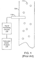
- FIG. 1 illustrates an example where electrical isolation of measurement circuit components is important to obtain valid data.
- FIG. 1 is a diagram that illustrates circuitry for evaluating the concentration of particulate in a gas stream.
- a stack 105 has a gas that flows therethrough and contains particulate matter 110.
- a probe 115 is configured to extend into the gas stream and is charged through a triboelectric effect by the particulate matter 110 colliding with the probe 115. The triboelectric effect results in an signal being generated, which can be processed by signal processing circuitry 120 and provided as an input to a particulate matter analysis module 125 to evaluate the concentration of the particulate 110 matter in the gas stream.
- the particulate matter 110 in the gas stream along with dust and other foreign debris can build up on surfaces of the stack 105 and/or the probe 115 and have the potential to affect the electrical characteristics of the probe 115. For example, build-up of debris adjacent to the probe 115 may create electrical paths to ground or other electrical circuits resulting in a signal output from probe 115 that is not representative of the concentration of the particulate matter 110 in the gas stream.
- US 5 287 061 A describes a method of detecting contamination of a triboelectric probe disposed in a gas stream containing particulate matter. To this end an AC test signal is applied to an input of a signal amplifier to which also the triboelectric probe is connected.
- determining the first time constant comprises driving a test circuit comprising the known impedance and the capacitor connected in series with a first test voltage.
- the first test voltage is in a range from about 0V to about 3.3V.
- the known impedance has a that value is in a range from about 1 megaohm to about 10 megaohms.
- the capacitor has a value in a range from about 1 nanofarad to about 10 nanofarads.
- determining the first time constant further comprises charging the capacitor with the first test voltage and determining a time taken to charge the capacitor to a threshold voltage level.
- determining the first time constant further comprises charging the capacitor to a known voltage level, discharging the capacitor through the known impedance, and determining a time taken for the capacitor voltage level to decrease to a threshold voltage level.
- determining the second time constant comprises, replacing the known impedance in the test circuit with the target impedance and driving the test circuit comprising the target impedance and the capacitor connected in series with a second test voltage.
- the first and second test voltages are the same.
- the first and second test voltages are different.
- the second test voltage is in a range from about 0V to about 24V.
- the target impedance has a value is in a range from about 10 megaohms to about 50 megaohms.
- determining the second time constant further comprises charging the capacitor with the second test voltage and determining a time taken to charge the capacitor to a threshold voltage level.
- determining the second time constant further comprises charging the capacitor to a known voltage level, discharging the capacitor through the target impedance, and determining a time taken for the capacitor voltage level to decrease to a threshold voltage level.
- the target impedance comprises an electrical path between a triboelectric probe and a common node.
- the triboelectric probe is adapted to be disposed in a gas stream containing particulate matter.
- an impedance measurement circuit comprises a test circuit comprising a capacitor connected to a test voltage and a controller that is configured to switch a known impedance in series with the capacitance and the test voltage to determine a first time constant based on the known impedance and the capacitor, to a target impedance in series with the capacitance in place of the known impedance to determine a second time constant based on the target impedance and the capacitor, and to determine the target impedance based on the first time constant and the second time constant.
- the controller is further configured to determine the first time constant by charging the capacitor with the test voltage.
- the impedance measurement circuit further comprises a voltage comparator that is configured to determine when the capacitor is charged to a threshold voltage level and a timer that is configured to determine a time taken to charge the capacitor to the threshold voltage level.
- the controller is further configured to determine the second time constant by charging the capacitor with the test voltage.
- the impedance measurement circuit further comprises a voltage comparator that is configured to determine when the capacitor is charged to a threshold voltage level and a timer that is configured to determine a time taken to charge the capacitor to the threshold voltage level.
- a computer program product for measuring an impedance comprises a non-transitory computer readable medium comprising computer readable program code thereon.
- the computer readable program code comprises computer readable program code configured to determine a first time constant based on a known impedance and a capacitor, computer readable program code configured to determine a second time constant based on a target impedance and the capacitor, and computer readable program code configured to determine the target impedance based on the first time constant and the second time constant.
- the embodiments of the present invention are described herein in the context of measuring the impedance of a triboelectric probe relative to a reference node voltage (e.g., ground) to ensure that the probe is sufficiently electrically isolated to generate a signal indicative of particulate matter concentration in a gas stream.
- a reference node voltage e.g., ground
- a target impedance can be measured based on time constant determinations of a capacitive circuit with both a known impedance and the target impedance. Because the time constant measurements are independent of the voltage used to drive the capacitive circuit, high voltages can be avoided providing a safer methodology for measuring the target impedance.
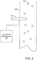
- FIG. 2 illustrates an application for measuring a target impedance using an impedance measurement circuit according to some embodiments of the present invention.
- FIG. 2 is similar to FIG. 1 and illustrates circuitry for evaluating the concentration of particulate in a gas stream.
- a stack 205 has a gas that flows therethrough and contains particulate matter 210.
- a probe 215 is configured to extend into the gas stream and is charged through a triboelectric effect by the particulate matter 210 colliding with the probe 215. The triboelectric effect results in a signal being generated, which can be processed to evaluate the concentration of the particulate 210 matter in the gas stream as described above.
- build-up of debris adjacent to the probe 215 may create electrical paths to ground or other electrical circuits resulting in a signal output from probe 215 that is not representative of the concentration of the particulate matter 210 in the gas stream.
- the impedance measurement circuit 220 may be connected to the probe 215 to measure a target impedance between the probe 215 and ground or another reference node based on time constant determinations.
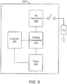
- FIG. 3 is a block diagram of the impedance measurement circuit 220 of FIG. 2 according to some embodiments of the present invention.
- the impedance measurement circuit 220 comprises an RC test circuit 305, a voltage comparator 310, a timer 315, and a controller 320, which are connected as shown.
- a target impedance to be measured which is identified as Z load , can be switched into the RC test circuit 305 for determining a time constant based on the target impedance.
- the voltage comparator 310 and the timer 315 are configured to determine a time for a voltage to reach a specific threshold level in the RC test circuit 305 to obtain a time constant value.
- the controller 320 is configured to coordinate the operations of the other components of the impedance measurement circuit 220 including switches and to process the data from the timer and 315 and known circuit element values from the RC test circuit 305 to determine the value of the target impedance Z load .
- FIG. 4 is a schematic of the RC test circuit 305 of FIG. 3 according to some embodiments of the present invention.
- the RC test circuit schematic 400 includes a capacitor C1 that can be coupled to one of two impedance elements Z1 or Z2 via switches 405 and 415.
- impedance element Z1 may be a known impedance value while impedance value Z2 may be a target impedance whose value is unknown.
- the switch 405 may be closed and the switch 415 may be used to select the known impedance element Z1 to charge the capacitor C1 with the voltage Vtest. This operation may be performed to confirm the time constant based on the known circuit elements of C1 and Z1. As shown in FIG.
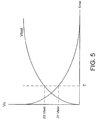
- the capacitor C1 charges at a rate such that the voltage across capacitor C1 is 63% of the charging voltage Vtest at a time T corresponding to one time constant.
- the controller 320 may activate the timer circuit 315 when switches 405 and 415 are activated and the voltage comparator 310 of FIG. 1 may determine when the voltage across the capacitor C1 reaches 63% of the drive voltage Vtest.
- the timer circuit 315 may then be deactivated and the time recorded, which is equal to one time constant T. This value may be used to confirm the accuracy of the values of the known components C1 and Z1, i.e., the time constant T may be compared to the product of C1 and Z1.
- the controller 320 may then discharge the capacitor C1 by opening the switch 405 and closing the switch 410. Similar operations may then be performed for the target impedance Z2 whose impedance value is unknown by closing the switch 405 and selecting impedance element Z2 with switch 415.
- time constant determinations for the RC circuits comprising C1-Z1 and C2-Z2 may also be performed by charging the capacitor C1 to the Vtest drive voltage value and then opening switch 405 and closing switch 410 at which time the timer circuit 315 is activated.
- the voltage comparator 315 may then determine when the voltage across the capacitor reaches 37% of the drive voltage Vtest as shown in FIG. 5 .
- the timer circuit 315 is then deactivated and the time recorded, which is equal to one time constant.
- the voltage threshold used for deactivating the timer circuit 315 may selected for convenience and ease of detection with the time constant being determined according to the time along the exponential curves of FIG. 5 that the voltage threshold is reached.
- the time constant is independent of the value of driving voltage Vtest
- a voltage may be selected for Vtest that provides a desired level of safety and is suitable for the voltage comparator 310.
- Vtest may be set to different values when determining the time constants for the known impedance Z1 and the target impedance Z2 or Vtest may be set to the same voltage level for both time constant determinations.
- the capacitor C1 may have a value in a range from about 1 nanofarads to about 10 nanofarads.
- the known impedance Z1 may have a resistance value in a range from about 1 megaohm to about 10 megaohms.
- the voltage Vtest used to determine the time constant for C 1 and Z1 may have a voltage value in a range from about 0V to about 3.3V.
- the voltage Vtest used to determine the time constant for C1 and the target impedance Z2 may have a voltage value in a range from about 0V to about 24V.
- These computer program instructions may be provided to a processor of a general purpose computer, a special purpose computer, or other programmable data processing apparatus to produce a machine, such that the instructions, which execute via the processor of the computer or other programmable data processing apparatus, create means and/or circuits for implementing the functions specified in the flowchart and/or block diagram block or blocks.
- These computer program instructions may also be stored in a computer usable or computer-readable memory that may direct a computer or other programmable data processing apparatus to function in a particular manner, such that the instructions stored in the computer usable or computer-readable memory produce an article of manufacture including instructions that implement the function specified in the flowchart, information flow, and/or block diagram block or blocks.
- the computer program instructions may also be loaded onto a computer or other programmable data processing apparatus to cause a series of operational steps to be performed on the computer or other programmable apparatus to produce a computer implemented process such that the instructions that execute on the computer or other programmable apparatus provide steps for implementing the functions specified in the flowchart, information flow, and/or block diagram block or blocks.
- FIG. 6 is a flow chart that illustrates operations for measuring a target impedance according to some embodiments of the present invention.
- Operations begin at block 605 where a first time constant is determined based on a known impedance and capacitance, such as capacitor C1 and impedance Z1 described above with respect to FIG. 5 .
- a second time constant based on a target impedance, whose value is unknown, and the known capacitor, such as capacitor C1 and impedance Z2 described above with respect to FIG. 5 is determined at block 610.
- the target impedance may be determined at block 615 based on the first time constant and the second time constant.
- embodiments of the present invention may allow a technician to determine an unknown impedance value, which may be very high, without the need to use a high voltage, which may be dangerous or even disallowed due to safety regulations.
- the impedance test circuit may be applied to simple hand-held devices that could allow technicians to conduct field testing of components.
- the test circuitry may be added to various types of instruments where a resistance check between a probe and ground or other reference point could provide additional quality assurance checks to the data reliability.
- the impedance test circuit may also be incorporated into electronic devices, computers, embedded systems, and the like for monitoring dust build-up and debris accumulation, particularly in environmentally unfriendly conditions.
Landscapes
- Physics & Mathematics (AREA)
- General Physics & Mathematics (AREA)
- Chemical & Material Sciences (AREA)
- Chemical Kinetics & Catalysis (AREA)
- Electrochemistry (AREA)
- Health & Medical Sciences (AREA)
- Life Sciences & Earth Sciences (AREA)
- Analytical Chemistry (AREA)
- Biochemistry (AREA)
- General Health & Medical Sciences (AREA)
- Immunology (AREA)
- Pathology (AREA)
- Measurement Of Resistance Or Impedance (AREA)
- Measurement Of Unknown Time Intervals (AREA)
Priority Applications (1)
| Application Number | Priority Date | Filing Date | Title |
|---|---|---|---|
| PL13811751T PL2932281T3 (pl) | 2012-12-11 | 2013-12-11 | Sposoby i obwody do pomiaru elementu o wysokiej impedancji w oparciu o pomiary stałej czasowej |
Applications Claiming Priority (2)
| Application Number | Priority Date | Filing Date | Title |
|---|---|---|---|
| US13/710,896 US9482706B2 (en) | 2012-12-11 | 2012-12-11 | Methods and circuits for measuring a high impedance element based on time constant measurements |
| PCT/US2013/074266 WO2014093426A1 (en) | 2012-12-11 | 2013-12-11 | Methods and circuits for measuring a high impedance element based on time constant measurements |
Publications (2)
| Publication Number | Publication Date |
|---|---|
| EP2932281A1 EP2932281A1 (en) | 2015-10-21 |
| EP2932281B1 true EP2932281B1 (en) | 2021-09-29 |
Family
ID=49877066
Family Applications (1)
| Application Number | Title | Priority Date | Filing Date |
|---|---|---|---|
| EP13811751.0A Active EP2932281B1 (en) | 2012-12-11 | 2013-12-11 | Methods and circuits for measuring a high impedance element based on time constant measurements |
Country Status (6)
| Country | Link |
|---|---|
| US (1) | US9482706B2 (es) |
| EP (1) | EP2932281B1 (es) |
| CA (1) | CA2894759C (es) |
| MX (1) | MX347311B (es) |
| PL (1) | PL2932281T3 (es) |
| WO (1) | WO2014093426A1 (es) |
Families Citing this family (3)
| Publication number | Priority date | Publication date | Assignee | Title |
|---|---|---|---|---|
| DE102014207478A1 (de) * | 2014-04-17 | 2015-10-22 | Robert Bosch Gmbh | Verfahren und Vorrichtung zur Ermittlung eines Isolationswiderstandes sowie Hochvoltbatteriesystem mit einer solchen Vorrichtung |
| US20170219545A1 (en) * | 2016-02-02 | 2017-08-03 | Empire Technology Development Llc | Produce item ripeness determination |
| EP3553538B1 (en) * | 2018-04-13 | 2021-03-10 | Nokia Technologies Oy | An apparatus, electronic device and method for estimating impedance |
Family Cites Families (16)
| Publication number | Priority date | Publication date | Assignee | Title |
|---|---|---|---|---|
| DE3642861A1 (de) | 1986-12-16 | 1988-06-30 | Diehl Gmbh & Co | Schaltungsanordnung |
| US5287061A (en) * | 1992-05-19 | 1994-02-15 | Auburn International, Inc. | On line triboelectric probe contamination detector |
| US5371469A (en) * | 1993-02-16 | 1994-12-06 | The United States Of America As Represented By The Administrator Of The National Aeronautics And Space Administration | Constant current loop impedance measuring system that is immune to the effects of parasitic impedances |
| JPH07218596A (ja) * | 1994-02-03 | 1995-08-18 | Mitsubishi Electric Corp | 半導体試験装置 |
| DE69511020T2 (de) * | 1994-04-05 | 2000-02-24 | Koninkl Philips Electronics Nv | Widerstandsmessschaltung, und thermische vorrichtung, elektrischer temperaturfühler und kälteerzeugungsvorrichtung mit einer solchen messschaltung |
| DE4420998C2 (de) | 1994-06-17 | 1999-03-25 | Diehl Stiftung & Co | Schaltungseinrichtung zum genauen Messen eines elektrischen Widerstandes |
| JP3224977B2 (ja) * | 1994-12-12 | 2001-11-05 | 本田技研工業株式会社 | 非接地電源の絶縁検出方法及び装置 |
| DE19546304A1 (de) | 1995-12-12 | 1997-06-19 | Ingenieurgesellschaft Tempelwa | Schaltungsanordnung zur Temperaturmessung |
| US6191723B1 (en) | 1999-07-22 | 2001-02-20 | Fluke Corporation | Fast capacitance measurement |
| AUPQ685900A0 (en) | 2000-04-12 | 2000-05-11 | Goyen Controls Co Pty Limited | Method and apparatus for detecting particles in a gas flow |
| CA2407766C (en) * | 2000-11-22 | 2010-06-29 | Ecole De Technologie Superieure | Vddq integrated circuit testing system and method |
| DE10119080B4 (de) | 2001-04-19 | 2005-05-04 | Acam-Messelectronic Gmbh | Verfahren und Schaltanordnung zur Widerstandsmessung |
| US20030151418A1 (en) * | 2002-02-08 | 2003-08-14 | Leger Roger Joseph | Low voltage circuit tester |
| KR20050057517A (ko) * | 2002-09-20 | 2005-06-16 | 코닌클리즈케 필립스 일렉트로닉스 엔.브이. | 회로의 정지 전류를 테스팅하는 테스트 장치 및 디바이스테스트 방법과 집적 회로 |
| US7173438B2 (en) | 2005-05-18 | 2007-02-06 | Seagate Technology Llc | Measuring capacitance |
| FR2978828B1 (fr) * | 2011-08-02 | 2013-09-06 | Snecma | Capteur multi-electrode pour determiner la teneur en gaz dans un ecoulement diphasique |
-
2012
- 2012-12-11 US US13/710,896 patent/US9482706B2/en active Active
-
2013
- 2013-12-11 MX MX2015007420A patent/MX347311B/es active IP Right Grant
- 2013-12-11 CA CA2894759A patent/CA2894759C/en active Active
- 2013-12-11 WO PCT/US2013/074266 patent/WO2014093426A1/en active Application Filing
- 2013-12-11 EP EP13811751.0A patent/EP2932281B1/en active Active
- 2013-12-11 PL PL13811751T patent/PL2932281T3/pl unknown
Also Published As
| Publication number | Publication date |
|---|---|
| MX347311B (es) | 2017-04-20 |
| CA2894759A1 (en) | 2014-06-19 |
| PL2932281T3 (pl) | 2022-02-14 |
| US9482706B2 (en) | 2016-11-01 |
| MX2015007420A (es) | 2015-12-03 |
| US20140159747A1 (en) | 2014-06-12 |
| EP2932281A1 (en) | 2015-10-21 |
| CA2894759C (en) | 2021-04-20 |
| WO2014093426A1 (en) | 2014-06-19 |
Similar Documents
| Publication | Publication Date | Title |
|---|---|---|
| KR101144684B1 (ko) | 전지 특성 평가 장치 | |
| US9588180B2 (en) | Architecture and method to determine leakage impedance and leakage voltage node | |
| CN109425816B (zh) | 测试mos功率开关 | |
| EP3098600B1 (en) | Surface property inspection method | |
| JP6154068B2 (ja) | 飽和を検出及び/又は防止する磁気流量計 | |
| JP6061213B2 (ja) | 静電気放電事象検出器 | |
| US8508217B2 (en) | Output circuit of charge mode sensor | |
| US9846024B1 (en) | Solid-state electric-field sensor | |
| US8760171B2 (en) | Device and method for determining partial discharges at an electrical component | |
| US8395395B2 (en) | Noise rejection and parasitic capacitance removal implementations | |
| EP2932281B1 (en) | Methods and circuits for measuring a high impedance element based on time constant measurements | |
| CN107257915A (zh) | 具有改进的故障识别的测量电桥组件 | |
| CN110622012B (zh) | 包括充电/放电设备的电流测量装置和使用其的电流测量方法 | |
| US20180284159A1 (en) | Current measurement techniques to compensate for shunt drift | |
| KR20100021584A (ko) | 고속 회복 전류 복귀를 갖는 용량성 측정 | |
| US9329226B2 (en) | Method for ascertaining at least one malfunction of a conductive conductivity sensor | |
| CN111457989A (zh) | 检测容器中泡沫边界的方法和装置 | |
| US20090093987A1 (en) | Method for accurate measuring stray capacitance of automatic test equipment and system thereof | |
| JP2007003407A (ja) | インピーダンス測定方法及び装置 | |
| WO2021026236A1 (en) | Holiday testing circuit for coated surface inspection | |
| CN110673073B (zh) | 一种具有温度测量电路的局放信号模拟装置 | |
| US20140239970A1 (en) | Thermocouple open-circuit detection circuit and method | |
| JP6421012B2 (ja) | 回路素子測定装置における配線ケーブル長の判別方法 | |
| RU2594376C1 (ru) | Способ измерения постоянной времени саморазряда конденсаторов | |
| KR101588963B1 (ko) | 수명 시험 장치 |
Legal Events
| Date | Code | Title | Description |
|---|---|---|---|
| PUAI | Public reference made under article 153(3) epc to a published international application that has entered the european phase |
Free format text: ORIGINAL CODE: 0009012 |
|
| STAA | Information on the status of an ep patent application or granted ep patent |
Free format text: STATUS: REQUEST FOR EXAMINATION WAS MADE |
|
| 17P | Request for examination filed |
Effective date: 20150626 |
|
| AK | Designated contracting states |
Kind code of ref document: A1 Designated state(s): AL AT BE BG CH CY CZ DE DK EE ES FI FR GB GR HR HU IE IS IT LI LT LU LV MC MK MT NL NO PL PT RO RS SE SI SK SM TR |
|
| AX | Request for extension of the european patent |
Extension state: BA ME |
|
| DAX | Request for extension of the european patent (deleted) | ||
| GRAP | Despatch of communication of intention to grant a patent |
Free format text: ORIGINAL CODE: EPIDOSNIGR1 |
|
| STAA | Information on the status of an ep patent application or granted ep patent |
Free format text: STATUS: GRANT OF PATENT IS INTENDED |
|
| RIC1 | Information provided on ipc code assigned before grant |
Ipc: G01N 27/22 20060101ALI20210318BHEP Ipc: G01R 27/02 20060101AFI20210318BHEP |
|
| INTG | Intention to grant announced |
Effective date: 20210415 |
|
| GRAS | Grant fee paid |
Free format text: ORIGINAL CODE: EPIDOSNIGR3 |
|
| GRAA | (expected) grant |
Free format text: ORIGINAL CODE: 0009210 |
|
| STAA | Information on the status of an ep patent application or granted ep patent |
Free format text: STATUS: THE PATENT HAS BEEN GRANTED |
|
| AK | Designated contracting states |
Kind code of ref document: B1 Designated state(s): AL AT BE BG CH CY CZ DE DK EE ES FI FR GB GR HR HU IE IS IT LI LT LU LV MC MK MT NL NO PL PT RO RS SE SI SK SM TR |
|
| REG | Reference to a national code |
Ref country code: GB Ref legal event code: FG4D |
|
| REG | Reference to a national code |
Ref country code: CH Ref legal event code: EP Ref country code: AT Ref legal event code: REF Ref document number: 1434648 Country of ref document: AT Kind code of ref document: T Effective date: 20211015 |
|
| REG | Reference to a national code |
Ref country code: DE Ref legal event code: R096 Ref document number: 602013079470 Country of ref document: DE |
|
| REG | Reference to a national code |
Ref country code: IE Ref legal event code: FG4D |
|
| REG | Reference to a national code |
Ref country code: LT Ref legal event code: MG9D |
|
| PG25 | Lapsed in a contracting state [announced via postgrant information from national office to epo] |
Ref country code: HR Free format text: LAPSE BECAUSE OF FAILURE TO SUBMIT A TRANSLATION OF THE DESCRIPTION OR TO PAY THE FEE WITHIN THE PRESCRIBED TIME-LIMIT Effective date: 20210929 Ref country code: RS Free format text: LAPSE BECAUSE OF FAILURE TO SUBMIT A TRANSLATION OF THE DESCRIPTION OR TO PAY THE FEE WITHIN THE PRESCRIBED TIME-LIMIT Effective date: 20210929 Ref country code: SE Free format text: LAPSE BECAUSE OF FAILURE TO SUBMIT A TRANSLATION OF THE DESCRIPTION OR TO PAY THE FEE WITHIN THE PRESCRIBED TIME-LIMIT Effective date: 20210929 Ref country code: BG Free format text: LAPSE BECAUSE OF FAILURE TO SUBMIT A TRANSLATION OF THE DESCRIPTION OR TO PAY THE FEE WITHIN THE PRESCRIBED TIME-LIMIT Effective date: 20211229 Ref country code: LT Free format text: LAPSE BECAUSE OF FAILURE TO SUBMIT A TRANSLATION OF THE DESCRIPTION OR TO PAY THE FEE WITHIN THE PRESCRIBED TIME-LIMIT Effective date: 20210929 Ref country code: NO Free format text: LAPSE BECAUSE OF FAILURE TO SUBMIT A TRANSLATION OF THE DESCRIPTION OR TO PAY THE FEE WITHIN THE PRESCRIBED TIME-LIMIT Effective date: 20211229 Ref country code: FI Free format text: LAPSE BECAUSE OF FAILURE TO SUBMIT A TRANSLATION OF THE DESCRIPTION OR TO PAY THE FEE WITHIN THE PRESCRIBED TIME-LIMIT Effective date: 20210929 |
|
| REG | Reference to a national code |
Ref country code: NL Ref legal event code: MP Effective date: 20210929 |
|
| REG | Reference to a national code |
Ref country code: AT Ref legal event code: MK05 Ref document number: 1434648 Country of ref document: AT Kind code of ref document: T Effective date: 20210929 |
|
| PG25 | Lapsed in a contracting state [announced via postgrant information from national office to epo] |
Ref country code: LV Free format text: LAPSE BECAUSE OF FAILURE TO SUBMIT A TRANSLATION OF THE DESCRIPTION OR TO PAY THE FEE WITHIN THE PRESCRIBED TIME-LIMIT Effective date: 20210929 Ref country code: GR Free format text: LAPSE BECAUSE OF FAILURE TO SUBMIT A TRANSLATION OF THE DESCRIPTION OR TO PAY THE FEE WITHIN THE PRESCRIBED TIME-LIMIT Effective date: 20211230 |
|
| PG25 | Lapsed in a contracting state [announced via postgrant information from national office to epo] |
Ref country code: AT Free format text: LAPSE BECAUSE OF FAILURE TO SUBMIT A TRANSLATION OF THE DESCRIPTION OR TO PAY THE FEE WITHIN THE PRESCRIBED TIME-LIMIT Effective date: 20210929 |
|
| PG25 | Lapsed in a contracting state [announced via postgrant information from national office to epo] |
Ref country code: IS Free format text: LAPSE BECAUSE OF FAILURE TO SUBMIT A TRANSLATION OF THE DESCRIPTION OR TO PAY THE FEE WITHIN THE PRESCRIBED TIME-LIMIT Effective date: 20220129 Ref country code: SK Free format text: LAPSE BECAUSE OF FAILURE TO SUBMIT A TRANSLATION OF THE DESCRIPTION OR TO PAY THE FEE WITHIN THE PRESCRIBED TIME-LIMIT Effective date: 20210929 Ref country code: RO Free format text: LAPSE BECAUSE OF FAILURE TO SUBMIT A TRANSLATION OF THE DESCRIPTION OR TO PAY THE FEE WITHIN THE PRESCRIBED TIME-LIMIT Effective date: 20210929 Ref country code: PT Free format text: LAPSE BECAUSE OF FAILURE TO SUBMIT A TRANSLATION OF THE DESCRIPTION OR TO PAY THE FEE WITHIN THE PRESCRIBED TIME-LIMIT Effective date: 20220131 Ref country code: NL Free format text: LAPSE BECAUSE OF FAILURE TO SUBMIT A TRANSLATION OF THE DESCRIPTION OR TO PAY THE FEE WITHIN THE PRESCRIBED TIME-LIMIT Effective date: 20210929 Ref country code: ES Free format text: LAPSE BECAUSE OF FAILURE TO SUBMIT A TRANSLATION OF THE DESCRIPTION OR TO PAY THE FEE WITHIN THE PRESCRIBED TIME-LIMIT Effective date: 20210929 Ref country code: EE Free format text: LAPSE BECAUSE OF FAILURE TO SUBMIT A TRANSLATION OF THE DESCRIPTION OR TO PAY THE FEE WITHIN THE PRESCRIBED TIME-LIMIT Effective date: 20210929 Ref country code: CZ Free format text: LAPSE BECAUSE OF FAILURE TO SUBMIT A TRANSLATION OF THE DESCRIPTION OR TO PAY THE FEE WITHIN THE PRESCRIBED TIME-LIMIT Effective date: 20210929 Ref country code: AL Free format text: LAPSE BECAUSE OF FAILURE TO SUBMIT A TRANSLATION OF THE DESCRIPTION OR TO PAY THE FEE WITHIN THE PRESCRIBED TIME-LIMIT Effective date: 20210929 |
|
| REG | Reference to a national code |
Ref country code: DE Ref legal event code: R097 Ref document number: 602013079470 Country of ref document: DE |
|
| PG25 | Lapsed in a contracting state [announced via postgrant information from national office to epo] |
Ref country code: MC Free format text: LAPSE BECAUSE OF FAILURE TO SUBMIT A TRANSLATION OF THE DESCRIPTION OR TO PAY THE FEE WITHIN THE PRESCRIBED TIME-LIMIT Effective date: 20210929 Ref country code: DK Free format text: LAPSE BECAUSE OF FAILURE TO SUBMIT A TRANSLATION OF THE DESCRIPTION OR TO PAY THE FEE WITHIN THE PRESCRIBED TIME-LIMIT Effective date: 20210929 |
|
| REG | Reference to a national code |
Ref country code: CH Ref legal event code: PL |
|
| PLBE | No opposition filed within time limit |
Free format text: ORIGINAL CODE: 0009261 |
|
| STAA | Information on the status of an ep patent application or granted ep patent |
Free format text: STATUS: NO OPPOSITION FILED WITHIN TIME LIMIT |
|
| 26N | No opposition filed |
Effective date: 20220630 |
|
| REG | Reference to a national code |
Ref country code: BE Ref legal event code: MM Effective date: 20211231 |
|
| PG25 | Lapsed in a contracting state [announced via postgrant information from national office to epo] |
Ref country code: LU Free format text: LAPSE BECAUSE OF NON-PAYMENT OF DUE FEES Effective date: 20211211 Ref country code: IE Free format text: LAPSE BECAUSE OF NON-PAYMENT OF DUE FEES Effective date: 20211211 |
|
| PG25 | Lapsed in a contracting state [announced via postgrant information from national office to epo] |
Ref country code: SI Free format text: LAPSE BECAUSE OF FAILURE TO SUBMIT A TRANSLATION OF THE DESCRIPTION OR TO PAY THE FEE WITHIN THE PRESCRIBED TIME-LIMIT Effective date: 20210929 Ref country code: BE Free format text: LAPSE BECAUSE OF NON-PAYMENT OF DUE FEES Effective date: 20211231 |
|
| PG25 | Lapsed in a contracting state [announced via postgrant information from national office to epo] |
Ref country code: LI Free format text: LAPSE BECAUSE OF NON-PAYMENT OF DUE FEES Effective date: 20211231 Ref country code: CH Free format text: LAPSE BECAUSE OF NON-PAYMENT OF DUE FEES Effective date: 20211231 |
|
| PG25 | Lapsed in a contracting state [announced via postgrant information from national office to epo] |
Ref country code: HU Free format text: LAPSE BECAUSE OF FAILURE TO SUBMIT A TRANSLATION OF THE DESCRIPTION OR TO PAY THE FEE WITHIN THE PRESCRIBED TIME-LIMIT; INVALID AB INITIO Effective date: 20131211 |
|
| P01 | Opt-out of the competence of the unified patent court (upc) registered |
Effective date: 20230519 |
|
| PG25 | Lapsed in a contracting state [announced via postgrant information from national office to epo] |
Ref country code: CY Free format text: LAPSE BECAUSE OF FAILURE TO SUBMIT A TRANSLATION OF THE DESCRIPTION OR TO PAY THE FEE WITHIN THE PRESCRIBED TIME-LIMIT Effective date: 20210929 |
|
| PG25 | Lapsed in a contracting state [announced via postgrant information from national office to epo] |
Ref country code: SM Free format text: LAPSE BECAUSE OF FAILURE TO SUBMIT A TRANSLATION OF THE DESCRIPTION OR TO PAY THE FEE WITHIN THE PRESCRIBED TIME-LIMIT Effective date: 20210929 |
|
| PGFP | Annual fee paid to national office [announced via postgrant information from national office to epo] |
Ref country code: GB Payment date: 20231019 Year of fee payment: 11 |
|
| PGFP | Annual fee paid to national office [announced via postgrant information from national office to epo] |
Ref country code: IT Payment date: 20231110 Year of fee payment: 11 Ref country code: FR Payment date: 20231009 Year of fee payment: 11 Ref country code: DE Payment date: 20231017 Year of fee payment: 11 |
|
| PGFP | Annual fee paid to national office [announced via postgrant information from national office to epo] |
Ref country code: PL Payment date: 20231002 Year of fee payment: 11 |
|
| PG25 | Lapsed in a contracting state [announced via postgrant information from national office to epo] |
Ref country code: MK Free format text: LAPSE BECAUSE OF FAILURE TO SUBMIT A TRANSLATION OF THE DESCRIPTION OR TO PAY THE FEE WITHIN THE PRESCRIBED TIME-LIMIT Effective date: 20210929 |