EP2932219B1 - Resonatorvorrichtung - Google Patents
Resonatorvorrichtung Download PDFInfo
- Publication number
- EP2932219B1 EP2932219B1 EP13814388.8A EP13814388A EP2932219B1 EP 2932219 B1 EP2932219 B1 EP 2932219B1 EP 13814388 A EP13814388 A EP 13814388A EP 2932219 B1 EP2932219 B1 EP 2932219B1
- Authority
- EP
- European Patent Office
- Prior art keywords
- resonator
- resonator device
- cap
- electromagnetic
- sealed package
- Prior art date
- Legal status (The legal status is an assumption and is not a legal conclusion. Google has not performed a legal analysis and makes no representation as to the accuracy of the status listed.)
- Active
Links
Images


Classifications
-
- H—ELECTRICITY
- H03—ELECTRONIC CIRCUITRY
- H03H—IMPEDANCE NETWORKS, e.g. RESONANT CIRCUITS; RESONATORS
- H03H9/00—Networks comprising electromechanical or electro-acoustic elements; Electromechanical resonators
- H03H9/02—Details
- H03H9/02244—Details of microelectro-mechanical resonators
-
- G—PHYSICS
- G01—MEASURING; TESTING
- G01L—MEASURING FORCE, STRESS, TORQUE, WORK, MECHANICAL POWER, MECHANICAL EFFICIENCY, OR FLUID PRESSURE
- G01L9/00—Measuring steady of quasi-steady pressure of fluid or fluent solid material by electric or magnetic pressure-sensitive elements; Transmitting or indicating the displacement of mechanical pressure-sensitive elements, used to measure the steady or quasi-steady pressure of a fluid or fluent solid material, by electric or magnetic means
- G01L9/0001—Transmitting or indicating the displacement of elastically deformable gauges by electric, electro-mechanical, magnetic or electro-magnetic means
- G01L9/0008—Transmitting or indicating the displacement of elastically deformable gauges by electric, electro-mechanical, magnetic or electro-magnetic means using vibrations
- G01L9/0019—Transmitting or indicating the displacement of elastically deformable gauges by electric, electro-mechanical, magnetic or electro-magnetic means using vibrations of a semiconductive element
- G01L9/002—Optical excitation or measuring
-
- G—PHYSICS
- G01—MEASURING; TESTING
- G01K—MEASURING TEMPERATURE; MEASURING QUANTITY OF HEAT; THERMALLY-SENSITIVE ELEMENTS NOT OTHERWISE PROVIDED FOR
- G01K7/00—Measuring temperature based on the use of electric or magnetic elements directly sensitive to heat ; Power supply therefor, e.g. using thermoelectric elements
- G01K7/32—Measuring temperature based on the use of electric or magnetic elements directly sensitive to heat ; Power supply therefor, e.g. using thermoelectric elements using change of resonant frequency of a crystal
-
- G—PHYSICS
- G01—MEASURING; TESTING
- G01L—MEASURING FORCE, STRESS, TORQUE, WORK, MECHANICAL POWER, MECHANICAL EFFICIENCY, OR FLUID PRESSURE
- G01L1/00—Measuring force or stress, in general
- G01L1/10—Measuring force or stress, in general by measuring variations of frequency of stressed vibrating elements, e.g. of stressed strings
- G01L1/103—Measuring force or stress, in general by measuring variations of frequency of stressed vibrating elements, e.g. of stressed strings optical excitation or measuring of vibrations
-
- G—PHYSICS
- G01—MEASURING; TESTING
- G01L—MEASURING FORCE, STRESS, TORQUE, WORK, MECHANICAL POWER, MECHANICAL EFFICIENCY, OR FLUID PRESSURE
- G01L19/00—Details of, or accessories for, apparatus for measuring steady or quasi-steady pressure of a fluent medium insofar as such details or accessories are not special to particular types of pressure gauges
- G01L19/0092—Pressure sensor associated with other sensors, e.g. for measuring acceleration or temperature
-
- G—PHYSICS
- G01—MEASURING; TESTING
- G01L—MEASURING FORCE, STRESS, TORQUE, WORK, MECHANICAL POWER, MECHANICAL EFFICIENCY, OR FLUID PRESSURE
- G01L19/00—Details of, or accessories for, apparatus for measuring steady or quasi-steady pressure of a fluent medium insofar as such details or accessories are not special to particular types of pressure gauges
- G01L19/04—Means for compensating for effects of changes of temperature, i.e. other than electric compensation
-
- G—PHYSICS
- G01—MEASURING; TESTING
- G01L—MEASURING FORCE, STRESS, TORQUE, WORK, MECHANICAL POWER, MECHANICAL EFFICIENCY, OR FLUID PRESSURE
- G01L9/00—Measuring steady of quasi-steady pressure of fluid or fluent solid material by electric or magnetic pressure-sensitive elements; Transmitting or indicating the displacement of mechanical pressure-sensitive elements, used to measure the steady or quasi-steady pressure of a fluid or fluent solid material, by electric or magnetic means
- G01L9/0041—Transmitting or indicating the displacement of flexible diaphragms
- G01L9/0076—Transmitting or indicating the displacement of flexible diaphragms using photoelectric means
- G01L9/0077—Transmitting or indicating the displacement of flexible diaphragms using photoelectric means for measuring reflected light
-
- G—PHYSICS
- G01—MEASURING; TESTING
- G01P—MEASURING LINEAR OR ANGULAR SPEED, ACCELERATION, DECELERATION, OR SHOCK; INDICATING PRESENCE, ABSENCE, OR DIRECTION, OF MOVEMENT
- G01P15/00—Measuring acceleration; Measuring deceleration; Measuring shock, i.e. sudden change of acceleration
- G01P15/02—Measuring acceleration; Measuring deceleration; Measuring shock, i.e. sudden change of acceleration by making use of inertia forces using solid seismic masses
-
- H—ELECTRICITY
- H03—ELECTRONIC CIRCUITRY
- H03H—IMPEDANCE NETWORKS, e.g. RESONANT CIRCUITS; RESONATORS
- H03H3/00—Apparatus or processes specially adapted for the manufacture of impedance networks, resonating circuits, resonators
- H03H3/007—Apparatus or processes specially adapted for the manufacture of impedance networks, resonating circuits, resonators for the manufacture of electromechanical resonators or networks
- H03H3/0072—Apparatus or processes specially adapted for the manufacture of impedance networks, resonating circuits, resonators for the manufacture of electromechanical resonators or networks of microelectro-mechanical resonators or networks
-
- H—ELECTRICITY
- H03—ELECTRONIC CIRCUITRY
- H03H—IMPEDANCE NETWORKS, e.g. RESONANT CIRCUITS; RESONATORS
- H03H3/00—Apparatus or processes specially adapted for the manufacture of impedance networks, resonating circuits, resonators
- H03H3/007—Apparatus or processes specially adapted for the manufacture of impedance networks, resonating circuits, resonators for the manufacture of electromechanical resonators or networks
- H03H3/02—Apparatus or processes specially adapted for the manufacture of impedance networks, resonating circuits, resonators for the manufacture of electromechanical resonators or networks for the manufacture of piezoelectric or electrostrictive resonators or networks
Definitions
- This invention relates to a resonator device, in particular to a resonator device which may be used in a transducer or a sensor.
- a mechanically resonating device typically comprises one or more elongate members supported by mesas which are provided on a flexible diaphragm.
- the one or more elongate members oscillate with the frequency of oscillation being dependent upon forces acting on the diaphragm which are transferred to the one or more elongate members via the mesas.
- Such a resonator device is shown for example in GB 2 162 314 .
- WO 2012/140846 A1 discloses a MEMS resonator in which a voltage is applied to a gap between the diaphragm and vibrator.
- CN 101 566 506 A discloses a film thermoelectric converter based on a micro bridge resonator.
- Oscillation of the elongate members is maintained by supplying energy, for example via an adjacent alternating electric or magnetic field.
- energy for example via an adjacent alternating electric or magnetic field.
- conditions are encountered which are detrimental to the device. For example, at high temperatures of several hundred degrees, metal tracks degrade and a piezo resistive function will suffer from leakage which reduces accuracy or renders the device inoperative.
- US 4,813,271 discloses a mechanically resonant sensor device in which the system is oscillated by applying high intensity infra-red pulses from a laser to a coupling linking two adjacent elongate members. Each pulse causes a momentary thermal expansion of the coupling and thus provides oscillation to the elongate members by the photothermal effect.
- an optical fibre or connecting stub supplying the pulses to the internal resonating device has to be provided through the device package which can lead to leakage to or from the controlled environment or vacuum conditions within the package. This can lead to reduced accuracy and damage to the device.
- assembly of the package becomes more complicated and expensive because of having to provide the optical fibre or stub in the package wall and then evacuate the package to provide vacuum or controlled pressure conditions inside.
- Embodiments of this invention provide a resonator device which is able to withstand harsh environmental conditions such as high temperatures which may for example be encountered downhole or in aerospace and power generation applications whilst still providing a robust resonator package that may be assembled without undue complication and associated expense.
- a resonator device for a transducer as defined in claim 1 comprising a resonator provided on a diaphragm with a cap enclosing the resonator and forming a hermetically sealed package, wherein the resonator is arranged to be excited by applying electromagnetic stimulation.
- Providing a hermetically sealed package overcomes the problems of possible leakage caused by having to provide an optical fibre or connecting stub through the package wall as in the prior art whilst exciting the resonator by applying electromagnetic stimulation, such as by a laser, enables embodiments to operate in harsh environmental conditions such as high temperatures.
- Electromagnetic stimulation is applied to the resonator from outside the hermetically sealed package by an optical fibre.
- the electromagnetic stimulation may comprise applying electromagnetic pulses to the resonator, such as infra red or optical pulses.
- At least a portion of the cap may be transparent to the electromagnetic radiation arranged to travel through the cap, such as infra red or optical radiation. This may be achieved by at least a portion of the cap being undoped or being low doped. This ensures that very little power is absorbed or reflected as the electromagnetic radiation travels through the cap.
- An optical cavity may be formed between the inside surface of the cap and the resonator and the resonator device may be arranged to be interrogated by applying an electromagnetic signal into the optical cavity to derive a frequency change of the resonator.
- the stimulating electromagnetic radiation and the interrogating electromagnetic signal may both be applied through the same fibre.
- a method of fabricating a resonator device as defined in claim 13 comprises providing a diaphragm wafer, a resonator wafer and a cap wafer; bonding the wafers together to form a hermetically sealed package with the resonator enclosed by the diaphragm and the cap and arranging to apply electromagnetic radiation to the sealed package.
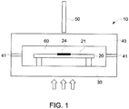
- FIG. 1 shows a resonator device 10 of an example of the present invention.
- the resonator device may be used in a transducer for various applications, such as to measure pressure, force, acceleration, the presence of a fluid etc.
- the resonator device comprises a resonator 20 provided on a diaphragm 30.
- the resonator 20 is enclosed by a cap 40 provided over it forming a hermetically sealed package.
- the cap 40 is bonded 41 to the diaphragm 30, such as by silicon fusion bonding, with a vacuum environment provided within the sealed package.
- the resonator 20 within the sealed package is excited or stimulated by applying electromagnetic radiation, such as infra-red or visible light, from outside the sealed package, in this example from a fibre 50, onto the resonator 20.
- the resonator device 10 may be interrogated by electromagnetic radiation as well.
- the resonator 20 and the inside surface of the cap 40 may form an optical cavity 60, such as a Fabry-Perot cavity between them.
- a force such as pressure acting on the outside surface of the diaphragm 30, changes the stiffness of the resonator 20 causing its resonant frequency to change.
- the resonant frequency may be determined, for example by analysing the interference fringe pattern of an interrogating electromagnetic signal applied to the optical cavity, such that the pressure acting on the outside surface of the diaphragm may be derived.
- the resonator device 10 may be stimulated and interrogated using only one fibre 50. Different wave lengths of electromagnetic radiation may be used to stimulate and interrogate respectively the device 10 using the same fibre 50. Alternatively or additionally, stimulation and interrogation may be 15 performed at different times.
- the resonator device may be made from silicon, such as single crystal silicon providing the advantages of no creep and no plasticity.
- MEMS technology may be used for fabrication.
- the resonator package 10 may be made by silicon fusion bonding the diaphragm 30, resonator 20 and cap 40 together to create a hermetic seal of the resonator cavity 60 and to simultaneously produce vacuum conditions inside the package 10 without requiring subsequent processing steps to evacuate the package.
- the electromagnetic stimulation 50 is applied extrinsically, the package does not need to be penetrated so that the evacuated 25 optical cavity 60 within the package is not compromised.
- the transducer of this example is especially suitable for use in harsh and high temperature environments such as downhole in oil and gas operations, in geothermal applications and aero-engines for example because of its robustness due to the use of a hermetically sealed package.
- Figure 2 is a top view of an example of a resonator 20.
- a resonator beam 21 is supported by two mesas 22 that are standing on the diaphragm 30.
- the resonator beam 21 shown in Figure 2 is attached to the mesas 22 via supports 23.
- any suitable resonator arrangement may be used, such as the one shown in side view of Figure 1 with the resonator beam 21 directly supported by the mesas 22.
- the resonator 20 is excited by applying electromagnetic stimulation via the fibre 50 to excite vertical vibrations by means of the photothermal effect.
- a target pad 24 with a surface arranged to absorb the electromagnetic stimulation is provided on the resonator beam 21, preferably in the centre.
- the target 24 may be coated with an electromagnetic radiation absorbing layer to enable its temperature to be changed more easily by the applied electromagnetic radiation,
- the optical target may comprise a shallow, opaque region such as by being heavily Boron doped to absorb more power from the electromagnetic stimulation which helps to reduce the power budget from the laser source.
- the target pad 24 is heated up by the electromagnetic stimulation and performs a deformation. When the electromagnetic 20 stimulation is turned off, the heat is then dissipated and the resonator beam 21 returns to its previous state.
- appropriate modulation pulses depending upon the particular circumstances, eg power of stimulating electromagnetic radiation, size of resonator beam 21, size of target pad 24 etc the resonator can be excited to an appropriate resonating mode.
- the target pad 24 may be relatively large, for example twice, five times or ten times larger than the fibre diameter. This enables the electromagnetic source 50 to be aligned easily with the target 24 such that active alignment is not required and provides robustness to protect against subsequent relative movement.
- the interrogating electromagnetic radiation applied from outside the hermetically sealed device 10 from the fibre 50 is partially reflected back from the internal surface of the cap 40 and partially dynamically modulated by the resonator beam 21 and then also reflected back to the fibre 50.
- Pressure applied to the external surface of the diaphragm 30 can then be derived by measuring the characteristics of the phase interference fringes from the reflected interrogating electromagnetic radiation through the optical cavity 60.
- the resonator 20 is arranged to maintain lateral dynamic balance and mass balance in a vertical direction, in this example by having a symmetrical structure. Alternatively or additionally this may be achieved by the resonator beam 21 being driven in the 3rd mode.
- the deflection of 10 the resonator determines the resolution of the interference fringes.
- the resonator of this example is designed to achieve a deflection of about 1 ⁇ 4 of the wavelength of the interrogating electromagnetic radiation (about 400nm for a 1550 nm laser) to provide relatively high level modulation without introducing severe straining stiffening thus achieving low non-linearity.
- the cap 40 is transparent to the electromagnetic radiation. This may for example be achieved by using an undoped or relatively low doped cap 40 or portion of the cap 40 through which the electromagnetic radiation is arranged to pass. This ensures that little or no power is absorbed 20 or reflected while the electromagnetic radiation is travelling through the cap 40.
- the resonator device may be provided with an integrated temperature sensor. Since the thickness of the cap 40 varies with temperature, by measuring the thermal expansion of the cap using the electromagnetic stimulation or interrogation signal, the temperature of the package may be determined, for example by using previous calibration using a look-up table, algorithm etc. A suitable cap thickness may be selected such that its "optical thickness" can be measured as a temperature signal. A temperature measurement enables resonator frequency changes to be compensated for temperature for enhanced accuracy.
- the device may also be used as a temperature sensor or multivariable sensor.
- Figure 3 shows the clear correspondence between applied pressure and resultant resonant frequency of the package illustrating the precision of results achieved from a resonator device which is also very robust and suitable for use in harsh environments, such as downhole, in aero-engines etc. Similar results are obtained when using the resonator device to measure other characteristics such as force, acceleration, fluid presence etc.
- FIG. 4 is a flow diagram of a method for fabricating a resonator device 10.
- a diaphragm wafer 30, a resonator wafer 20 and a cap wafer 40 are provided.
- they are bonded together, preferably by silicon fusion bonding, to form a hermetically sealed 10 package 10 with the resonator 20 enclosed by the diaphragm 30 and cap 40.
- electromagnetic radiation is arranged to be applied extrinsically to the sealed package 10 to stimulate and interrogate the resonator 20, for example via a fibre 50 connected to an appropriate source of electromagnetic radiation such as a laser.
- the resonator device 10 may be used in any appropriate transducer device, such as to measure pressure, force, acceleration, the presence of a fluid etc.
Landscapes
- Physics & Mathematics (AREA)
- General Physics & Mathematics (AREA)
- Chemical & Material Sciences (AREA)
- Engineering & Computer Science (AREA)
- Manufacturing & Machinery (AREA)
- Crystallography & Structural Chemistry (AREA)
- Analytical Chemistry (AREA)
- Acoustics & Sound (AREA)
- Measuring Fluid Pressure (AREA)
- Micromachines (AREA)
Claims (13)
- Resonatorvorrichtung (10) für einen Wandler, wobei die Resonatorvorrichtung (10) einen Resonator (20) umfasst, der auf einer Membran (30) mit einer Kappe (40) bereitgestellt ist, die den Resonator (20) umschließt und ein hermetisch abgedichtetes Gehäuse bildet, wobei der Resonator (20) ausgebildet ist, durch Anlegen von elektromagnetischer Stimulation angeregt zu werden, wobei die elektromagnetische Stimulation von außerhalb des hermetisch abgedichteten Gehäuses angelegt wird, wobei der Resonator (20) mit einem Ziel (24) zum Aufnehmen der elektromagnetischen Stimulation versehen ist, und dadurch gekennzeichnet, dass der Durchmesser des Ziels (24) größer als der Durchmesser einer Faser (50) ist, die ausgebildet ist, die elektromagnetische Stimulation an die Resonatorvorrichtung anzulegen.
- Resonatorvorrichtung (10) nach Anspruch 1, wobei mindestens ein Abschnitt der Kappe (40) für elektromagnetische Strahlung transparent ist.
- Resonatorvorrichtung (10) nach Anspruch 1 oder Anspruch 2, wobei ein optischer Hohlraum zwischen der Innenfläche der Kappe (40) und dem Resonator (20) gebildet ist und die Resonatorvorrichtung ausgebildet ist, durch Anlegen eines elektromagnetischen Signals in den optischen Hohlraum abgefragt zu werden, um eine Frequenzänderung des Resonators (20) abzuleiten.
- Resonatorvorrichtung (10) nach Anspruch 3, wobei die elektromagnetische Stimulation des Resonators (20) und das elektromagnetische Signal zum Abfragen der Resonatorvorrichtung (10) beide durch dieselbe Faser (50) angelegt werden.
- Resonatorvorrichtung (10) nach Anspruch 3 oder Anspruch 4, wobei die elektromagnetische Stimulation und das elektromagnetische Abfragesignal unterschiedliche Wellenlängen aufweisen.
- Resonatorvorrichtung (10) nach einem der vorstehenden Ansprüche, wobei der Resonator (20), die Membran (30) und die Kappe (40) jeweils aus Siliziumwafern gebildet sind, die miteinander verschmolzen sind, um ein evakuiertes hermetisch abgedichtetes Gehäuse zu erzeugen.
- Resonatorvorrichtung (10) nach einem der vorstehenden Ansprüche, wobei die gemessene thermische Ausdehnung oder Kontraktion der Kappendicke verwendet wird, um thermisch induzierte Resonatorfrequenzänderungen zu kompensieren.
- Resonatorvorrichtung (10) nach einem der vorstehenden Ansprüche, wobei der Durchmesser des Ziels (24) mindestens das Zehnfache des Durchmessers der Faser (50) beträgt, die ausgebildet ist, die elektromagnetische Stimulation anzulegen.
- Resonatorvorrichtung (10) nach einem der vorstehenden Ansprüche, wobei das Ziel (24) mit einer lichtabsorbierenden Schicht beschichtet ist.
- Druckwandler mit einer Resonatorvorrichtung (10) nach einem der vorstehenden Ansprüche.
- Beschleunigungssensor mit einer Resonatorvorrichtung (10) nach einem der vorstehenden Ansprüche.
- Kraftsensor mit einer Resonatorvorrichtung (10) nach einem der vorstehenden Ansprüche.
- Verfahren zum Fertigen einer Resonatorvorrichtung (10), wobei das Verfahren umfasst:Bereitstellen eines Membranwafers, eines Resonatorwafers und eines Kappenwafers;Verbinden der Wafer miteinander, um ein hermetisch abgedichtetes Gehäuse zu bilden, wobei der Resonator (20) von der Membran (30) und der Kappe (40) umschlossen ist;Ausbilden, um von außerhalb des hermetisch abgedichteten Gehäuses elektromagnetische Strahlung auf das hermetisch abgedichtete Gehäuse anzuwenden; undBereitstellen eines Ziels (24) am Resonator (20), um die elektromagnetische Strahlung aufzunehmen, die von außerhalb des hermetisch abgedichteten Gehäuses angelegt wird, wobei der Durchmesser des Ziels größer als der Durchmesser der Faser (50) ist, die ausgebildet ist, die elektromagnetische Stimulation auf die Resonatorvorrichtung anzulegen.
Applications Claiming Priority (2)
| Application Number | Priority Date | Filing Date | Title |
|---|---|---|---|
| GB1222630.4A GB2508908B (en) | 2012-12-14 | 2012-12-14 | Resonator device |
| PCT/US2013/075004 WO2014093817A1 (en) | 2012-12-14 | 2013-12-13 | Resonator device |
Publications (2)
| Publication Number | Publication Date |
|---|---|
| EP2932219A1 EP2932219A1 (de) | 2015-10-21 |
| EP2932219B1 true EP2932219B1 (de) | 2021-10-27 |
Family
ID=47630784
Family Applications (1)
| Application Number | Title | Priority Date | Filing Date |
|---|---|---|---|
| EP13814388.8A Active EP2932219B1 (de) | 2012-12-14 | 2013-12-13 | Resonatorvorrichtung |
Country Status (4)
| Country | Link |
|---|---|
| US (1) | US9998089B2 (de) |
| EP (1) | EP2932219B1 (de) |
| GB (1) | GB2508908B (de) |
| WO (1) | WO2014093817A1 (de) |
Families Citing this family (6)
| Publication number | Priority date | Publication date | Assignee | Title |
|---|---|---|---|---|
| GB2509105B (en) * | 2012-12-20 | 2017-02-22 | Oxsensis Ltd | Mechanical resonator sensor |
| US9671303B2 (en) | 2015-03-10 | 2017-06-06 | Ford Global Technologies, Llc | Method and system for laser pressure transducer |
| FR3088119B1 (fr) * | 2018-11-06 | 2020-11-06 | Commissariat Energie Atomique | Dispositif de mesure base sur une mesure optique dans une cavite opto-mecanique. |
| US11221266B2 (en) | 2019-05-22 | 2022-01-11 | Baker Hughes Oilfield Operations Llc | Automatic zero reset for a pressure transducer |
| CN110902640B (zh) * | 2019-12-11 | 2022-06-03 | 合肥工业大学 | 一种高灵敏度mems谐振式温度传感器芯片 |
| FR3162513B1 (fr) * | 2024-05-24 | 2026-05-01 | Safran | Capteur de pression résonant, ensemble de mesure et aéronef associés |
Citations (5)
| Publication number | Priority date | Publication date | Assignee | Title |
|---|---|---|---|---|
| US5090254A (en) * | 1990-04-11 | 1992-02-25 | Wisconsin Alumni Research Foundation | Polysilicon resonating beam transducers |
| US5747705A (en) * | 1996-12-31 | 1998-05-05 | Honeywell Inc. | Method for making a thin film resonant microbeam absolute |
| US20070236213A1 (en) * | 2006-03-30 | 2007-10-11 | Paden Bradley E | Telemetry method and apparatus using magnetically-driven mems resonant structure |
| US7499604B1 (en) * | 2004-12-12 | 2009-03-03 | Burns David W | Optically coupled resonant pressure sensor and process |
| CN101566506A (zh) * | 2008-04-22 | 2009-10-28 | 中国计量学院 | 一种基于微型桥谐振器的薄膜热电变换器的结构及制作方法 |
Family Cites Families (37)
| Publication number | Priority date | Publication date | Assignee | Title |
|---|---|---|---|---|
| US4329058A (en) | 1979-01-22 | 1982-05-11 | Rockwell International Corporation | Method and apparatus for a Fabry-Perot multiple beam fringe sensor |
| GB2115551B (en) | 1982-02-09 | 1985-11-13 | Itt Ind Ltd | Load sensor |
| GB2121953B (en) * | 1982-06-10 | 1985-09-04 | Itt Ind Ltd | Improvements in transducers |
| GB8323685D0 (en) | 1983-09-03 | 1983-10-05 | Gen Electric Co Plc | Monitoring displacement |
| GB8408383D0 (en) | 1984-03-31 | 1984-05-10 | Jackson D A | Optical pressure-sensing apparatus |
| GB8418914D0 (en) | 1984-07-25 | 1984-08-30 | Standard Telephones Cables Ltd | Transducer |
| GB8530809D0 (en) | 1985-12-13 | 1986-01-22 | Gen Electric Co Plc | Sensor |
| GB8610252D0 (en) * | 1986-04-26 | 1986-06-25 | Stc Plc | Remote sensor |
| GB8610253D0 (en) | 1986-04-26 | 1986-05-29 | Stc Plc | Resonator device |
| US4733561A (en) | 1986-07-21 | 1988-03-29 | The Foxboro Company | Self-oscillating, optical resonant sensor |
| GB2197069B (en) * | 1986-11-03 | 1990-10-24 | Stc Plc | Sensor device |
| US4942767A (en) | 1986-11-19 | 1990-07-24 | Massachusetts Institute Of Technology | Pressure transducer apparatus |
| US5265479A (en) | 1989-10-17 | 1993-11-30 | Lucas Industries Public Limited Company | Micro resonator |
| EP0460357A3 (en) | 1990-06-08 | 1992-07-29 | Landis & Gyr Betriebs Ag | Device for optical measurement of pressure differences |
| US5101664A (en) | 1990-10-15 | 1992-04-07 | United Technologies Corporation | Optical pressure transducer |
| FR2680574B1 (fr) * | 1991-08-23 | 1996-04-12 | Schlumberger Ind Sa | Microcapteur a poutre vibrante compense en temperature. |
| FI98095C (fi) | 1992-05-19 | 1997-04-10 | Vaisala Technologies Inc Oy | Fabry-Perot resonaattoriin perustuva optinen voima-anturi, jossa ilmaisimen osana toimii pyyhkäisevä Fabry-Perot resonaattori |
| GB9321398D0 (en) * | 1993-10-16 | 1993-12-08 | Lucas Ind Plc | Differential pressure transducer |
| US5500761A (en) | 1994-01-27 | 1996-03-19 | At&T Corp. | Micromechanical modulator |
| JP3304696B2 (ja) | 1995-04-17 | 2002-07-22 | 株式会社先進材料利用ガスジェネレータ研究所 | 光学式センサ |
| US6281976B1 (en) | 1997-04-09 | 2001-08-28 | The Texas A&M University System | Fiber optic fiber Fabry-Perot interferometer diaphragm sensor and method of measurement |
| CN1153054C (zh) | 1998-12-04 | 2004-06-09 | 塞德拉公司 | 布拉格光栅压力传感器 |
| FR2828560B1 (fr) * | 2001-08-09 | 2004-02-20 | Schlumberger Services Petrol | Capteur resonnant a excitation optique et dispositif de surveillance utilisant ce capteur |
| NO315177B1 (no) | 2001-11-29 | 2003-07-21 | Sinvent As | Optisk forskyvnings-sensor |
| US6894787B2 (en) * | 2001-12-21 | 2005-05-17 | Honeywell International Inc. | Optical pressure sensor |
| US6714007B2 (en) * | 2002-01-18 | 2004-03-30 | Honeywell International Inc. | Optically powered resonant integrated microstructure magnetic field gradient sensor |
| DE102004018408A1 (de) * | 2004-04-16 | 2005-11-03 | Robert Bosch Gmbh | Kapazitiver Drucksensor und Verfahren zur Herstellung |
| US7187453B2 (en) | 2004-04-23 | 2007-03-06 | Opsens Inc. | Optical MEMS cavity having a wide scanning range for measuring a sensing interferometer |
| US20050253283A1 (en) * | 2004-05-13 | 2005-11-17 | Dcamp Jon B | Getter deposition for vacuum packaging |
| EP1869737B1 (de) | 2005-03-16 | 2021-05-12 | Davidson Instruments, Inc. | Hochintensitäts-fabry-perot-sensor |
| US7622782B2 (en) * | 2005-08-24 | 2009-11-24 | General Electric Company | Pressure sensors and methods of making the same |
| US7490519B2 (en) * | 2005-09-30 | 2009-02-17 | General Electric Company | System and method for sensing differential pressure |
| EP2021747B1 (de) | 2006-04-26 | 2018-08-01 | Halliburton Energy Services, Inc. | Faseroptischer seismischer mems-sensor mit von schwenkbalken getragener masse |
| WO2008091645A1 (en) | 2007-01-24 | 2008-07-31 | Davidson Energy | Transducer for measuring environmental parameters |
| US7800190B2 (en) * | 2008-06-16 | 2010-09-21 | Honeywell International Inc. | Getter on die in an upper sense plate designed system |
| US20100189444A1 (en) * | 2009-01-27 | 2010-07-29 | General Electric Company | Optical mems device and remote sensing system utilizing the same |
| JP5118785B2 (ja) | 2011-04-12 | 2013-01-16 | パナソニック株式会社 | Mems圧力センサ |
-
2012
- 2012-12-14 GB GB1222630.4A patent/GB2508908B/en active Active
-
2013
- 2013-12-13 WO PCT/US2013/075004 patent/WO2014093817A1/en not_active Ceased
- 2013-12-13 EP EP13814388.8A patent/EP2932219B1/de active Active
- 2013-12-13 US US14/650,658 patent/US9998089B2/en active Active
Patent Citations (5)
| Publication number | Priority date | Publication date | Assignee | Title |
|---|---|---|---|---|
| US5090254A (en) * | 1990-04-11 | 1992-02-25 | Wisconsin Alumni Research Foundation | Polysilicon resonating beam transducers |
| US5747705A (en) * | 1996-12-31 | 1998-05-05 | Honeywell Inc. | Method for making a thin film resonant microbeam absolute |
| US7499604B1 (en) * | 2004-12-12 | 2009-03-03 | Burns David W | Optically coupled resonant pressure sensor and process |
| US20070236213A1 (en) * | 2006-03-30 | 2007-10-11 | Paden Bradley E | Telemetry method and apparatus using magnetically-driven mems resonant structure |
| CN101566506A (zh) * | 2008-04-22 | 2009-10-28 | 中国计量学院 | 一种基于微型桥谐振器的薄膜热电变换器的结构及制作方法 |
Also Published As
| Publication number | Publication date |
|---|---|
| EP2932219A1 (de) | 2015-10-21 |
| GB2508908B (en) | 2017-02-15 |
| US20160191011A1 (en) | 2016-06-30 |
| WO2014093817A1 (en) | 2014-06-19 |
| GB201222630D0 (en) | 2013-01-30 |
| US9998089B2 (en) | 2018-06-12 |
| GB2508908A (en) | 2014-06-18 |
Similar Documents
| Publication | Publication Date | Title |
|---|---|---|
| US9998089B2 (en) | Resonator device | |
| Lu et al. | Review of micromachined optical accelerometers: From mg to sub-μg | |
| CA2162168C (en) | Opto-electric-mechanical device or filter, process for making, and sensors made therefrom | |
| US7605391B2 (en) | Optically coupled resonator | |
| US7173713B2 (en) | Optical fiber sensors for harsh environments | |
| CN101608944B (zh) | 一种光纤振动传感头及其制作方法 | |
| US20050195402A1 (en) | Crystalline optical fiber sensors for harsh environments | |
| Zook et al. | Optically excited self-resonant microbeams | |
| ES2966309T3 (es) | Espectroscopio foto acústico con estructura vibratoria como detector de sonido | |
| Gao et al. | A wafer-level vacuum-packaged vertical resonant electric field microsensor | |
| JPS62273424A (ja) | 遠隔圧力センサ方式 | |
| Liu et al. | All-silica optical fiber Fabry-Perot Vibration Sensor based on MEMS and Laser Welding for High Temperature up to 800℃ | |
| WO2015012094A1 (ja) | 光干渉式センサ及びそれを用いた計測システム | |
| EP3663717A1 (de) | System und verfahren zur optischen anregung einer akustischen resonanz in resonator-gyroskopen | |
| US7443509B1 (en) | Optical and electronic interface for optically coupled resonators | |
| Busurin et al. | Micro-opto-electro-mechanical angular velocity transducer based on the optical tunneling effect | |
| CN102252753A (zh) | 基于光压效应的红外光子探测方法 | |
| CN116812855A (zh) | 一种微机械振子、f-p腔及微机械振子的制备方法 | |
| Jones et al. | Optical-fibre sensors using micromachined silicon resonant elements | |
| Zhou et al. | Calibration-Free, Split Accelerated Degradation Testing Platform Revealing the Long-Term Reliability of 2-D Micromirrors Without On-Chip Sensors | |
| Esashi et al. | Packaged micromechanical sensors | |
| Joshi | Recent Development in Applications of Optical MEMS: A Review | |
| CN110668391B (zh) | 一种具有应力释放功能的双端固支板式mems结构 | |
| KR101273303B1 (ko) | 열 효과를 이용한 마이크로 역학 진동자 기반의 압력센서 및 이를 이용한 압력 측정 방법 | |
| Luo et al. | Resonant pressure sensor with through-glass electrical interconnect based on SOI wafer technology |
Legal Events
| Date | Code | Title | Description |
|---|---|---|---|
| PUAI | Public reference made under article 153(3) epc to a published international application that has entered the european phase |
Free format text: ORIGINAL CODE: 0009012 |
|
| 17P | Request for examination filed |
Effective date: 20150714 |
|
| AK | Designated contracting states |
Kind code of ref document: A1 Designated state(s): AL AT BE BG CH CY CZ DE DK EE ES FI FR GB GR HR HU IE IS IT LI LT LU LV MC MK MT NL NO PL PT RO RS SE SI SK SM TR |
|
| AX | Request for extension of the european patent |
Extension state: BA ME |
|
| DAX | Request for extension of the european patent (deleted) | ||
| 17Q | First examination report despatched |
Effective date: 20160422 |
|
| STAA | Information on the status of an ep patent application or granted ep patent |
Free format text: STATUS: EXAMINATION IS IN PROGRESS |
|
| REG | Reference to a national code |
Ref country code: DE Ref legal event code: R079 Ref document number: 602013079824 Country of ref document: DE Free format text: PREVIOUS MAIN CLASS: G01L0009000000 Ipc: G01L0019000000 |
|
| RIC1 | Information provided on ipc code assigned before grant |
Ipc: G01K 7/32 20060101ALI20210319BHEP Ipc: G01L 9/00 20060101ALI20210319BHEP Ipc: G01L 19/04 20060101ALI20210319BHEP Ipc: G01L 19/00 20060101AFI20210319BHEP |
|
| GRAP | Despatch of communication of intention to grant a patent |
Free format text: ORIGINAL CODE: EPIDOSNIGR1 |
|
| STAA | Information on the status of an ep patent application or granted ep patent |
Free format text: STATUS: GRANT OF PATENT IS INTENDED |
|
| INTG | Intention to grant announced |
Effective date: 20210527 |
|
| GRAS | Grant fee paid |
Free format text: ORIGINAL CODE: EPIDOSNIGR3 |
|
| GRAA | (expected) grant |
Free format text: ORIGINAL CODE: 0009210 |
|
| STAA | Information on the status of an ep patent application or granted ep patent |
Free format text: STATUS: THE PATENT HAS BEEN GRANTED |
|
| AK | Designated contracting states |
Kind code of ref document: B1 Designated state(s): AL AT BE BG CH CY CZ DE DK EE ES FI FR GB GR HR HU IE IS IT LI LT LU LV MC MK MT NL NO PL PT RO RS SE SI SK SM TR |
|
| REG | Reference to a national code |
Ref country code: GB Ref legal event code: FG4D |
|
| REG | Reference to a national code |
Ref country code: CH Ref legal event code: EP |
|
| REG | Reference to a national code |
Ref country code: AT Ref legal event code: REF Ref document number: 1442206 Country of ref document: AT Kind code of ref document: T Effective date: 20211115 |
|
| REG | Reference to a national code |
Ref country code: DE Ref legal event code: R096 Ref document number: 602013079824 Country of ref document: DE |
|
| REG | Reference to a national code |
Ref country code: IE Ref legal event code: FG4D |
|
| REG | Reference to a national code |
Ref country code: LT Ref legal event code: MG9D |
|
| REG | Reference to a national code |
Ref country code: NL Ref legal event code: MP Effective date: 20211027 |
|
| REG | Reference to a national code |
Ref country code: AT Ref legal event code: MK05 Ref document number: 1442206 Country of ref document: AT Kind code of ref document: T Effective date: 20211027 |
|
| PG25 | Lapsed in a contracting state [announced via postgrant information from national office to epo] |
Ref country code: RS Free format text: LAPSE BECAUSE OF FAILURE TO SUBMIT A TRANSLATION OF THE DESCRIPTION OR TO PAY THE FEE WITHIN THE PRESCRIBED TIME-LIMIT Effective date: 20211027 Ref country code: LT Free format text: LAPSE BECAUSE OF FAILURE TO SUBMIT A TRANSLATION OF THE DESCRIPTION OR TO PAY THE FEE WITHIN THE PRESCRIBED TIME-LIMIT Effective date: 20211027 Ref country code: FI Free format text: LAPSE BECAUSE OF FAILURE TO SUBMIT A TRANSLATION OF THE DESCRIPTION OR TO PAY THE FEE WITHIN THE PRESCRIBED TIME-LIMIT Effective date: 20211027 Ref country code: BG Free format text: LAPSE BECAUSE OF FAILURE TO SUBMIT A TRANSLATION OF THE DESCRIPTION OR TO PAY THE FEE WITHIN THE PRESCRIBED TIME-LIMIT Effective date: 20220127 Ref country code: AT Free format text: LAPSE BECAUSE OF FAILURE TO SUBMIT A TRANSLATION OF THE DESCRIPTION OR TO PAY THE FEE WITHIN THE PRESCRIBED TIME-LIMIT Effective date: 20211027 |
|
| PG25 | Lapsed in a contracting state [announced via postgrant information from national office to epo] |
Ref country code: IS Free format text: LAPSE BECAUSE OF FAILURE TO SUBMIT A TRANSLATION OF THE DESCRIPTION OR TO PAY THE FEE WITHIN THE PRESCRIBED TIME-LIMIT Effective date: 20220227 Ref country code: SE Free format text: LAPSE BECAUSE OF FAILURE TO SUBMIT A TRANSLATION OF THE DESCRIPTION OR TO PAY THE FEE WITHIN THE PRESCRIBED TIME-LIMIT Effective date: 20211027 Ref country code: PT Free format text: LAPSE BECAUSE OF FAILURE TO SUBMIT A TRANSLATION OF THE DESCRIPTION OR TO PAY THE FEE WITHIN THE PRESCRIBED TIME-LIMIT Effective date: 20220228 Ref country code: PL Free format text: LAPSE BECAUSE OF FAILURE TO SUBMIT A TRANSLATION OF THE DESCRIPTION OR TO PAY THE FEE WITHIN THE PRESCRIBED TIME-LIMIT Effective date: 20211027 Ref country code: NO Free format text: LAPSE BECAUSE OF FAILURE TO SUBMIT A TRANSLATION OF THE DESCRIPTION OR TO PAY THE FEE WITHIN THE PRESCRIBED TIME-LIMIT Effective date: 20220127 Ref country code: NL Free format text: LAPSE BECAUSE OF FAILURE TO SUBMIT A TRANSLATION OF THE DESCRIPTION OR TO PAY THE FEE WITHIN THE PRESCRIBED TIME-LIMIT Effective date: 20211027 Ref country code: LV Free format text: LAPSE BECAUSE OF FAILURE TO SUBMIT A TRANSLATION OF THE DESCRIPTION OR TO PAY THE FEE WITHIN THE PRESCRIBED TIME-LIMIT Effective date: 20211027 Ref country code: HR Free format text: LAPSE BECAUSE OF FAILURE TO SUBMIT A TRANSLATION OF THE DESCRIPTION OR TO PAY THE FEE WITHIN THE PRESCRIBED TIME-LIMIT Effective date: 20211027 Ref country code: GR Free format text: LAPSE BECAUSE OF FAILURE TO SUBMIT A TRANSLATION OF THE DESCRIPTION OR TO PAY THE FEE WITHIN THE PRESCRIBED TIME-LIMIT Effective date: 20220128 Ref country code: ES Free format text: LAPSE BECAUSE OF FAILURE TO SUBMIT A TRANSLATION OF THE DESCRIPTION OR TO PAY THE FEE WITHIN THE PRESCRIBED TIME-LIMIT Effective date: 20211027 |
|
| REG | Reference to a national code |
Ref country code: DE Ref legal event code: R097 Ref document number: 602013079824 Country of ref document: DE |
|
| PG25 | Lapsed in a contracting state [announced via postgrant information from national office to epo] |
Ref country code: SM Free format text: LAPSE BECAUSE OF FAILURE TO SUBMIT A TRANSLATION OF THE DESCRIPTION OR TO PAY THE FEE WITHIN THE PRESCRIBED TIME-LIMIT Effective date: 20211027 Ref country code: SK Free format text: LAPSE BECAUSE OF FAILURE TO SUBMIT A TRANSLATION OF THE DESCRIPTION OR TO PAY THE FEE WITHIN THE PRESCRIBED TIME-LIMIT Effective date: 20211027 Ref country code: RO Free format text: LAPSE BECAUSE OF FAILURE TO SUBMIT A TRANSLATION OF THE DESCRIPTION OR TO PAY THE FEE WITHIN THE PRESCRIBED TIME-LIMIT Effective date: 20211027 Ref country code: MC Free format text: LAPSE BECAUSE OF FAILURE TO SUBMIT A TRANSLATION OF THE DESCRIPTION OR TO PAY THE FEE WITHIN THE PRESCRIBED TIME-LIMIT Effective date: 20211027 Ref country code: EE Free format text: LAPSE BECAUSE OF FAILURE TO SUBMIT A TRANSLATION OF THE DESCRIPTION OR TO PAY THE FEE WITHIN THE PRESCRIBED TIME-LIMIT Effective date: 20211027 Ref country code: DK Free format text: LAPSE BECAUSE OF FAILURE TO SUBMIT A TRANSLATION OF THE DESCRIPTION OR TO PAY THE FEE WITHIN THE PRESCRIBED TIME-LIMIT Effective date: 20211027 Ref country code: CZ Free format text: LAPSE BECAUSE OF FAILURE TO SUBMIT A TRANSLATION OF THE DESCRIPTION OR TO PAY THE FEE WITHIN THE PRESCRIBED TIME-LIMIT Effective date: 20211027 |
|
| REG | Reference to a national code |
Ref country code: CH Ref legal event code: PL |
|
| PLBE | No opposition filed within time limit |
Free format text: ORIGINAL CODE: 0009261 |
|
| STAA | Information on the status of an ep patent application or granted ep patent |
Free format text: STATUS: NO OPPOSITION FILED WITHIN TIME LIMIT |
|
| REG | Reference to a national code |
Ref country code: BE Ref legal event code: MM Effective date: 20211231 |
|
| GBPC | Gb: european patent ceased through non-payment of renewal fee |
Effective date: 20220127 |
|
| 26N | No opposition filed |
Effective date: 20220728 |
|
| PG25 | Lapsed in a contracting state [announced via postgrant information from national office to epo] |
Ref country code: LU Free format text: LAPSE BECAUSE OF NON-PAYMENT OF DUE FEES Effective date: 20211213 Ref country code: IE Free format text: LAPSE BECAUSE OF NON-PAYMENT OF DUE FEES Effective date: 20211213 Ref country code: GB Free format text: LAPSE BECAUSE OF NON-PAYMENT OF DUE FEES Effective date: 20220127 Ref country code: AL Free format text: LAPSE BECAUSE OF FAILURE TO SUBMIT A TRANSLATION OF THE DESCRIPTION OR TO PAY THE FEE WITHIN THE PRESCRIBED TIME-LIMIT Effective date: 20211027 |
|
| PG25 | Lapsed in a contracting state [announced via postgrant information from national office to epo] |
Ref country code: SI Free format text: LAPSE BECAUSE OF FAILURE TO SUBMIT A TRANSLATION OF THE DESCRIPTION OR TO PAY THE FEE WITHIN THE PRESCRIBED TIME-LIMIT Effective date: 20211027 Ref country code: BE Free format text: LAPSE BECAUSE OF NON-PAYMENT OF DUE FEES Effective date: 20211231 |
|
| PG25 | Lapsed in a contracting state [announced via postgrant information from national office to epo] |
Ref country code: LI Free format text: LAPSE BECAUSE OF NON-PAYMENT OF DUE FEES Effective date: 20211231 Ref country code: CH Free format text: LAPSE BECAUSE OF NON-PAYMENT OF DUE FEES Effective date: 20211231 |
|
| PG25 | Lapsed in a contracting state [announced via postgrant information from national office to epo] |
Ref country code: HU Free format text: LAPSE BECAUSE OF FAILURE TO SUBMIT A TRANSLATION OF THE DESCRIPTION OR TO PAY THE FEE WITHIN THE PRESCRIBED TIME-LIMIT; INVALID AB INITIO Effective date: 20131213 |
|
| PG25 | Lapsed in a contracting state [announced via postgrant information from national office to epo] |
Ref country code: CY Free format text: LAPSE BECAUSE OF FAILURE TO SUBMIT A TRANSLATION OF THE DESCRIPTION OR TO PAY THE FEE WITHIN THE PRESCRIBED TIME-LIMIT Effective date: 20211027 |
|
| P01 | Opt-out of the competence of the unified patent court (upc) registered |
Effective date: 20230526 |
|
| PG25 | Lapsed in a contracting state [announced via postgrant information from national office to epo] |
Ref country code: MK Free format text: LAPSE BECAUSE OF FAILURE TO SUBMIT A TRANSLATION OF THE DESCRIPTION OR TO PAY THE FEE WITHIN THE PRESCRIBED TIME-LIMIT Effective date: 20211027 |
|
| PG25 | Lapsed in a contracting state [announced via postgrant information from national office to epo] |
Ref country code: MT Free format text: LAPSE BECAUSE OF FAILURE TO SUBMIT A TRANSLATION OF THE DESCRIPTION OR TO PAY THE FEE WITHIN THE PRESCRIBED TIME-LIMIT Effective date: 20211027 |
|
| PG25 | Lapsed in a contracting state [announced via postgrant information from national office to epo] |
Ref country code: TR Free format text: LAPSE BECAUSE OF FAILURE TO SUBMIT A TRANSLATION OF THE DESCRIPTION OR TO PAY THE FEE WITHIN THE PRESCRIBED TIME-LIMIT Effective date: 20211027 |
|
| PGFP | Annual fee paid to national office [announced via postgrant information from national office to epo] |
Ref country code: DE Payment date: 20251126 Year of fee payment: 13 |
|
| PGFP | Annual fee paid to national office [announced via postgrant information from national office to epo] |
Ref country code: IT Payment date: 20251119 Year of fee payment: 13 |
|
| PGFP | Annual fee paid to national office [announced via postgrant information from national office to epo] |
Ref country code: FR Payment date: 20251120 Year of fee payment: 13 |
|
| REG | Reference to a national code |
Ref country code: DE Ref legal event code: R081 Ref document number: 602013079824 Country of ref document: DE Owner name: BAKER HUGHES HOLDINGS LLC (N. D. GES. D. STAAT, US Free format text: FORMER OWNER: GENERAL ELECTRIC COMPANY, SCHENECTADY, NY, US |