EP2932217B1 - Device with a torque sensor arrangement and a steering angle sensor arrangement for a motor vehicle, and motor vehicle - Google Patents
Device with a torque sensor arrangement and a steering angle sensor arrangement for a motor vehicle, and motor vehicle Download PDFInfo
- Publication number
- EP2932217B1 EP2932217B1 EP13811854.2A EP13811854A EP2932217B1 EP 2932217 B1 EP2932217 B1 EP 2932217B1 EP 13811854 A EP13811854 A EP 13811854A EP 2932217 B1 EP2932217 B1 EP 2932217B1
- Authority
- EP
- European Patent Office
- Prior art keywords
- disposed
- stator
- magnetic
- flux
- circuit board
- Prior art date
- Legal status (The legal status is an assumption and is not a legal conclusion. Google has not performed a legal analysis and makes no representation as to the accuracy of the status listed.)
- Active
Links
- 230000004907 flux Effects 0.000 claims description 110
- 239000004020 conductor Substances 0.000 claims description 55
- 230000005540 biological transmission Effects 0.000 claims description 42
- 230000033001 locomotion Effects 0.000 claims description 13
- 238000012216 screening Methods 0.000 claims 1
- 230000009977 dual effect Effects 0.000 description 8
- 238000001514 detection method Methods 0.000 description 7
- 230000002093 peripheral effect Effects 0.000 description 7
- 238000005516 engineering process Methods 0.000 description 2
- 239000010408 film Substances 0.000 description 2
- 238000004519 manufacturing process Methods 0.000 description 2
- 238000001465 metallisation Methods 0.000 description 2
- 238000000034 method Methods 0.000 description 2
- 239000010409 thin film Substances 0.000 description 2
- 238000003466 welding Methods 0.000 description 2
- 230000000712 assembly Effects 0.000 description 1
- 238000000429 assembly Methods 0.000 description 1
- 238000004364 calculation method Methods 0.000 description 1
- 230000001419 dependent effect Effects 0.000 description 1
- 230000000694 effects Effects 0.000 description 1
- 238000005304 joining Methods 0.000 description 1
- 230000005415 magnetization Effects 0.000 description 1
- 239000000463 material Substances 0.000 description 1
- 239000002184 metal Substances 0.000 description 1
- 238000005476 soldering Methods 0.000 description 1
Images


Classifications
-
- B—PERFORMING OPERATIONS; TRANSPORTING
- B62—LAND VEHICLES FOR TRAVELLING OTHERWISE THAN ON RAILS
- B62D—MOTOR VEHICLES; TRAILERS
- B62D15/00—Steering not otherwise provided for
- B62D15/02—Steering position indicators ; Steering position determination; Steering aids
- B62D15/021—Determination of steering angle
- B62D15/0215—Determination of steering angle by measuring on the steering column
-
- B—PERFORMING OPERATIONS; TRANSPORTING
- B62—LAND VEHICLES FOR TRAVELLING OTHERWISE THAN ON RAILS
- B62D—MOTOR VEHICLES; TRAILERS
- B62D6/00—Arrangements for automatically controlling steering depending on driving conditions sensed and responded to, e.g. control circuits
- B62D6/08—Arrangements for automatically controlling steering depending on driving conditions sensed and responded to, e.g. control circuits responsive only to driver input torque
- B62D6/10—Arrangements for automatically controlling steering depending on driving conditions sensed and responded to, e.g. control circuits responsive only to driver input torque characterised by means for sensing or determining torque
-
- G—PHYSICS
- G01—MEASURING; TESTING
- G01D—MEASURING NOT SPECIALLY ADAPTED FOR A SPECIFIC VARIABLE; ARRANGEMENTS FOR MEASURING TWO OR MORE VARIABLES NOT COVERED IN A SINGLE OTHER SUBCLASS; TARIFF METERING APPARATUS; MEASURING OR TESTING NOT OTHERWISE PROVIDED FOR
- G01D5/00—Mechanical means for transferring the output of a sensing member; Means for converting the output of a sensing member to another variable where the form or nature of the sensing member does not constrain the means for converting; Transducers not specially adapted for a specific variable
- G01D5/12—Mechanical means for transferring the output of a sensing member; Means for converting the output of a sensing member to another variable where the form or nature of the sensing member does not constrain the means for converting; Transducers not specially adapted for a specific variable using electric or magnetic means
- G01D5/14—Mechanical means for transferring the output of a sensing member; Means for converting the output of a sensing member to another variable where the form or nature of the sensing member does not constrain the means for converting; Transducers not specially adapted for a specific variable using electric or magnetic means influencing the magnitude of a current or voltage
- G01D5/142—Mechanical means for transferring the output of a sensing member; Means for converting the output of a sensing member to another variable where the form or nature of the sensing member does not constrain the means for converting; Transducers not specially adapted for a specific variable using electric or magnetic means influencing the magnitude of a current or voltage using Hall-effect devices
- G01D5/145—Mechanical means for transferring the output of a sensing member; Means for converting the output of a sensing member to another variable where the form or nature of the sensing member does not constrain the means for converting; Transducers not specially adapted for a specific variable using electric or magnetic means influencing the magnitude of a current or voltage using Hall-effect devices influenced by the relative movement between the Hall device and magnetic fields
-
- G—PHYSICS
- G01—MEASURING; TESTING
- G01L—MEASURING FORCE, STRESS, TORQUE, WORK, MECHANICAL POWER, MECHANICAL EFFICIENCY, OR FLUID PRESSURE
- G01L3/00—Measuring torque, work, mechanical power, or mechanical efficiency, in general
- G01L3/02—Rotary-transmission dynamometers
- G01L3/04—Rotary-transmission dynamometers wherein the torque-transmitting element comprises a torsionally-flexible shaft
- G01L3/10—Rotary-transmission dynamometers wherein the torque-transmitting element comprises a torsionally-flexible shaft involving electric or magnetic means for indicating
- G01L3/101—Rotary-transmission dynamometers wherein the torque-transmitting element comprises a torsionally-flexible shaft involving electric or magnetic means for indicating involving magnetic or electromagnetic means
- G01L3/104—Rotary-transmission dynamometers wherein the torque-transmitting element comprises a torsionally-flexible shaft involving electric or magnetic means for indicating involving magnetic or electromagnetic means involving permanent magnets
-
- G—PHYSICS
- G01—MEASURING; TESTING
- G01L—MEASURING FORCE, STRESS, TORQUE, WORK, MECHANICAL POWER, MECHANICAL EFFICIENCY, OR FLUID PRESSURE
- G01L5/00—Apparatus for, or methods of, measuring force, work, mechanical power, or torque, specially adapted for specific purposes
- G01L5/22—Apparatus for, or methods of, measuring force, work, mechanical power, or torque, specially adapted for specific purposes for measuring the force applied to control members, e.g. control members of vehicles, triggers
- G01L5/221—Apparatus for, or methods of, measuring force, work, mechanical power, or torque, specially adapted for specific purposes for measuring the force applied to control members, e.g. control members of vehicles, triggers to steering wheels, e.g. for power assisted steering
Definitions
- the invention relates to a device for a motor vehicle, having a torque sensor device for detecting a torque applied to a steering shaft of the motor vehicle, and having a steering angle sensor device for detecting a current steering angle of the steering shaft, wherein the torque sensor device comprises a magnetic stator for conducting magnetic flux of a magnet towards at least one flux guide and thereby to at least one magnetic sensor of the torque sensor device is formed and two axially staggered stator having each having a radially extending annular edge element, and wherein the steering angle sensor means at least one rotation transmission element with a Permanent magnet and a magnetic field detector for detecting a rotational movement of the rotation transmission member, wherein the at least one rotation transmission element with the Perman in which the steering angle sensor device has a rotor with a tooth structure and the rotation transmission element is designed as a gear which is engageable with the tooth structure of the rotor and by means of which a rotational movement of the rotor in a rotational movement of the permanent magnet transferable is, wherein the steering angle sensor
- Torque sensor devices for detecting a torque applied to a steering shaft of a motor vehicle are already known in the art. Such torque sensor devices can be used for example in electric steering systems.
- a torque sensor device is known from the document, for example US 2004/0194560 A1 as well as from the publication DE 102 40 049 A1 known.
- the torque sensor device is attached to two opposite in the axial direction shaft parts or partial waves of the steering shaft, which via a torsion bar are connected together.
- a magnet such as a ring magnet
- a holder is mounted with a magnetic stator, which is opposite to the permanent magnet in the radial direction over a small air gap.
- the magnetic flux of the magnet is directed towards a first and a second flux guide, which then deliver the magnetic flux to a magnetic sensor - for example a Hall sensor.
- the magnetic sensor is located between the two flux conductors, as for example in the Fig. 7 and 8th of the document US 2004/0194560 A1 is clearly recognizable.
- Such a torque sensor device is also known from the document DE 10 2007 043 502 A1 known.
- steering angle sensor devices which serve to detect the current steering angle of the steering shaft are known from the prior art.
- Such a device is for example from the document DE 10 2008 011 448 A1 to be known as known.
- a rotational movement of the steering shaft is transmitted here via a gear on a smaller gear, which carries a magnet.
- the rotation of the smaller gear is then detected using a magnetic sensor.
- the interest here is directed to devices in which the torque sensor device on the one hand and the steering angle sensor device on the other hand are integrally formed as a common structural unit.
- a device with a torque sensor and a rotation angle sensor is for example from the document DE 10 2010 033 769 A1 known.
- Another device with a torque sensor and a rotation angle sensor is from the document WO 2012/025683 A1 known.
- a gear transmission of the rotation angle sensor is arranged in the form of a worm drive in the axial direction between the edge elements of the stator of the torque sensor.
- a major challenge is to minimize the overall height of the device in the axial direction.
- the gearwheels (rotation transmission elements) of the steering angle sensor require relatively much space in the axial direction.
- An inventive device for a motor vehicle comprises a torque sensor device, which is designed to detect a torque applied to a steering shaft of the motor vehicle, and a steering angle sensor device, which is designed to detect the current steering angle of the steering shaft.
- the torque sensor device has a magnetic stator for directing magnetic flux from a magnet at least one flux guide and thereby formed to at least one magnetic sensor.
- the stator comprises two offset in the axial direction of each other arranged stator parts, each having a radially extending, annular edge element.
- the steering angle sensor device includes at least one rotation transmitting member (for example, a gearwheel) having a permanent magnet and a magnetic field detector for detecting rotational movement of the rotation transmitting member. On the rotation transmission element, a rotational movement of the steering shaft can be transmitted.
- the at least one rotation transmission element with the permanent magnet are arranged in the axial direction between the edge elements.
- the essential component of the steering angle sensor device namely the at least one rotational transmission element with its permanent magnet, not axially outside the stator but in the axial direction between the two stator parts or between the respective edge elements.
- the essential component of the steering angle sensor device namely the at least one rotational transmission element with its permanent magnet
- At constant axial distance between the stator thus reduces the axial height or the axial extent of the entire device compared to the prior art or compared to embodiments in which the rotation transmission element and its permanent magnet is arranged axially offset from the stator. It is thus a total in the axial direction very compact and space-saving integrated device created, which is designed both for detecting the torque and for detecting the steering angle.
- the at least one rotational transmission element is preferably in mutual operative connection with a rotor which is connected to one of the shaft parts.
- the rotary motion of the steering shaft can then be transmitted to the smaller rotational transmission element in its diameter via the rotor, and the rotational movement of the rotational transmission element can be detected by the magnetic field detector and the steering angle can be determined therefrom.
- the at least one rotation transmission element is preferably formed as a gear with a circumferential tooth structure, which is in engagement with a rotor which is rotatably connected to the steering shaft and has a circumferential tooth structure.
- the rotor may be arranged on a holder on which also the magnetic stator is mounted.
- the said magnet from which the magnetic flux is conducted via the stator as far as the flux guide and thereby to the magnetic sensor, can be connected, for example, to a first shaft part of the steering shaft.
- the magnetic stator on the other hand can be arranged on the said holder and rotatably connected thereto, which can be connected to a second shaft portion of the steering shaft.
- the two shaft parts can be coupled to each other in particular via a torsion bar.
- a slider can be used for the holder, which is designed to support the at least one flux guide, in which case the holder is rotatably arranged with the stator relative to the slider and thus relative to the flux guide.
- the at least one rotation transmission element is arranged with its permanent magnet at least partially in mutual axial overlap with the edge elements of the stator. This means that a projection of the rotation transmission element in the axial direction exists on the two edge elements.
- At least one rotational transmission element can be arranged with its associated permanent magnet offset in the radial direction to the edge elements. This in turn means that there is no axial projection of the rotation transmission element on the two edge elements of the stator.
- This embodiment has the advantage that crosstalk between the permanent magnet and the magnetic sensor of the torque sensor device via the magnetic stator can be prevented. Thus, errors in the detection of the torque can be prevented.
- the axial height is further reduced when the magnetic field detector is arranged on a printed circuit board, which is arranged axially between the two edge elements or axially between the stator and in particular also parallel to the edge elements.
- the two stator parts each have a radially extending or radially outwardly facing, annular and in particular flange-like and an axial edge of the respective stator part forming edge element.
- These edge elements are thus perpendicular to the axis of rotation of the steering shaft and the device and parallel to each other.
- the respective edge elements can each protrude a plurality of circumferentially distributed tooth elements arranged in the axial direction.
- the tooth elements of a stator are then arranged alternately distributed with the tooth elements of the other stator in the circumferential direction, so that the Tooth elements of a stator part extending axially into respective spaces between the tooth elements of the other stator.
- the flange-like edge elements preferably overlap one another in the axial direction, and the respective tooth elements preferably point axially in opposite directions.
- the annular edge elements serve to transmit the magnetic flux to the respective flux guide.
- a plate-shaped receiving region of the flux guide is preferably arranged at a very small distance from the flange-like edge element of the respective stator part.
- the tooth elements serve to receive the magnetic flux from the magnet, which is attached to one of the shaft parts.
- the permanent magnet of the rotation transmission element is arranged eccentrically in the axial direction between the two edge elements.
- the at least one magnetic sensor of the torque sensor device is preferably arranged axially in the middle between the two stator parts or the respective edge elements. This means that the at least one magnetic sensor is located at the same axial distance from the two edge elements.
- the permanent magnet of the rotation transmission element is preferably formed in this embodiment or surface magnetized such that it provides a magnetic field with the same field strength at the respective edge elements of the stator. The magnetic field is thus equal to the respective axial height of the two edge elements, so that cancel these magnetic fields of the permanent magnet to the mutual edge elements mutually.
- an influence of the magnetic flux is prevented, which is passed over the stator to the magnetic sensor. Errors in the detection of the torque can thus be prevented.
- the magnet of the rotation transmission element can be arranged axially in the middle between the two stator parts or the respective edge elements, so that the magnetic sensor of the torque sensor device and the magnetic field detector of the steering angle sensor device lie axially off-center.
- the two flux conductors are preferably arranged asymmetrically with respect to a plane of symmetry or center plane between the mutual edge elements of the stator parts.
- the one flux conductor can lie completely axially within the stator and thus axially between the edge elements, while the other flux conductor can be arranged at least with its reception region axially outside the stator or axially offset therefrom.
- Such an arrangement of the permanent magnet axially in the middle between the Edge elements has the advantage that the field strength of the magnetic field at the two edge elements is the same even with a "normal" permanent magnet without a special surface magnetization, so that no crosstalk between the two sensor types takes place.
- the two flux conductors can be the same components or they can also be designed differently.
- a shield for magnetic fields can also be arranged axially between the permanent magnet of the rotation transmission element on the one hand and at least one of the edge elements on the other hand.
- a shield may in particular be provided in the form of a shielding plate which extends parallel to the printed circuit board.
- the shield has the advantage that crosstalk between the two sensor parts via the stator can be effectively minimized. If appropriate, it can also be formed by a metallization of the printed circuit board itself or can be a component that is separate from the printed circuit board.
- the steering angle sensor device preferably comprises a rotor with a tooth structure.
- the rotation transmission member may be formed as a gear which is engageable with the tooth structure of the rotor and by means of which a rotational movement of the rotor and thus the steering shaft is transmitted in a rotational movement of the permanent magnet.
- the rotor is molded with its circumferential tooth structure directly to the said holder, on which the stator is arranged and which is connected to one of the shaft parts of the steering shaft. This eliminates an additional gear as an independent part, as well as the associated joining process of the rotor on the holder.
- This one-piece design of the rotor with the holder also results in an improved concentricity of the tooth elements.
- the at least one magnetic sensor of the torque sensor device is designed as an SMD component (surface-mounted device), which is arranged on a printed circuit board, namely in particular a printed circuit board common to the torque sensor device and the steering angle device, to which the magnetic field detector of the steering angle sensor device is also attached is appropriate.
- the at least one flux guide preferably has a tab which is arranged in mutual overlap with the magnetic sensor. While in the prior art due to the design of the flux guide of the magnetic sensor as a THT device (Throuh-hole technology) must be formed is proposed in this embodiment, form the magnetic sensor as an SMD component and the flux guide to design such that it has a, in particular extending in the radial direction, tab in mutual overlap with the Magnetic sensor is arranged.
- All components can be mounted as SMD components on the circuit board in a common manufacturing step, so that overall the manufacturing cost significantly reduced compared to the prior art.
- SMD components can also be made particularly flat, the size of the device in the direction perpendicular to the printed circuit board, in particular in the axial direction, can be further reduced.
- the circuit board is arranged axially between the two edge elements of the stator.
- the tab of the flux guide is an axial or a radial or pointing in the radial direction tab, which is arranged in mutual axial overlap with the magnetic sensor.
- the tab can therefore be a radial tab which points in the radial direction.
- the tab may also be provided that the tab is directed substantially in the axial direction and thus oriented axially, without having a special radial section.
- a mutual overlap between the tab and the magnetic sensor is then given, namely in particular in the axial direction or alternatively in the radial direction, depending on the orientation of the circuit board.
- the at least one flux guide has a plate-shaped receiving region arranged in mutual axial overlap with the stator for receiving the magnetic flux from the stator. Then, the flap extending parallel to the receiving region can be arranged offset in the axial direction to the receiving region.
- the radial lug of the flux guide is connected via a web or a bridge element to the receiving region, wherein the web is angled, in particular perpendicular, arranged both to the receiving region and to the tab.
- the flux conductor is preferably formed integrally in one piece, so that the reception area on the one hand and the web and the radial tab on the other hand are integrally formed with each other.
- the radial tab is arranged offset in the axial direction to the receiving region of the flux guide, on the one hand the receiving area can be arranged at a very small distance from the stator and on the other hand, the tab at a very small distance from the magnetic sensor, so that a reliable transmission of the magnetic flux from Stator is guaranteed to the magnetic sensor.
- the at least one flux guide can - similar to the stator - from a magnetic, z. B. soft magnetic, material may be formed.
- the torque sensor device may also have two flux guides, each with at least one said tab, which are arranged on opposite sides of the circuit board.
- the respective tabs can be arranged in mutual, in particular axial, overlap with the magnetic sensor.
- the magnetic sensor is arranged quasi as a sandwich element between the tab of the one flux conductor on the one hand and the tab of the other flux conductor on the other hand and overlaps the two tabs, in particular in the axial direction.
- the circuit board may have a recess formed under the magnetic sensor for the tab of the flux guide.
- the recess is preferably a through hole in the circuit board.
- the tab of said flux guide can then extend into the recess of the printed circuit board, in particular axially. In this way, the axial distance between the magnetic sensor or its back, on the one hand, and the tab of the flux guide, on the other hand, can be minimized and the transmission effect optimized. In addition, thus additionally reduces the axial height.
- the printed circuit board can also be designed in the form of a thin film as a so-called flex printed circuit board. This then preferably has a thickness of less than 0.2 mm, so that the magnetic flux can be transmitted through this film, without specifically a through hole must be provided. Thus, an effective flow transfer to the Magnetic sensor can be made possible by that flux conductor, which is located on the back of the circuit board.
- the magnetic flux can therefore be tapped with a total of two flux conductors at the respective edge elements of the stator and passed over the respective narrow tabs to the magnetic sensor and concentrated there.
- the tabs preferably extend to close to the top and bottom of the magnetic sensor zoom in order to obtain a very narrow air gap.
- said recess may be provided in the circuit board below the magnetic sensor, which is preferably formed as a through hole in the circuit board.
- the torque sensor device can also have two magnetic sensors designed as SMD components, each for detecting the magnetic flux, and the at least one flux guide can have two, preferably radial, tabs arranged in a common radial plane, each in mutual, in particular axial, overlap are arranged with one of the magnetic sensors.
- At least one magnetic sensor of the torque sensor device can be designed as a dual sensor with two integrated sensor elements, which are integrated in the SMD component and can detect the magnetic flux separately. With such a dual magnetic sensor, additional redundancy with respect to the detection of the torque can be made possible and / or the torque sensor device can make do with only a single magnetic sensor, which includes two integrated sensor elements.
- At least one of these magnetic sensors can be designed as a dual sensor with two sensor elements.
- both magnetic sensors can be designed as dual sensors.
- the torque sensor device comprises only one magnetic sensor, it can be designed as a dual sensor with two sensor elements for separate detection of the magnetic flux.
- the number of magnetic sensors used corresponds to the number of tabs used in a single flux guide.
- Each magnetic sensor is thus assigned in each case a tab of the at least one flux guide.
- the invention also relates to a motor vehicle with a device according to the invention.
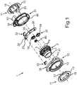
- An in Fig. 1 shown and designated overall by 1 device comprises both a torque sensor device and a steering angle sensor device.
- the torque sensor device is used to measure a torque applied to a steering shaft of a motor vehicle.
- the steering angle sensor device is used to detect the current steering angle of the Steering shaft.
- the device 1 is designed as an integral unit, so that an integral sensor device is provided, which is designed both for detecting the torque and for measuring the steering angle.
- the steering shaft of the vehicle includes two shaft parts, which are interconnected via a torsion bar, not shown in the figures.
- a holder 2 On one of the shaft parts, a holder 2 is mounted rotatably, while on the other shaft part in the figure, not shown magnet - namely permanent magnet, for example in the form of a ring magnet - is held against rotation.
- the holder 2 may be an integrally formed plastic part and / or a cast component.
- the holder 2 can also be provided with a sleeve 47, for example made of metal, or other fastening elements such as tabs, hooks, clips and the like in order to fasten the holder 2 to the associated shaft part.
- the components of the torque sensor device are essentially: the named permanent magnet, a magnetic stator 11 with two identical stator parts 10, 17, two flux conductors 32, 33 and a magnetic sensor 27, which is placed on a printed circuit board 28.
- the steering angle sensor device includes two magnetic field detectors or magnetic sensors 29, 30, a gearbox 37 with rotational transmission elements, which are designed as gearwheels 38, 39, 40, and a rotor 15, which is molded onto the holder 2.
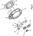
- the holder 2 comprises, as in particular from Fig. 2 shows two axially juxtaposed cylindrical regions, namely on the one hand a first cylindrical axial portion 3 and a staggered in the axial direction and concentric with the first region 3 and a slightly smaller diameter having second axial region 4.
- the first axial region 3 is above a Variety of circumferentially distributed, strut-shaped or spoke-shaped connecting elements 5 connected to the second axial region 4. Between the connecting elements 5 radial recesses 6 are formed, which are through holes.
- the first axial region 3 has two axial marginal edges, namely on the one hand a first outer peripheral edge 7 and on the other hand a second axial peripheral edge 8, which faces the second axial region 4.
- a plurality of axial pins or bolts 9 are formed, which protrude as axial extensions in the axial direction parallel to each other from the edge 7.
- the holder 2 is connected to a first stator 10 of the total designated 11 stator.
- the device 1 also includes a housing 12, which also has the function of a slider.
- the housing 12 has an inner sleeve 13 which is annularly formed and in which the first axial portion 3 of the holder 2 is received, so that the outer periphery of the first portion 3 of the holder 2 can slide on an inner periphery of the sleeve 13.
- the first axial region 3 of the holder 2 is inserted into the sleeve 13 up to a flange 14 of the holder 2, which is formed by a rotor 15 having a tooth structure 16.
- the rotor 15 with the tooth structure 16 is molded onto the first axial region 3.
- stator 11 additionally has a second stator part 17.
- Each stator part 10, 17 is formed in one piece and has an annular, flange-like and radially outwardly extending edge element 18 and 19, as well as a plurality of tooth elements 20 and 21.
- the tooth elements 20, 21 are of the respective Edge element 18, 19 in the axial direction, in the direction of the first axial region 3 of the holder 2 out.
- the tooth elements 20, 21 thus extend in the axial direction approximately parallel to an axis of rotation of the steering shaft.
- the two stator parts 10, 17 are formed the same, so that the number of tooth elements 20 of the first stator 10 is equal to the number of tooth elements 21 of the second stator 17.
- the stator part 17 is attached to the second axial region 4 of the holder 2, so that the tooth elements 21 are inserted axially through the recesses 6 between the connecting elements 5 and on an inner circumference of the first axial region 3 of the holder 2 are supported.
- the tooth elements 21 are arranged in the interior of the first axial region 3 of the holder 2, so that only the edge element 19 projects radially outwardly and at the axial peripheral edge 8 of the first axial Region 3 of the holder 2 is axially supported.
- the free ends of the pins 22 can be transformed and thus processed into rivet heads to secure fit of the stator 17 to the holder 2 to ensure.
- the other stator part 10 is fastened to the holder 2 such that the tooth elements 20 are inserted into the interior of the first axial region 3 of the holder 2 from the axial end face of the holder 2 opposite the stator part 17 or from the side of the peripheral edge 7.
- the tooth elements 20 slide on the inner circumference of the cylindrical portion 3.
- the tooth elements 20 are each between two adjacent tooth elements 21 of the other stator 17 and lie against the inner circumference of the region 3.
- the stator 10 has a plurality of tabs 25, in each of which a passage opening 26 is formed. Through these passage openings 26, the corresponding pins 9 are inserted through, which are formed on the peripheral edge 7 of the holder 2. The free ends of these pins 9 are formed into rivet heads and thus ensures a secure attachment of the stator on the holder 2.
- the two stator parts 10, 17 can be fixed to the holder 2 in a wide variety of ways.
- the combination of pins 9 and 22 and through holes 26 and 23 represents only an exemplary embodiment. It is also possible, for example, to fix the stator parts 10, 17 on the holder 2 via retaining rings, which by laser welding or ultrasonic welding to the holder 2 are fixed.
- the torque sensor device has a magnetic sensor 27, which is arranged on a printed circuit board 28.
- the magnetic sensor 27 is designed as an electronic SMD component, which is soldered directly onto the printed circuit board 28 by means of solderable connection surfaces. The corresponding technique is referred to as "surface mounting" (Surface Mounting Technology).
- the printed circuit board 28 is a common board for both the magnetic sensor 27 of the torque sensor device as well as for Components of the steering angle sensor device.
- magnetic field detectors or sensor elements 29, 30 of the steering angle sensor device which are likewise designed as SMD components, are arranged on the printed circuit board 28.
- the device 1 For closing the housing 12, the device 1 comprises a cover 31.
- the device 1 also comprises in the exemplary embodiment two flux conductors 32, 33, which belong to the torque sensor device.
- the two flux conductors 32, 33 are fastened on the one hand to the cover 31 and on the other hand to the housing 12.
- the lid 31 has for this purpose two pins 34, which are inserted through corresponding passage openings 35 in the flux conductor 32 therethrough.
- Corresponding pins are also provided on the side of the housing 12 for the second flux guide 33.
- the housing 12 has a receptacle 36, in which both the circuit board 28 with the components 27, 29, 30 and a gear transmission 37 of the steering angle sensor device can be accommodated.
- the gear transmission 37 has two gears 38, 39, the teeth of which engage in those of the rotor 15 and are rotatably coupled in this way with the rotor 15 and the holder 2.
- a permanent magnet is arranged in the gear 38.
- the axis of rotation of the gear 38 is parallel to the axis of rotation of the steering shaft.
- a second Sectionensorsystem the steering angle sensor device comprises the gear 39, which is rotatably coupled as an intermediate gear with a drive gear or pinion 40.
- the drive gear 40 in turn includes a permanent magnet.
- the gears 38, 39, 40 are housed in the receptacle 36 of the housing 12 and rotatably supported therein.
- the receptacle 36 has an internal toothing, on which the drive gear 40 can roll along a cycloid.
- the bore of the gear 39 is eccentrically formed for this purpose.
- the circuit board 28 and the lid 31 are formed opposite to the receptacle 36 and enclose the transmission 37 from above.
- the magnetic field detectors 29, 30 are Hall sensors in the exemplary embodiment.
- the magnetic field detectors 29, 30 come to lie opposite the permanent magnets of the gears 40 and 38, respectively. They are perpendicular to the axis of rotation of the gears 38, 39.
- the magnetic field detector 29 comes to lie on the axis of rotation of the gear 39, while the magnetic field detector 30 is perpendicular to the axis of rotation of the gear 38.
- the one assembly forms a revolution sensor (revolution sensor) and includes the gears 39, 40 and the magnetic field detector 29.
- a gear ratio of rotor 15 to gear 40 of 6: 1 is selected.
- the other module is used for fine determination of the angle of rotation (Angle Sensor) and essentially comprises the gear 38 with its permanent magnet and the magnetic field detector 30.
- Angle Sensor For the gear ratio of rotor 15 to gear 38, a value of 1: 3, for example.
- a "small vernier" for the gear ratio can be selected to determine the current steering angle can. It can be dispensed with the gear 40, and the two gears 38, 39 can be provided with a respective magnet. The gears 38, 39 then have different numbers of teeth, so that, for example, the gear 39 rotates once more than the gear 38 to the full steering angle range of 5 to 7 revolutions of the steering column. Also, it can be concluded that the actual steering angle.
- a plug 41 may be integrated, via which the components 27, 29, 30 can be electrically connected to an external control device.
- an electrical connection between the device 1 on the one hand and a control device on the other hand is provided via the plug 41.
- the flux conductors 32, 33 are fastened to the cover 31 or the housing 12, then the flux conductors 32, 33 extend in the radial direction and thus parallel to the edge elements 18, 19.
- the two flux conductors 32, 33 are on opposite axial ones Arranged sides of the printed circuit board 28, wherein at least one of the flux conductors 32, 33 and axially between the edge elements 18, 19 is located. In this case, the flux conductor 32 lies at a small distance from the edge element 18, while the second flux conductor 33 is arranged at a small distance from the edge element 19.
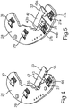
- the flux conductor 33 is shown according to an embodiment, wherein the flux conductor 32 is constructed correspondingly identical.
- the flux conductor 33 has a plate-shaped and substantially rectangular receiving region 42, in which the passage openings 35 are formed. At a right angle is from the receiving portion 42 from a web 43 from which in turn also at a right angle a radial tab 44 protrudes, which extends parallel to the receiving region 42.
- the tab 44 is significantly smaller than the receiving area 42 and also plate-shaped. It is arranged offset in the axial direction of the reception area 42.
- the tab 44 is arranged in mutual axial overlap with the magnetic sensor 27 of the torque sensor device and thereby at a very small axial distance from the magnetic sensor 27.
- the first flux guide 32 has a corresponding tab 44 which extends axially into a recess formed in the circuit board 28 below the magnetic sensor 27 to ensure reliable transmission of the magnetic flux.
- the tab 44 of the first flux guide 32 is arranged in axial overlap with the magnetic sensor 27, so that the magnetic sensor 27 is arranged axially between the two tabs 44.
- the single magnetic sensor 27 can be designed as a simple sensor or as a dual sensor.
- a total of two sensor elements are integrated in a single SMD component, which are designed for separate detection of the magnetic flux and provide sensor signals separately from one another.
- the flux conductor 33 has a total of two tabs 44a, 44b, which are connected via respective webs 43a, 43b to the receiving region 42.
- the passage openings 35 are now formed between the webs 43a, 43b.
- the two tabs 44a, 44b lie in a common plane and extend parallel to the receiving region 42.
- Each tab 44a, 44b is arranged in axial overlap with a separate magnetic sensor 27a, 27b, which are both attached to the circuit board 28 as SMD components ,
- the magnetic sensors 27a, 27b may be simple or dual sensors.
- Fig. 5 also has the first flux guide 32 corresponding to two separate tabs, which in axial overlap with the respective magnetic sensors 27a, 27b are arranged and in this case lie for example in respective recesses in the printed circuit board 28.
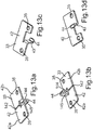
- FIGS. 13a to 13d Two other examples of flux guides 33 are shown in FIGS FIGS. 13a to 13d shown.
- the flux conductor 33 according to Fig. 13a and 13b also has a tab 44, which, however, is substantially axially oriented and points in the axial direction.
- This tab 44 is formed by the fact that approximately in the middle of the receiving area 42, a slot 142 is formed, which divides the receiving area 42 into two parts 42a, 42b.
- An axial extension 144, 145 projects perpendicularly from each part 42a, 42b, whereby the extensions 144, 145 are brought together at their ends and thus form the axial lug 44 overall.
- the tip of this tab 44 is then in axial overlap with the magnetic sensor 27th
- FIG. 13c and 13d Another example is in the Figures 13c and 13d shown.
- This flux conductor 33 essentially corresponds to that according to FIG Fig. 4 , wherein the tab 44 now extends in the tangential direction. It is connected via the web 43 to the reception area 42. Only the orientation of the web 43 and thus the tab 44 thus differs from the embodiment according to Fig. 4 ,
- the housing 12 pins or pins 45, which can be received in corresponding through holes 46 of the lid 31.
- the attachment of the lid 31 on the housing 12 is then carried out by forming the pins 45 to rivet heads.
- the device 1 is in the assembled state in Fig. 6 shown.
- the second axial region 4 of the holder 2 which projects axially out of the housing 12.
- the sleeve 47 adjoins this region 4 in the axial direction, via which the holder 2 is connected to the associated shaft part.
- the stator 17 is shown with its edge element 19, which is attached via the pins 22 on the holder 2.
- the flux conductors 32, 33 and the circuit board 28 with the components 27, 29, 30 and the gear 37 Inside the housing 12 and thus not shown are the flux conductors 32, 33 and the circuit board 28 with the components 27, 29, 30 and the gear 37.
- the housing 12 is fastened together with the lid 31 on a vehicle part and the device 1 is electrically connected via the plug 41.
- the housing 12 is thus fixed relative to the steering shaft.
- the holder 2 with the stator parts 10, 17 can be rotated relative to the housing 12 and to the flux conductors 32, 33, namely together with the steering shaft.
- the respective tooth elements 20, 21 of the mutual stator parts 10, 17 can be seen.
- These tooth elements 20, 21 can be arranged, for example, in depressions, which are formed on the inner periphery of the first axial portion 3 of the holder 2.
- the receptacle 36 for the transmission 37 is formed at the same axial height as the sleeve 13 and arranged radially offset from the sleeve 13.
- the printed circuit board 28 is located axially between the respective edge elements 18, 19 of the stator parts 10, 17.
- the components 27, 29, 30 may be arranged centrally in the axial direction between the edge elements 18, 19.
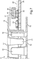
- Fig. 7 illustrates a partial sectional view through the printed circuit board 28 and the magnetic field detector 30.
- the tooth elements 20 engage between the tooth elements 21.
- a center plane extending exactly axially between the edge elements 17, 18 is designated 48, which represents a plane of symmetry of the stator 11 .
- the components 27, 29, 30 are in this embodiment axially centered in the plane of symmetry or center plane 48.
- the gears 38, 39, 40 axially offset with respect to the median plane 48 and thus arranged asymmetrically.
- This is in Fig. 7 shown by the gear 38 with its permanent magnet (49).
- the two flux conductors 32, 33 are arranged mirror-symmetrically with respect to the center plane 48.
- the respective receiving regions 42 of the flux conductors 32, 33 can either lie axially within the stator 11 and thus axially between the edge elements 18, 19 or else axially outside the stator 11.
- the permanent magnets 49 of the gears 38, 40 can be surface-magnetized such that the magnetic field at the axial height of the two edge elements 18, 19 is the same size and thus cancel each other. Thus, a crosstalk between the two sensor types is prevented.
- the gears 38, 39, 40 can optionally be brought a little further outward in the radial direction in order to further reduce the crosstalk.
- the components 27, 29, 30 may be arranged eccentrically in the axial direction between the edge elements 18, 19, and the permanent magnets 49 of the gears 38, 40 may be located axially in the middle between the edge elements 38, 40. Then corresponds to the axial distance between the Permanent magnet and the edge element 38, the axial distance between the permanent magnet and the other edge element 40.
- Such an arrangement of the circuit board 28 and the transmission 37 is in the FIGS. 8 and 9 shown. While in Fig. 8 a sectional view through the printed circuit board 28 is shown at the location of the magnetic detector 30 shows Fig. 9 a sectional view through the circuit board 28 at the height of the magnetic sensor 27. The stator 11 is shown in perspective. How out Fig. 8 The permanent magnet 49 lies exactly in the center plane 48. Even in the case of a conventional magnet 49, which is not specially surface-magnetized, essentially the same magnetic field results at the respective edge elements 18, 19.
- the two flux conductors 32, 33 are arranged asymmetrically with respect to the central axis 48.
- the receiving region 42 of one of the flux conductors 32, 33 lies axially outside the stator 11 or axially offset from the stator 11, while the receiving region 42 of the other flux conductor 32, 33 lies axially within the stator 11.
- the continuous recess 50 in the circuit board 28 below the magnetic sensor 27 can be seen.
- the tab 44 of the flux guide 32 is arranged, which is arranged on the back of the printed circuit board 28.
- the magnetic sensor 27 is thus very dense sandwiched by the tabs 44 of the flux conductors 32, 33 and lies axially between the two tabs 44th
- a flex circuit board 28 is used, ie a printed circuit board 28 in the form of a thin film whose thickness is preferably less than 0.2 mm.
- a recess under the magnetic sensor 27 can be omitted because the magnetic flux can be transmitted through the film.
- the two flux conductors 32, 33 are arranged mirror-symmetrically with respect to the center plane 48.
- the respective receiving regions 42 of the flux conductors 32, 33 are here axially arranged within the stator 11 and thus axially between the edge elements 18, 19, so that the two flux conductors 32, 33 are completely axially wiping the edge elements 18, 19.
- FIG. 11 Another example is in Fig. 11 shown.
- This arrangement essentially corresponds to the according Fig. 9 , but with the difference that the flux conductors 32, 33 are formed asymmetrically and both flux conductors 32, 33 axially within the stator 11 and thus axially between the edge elements 18, 19 are arranged.
- This is made possible by the fact that the flux conductor 32 is formed with a shorter web 43 than the flux conductor 33.
- the axial height is further reduced.
- the circuit board 28 extends in the axial direction and is thus arranged parallel to the axial axis.
- the magnetic sensor 27 extends along the axial direction, so that a mutual overlap between the magnetic sensor 27 and the tabs 44 is given in the radial direction.
- the tabs 44 now extend in the axial direction and thus parallel to the printed circuit board 28.
- they can protrude directly from the respective receiving region 42 perpendicularly in the direction of the respective other flux conductor 32, 33.
- Both flux conductors 32, 33 are arranged axially within the stator 11 and thus axially between the edge elements 18, 19, but are formed asymmetrically.
- a recess 50 is provided in the circuit board 28, which now extends to the edge of the circuit board 28 and thus forms a recess.
- the receiving region 42 of the flux conductor 32 extends axially into it in order to be able to arrange the tab 44 of this flux conductor 32 on the rear side of the magnetic sensor 27.
- the example according to the Figures 12a and 12b proves to be particularly advantageous in a pure torque sensor when the steering angle sensor device is dispensed with. Then can be advantageous by Geometrierestriktionen the steering housing, an axial arrangement of the circuit board.
- two differently shaped flux conductors 32, 33 are used here in order to reach the magnetic field sensor 27 both from the radial outer side and from the radial inner side.
- a thin flex circuit board can be used instead of a standard circuit board 28 with recess 50.
- a metallic shield 51 in particular a sheet-like shielding can be provided.
- a shield 51 is arranged on the back side of the printed circuit board 28 and extends parallel to the center plane 48.
- a shield 51 may also be provided on the other side of the printed circuit board 28 in addition or alternatively.
- the shield 51 may also be formed as a metallization of the printed circuit board 28 directly on its rear side or front side.
- respective shielding plates can be provided on both axial sides of the gears 38, 39, 40, which prevent the crosstalk between the two sensor types via the stator 11.
- the permanent magnets 49 can be magnetized diametrically.
Description
Die Erfindung betrifft eine Vorrichtung für ein Kraftfahrzeug, mit einer Drehmomentsensoreinrichtung zur Erfassung eines auf eine Lenkwelle des Kraftfahrzeugs aufgebrachten Drehmoments, und mit einer Lenkwinkelsensoreinrichtung zur Erfassung eines aktuellen Lenkwinkels der Lenkwelle, wobei die Drehmomentsensoreinrichtung einen magnetischen Stator aufweist, der zum Leiten von magnetischem Fluss von einem Magneten hin zu zumindest einem Flussleiter und hierdurch zu zumindest einem Magnetsensor der Drehmomentsensoreinrichtung ausgebildet ist und zwei in axialer Richtung versetzt zueinander angeordnete Statorteile aufweist, welche jeweils ein sich in radialer Richtung erstreckendes, ringförmiges Randelement aufweisen, und wobei die Lenkwinkelsensoreinrichtung zumindest ein Drehübertragungselement mit einem Permanentmagneten und einen Magnetfelddetektor zur Erfassung einer Drehbewegung des Drehübertragungselements aufweist,wobei das zumindest eine Drehübertragungselement mit dem Permanentmagneten in axialer Richtung zwischen den Randelementen angeordnet ist und wobei die Lenkwinkelsensoreinrichtung einen Rotor mit einer Zahnstruktur aufweist und das Drehübertragungselement als Zahnrad ausgebildet ist, das in Eingriff mit der Zahnstruktur des Rotors bringbar ist und mittels welchem eine Drehbewegung des Rotors in eine Drehbewegung des Permanentmagneten übertragbar ist, wobei die Lenkwinkelsensoreinrichtung ein Zahnradgetriebe mit wenigstens zwei Zahnrädern umfasst, deren Zähne in jene des Rotors greifen und auf diese Weise mit dem Rotor gekoppelt sind, wobei in einem Zahnrad ein Permanentmagnet angeordnet ist und die Rotationsachse des Zahnrads parallel zur Drehachse der Lenkwelle ist. Drehmomentsensoreinrichtungen zur Erfassung eines auf eine Lenkwelle eines Kraftfahrzeugs aufgebrachten Drehmoments sind bereits Stand der Technik. Solche Drehmomentsensoreinrichtungen können beispielsweise bei elektrischen Lenksystemen eingesetzt werden. Eine Drehmomentsensoreinrichtung ist zum Beispiel aus dem Dokument
Eine solche Drehmomentsensoreinrichtung ist außerdem aus dem Dokument
Außerdem sind aus dem Stand der Technik auch Lenkwinkelsensoreinrichtungen bekannt, welche zur Erfassung des aktuellen Lenkwinkels der Lenkwelle dienen. Eine solche Einrichtung ist zum Beispiel aus dem Dokument
Das Interesse richtet sich vorliegend auf Vorrichtungen, bei denen die Drehmomentsensoreinrichtung einerseits sowie die Lenkwinkelsensoreinrichtung andererseits integral als eine gemeinsame Baueinheit ausgebildet sind. Eine solche Vorrichtung mit einem Drehmomentsensor und einem Drehwinkelsensor ist beispielsweise aus dem Dokument
Es ist Aufgabe der Erfindung, eine Lösung aufzuzeigen, wie bei einer Vorrichtung der eingangs genannten Gattung die axiale Bauhöhe im Vergleich zum Stand der Technik reduziert werden kann.It is an object of the invention to provide a solution, as in a device of the type mentioned, the axial height compared to the prior art can be reduced.
Diese Aufgabe wird erfindungsgemäß durch eine Vorrichtung mit den Merkmalen gemäß dem unabhängigen Patentanspruch 1 gelöst. Vorteilhafte Ausführungen der Erfindung sind Gegenstand der abhängigen Patentansprüche, der Beschreibung und der Figuren.This object is achieved by a device having the features according to
Eine erfindungsgemäße Vorrichtung für ein Kraftfahrzeug umfasst eine Drehmomentsensoreinrichtung, welche zur Erfassung eines auf eine Lenkwelle des Kraftfahrzeugs aufgebrachten Drehmoments ausgebildet ist, sowie eine Lenkwinkelsensoreinrichtung, welche zur Erfassung des aktuellen Lenkwinkels der Lenkwelle ausgebildet ist. Die Drehmomentsensoreinrichtung weist einen magnetischen Stator auf, der zum Leiten von magnetischem Fluss von einem Magneten hin zu zumindest einem Flussleiter und hierdurch zu zumindest einem Magnetsensor ausgebildet ist. Der Stator umfasst zwei in axialer Richtung versetzt zueinander angeordnete Statorteile, welche jeweils ein sich in radialer Richtung erstreckendes, ringförmiges Randelement aufweisen. Die Lenkwinkelsensoreinrichtung umfasst zumindest ein Drehübertragungselement (zum Beispiel ein Zahnrad) mit einem Permanentmagneten und einen Magnetfelddetektor zur Erfassung einer Drehbewegung des Drehübertragungselements. Auf das Drehübertragungselement kann eine Drehbewegung der Lenkwelle übertragen werden. Das zumindest eine Drehübertragungselement mit dem Permanentmagneten sind in axialer Richtung zwischen den Randelementen angeordnet.An inventive device for a motor vehicle comprises a torque sensor device, which is designed to detect a torque applied to a steering shaft of the motor vehicle, and a steering angle sensor device, which is designed to detect the current steering angle of the steering shaft. The torque sensor device has a magnetic stator for directing magnetic flux from a magnet at least one flux guide and thereby formed to at least one magnetic sensor. The stator comprises two offset in the axial direction of each other arranged stator parts, each having a radially extending, annular edge element. The steering angle sensor device includes at least one rotation transmitting member (for example, a gearwheel) having a permanent magnet and a magnetic field detector for detecting rotational movement of the rotation transmitting member. On the rotation transmission element, a rotational movement of the steering shaft can be transmitted. The at least one rotation transmission element with the permanent magnet are arranged in the axial direction between the edge elements.
Erfindungsgemäß wird somit vorgeschlagen, das wesentliche Bauteil der Lenkwinkelsensoreinrichtung, nämlich das zumindest ein Drehübertragungselement mit seinem Permanentmagneten, nicht axial außerhalb des Stators, sondern in axialer Richtung zwischen den beiden Statorteilen bzw. zwischen den jeweiligen Randelementen anzuordnen. Bei gleichbleibendem axialen Abstand zwischen den Statorteilen reduziert sich somit die axiale Bauhöhe bzw. die axiale Ausdehnung der gesamten Vorrichtung im Vergleich zum Stand der Technik bzw. im Vergleich zu Ausführungsformen, bei denen das Drehübertragungselement und mit seinem Permanentmagneten axial zum Stator versetzt angeordnet ist. Es wird somit insgesamt eine in axialer Richtung sehr kompakte und bauraumsparende integrierte Vorrichtung geschaffen, welche sowohl zur Erfassung des Drehmoments als auch zur Erfassung des Lenkwinkels ausgebildet ist.According to the invention, it is thus proposed to arrange the essential component of the steering angle sensor device, namely the at least one rotational transmission element with its permanent magnet, not axially outside the stator but in the axial direction between the two stator parts or between the respective edge elements. At constant axial distance between the stator thus reduces the axial height or the axial extent of the entire device compared to the prior art or compared to embodiments in which the rotation transmission element and its permanent magnet is arranged axially offset from the stator. It is thus a total in the axial direction very compact and space-saving integrated device created, which is designed both for detecting the torque and for detecting the steering angle.
Das zumindest eine Drehübertragungselement steht bevorzugt in gegenseitiger Wirkverbindung mit einem Rotor, der mit einem der Wellenteile verbunden wird. Über den Rotor kann dann die Drehbewegung der Lenkwelle auf das in seinem Durchmesser kleinere Drehübertragungselement übertragen werden, und die Drehbewegung des Drehübertragungselements kann mit dem Magnetfelddetektor erfasst und daraus der Lenkwinkel ermittelt werden. Das zumindest eine Drehübertragungselement ist bevorzugt als Zahnrad mit einer umlaufenden Zahnstruktur ausgebildet, welches in Eingriff mit einem Rotor steht, der mit der Lenkwelle drehfest verbunden ist und eine umlaufende Zahnstruktur aufweist. Der Rotor kann an einem Halter angeordnet sein, an welchem auch der magnetische Stator angebracht ist.The at least one rotational transmission element is preferably in mutual operative connection with a rotor which is connected to one of the shaft parts. The rotary motion of the steering shaft can then be transmitted to the smaller rotational transmission element in its diameter via the rotor, and the rotational movement of the rotational transmission element can be detected by the magnetic field detector and the steering angle can be determined therefrom. The at least one rotation transmission element is preferably formed as a gear with a circumferential tooth structure, which is in engagement with a rotor which is rotatably connected to the steering shaft and has a circumferential tooth structure. The rotor may be arranged on a holder on which also the magnetic stator is mounted.
Der genannte Magnet, von welchem der magnetische Fluss über den Stator bis hin zum Flussleiter und hierdurch zum Magnetsensor geleitet wird, kann beispielsweise mit einem ersten Wellenteil der Lenkwelle verbunden werden. Der magnetische Stator hingegen kann an dem genannten Halter angeordnet und mit diesem drehfest verbunden werden, der mit einem zweiten Wellenteil der Lenkwelle verbunden werden kann. Die beiden Wellenteile können insbesondere über einen Torsionsstab miteinander gekoppelt sein. Optional kann für den Halter ein Gleitstück eingesetzt werden, welches zum Tragen des zumindest einen Flussleiters ausgebildet ist, wobei dann der Halter mit dem Stator relativ zum Gleitstück und somit relativ zum Flussleiter drehbar angeordnet ist.The said magnet, from which the magnetic flux is conducted via the stator as far as the flux guide and thereby to the magnetic sensor, can be connected, for example, to a first shaft part of the steering shaft. The magnetic stator, on the other hand can be arranged on the said holder and rotatably connected thereto, which can be connected to a second shaft portion of the steering shaft. The two shaft parts can be coupled to each other in particular via a torsion bar. Optionally, a slider can be used for the holder, which is designed to support the at least one flux guide, in which case the holder is rotatably arranged with the stator relative to the slider and thus relative to the flux guide.
In einer Ausführungsform ist vorgesehen, dass das zumindest ein Drehübertragungselement mit seinem Permanentmagneten zumindest bereichsweise in gegenseitiger axialer Überlappung mit den Randelementen der Statorteile angeordnet ist. Dies bedeutet, dass eine Projektion des Drehübertragungselements in axialer Richtung auf die beiden Randelemente existiert. Durch eine solche Anordnung des zumindest einen Drehübertragungselements wird die Ausdehnung der Vorrichtung auch in radialer Richtung reduziert.In one embodiment, it is provided that the at least one rotation transmission element is arranged with its permanent magnet at least partially in mutual axial overlap with the edge elements of the stator. This means that a projection of the rotation transmission element in the axial direction exists on the two edge elements. By such an arrangement of the at least one rotation transmission element, the expansion of the device is also reduced in the radial direction.
Ergänzend oder alternativ kann zumindest ein Drehübertragungselement mit seinem zugeordneten Permanentmagneten in radialer Richtung versetzt zu den Randelementen angeordnet sein. Dies wiederum bedeutet, dass keine axiale Projektion des Drehübertragungselements auf die beiden Randelemente der Statorteile existiert. Diese Ausführungsform hat den Vorteil, dass ein Übersprechen zwischen dem Permanentmagneten und dem Magnetsensor der Drehmomentsensoreinrichtung über den magnetischen Stator verhindert werden kann. Somit werden auch Fehler bei der Erfassung des Drehmoments verhindert.Additionally or alternatively, at least one rotational transmission element can be arranged with its associated permanent magnet offset in the radial direction to the edge elements. This in turn means that there is no axial projection of the rotation transmission element on the two edge elements of the stator. This embodiment has the advantage that crosstalk between the permanent magnet and the magnetic sensor of the torque sensor device via the magnetic stator can be prevented. Thus, errors in the detection of the torque can be prevented.
Die axiale Bauhöhe wird weiterhin dann reduziert, wenn der Magnetfelddetektor an einer Leiterplatte angeordnet ist, welche axial zwischen den beiden Randelementen bzw. axial zwischen den Statorteilen und insbesondere auch parallel zu den Randelementen angeordnet ist.The axial height is further reduced when the magnetic field detector is arranged on a printed circuit board, which is arranged axially between the two edge elements or axially between the stator and in particular also parallel to the edge elements.
Also weisen die beiden Statorteile jeweils ein sich in radialer Richtung erstreckendes bzw. radial nach außen hin weisendes, ringförmiges und insbesondere flanschartiges sowie einen axialen Rand des jeweiligen Statorteils bildendes Randelement auf. Diese Randelemente stehen somit senkrecht zur Drehachse der Lenkwelle bzw. der Vorrichtung und parallel zueinander. Von den jeweiligen Randelementen kann jeweils eine Vielzahl von in Umfangsrichtung verteilt angeordneten Zahnelementen in axialer Richtung abstehen. Die Zahnelemente des einen Statorteils sind dann mit den Zahnelementen des anderen Statorteils abwechselnd in Umfangsrichtung verteilt angeordnet, sodass die Zahnelemente des einen Statorteils sich in jeweilige Zwischenräume zwischen den Zahnelementen des anderen Statorteils axial hinein erstrecken. Die flanschartigen Randelemente überlappen sich dabei vorzugsweise gegenseitig in axialer Richtung, und die jeweiligen Zahnelemente zeigen bevorzugt axial in entgegengesetzte Richtungen. Die ringförmigen Randelemente dienen dabei zum Übertragen des magnetischen Flusses an den jeweiligen Flussleiter. Ein plattenförmiger Empfangsbereich des Flussleiters wird hierzu bevorzugt in einem sehr geringen Abstand zum flanschartigen Randelement des jeweiligen Statorteils angeordnet. Die Zahnelemente hingegen dienen zum Empfangen des magnetischen Flusses von dem Magneten, der an einem der Wellenteile angebracht ist.Thus, the two stator parts each have a radially extending or radially outwardly facing, annular and in particular flange-like and an axial edge of the respective stator part forming edge element. These edge elements are thus perpendicular to the axis of rotation of the steering shaft and the device and parallel to each other. Of the respective edge elements can each protrude a plurality of circumferentially distributed tooth elements arranged in the axial direction. The tooth elements of a stator are then arranged alternately distributed with the tooth elements of the other stator in the circumferential direction, so that the Tooth elements of a stator part extending axially into respective spaces between the tooth elements of the other stator. The flange-like edge elements preferably overlap one another in the axial direction, and the respective tooth elements preferably point axially in opposite directions. The annular edge elements serve to transmit the magnetic flux to the respective flux guide. For this purpose, a plate-shaped receiving region of the flux guide is preferably arranged at a very small distance from the flange-like edge element of the respective stator part. The tooth elements, on the other hand, serve to receive the magnetic flux from the magnet, which is attached to one of the shaft parts.
In einer Ausführungsform ist der Permanentmagnet des Drehübertragungselements in axialer Richtung außermittig zwischen den beiden Randelementen angeordnet. Bevorzugt ist dabei der zumindest eine Magnetsensor der Drehmomentsensoreinrichtung axial mittig zwischen den beiden Statorteilen bzw. den jeweiligen Randelementen angeordnet. Dies bedeutet, dass der zumindest eine Magnetsensor im gleichen axialen Abstand von den beiden Randelementen liegt. Der Permanentmagnet des Drehübertragungselements ist bei dieser Ausführungsform vorzugsweise dazu ausgebildet bzw. derart oberflächenmagnetisiert, dass er an den jeweiligen Randelementen der Statorteile ein Magnetfeld mit gleicher Feldstärke bereitstellt. Das Magnetfeld ist somit auf der jeweiligen axialen Höhe der beiden Randelemente gleich groß, sodass sich diese Magnetfelder des Permanentmagneten an den beiderseitigen Randelementen gegenseitig aufheben. Somit wird eine Beeinflussung des magnetischen Flusses verhindert, der über den Stator hin zum Magnetsensor geleitet wird. Fehler bei der Erfassung des Drehmoments können somit verhindert werden.In one embodiment, the permanent magnet of the rotation transmission element is arranged eccentrically in the axial direction between the two edge elements. In this case, the at least one magnetic sensor of the torque sensor device is preferably arranged axially in the middle between the two stator parts or the respective edge elements. This means that the at least one magnetic sensor is located at the same axial distance from the two edge elements. The permanent magnet of the rotation transmission element is preferably formed in this embodiment or surface magnetized such that it provides a magnetic field with the same field strength at the respective edge elements of the stator. The magnetic field is thus equal to the respective axial height of the two edge elements, so that cancel these magnetic fields of the permanent magnet to the mutual edge elements mutually. Thus, an influence of the magnetic flux is prevented, which is passed over the stator to the magnetic sensor. Errors in the detection of the torque can thus be prevented.
Gemäß einer alternativen Ausführungsform kann der Magnet des Drehübertragungselements axial mittig zwischen den beiden Statorteilen bzw. den jeweiligen Randelementen angeordnet sein, sodass der Magnetsensor der Drehmomentsensoreinrichtung und der Magnetfelddetektor der Lenkwinkelsensoreinrichtung axial außermittig liegen. Bei dieser Ausführungsform werden die beiden Flussleiter bevorzugt asymmetrisch bezüglich einer Symmetrieebene bzw. Mittelebene zwischen den beiderseitigen Randelementen der Statorteile angeordnet. Der eine Flussleiter kann vollständig axial innerhalb des Stators und somit axial zwischen den Randelementen liegen, während der andere Flussleiter zumindest mit seinem Empfangsbereich axial außerhalb des Stators bzw. axial versetzt dazu angeordnet sein kann. Eine solche Anordnung des Permanentmagneten axial in der Mitte zwischen den Randelementen hat den Vorteil, dass die Feldstärke des Magnetfeldes an den beiden Randelementen auch bei einem "normalen" Permanentmagneten ohne eine spezielle Oberflächenmagnetisierung gleich ist, sodass kein Übersprechen zwischen den beiden Sensorarten stattfindet.According to an alternative embodiment, the magnet of the rotation transmission element can be arranged axially in the middle between the two stator parts or the respective edge elements, so that the magnetic sensor of the torque sensor device and the magnetic field detector of the steering angle sensor device lie axially off-center. In this embodiment, the two flux conductors are preferably arranged asymmetrically with respect to a plane of symmetry or center plane between the mutual edge elements of the stator parts. The one flux conductor can lie completely axially within the stator and thus axially between the edge elements, while the other flux conductor can be arranged at least with its reception region axially outside the stator or axially offset therefrom. Such an arrangement of the permanent magnet axially in the middle between the Edge elements has the advantage that the field strength of the magnetic field at the two edge elements is the same even with a "normal" permanent magnet without a special surface magnetization, so that no crosstalk between the two sensor types takes place.
Im Allgemeinen können die beiden Flussleiter gleiche Bauteile sein oder sie können auch unterschiedlich ausgebildet sein.In general, the two flux conductors can be the same components or they can also be designed differently.
Optional kann auch eine Abschirmung für Magnetfelder axial zwischen dem Permanentmagneten des Drehübertragungselements einerseits und zumindest einem der Randelemente andererseits angeordnet sein. Eine solche Abschirmung kann insbesondere in Form eines Abschirmungsbleches bereitgestellt werden, das sich parallel zur Leiterplatte erstreckt. Die Abschirmung hat den Vorteil, dass ein Übersprechen zwischen den beiden Sensorteilen über den Stator wirkungsvoll minimiert werden kann. Sie kann gegebenenfalls auch durch eine Metallisierung der Leiterplatte selbst gebildet sein oder ein zur Leiterplatte separates Bauteil darstellen.Optionally, a shield for magnetic fields can also be arranged axially between the permanent magnet of the rotation transmission element on the one hand and at least one of the edge elements on the other hand. Such a shield may in particular be provided in the form of a shielding plate which extends parallel to the printed circuit board. The shield has the advantage that crosstalk between the two sensor parts via the stator can be effectively minimized. If appropriate, it can also be formed by a metallization of the printed circuit board itself or can be a component that is separate from the printed circuit board.
Wie bereits ausgeführt, umfasst die Lenkwinkelsensoreinrichtung bevorzugt einen Rotor mit einer Zahnstruktur. Das Drehübertragungselement kann als Zahnrad ausgebildet sein, das in Eingriff mit der Zahnstruktur des Rotors bringbar ist und mittels welchem eine Drehbewegung des Rotors und somit der Lenkwelle in eine Drehbewegung des Permanentmagneten übertragen wird. Vorzugsweise ist der Rotor mit seiner umlaufenden Zahnstruktur direkt an den genannten Halter angespritzt, an welchem der Stator angeordnet ist und welcher mit einem der Wellenteile der Lenkwelle verbunden wird. Dadurch entfällt ein zusätzliches Zahnrad als eigenständiges Teil, wie auch der dazugehörige Fügeprozess des Rotors auf den Halter. Durch diese einstückige Ausgestaltung des Rotors mit dem Halter ergibt sich außerdem ein verbesserter Rundlauf der Zahnelemente.As already stated, the steering angle sensor device preferably comprises a rotor with a tooth structure. The rotation transmission member may be formed as a gear which is engageable with the tooth structure of the rotor and by means of which a rotational movement of the rotor and thus the steering shaft is transmitted in a rotational movement of the permanent magnet. Preferably, the rotor is molded with its circumferential tooth structure directly to the said holder, on which the stator is arranged and which is connected to one of the shaft parts of the steering shaft. This eliminates an additional gear as an independent part, as well as the associated joining process of the rotor on the holder. This one-piece design of the rotor with the holder also results in an improved concentricity of the tooth elements.
In einer bevorzugten Ausführungsform ist der zumindest eine Magnetsensor der Drehmomentsensoreinrichtung als SMD-Bauelement (Surface-Mounted-Device) ausgebildet, welches an einer Leiterplatte angeordnet ist, nämlich insbesondere einer für die Drehmomentsensoreinrichtung und die Lenkwinkeleinrichtung gemeinsamen Leiterplatte, an welcher auch der Magnetfelddetektor der Lenkwinkelsensoreinrichtung angebracht ist. Der zumindest eine Flussleiter weist dabei bevorzugt eine Lasche auf, die in gegenseitiger Überlappung mit dem Magnetsensor angeordnet ist. Während im Stand der Technik aufgrund der Ausgestaltung des Flussleiters der Magnetsensor als THT-Bauelement (Throuh-Hole-Technology) ausgebildet werden muss, wird bei dieser Ausführungsform vorgeschlagen, den Magnetsensor als SMD-Bauelement auszubilden und den Flussleiter derart auszugestalten, dass er eine, insbesondere sich in radialer Richtung erstreckende, Lasche aufweist, die in gegenseitiger Überdeckung mit dem Magnetsensor angeordnet ist. Dadurch entfällt die Bestückung und Lötung von bedrahteten Bauelementen mit den damit verbundenen Nachteilen. Alle Bauelemente können als SMD-Bauelemente auf der Leiterplatte in einem gemeinsamen Fertigungsschritt montiert werden, sodass sich insgesamt der Fertigungsaufwand im Vergleich zum Stand der Technik deutlich reduziert. Weil SMD-Bauelemente auch besonders flach ausgeführt werden können, kann die Größe der Vorrichtung in Richtung senkrecht zur Leiterplatte, insbesondere in axialer Richtung, weiterhin reduziert werden. Insbesondere ergibt sich eine deutliche Reduzierung der axialen Bauhöhe, wenn die Leiterplatte senkrecht zur axialen Richtung angeordnet ist bzw. in einer radialen Ebene liegt. Bevorzugt ist die Leiterplatte dabei axial zwischen den beiden Randelementen der Statorteile angeordnet.In a preferred embodiment, the at least one magnetic sensor of the torque sensor device is designed as an SMD component (surface-mounted device), which is arranged on a printed circuit board, namely in particular a printed circuit board common to the torque sensor device and the steering angle device, to which the magnetic field detector of the steering angle sensor device is also attached is appropriate. The at least one flux guide preferably has a tab which is arranged in mutual overlap with the magnetic sensor. While in the prior art due to the design of the flux guide of the magnetic sensor as a THT device (Throuh-hole technology) must be formed is proposed in this embodiment, form the magnetic sensor as an SMD component and the flux guide to design such that it has a, in particular extending in the radial direction, tab in mutual overlap with the Magnetic sensor is arranged. This eliminates the assembly and soldering of wired components with the associated disadvantages. All components can be mounted as SMD components on the circuit board in a common manufacturing step, so that overall the manufacturing cost significantly reduced compared to the prior art. Because SMD components can also be made particularly flat, the size of the device in the direction perpendicular to the printed circuit board, in particular in the axial direction, can be further reduced. In particular, there is a significant reduction in the axial height when the circuit board is arranged perpendicular to the axial direction or lies in a radial plane. Preferably, the circuit board is arranged axially between the two edge elements of the stator.
Um die axiale Bauhöhe weiterhin zu reduzieren, ist in einer Ausführungsform vorgesehen, dass die Lasche des Flussleiters eine axiale oder eine radiale bzw. in radialer Richtung weisende Lasche ist, die in gegenseitiger axialer Überdeckung mit dem Magnetsensor angeordnet ist.In order to further reduce the axial height, it is provided in one embodiment that the tab of the flux guide is an axial or a radial or pointing in the radial direction tab, which is arranged in mutual axial overlap with the magnetic sensor.
Die Lasche kann also eine radiale Lasche sein, die in radialer Richtung zeigt. Alternativ kann jedoch auch vorgesehen sein, dass die Lasche im Wesentlichen in axialer Richtung weist und somit axial orientiert ist, ohne dass sie einen speziellen radialen Abschnitt aufweist. Auch hier ist dann eine gegenseitige Überlappung zwischen der Lasche und dem Magnetsensor gegeben, nämlich insbesondere in axialer Richtung oder alternativ in radialer Richtung, abhängig von der Orientierung der Leiterplatte.The tab can therefore be a radial tab which points in the radial direction. Alternatively, however, it may also be provided that the tab is directed substantially in the axial direction and thus oriented axially, without having a special radial section. Here, too, a mutual overlap between the tab and the magnetic sensor is then given, namely in particular in the axial direction or alternatively in the radial direction, depending on the orientation of the circuit board.
Bevorzugt weist der zumindest eine Flussleiter einen in gegenseitiger axialer Überlappung mit dem Stator angeordneten, plattenförmigen Empfangsbereich zum Empfangen des magnetischen Flusses von dem Stator auf. Dann kann die sich parallel zum Empfangsbereich erstreckende Lasche in axialer Richtung versetzt zum Empfangsbereich angeordnet sein. Dies bedeutet, dass die radiale Lasche des Flussleiters über einen Steg bzw. ein Brückenelement mit dem Empfangsbereich verbunden ist, wobei der Steg gewinkelt, insbesondere senkrecht, sowohl zum Empfangsbereich als auch zur Lasche angeordnet ist. Der Flussleiter ist dabei vorzugsweise insgesamt einstückig ausgebildet, sodass der Empfangsbereich einerseits sowie der Steg und die radiale Lasche andererseits einstückig miteinander ausgebildet sind. Dadurch, dass die radiale Lasche in axialer Richtung versetzt zum Empfangsbereich des Flussleiters angeordnet ist, kann einerseits der Empfangsbereich in einem sehr geringen Abstand zum Stator und andererseits die Lasche in einem sehr geringen Abstand zum Magnetsensor angeordnet werden, sodass eine zuverlässige Übertragung des magnetischen Flusses vom Stator hin zum Magnetsensor gewährleistet ist.Preferably, the at least one flux guide has a plate-shaped receiving region arranged in mutual axial overlap with the stator for receiving the magnetic flux from the stator. Then, the flap extending parallel to the receiving region can be arranged offset in the axial direction to the receiving region. This means that the radial lug of the flux guide is connected via a web or a bridge element to the receiving region, wherein the web is angled, in particular perpendicular, arranged both to the receiving region and to the tab. The flux conductor is preferably formed integrally in one piece, so that the reception area on the one hand and the web and the radial tab on the other hand are integrally formed with each other. The fact that the radial tab is arranged offset in the axial direction to the receiving region of the flux guide, on the one hand the receiving area can be arranged at a very small distance from the stator and on the other hand, the tab at a very small distance from the magnetic sensor, so that a reliable transmission of the magnetic flux from Stator is guaranteed to the magnetic sensor.
Der zumindest eine Flussleiter kann - ähnlich wie der Stator - aus einem magnetischen, z. B. weichmagnetischen, Material gebildet sein.The at least one flux guide can - similar to the stator - from a magnetic, z. B. soft magnetic, material may be formed.
Die Drehmomentsensoreinrichtung kann auch zwei Flussleiter mit jeweils zumindest einer genannten Lasche aufweisen, die auf einander gegenüberliegenden Seiten der Leiterplatte angeordnet sind. Die jeweiligen Laschen können in gegenseitiger, insbesondere axialer, Überdeckung mit dem Magnetsensor angeordnet sein. Somit ist der Magnetsensor quasi als Sandwich-Element zwischen der Lasche des einen Flussleiters einerseits und der Lasche des anderen Flussleiters andererseits angeordnet und überlappt die beiden Laschen insbesondere in axialer Richtung. Somit kann die Übertragung des magnetischen Flusses über die beiden separaten Statorteile sowie über die jeweiligen Flussleiter hin zu dem Magnetsensor ermöglich werden, sodass auch eine zuverlässige Erfassung des Drehmoments gewährleistet ist.The torque sensor device may also have two flux guides, each with at least one said tab, which are arranged on opposite sides of the circuit board. The respective tabs can be arranged in mutual, in particular axial, overlap with the magnetic sensor. Thus, the magnetic sensor is arranged quasi as a sandwich element between the tab of the one flux conductor on the one hand and the tab of the other flux conductor on the other hand and overlaps the two tabs, in particular in the axial direction. Thus, the transmission of the magnetic flux via the two separate stator parts as well as the respective flux guide can be made possible to the magnetic sensor, so that a reliable detection of the torque is ensured.
Um eine wirkungsvolle Flussübertragung auf den Magnetsensor von demjenigen Flussleiter zu ermöglichen, der sich auf der Rückseite der Leiterplatte befindet, kann die Leiterplatte eine unter dem Magnetsensor ausgebildete Aussparung für die Lasche des Flussleiters aufweisen. Die Aussparung ist bevorzugt ein Durchgangsloch in der Leiterplatte. Die Lasche des genannten Flussleiters kann sich dann in die Aussparung der Leiterplatte, insbesondere axial, hinein erstrecken. Auf diese Art und Weise kann der axiale Abstand zwischen dem Magnetsensor bzw. seiner Rückseite einerseits und der Lasche des Flussleiters andererseits minimiert und die Übertragungswirkung optimiert werden. Außerdem verringert sich somit zusätzlich noch die axiale Bauhöhe.In order to allow an efficient flow transfer to the magnetic sensor of the flux conductor which is located on the back of the circuit board, the circuit board may have a recess formed under the magnetic sensor for the tab of the flux guide. The recess is preferably a through hole in the circuit board. The tab of said flux guide can then extend into the recess of the printed circuit board, in particular axially. In this way, the axial distance between the magnetic sensor or its back, on the one hand, and the tab of the flux guide, on the other hand, can be minimized and the transmission effect optimized. In addition, thus additionally reduces the axial height.
Alternativ zu der Aussparung kann die Leiterplatte auch in Form einer dünnen Folie als so genannte Flex-Leiterplatte ausgebildet sein. Diese weist dann vorzugsweise eine Dicke von weniger als 0,2 mm auf, sodass der magnetische Fluss durch diese Folie hindurch übertragen werden kann, ohne dass speziell eine Durchgangsöffnung bereitgestellt werden muss. Auch somit kann eine wirkungsvolle Flussübertragung auf den Magnetsensor von demjenigen Flussleiter ermöglicht werden, der sich auf der Rückseite der Leiterplatte befindet.As an alternative to the recess, the printed circuit board can also be designed in the form of a thin film as a so-called flex printed circuit board. This then preferably has a thickness of less than 0.2 mm, so that the magnetic flux can be transmitted through this film, without specifically a through hole must be provided. Thus, an effective flow transfer to the Magnetic sensor can be made possible by that flux conductor, which is located on the back of the circuit board.
Der magnetische Fluss kann also mit insgesamt zwei Flussleitern an den jeweiligen Randelementen des Stators abgegriffen und über die jeweiligen schmalen Laschen zum Magnetsensor geleitet und dort konzentriert werden. Die Laschen reichen dabei bevorzugt bis dicht an die Ober- und Unterseite des Magnetsensors heran, um einen sehr engen Luftspalt zu erhalten. Dazu kann in der Leiterplatte unterhalb des Magnetsensors die genannte Aussparung vorgesehen sein, welche vorzugsweise als Durchgangsöffnung in der Leiterplatte ausgebildet ist.The magnetic flux can therefore be tapped with a total of two flux conductors at the respective edge elements of the stator and passed over the respective narrow tabs to the magnetic sensor and concentrated there. The tabs preferably extend to close to the top and bottom of the magnetic sensor zoom in order to obtain a very narrow air gap. For this purpose, said recess may be provided in the circuit board below the magnetic sensor, which is preferably formed as a through hole in the circuit board.
Die Drehmomentsensoreinrichtung kann auch zwei als SMD-Bauelemente ausgebildete Magnetsensoren jeweils zum Erfassen des magnetischen Flusses aufweisen, und der zumindest eine Flussleiter kann zwei, insbesondere in einer gemeinsamen radialen Ebene angeordnete, vorzugsweise radiale, Laschen aufweisen, die jeweils in gegenseitiger, insbesondere axialer, Überlappung mit einem der Magnetsensoren angeordnet sind. Durch Vorsehen von zwei separaten Magnetsensoren sowie zwei Laschen zum Leiten des magnetischen Flusses zu den jeweiligen Magnetsensoren kann eine redundante Erfassung des magnetischen Flusses und somit eine redundante Bestimmung des Drehmoments an der Lenkwelle ermöglicht werden, so dass Fehler bei der Bestimmung des Drehmoments aufgrund der gegebenen Redundanz ausgeschlossen werden können.The torque sensor device can also have two magnetic sensors designed as SMD components, each for detecting the magnetic flux, and the at least one flux guide can have two, preferably radial, tabs arranged in a common radial plane, each in mutual, in particular axial, overlap are arranged with one of the magnetic sensors. By providing two separate magnetic sensors and two straps for directing the magnetic flux to the respective magnetic sensors, redundant detection of the magnetic flux and thus redundant determination of the torque on the steering shaft can be made possible so that errors in the determination of the torque due to the given redundancy can be excluded.
Zumindest ein Magnetsensor der Drehmomentsensoreinrichtung kann als dualer Sensor mit zwei integrierten Sensorelementen ausgebildet sein, welche in das SMD-Bauelement integriert sind und den magnetischen Fluss separat erfassen können. Mit einem solchen dualen Magnetsensor kann eine zusätzliche Redundanz im Hinblick auf die Erfassung des Drehmoments ermöglicht werden und/oder die Drehmomentsensoreinrichtung kann mit lediglich einem einzigen Magnetsensor auskommen, welcher zwei integrierte Sensorelemente beinhaltet.At least one magnetic sensor of the torque sensor device can be designed as a dual sensor with two integrated sensor elements, which are integrated in the SMD component and can detect the magnetic flux separately. With such a dual magnetic sensor, additional redundancy with respect to the detection of the torque can be made possible and / or the torque sensor device can make do with only a single magnetic sensor, which includes two integrated sensor elements.
Sind insgesamt zwei separate Magnetsensoren als separate SMD-Bauelemente vorgesehen, so kann zumindest einer dieser Magnetsensoren als dualer Sensor mit zwei Sensorelementen ausgebildet sein. Optional können sogar beide Magnetsensoren als duale Sensoren ausgebildet sein.If a total of two separate magnetic sensors are provided as separate SMD components, then at least one of these magnetic sensors can be designed as a dual sensor with two sensor elements. Optionally, even both magnetic sensors can be designed as dual sensors.
Umfasst die Drehmomentsensoreinrichtung ausschließlich einen Magnetsensor, so kann dieser als dualer Sensor mit zwei Sensorelementen zur separaten Erfassung des magnetischen Flusses ausgebildet sein.If the torque sensor device comprises only one magnetic sensor, it can be designed as a dual sensor with two sensor elements for separate detection of the magnetic flux.
Vorzugsweise entspricht die Anzahl der eingesetzten Magnetsensoren der Anzahl der Laschen, welche bei einem einzelnen Flussleiter eingesetzt werden. Jedem Magnetsensor ist somit jeweils eine Lasche des zumindest einen Flussleiters zugeordnet.Preferably, the number of magnetic sensors used corresponds to the number of tabs used in a single flux guide. Each magnetic sensor is thus assigned in each case a tab of the at least one flux guide.
Die Erfindung betrifft außerdem ein Kraftfahrzeug mit einer erfindungsgemäßen Vorrichtung.The invention also relates to a motor vehicle with a device according to the invention.
Die mit Bezug auf die erfindungsgemäße Vorrichtung vorgestellten bevorzugten Ausführungsformen und deren Vorteile gelten entsprechend für das erfindungsgemäße Kraftfahrzeug.The preferred embodiments presented with reference to the device according to the invention and their advantages apply correspondingly to the motor vehicle according to the invention.
Weitere Merkmale der Erfindung ergeben sich aus den Ansprüchen, den Figuren und der Figurenbeschreibung. Alle vorstehend in der Beschreibung genannten Merkmale und Merkmalskombinationen sowie die nachfolgend in der Figurenbeschreibung genannten und/oder in den Figuren alleine gezeigten Merkmale und Merkmalskombinationen sind nicht nur in der jeweils angegebenen Kombination, sondern auch in anderen Kombinationen oder aber in Alleinstellung verwendbar.Further features of the invention will become apparent from the claims, the figures and the description of the figures. All the features and feature combinations mentioned above in the description as well as the features and feature combinations mentioned below in the description of the figures and / or shown alone in the figures can be used not only in the respectively indicated combination but also in other combinations or alone.
Die Erfindung wird nachfolgend anhand eines bevorzugten Ausführungsbeispiels, wie auch unter Bezugnahme auf die beigefügten Zeichnungen näher erläutert.The invention will be explained below with reference to a preferred embodiment, as well as with reference to the accompanying drawings.
Es zeigen:
- Fig. 1
- in schematischer Explosionsdarstellung eine integrierte Vorrichtung für ein Kraftfahrzeug mit einer Drehmomentsensoreinrichtung und einer Lenkwinkelsensoreinrichtung;
- Fig. 2
- in vergrößerter Darstellung einen Bereich der Vorrichtung gemäß
Fig. 1 ; - Fig. 3
- in vergrößerter Darstellung einen weiteren Bereich der Vorrichtung gemäß
Fig. 1 ; - Fig. 4 und 5
- unterschiedliche Ausführungsformen eines Flussleiters;
- Fig. 6
- in schematischer und perspektivischer Darstellung die Vorrichtung gemäß
Fig. 1 in zusammengebautem Zustand; - Fig. 7
- in schematischer und teilweiser Schnittdarstellung eine erste axiale Anordnung von elektronischen Bauelementen der Vorrichtung; und
- Fig. 8 und 9
- in schematischer und teilweiser Schnittdarstellung eine zweite axiale Anordnung von elektronischen Bauelementen der Vorrichtung, wobei Schnittansichten einer Leiterplatte entlang zweier verschiedener Schnittebenen gezeigt sind;
- Fig. 10
- in schematischer und teilweiser Schnittdarstellung eine weitere Anordnung von elektronischen Bauelementen der Vorrichtung, wobei als Leiterplatte eine Flex-Platine verwendet wird;
- Fig. 11
- in schematischer und teilweiser Schnittdarstellung eine weitere Anordnung von elektronischen Bauelementen der Vorrichtung, wobei unterschiedliche Flussleiter verwendet werden;
- Fig. 12
- in schematischer und teilweiser Schnittdarstellung eine weitere Anordnung von elektronischen Bauelementen der Vorrichtung, wobei sich die Leiterplatte parallel zur axialen Richtung erstreckt; und
- Fig. 13
- in schematischer Darstellung beispielhafte Flussleiter.
- Fig. 1
- an integrated device for a motor vehicle with a torque sensor device and a steering angle sensor device in a schematic exploded view;
- Fig. 2
- in an enlarged view of an area of the device according to
Fig. 1 ; - Fig. 3
- in an enlarged view of a further portion of the device according to
Fig. 1 ; - 4 and 5
- different embodiments of a flux guide;
- Fig. 6
- in a schematic and perspective view of the device according to
Fig. 1 in assembled condition; - Fig. 7
- in a schematic and partial sectional view of a first axial arrangement of electronic components of the device; and
- 8 and 9
- in a schematic and partial sectional view of a second axial arrangement of electronic components of the device, wherein sectional views of a printed circuit board along two different sectional planes are shown;
- Fig. 10
- in a schematic and partial sectional view of another arrangement of electronic components of the device, wherein a flex board is used as a printed circuit board;
- Fig. 11
- a schematic and partial sectional view of another arrangement of electronic components of the device, wherein different flux conductors are used;
- Fig. 12
- in a schematic and partial sectional view of another arrangement of electronic components of the device, wherein the circuit board extends parallel to the axial direction; and
- Fig. 13
- in schematic representation of exemplary flux guide.
Eine in
Die Lenkwelle des Fahrzeugs beinhaltet zwei Wellenteile, welche über einen in den Fig. nicht dargestellten Torsionsstab miteinander verbunden sind. An einem der Wellenteile wird ein Halter 2 drehfest angebracht, während an dem anderen Wellenteil ein in den Fig. nicht dargestellter Magnet - nämlich Permanentmagnet beispielsweise in Form eines Ringmagneten - drehfest gehalten ist. Der Halter 2 kann ein einstückig ausgebildetes Kunststoffteil und/oder ein Gussbauteil sein. Optional kann der Halter 2 auch mit einer Hülse 47, zum Beispiel aus Metall, oder aber anderen Befestigungselementen wie Laschen, Haken, Clipsen und dergleichen versehen sein, um den Halter 2 an dem zugeordneten Wellenteil zu befestigen.The steering shaft of the vehicle includes two shaft parts, which are interconnected via a torsion bar, not shown in the figures. On one of the shaft parts, a
Die Komponenten der Drehmomentsensoreinrichtung sind im Wesentlichen: der genannte Permanentmagnet, ein magnetischer Stator 11 mit zwei gleichen Statorteilen 10, 17, zwei Flussleiter 32, 33 sowie ein Magnetsensor 27, der an einer Leiterplatte 28 platziert ist. Zur Lenkwinkelsensoreinrichtung gehören hingegen: Zwei Magnetfelddetektoren bzw. Magnetsensoren 29, 30, ein Getriebe 37 mit Drehübertragungselementen, welche als Zahnräder 38, 39, 40 ausgebildet sind, sowie ein Rotor 15, der an den Halter 2 angespritzt ist.The components of the torque sensor device are essentially: the named permanent magnet, a
Der Halter 2 umfasst, wie insbesondere aus
Der erste axiale Bereich 3 hat zwei axiale Randkanten, nämlich einerseits eine erste äußere Randkante 7 sowie andererseits eine zweite axiale Randkante 8, welche dem zweiten axialen Bereich 4 zugewandt ist.The first
An der ersten axialen Randkante 7 sind eine Vielzahl von axialen Stiften bzw. Bolzen 9 ausgebildet, welche als axiale Fortsätze in axialer Richtung parallel zueinander von der Kante 7 abstehen. Über diese Stifte 9 wird der Halter 2 mit einem ersten Statorteil 10 des insgesamt mit 11 bezeichneten Stators verbunden.At the first axial peripheral edge 7, a plurality of axial pins or
Zur Vorrichtung 1 gehört außerdem ein Gehäuse 12, welches zusätzlich auch die Funktion eines Gleitstücks aufweist. Das Gehäuse 12 hat eine innere Hülse 13, welche ringförmig umlaufend ausgebildet ist und in welche der erste axiale Bereich 3 des Halters 2 aufgenommen wird, so dass der äußere Umfang des ersten Bereiches 3 des Halters 2 an einem inneren Umfang der Hülse 13 gleiten kann. Dabei wird der erste axiale Bereich 3 des Halters 2 in die Hülse 13 bis hin zu einem Flansch 14 des Halters 2 eingesteckt, welcher durch einen Rotor 15 mit einer Zahnstruktur 16 gebildet ist. Der Rotor 15 mit der Zahnstruktur 16 ist dabei an dem ersten axialen Bereich 3 angespritzt.The
Neben dem ersten Statorteil 10 weist der Stator 11 zusätzlich auch ein zweites Statorteil 17 auf. Jedes Statorteil 10, 17 ist jeweils einstückig ausgebildet und weist ein ringförmiges, flanschartiges und sich in radialer Richtung nach außen erstreckendes Randelement 18 bzw. 19 auf, wie auch eine Vielzahl von Zahnelementen 20 bzw. 21. Die Zahnelemente 20, 21 stehen von dem jeweiligen Randelement 18, 19 in axialer Richtung ab, und zwar in Richtung zum ersten axialen Bereich 3 des Halters 2 hin. Die Zahnelemente 20, 21 erstrecken sich somit in axialer Richtung etwa parallel zu einer Drehachse der Lenkwelle. Die beiden Statorteile 10, 17 sind dabei gleich ausgebildet, so dass auch die Anzahl der Zahnelemente 20 des ersten Statorteils 10 gleich der Anzahl der Zahnelemente 21 des zweiten Statorteils 17 ist.In addition to the
Zur Befestigung des Stators 11 an dem Halter 2 wird einerseits das Statorteil 17 auf den zweiten axialen Bereich 4 des Halters 2 aufgesteckt, so dass die Zahnelemente 21 durch die Aussparungen 6 zwischen den Verbindungselementen 5 axial hindurch gesteckt und an einem Innenumfang des ersten axialen Bereiches 3 des Halters 2 abgestützt werden. Nach dem Aufstecken des Statorteils 17 auf den zweiten Bereich 4 des Halters 2 sind die Zahnelemente 21 im Inneren des ersten axialen Bereiches 3 des Halters 2 angeordnet, so dass lediglich das Randelement 19 radial nach außen hin absteht und an der axialen Randkante 8 des ersten axialen Bereichs 3 des Halters 2 axial abgestützt ist.For fixing the
Beim Aufstecken des Statorteils 17 auf den zweiten axialen Bereich 4 des Halters 2 werden an den Verbindungselementen 5 im Bereich der Randkante 8 ausgebildete Stifte 22 des ersten axialen Bereiches 3 in korrespondierende Durchgangsöffnungen 23 aufgenommen und durch diese Durchgangsöffnungen 23 hindurch gesteckt, welche in dem Randelement 19 des Statorteils 17 ausgebildet sind. Diese Durchgangsöffnungen 23 sind in jeweiligen Laschen 24 ausgebildet, welche in Richtung zum Zentrum des Stators 11 radial nach innen hin abstehen bzw. zum Zentrum hin zeigen. Zwischen jeweils zwei benachbarten Zahnelementen 21 ist dabei jeweils eine solche Lasche 24 mit einer Durchgangsöffnung 23 vorgesehen.When the
Nach Aufstecken des Statorteils 17 auf den zweiten axialen Bereich 4 des Halters 2 und somit nach Aufnehmen der Stifte 22 in die Durchgangsöffnungen 23 können die freien Enden der Stifte 22 umgeformt und somit zu Nietköpfen verarbeitet werden, um einen sicheren Sitz des Statorteils 17 an dem Halter 2 zu gewährleisten.After attaching the
Das andere Statorteil 10 wird an dem Halter 2 derart befestigt, dass die Zahnelemente 20 in das Innere des ersten axialen Bereiches 3 des Halters 2 von der dem Statorteil 17 gegenüberliegenden axialen Stirnseite des Halters 2 bzw. von der Seite der Randkante 7 eingesteckt werden. Dabei gleiten die Zahnelemente 20 an dem Innenumfang des zylindrischen Bereiches 3. Im zusammengebauten Zustand befinden sich die Zahnelemente 20 jeweils zwischen zwei benachbarten Zahnelementen 21 des anderen Statorteils 17 und liegen an dem Innenumfang des Bereichs 3 an. Auch das Statorteil 10 weist eine Vielzahl von Laschen 25 auf, in denen jeweils eine Durchgangsöffnung 26 ausgebildet ist. Durch diese Durchgangsöffnungen 26 werden die korrespondierenden Stifte 9 hindurch gesteckt, die an der Randkante 7 des Halters 2 ausgebildet sind. Die freien Enden dieser Stifte 9 werden zu Nietköpfen umgeformt und somit eine sichere Befestigung des Statorteils am Halter 2 gewährleistet.The
Grundsätzlich können die beiden Statorteile 10, 17 auf verschiedenste Arten an dem Halter 2 fixiert werden. Die Kombination aus Stiften 9 bzw. 22 und Durchgangsöffnungen 26 bzw. 23 stellt lediglich eine beispielhafte Ausführungsform dar. Es ist beispielsweise auch möglich, die Statorteile 10, 17 an dem Halter 2 über Halteringe zu fixieren, welche per Laserschweißen oder aber Ultraschallschweißen an dem Halter 2 fixiert werden.In principle, the two
Die Drehmomentsensoreinrichtung weist einen Magnetsensor 27 auf, welcher auf einer Leiterplatte 28 angeordnet ist. Der Magnetsensor 27 ist als elektronisches SMD-Bauelement ausgebildet, welches mittels lötfähiger Anschlussflächen direkt auf die Leiterplatte 28 gelötet wird. Die entsprechende Technik wird als "Oberflächenmontage" (Surface-Mounting-Technology) bezeichnet. Die Leiterplatte 28 ist eine gemeinsame Platine sowohl für den Magnetsensor 27 der Drehmomentsensoreinrichtung als auch für Bauelemente der Lenkwinkelsensoreinrichtung. An der Leiterplatte 28 sind nämlich auch Magnetfelddetektoren bzw. Sensorelemente 29, 30 der Lenkwinkelsensoreinrichtung angeordnet, welche ebenfalls als SMD-Bauelemente ausgebildet sind.The torque sensor device has a
Zum Verschließen des Gehäuses 12 umfasst die Vorrichtung 1 einen Deckel 31.For closing the
Die Vorrichtung 1 umfasst außerdem im Ausführungsbeispiel zwei Flussleiter 32, 33, welche zur Drehmomentsensoreinrichtung gehören. Die beiden Flussleiter 32, 33 werden einerseits an dem Deckel 31 und andererseits am Gehäuse 12 befestigt. Der Deckel 31 weist dazu zwei Stifte 34 auf, welche durch korrespondierende Durchgangsöffnungen 35 im Flussleiter 32 hindurch gesteckt werden. Entsprechende Stifte sind auch auf der Seite des Gehäuses 12 für den zweiten Flussleiter 33 bereitgestellt. Durch Umformung der Stifte 34 können Nietköpfe gebildet werden, welche eine wirkungsvolle und betriebssichere Fixierung der Flussleiter 32, 33 an dem Deckel 31 bzw. dem Gehäuse 12 gewährleisten.The
Das Gehäuse 12 weist eine Aufnahme 36 auf, in welche sowohl die Leiterplatte 28 mit den Bauelementen 27, 29, 30 als auch ein Zahnradgetriebe 37 der Lenkwinkelsensoreinrichtung aufgenommen werden können. Das Zahnradgetriebe 37 hat zwei Zahnräder 38, 39, deren Zähne in jene des Rotors 15 greifen und auf diese Weise mit dem Rotor 15 bzw. dem Halter 2 drehbar gekoppelt sind. Im Zahnrad 38 ist ein Permanentmagnet angeordnet. Die Rotationsachse des Zahnrads 38 ist dabei parallel zur Drehachse der Lenkwelle. Ein zweites Teilsensorsystem der Lenkwinkelsensoreinrichtung umfasst das Zahnrad 39, welches als Zwischenzahnrad mit einem Antriebszahnrad bzw. Ritzel 40 drehbar gekoppelt ist. Das Antriebszahnrad 40 enthält wiederum einen Permanentmagneten. Die Zahnräder 38, 39, 40 werden in der Aufnahme 36 des Gehäuses 12 untergebracht und darin drehbar gelagert. In der Aufnahme 36 ist eine Innenverzahnung vorhanden, an der das Antriebszahnrad 40 entlang einer Zykloide abrollen kann. Die Bohrung des Zahnrads 39 ist hierzu exzentrisch ausgebildet. Die Leiterplatte 28 und der Deckel 31 sind gegenstückig zur Aufnahme 36 ausgebildet und schließen das Getriebe 37 von oben her ein. Die Magnetfelddetektoren 29, 30 sind im Ausführungsbeispiel Hall-Sensoren. Die Magnetfelddetektoren 29, 30 kommen gegenüber den Permanentmagneten der Zahnräder 40 bzw. 38 zu liegen. Sie stehen dabei senkrecht zur Rotationsachse der Zahnräder 38, 39. Der Magnetfelddetektor 29 kommt auf der Drehachse des Zahnrads 39 zu liegen, während der Magnetfelddetektor 30 senkrecht zur Drehachse des Zahnrads 38 sitzt.The
In typischen Fahrzeuglenkungen wird ein Bereich von fünf bis sieben vollen Umdrehungen der Lenkwelle eindeutig erfasst. Um auch bei mehr als einer vollen Umdrehung der Lenkwelle den absoluten Drehwinkel eindeutig zu bestimmen, werden zwei Baugruppen eingesetzt. Die eine Baugruppe bildet einen Umdrehungssensor (Revolution Sensor) und umfasst die Zahnräder 39, 40 und den Magnetfelddetektor 29. Es wird beispielsweise ein Übersetzungsverhältnis von Rotor 15 zu Zahnrad 40 von 6:1 gewählt. Die andere Baugruppe dient der Feinbestimmung des Drehwinkels (Angle Sensor) und umfasst im Wesentlichen das Zahnrad 38 mit seinem Permanentmagneten sowie den Magnetfelddetektor 30. Für das Übersetzungsverhältnis von Rotor 15 zu Zahnrad 38 wird beispielsweise ein Wert von 1:3 gewählt. Aus den beiden mit den Magnetfelddetektoren 29, 30 gemessenen Zahnradwinkeln kann dann in bekannter Weise über das Nonius-Prinzip der Drehwinkel der Lenkwelle unmittelbar berechnet werden. Geeignete Berechnungsverfahren hierfür sind aus dem Stand der Technik bekannt und beispielsweise in der
Alternativ kann auch ein "kleiner Nonius" für das Übersetzungsverhältnis gewählt werden, um den aktuellen Lenkwinkel bestimmen zu können. Es kann dabei auf das Zahnrad 40 verzichtet werden, und die beiden Zahnräder 38, 39 können mit jeweils einem Magneten versehen werden. Die Zahnräder 38, 39 weisen dann unterschiedliche Anzahl von Zähnen auf, sodass sich auf den vollen Lenkwinkelbereich von 5 bis 7 Umdrehungen der Lenksäule beispielsweise das Zahnrad 39 einmal öfter als das Zahnrad 38 dreht. Auch somit kann auf den tatsächlichen Lenkwinkel zurückgeschlossen werden.Alternatively, a "small vernier" for the gear ratio can be selected to determine the current steering angle can. It can be dispensed with the
In den Deckel 31 kann auch ein Stecker 41 integriert sein, über welchen die Bauelemente 27, 29, 30 an ein externes Steuergerät elektrisch angeschlossen werden können. Über den Stecker 41 wird also eine elektrische Verbindung zwischen der Vorrichtung 1 einerseits und einem Steuergerät andererseits bereitgestellt.In the
Werden die Flussleiter 32, 33 an dem Deckel 31 bzw. dem Gehäuse 12 befestigt, so erstrecken sich die Flussleiter 32, 33 in radialer Richtung und somit parallel zu den Randelementen 18, 19. Die beiden Flussleiter 32, 33 sind dabei auf einander gegenüberliegenden axialen Seiten der Leiterplatte 28 angeordnet, wobei zumindest einer der Flussleiter 32, 33 auch axial zwischen den Randelementen 18, 19 liegt. Der Flussleiter 32 liegt dabei in einem geringen Abstand zum Randelement 18, während der zweite Flussleiter 33 in einem geringen Abstand zum Randelement 19 angeordnet ist.If the
Die Ausgestaltung der Flussleiter 32, 33 wird nun Bezug nehmend auf die
Auch der erste Flussleiter 32 hat eine entsprechende Lasche 44, die sich in eine in der Leiterplatte 28 unterhalb des Magnetsensors 27 ausgebildete Aussparung axial hinein erstreckt, um eine zuverlässige Übertragung des magnetischen Flusses zu gewährleisten. Somit ist auch die Lasche 44 des ersten Flussleiters 32 in axialer Überlappung mit dem Magnetsensor 27 angeordnet, so dass der Magnetsensor 27 axial zwischen den beiden Laschen 44 angeordnet ist.Also, the
Im Beispiel gemäß
Im Ausführungsbeispiel gemäß
Im Ausführungsbeispiel gemäß
Zwei weitere Beispiele von Flussleitern 33 sind in den
Ein weiteres Beispiel ist in den
Mit erneutem Bezug auf die
Die Vorrichtung 1 ist im zusammengebauten Zustand in
Die Aufnahme 36 für das Getriebe 37 ist auf der gleichen axialen Höhe wie die Hülse 13 ausgebildet und radial zur Hülse 13 versetzt angeordnet. Im zusammengebauten Zustand befindet sich die Leiterplatte 28 axial zwischen den jeweiligen Randelementen 18, 19 der Statorteile 10, 17. Für die axiale Anordnung der Bauelemente 27, 29, 30 können nun unterschiedliche Ausführungsformen vorgesehen sein:The
Gemäß einer ersten Variante können die Bauelemente 27, 29, 30 in axialer Richtung mittig zwischen den Randelementen 18, 19 angeordnet sein. Eine solche Anordnung ist in
Im Beispiel gemäß
Gemäß einer zweiten Variante können die Bauelemente 27, 29, 30 in axialer Richtung außermittig zwischen den Randelementen 18, 19 angeordnet sein, und die Permanentmagnete 49 der Zahnräder 38, 40 können axial mittig zwischen den Randelementen 38, 40 liegen. Dann entspricht der axiale Abstand zwischen den Permanentmagneten und dem Randelement 38 dem axialen Abstand zwischen den Permanentmagneten und dem anderen Randelement 40. Eine solche Anordnung der Leiterplatte 28 und des Getriebes 37 ist in den
Gemäß
Gemäß
Ein weiteres Beispiel ist in
Ein noch weiteres Beispiel ist in den
Bei allen Varianten kann axial zwischen den Permanentmagneten 49 der Zahnräder 38, 40 einerseits und zumindest einem der Randelemente 18, 19 andererseits optional auch eine metallische Abschirmung 51, insbesondere eine blechartige Abschirmung, bereitgestellt werden. In den
Claims (15)
- Device (1) for a motor vehicle, with a torque sensor device for detecting a torque applied to a steering shaft of the motor vehicle, and with a steering angle sensor device for detecting a current steering angle of the steering shaft, wherein the torque sensor device comprises a magnetic stator (11) that is designed to conduct magnetic flux from a magnet to at least one flux conductor (32, 33) and through the same to at least one magnetic sensor (27) of the torque sensor device and two stator parts (10, 17) that are disposed so as to be displaced relative to each other in the axial direction, each of which comprises an annular edge element (18, 19) extending in the radial direction, and wherein the steering angle sensor device comprises at least one rotation transmission element (38, 39, 40) with a permanent magnet (49) and a magnetic field detector (29, 30) for detecting a rotary motion of the rotation transmission element (38, 39, 40), wherein the at least one rotation transmission element (38, 39, 40) with the permanent magnet (49) is disposed between the edge elements (18, 19) in the axial direction and wherein the steering angle sensor device comprises a rotor (15) with a tooth structure (16) and the rotation transmission element (38, 39, 40) is in the form of a gear wheel, which can be brought into engagement with the tooth structure (16) of the rotor (15) and by means of which a rotary motion of the rotor (15) can be transferred into a rotary motion of the permanent magnet (49),
characterized in that
the steering angle sensor device comprises a gear wheel transmission (37) with at least two gear wheels (38, 39), whose teeth engage in those of the rotor (15) and in this way are coupled to the rotor (15), wherein a permanent magnet is disposed in the gear wheel (38), and the axis of rotation of the gear wheel (38) is parallel to the axis of rotation of the steering shaft. - Device (1) according to Claim 1,
characterized in that
at least one rotation transmission element (38, 39, 40) with its permanent magnet (49) is disposed so as to be at least partially in mutual axial overlap with the edge elements (18, 19). - Device (1) according to Claim 1 or 2,
characterized in that
at least one rotation transmission element (38, 39, 40) with its permanent magnet (49) is disposed so as to be displaced in the radial direction relative to the edge elements (18, 19). - Device (1) according to any one of the preceding claims,
characterized in that
the magnetic field detector (29, 30) is disposed on a circuit board (28) that is disposed axially between the edge elements (18, 19). - Device (1) according to any one of the preceding claims,
characterized in that
the permanent magnet (49) is disposed in the axial direction off-centre between the edge elements (18, 19) of the stator parts (10, 17), and in particular is designed to provide a magnetic field with the same field strength at the respective edge elements (18, 19) of the stator parts (10, 17). - Device (1) according to any one of Claims 1 to 4,
characterized in that
the permanent magnet (49) is disposed centrally between the edge elements (18, 19) of the stator parts (10, 17) in the axial direction, and that the at least one magnetic sensor (27) is disposed axially off-centre between the edge elements (18, 19). - Device (1) according to any one of the preceding claims,
characterized in that
a screening means (51) for magnetic fields is disposed axially between the permanent magnet (49) on the one hand and at least one of the edge elements (18, 19) on the other hand. - Device (1) according to any one of the preceding claims,
characterized in that
the rotor (15) with its tooth structure (16) is moulded onto a holder (2) on which the stator (11) is disposed. - Device (1) according to any one of the preceding claims,
characterized in that
the at least one magnetic sensor (27) is in the form of an SMD component that is disposed on a circuit board (28), in particular a common circuit board (28) for the torque sensor device and the steering angle sensor device, wherein the at least one flux conductor (32, 33) comprises a tab (44) that is disposed so as to be in mutual overlap with the magnetic sensor (27). - Device (1) according to Claim 9,
characterized in that
the tab (44) is disposed so as to be in mutual axial overlap with the magnetic sensor (27). - Device (1) according to Claim 9 or 10,
characterized in that
the at least one flux conductor (32, 33) comprises a plate-shaped receiving region (42) for receiving the magnetic flux from the stator (11), said region (42) being disposed so as to be in mutual axial overlap with the stator (11), and that the tab (44) extending parallel to the receiving region (42) is disposed so as to be displaced in the axial direction relative to the receiving region (42). - Device (1) according to any one of Claims 9 to 11,
characterized in that
the device (1) comprises two flux conductor (32, 33), each with at least one tab (44), which are disposed on mutually opposite sides of the circuit board (28), wherein the respective tabs (44) are disposed so as to be in mutual overlap with the magnetic sensor (27), in particular in the axial direction. - Device (1) according to Claim 12,
characterized in that
the circuit board (28) comprises a cut-out (50) for the tab (44) of one of the flux conductors (32, 33), the cut-out being formed beneath the magnetic sensor (27). - Device (1) according to Claim 12,
characterized in that
the circuit board (28) is in the form of a film at least in the region of the magnetic sensor (27). - Motor vehicle with a device (1) according to any one of the preceding claims.
Applications Claiming Priority (2)
| Application Number | Priority Date | Filing Date | Title |
|---|---|---|---|
| DE102012024383.9A DE102012024383A1 (en) | 2012-12-13 | 2012-12-13 | Device having a torque sensor device and a steering angle sensor device for a motor vehicle, motor vehicle and method for producing a device |
| PCT/EP2013/076483 WO2014090977A1 (en) | 2012-12-13 | 2013-12-13 | Device with a torque sensor arrangement and a steering angle sensor arrangement for a motor vehicle, motor vehicle and method for the production of such device |
Publications (3)
| Publication Number | Publication Date |
|---|---|
| EP2932217A1 EP2932217A1 (en) | 2015-10-21 |
| EP2932217B1 true EP2932217B1 (en) | 2017-06-21 |
| EP2932217B2 EP2932217B2 (en) | 2023-01-11 |
Family
ID=49880713
Family Applications (1)
| Application Number | Title | Priority Date | Filing Date |
|---|---|---|---|
| EP13811854.2A Active EP2932217B2 (en) | 2012-12-13 | 2013-12-13 | Device with a torque sensor arrangement and a steering angle sensor arrangement for a motor vehicle, and motor vehicle |
Country Status (6)
| Country | Link |
|---|---|
| US (1) | US9821846B2 (en) |
| EP (1) | EP2932217B2 (en) |
| KR (1) | KR101746312B1 (en) |
| CN (1) | CN104870958B (en) |
| DE (1) | DE102012024383A1 (en) |
| WO (1) | WO2014090977A1 (en) |
Cited By (1)
| Publication number | Priority date | Publication date | Assignee | Title |
|---|---|---|---|---|
| DE102020130782A1 (en) | 2020-11-20 | 2022-05-25 | Kesseböhmer Holding Kg | Device for moving facilities |
Families Citing this family (55)
| Publication number | Priority date | Publication date | Assignee | Title |
|---|---|---|---|---|
| DE102012021137A1 (en) * | 2012-10-27 | 2014-04-30 | Valeo Schalter Und Sensoren Gmbh | Sensor device for a motor vehicle, motor vehicle and method for creating a sensor device |
| JP6217609B2 (en) | 2014-11-27 | 2017-10-25 | 株式会社デンソー | Magnetic detection device and torque sensor using the same |
| JP6217608B2 (en) | 2014-11-27 | 2017-10-25 | 株式会社デンソー | Magnetic detection device and torque sensor using the same |
| DE102015102013A1 (en) | 2015-02-12 | 2016-08-18 | Valeo Schalter Und Sensoren Gmbh | Sensor device with a torque sensor device and an incremental sensor device and motor vehicle with such a sensor device |
| US9866157B2 (en) * | 2015-09-15 | 2018-01-09 | GM Global Technology Operations LLC | Method and apparatus for a position sensor for a transmission integrated synchronous motor |
| KR102522610B1 (en) * | 2015-12-08 | 2023-04-17 | 현대모비스 주식회사 | Motors for eco-friendly vehicle |
| DE102016100236A1 (en) * | 2016-01-08 | 2017-07-13 | Valeo Schalter Und Sensoren Gmbh | Torque sensor device for a motor vehicle, electric steering system and motor vehicle |
| WO2017148534A1 (en) * | 2016-03-04 | 2017-09-08 | Thyssenkrupp Ag | Ripple minimization by proper as/ts magnet arrangement in electric power assisted steering apparatus |
| JP6946346B2 (en) * | 2016-05-17 | 2021-10-06 | エルジー イノテック カンパニー リミテッド | Sensor device |
| JP6565065B2 (en) * | 2016-06-08 | 2019-08-28 | 日立オートモティブシステムズ株式会社 | Torque sensor |
| DE102016211450A1 (en) * | 2016-06-27 | 2017-12-28 | Schaeffler Technologies AG & Co. KG | Rotor bearing sensor assembly with double-sided sensor arrangement and clutch release system |
| JP2019522212A (en) | 2016-07-28 | 2019-08-08 | マイクロセミ・コーポレーション | Angular rotation sensor system |
| DE202016008595U1 (en) * | 2016-10-17 | 2018-07-26 | Franka Emlka Gmbh | Torque sensor device for detecting torques |
| DE102017124284A1 (en) * | 2016-10-19 | 2018-04-19 | Steering Solutions Ip Holding Corporation | INTEGRATED TORQUE SENSOR AND EPS SYSTEM CONTAINING THEM INTO A CONTROLLER BOARD |
| CN113276943B (en) * | 2016-11-08 | 2023-01-20 | Lg伊诺特有限公司 | Torque index sensor and steering apparatus including the same |
| KR101817769B1 (en) | 2016-11-09 | 2018-01-11 | 엘에스오토모티브 주식회사 | Apparatus for detecting steering angle |
| DE102016124370A1 (en) | 2016-12-14 | 2018-06-14 | Valeo Schalter Und Sensoren Gmbh | Sensor device and method for assembling a sensor device |
| CN110121458B (en) * | 2016-12-28 | 2022-03-25 | Lg伊诺特有限公司 | Torque sensor and steering device including the same |
| JP6430562B2 (en) * | 2017-03-16 | 2018-11-28 | メレキシス テクノロジーズ エス エー | Torque sensor |
| JP2018179701A (en) * | 2017-04-11 | 2018-11-15 | Kyb株式会社 | Magnetic detector, torque sensor, and electrically-driven power steering device |
| WO2018198576A1 (en) * | 2017-04-28 | 2018-11-01 | 株式会社Soken | Torque detection device and sensor module |
| JP6791065B2 (en) * | 2017-04-28 | 2020-11-25 | 株式会社Soken | Torque detector and sensor module |
| DE102017118456B4 (en) * | 2017-05-23 | 2019-12-12 | Bourns, Inc. | Stator mounting in the torque sensor |
| EP3407045B1 (en) * | 2017-05-23 | 2020-03-11 | Bourns, Inc. | Stator mounting in torque sensor |
| SE541620C2 (en) * | 2017-07-03 | 2019-11-12 | Allied Motion Stockholm Ab | Steering wheel sensor unit comprising a ring magnet |
| WO2019022325A1 (en) * | 2017-07-24 | 2019-01-31 | 엘지이노텍 주식회사 | Torque sensor |
| DE102017117716A1 (en) | 2017-08-04 | 2019-02-07 | Thyssenkrupp Ag | Method for mounting an integral structural unit in an electromechanical motor vehicle steering system with a torque sensor unit and a steering angle sensor unit by means of ultrasonic welding |
| JP6939385B2 (en) * | 2017-10-13 | 2021-09-22 | 株式会社ジェイテクト | Sensor device |
| JP6946917B2 (en) * | 2017-10-13 | 2021-10-13 | 株式会社ジェイテクト | Sensor device |
| WO2019139240A1 (en) * | 2018-01-09 | 2019-07-18 | 엘지이노텍 주식회사 | Sensing device |
| KR102547572B1 (en) * | 2018-01-12 | 2023-06-26 | 엘지이노텍 주식회사 | Roating sensing apparatus |
| US10921155B2 (en) | 2018-02-02 | 2021-02-16 | Microsemi Corporation | Multi cycle dual redundant angular position sensing mechanism and associated method of use for precise angular displacement measurement |
| FR3077880B1 (en) * | 2018-02-15 | 2020-01-17 | Continental Automotive France | TORQUE SENSOR INTEGRATING AN ANGULAR POSITION SENSOR OF A ROTATING ELEMENT |
| DE102018202318B4 (en) * | 2018-02-15 | 2023-01-05 | Robert Bosch Gmbh | Steering sensor device with plug-in rotating connection |
| DE102018111046A1 (en) * | 2018-05-08 | 2019-11-14 | Valeo Schalter Und Sensoren Gmbh | Magnet assembly for a sensor device of a motor vehicle, sensor device with a magnet assembly and motor vehicle with a sensor device |
| JP7247318B2 (en) * | 2018-07-20 | 2023-03-28 | フラバ ベスローテン ヴェンノーツハップ | Rotation angle measurement system |
| JP7115113B2 (en) * | 2018-07-27 | 2022-08-09 | 株式会社ジェイテクト | sensor device |
| JP7124566B2 (en) | 2018-08-29 | 2022-08-24 | 株式会社ジェイテクト | sensor device |
| US10921161B2 (en) * | 2018-12-04 | 2021-02-16 | China Automotive Systems, Inc. | Differential angle sensor |
| DE102018131712A1 (en) * | 2018-12-11 | 2020-06-18 | Thyssenkrupp Ag | Magnetic shielding of a torque sensor for an electromechanical power steering system of a motor vehicle |
| KR101998056B1 (en) | 2019-02-13 | 2019-07-09 | 신형균 | Torque sensor manufacturing device |
| KR102520962B1 (en) * | 2019-02-15 | 2023-04-12 | 현대모비스 주식회사 | Torque sensor module for steering device |
| FR3093182B1 (en) * | 2019-02-25 | 2021-05-07 | Moving Magnet Tech | Position sensor, in particular intended for detecting the torsion of a steering column |
| FR3093181B1 (en) * | 2019-02-25 | 2021-05-07 | Moving Magnet Tech | Position sensor, in particular intended for detecting the torsion of a steering column. |
| DE102019105234A1 (en) * | 2019-03-01 | 2020-09-03 | Thyssenkrupp Ag | Torque sensor unit with a magnetic shield |
| DE102019108516B3 (en) * | 2019-04-02 | 2020-07-09 | Thyssenkrupp Ag | Torque sensor with inductively coupled, interlocking components |
| KR20200134473A (en) * | 2019-05-22 | 2020-12-02 | 엘지이노텍 주식회사 | Apparatus for sensing |
| CN112141211A (en) * | 2019-06-27 | 2020-12-29 | 罗伯特·博世有限公司 | Torque sensor, steering angle sensor and corresponding integrated sensor and monitoring system |
| JP7205403B2 (en) * | 2019-06-28 | 2023-01-17 | 株式会社デンソー | Rotation angle detector |
| EP3875933A1 (en) | 2020-03-06 | 2021-09-08 | Bourns, Inc. | Torque sensor unit and torque and angle sensor comprising the same |
| CN112217057B (en) * | 2020-07-30 | 2022-10-21 | 东风耐世特转向系统(武汉)有限公司 | Torque sensor plug and sensor |
| WO2022203740A1 (en) | 2021-03-25 | 2022-09-29 | Microchip Technology Incorporated | Sense coil for inductive rotational-position sensing, and related devices, systems, and methods |
| JP7420127B2 (en) | 2021-10-05 | 2024-01-23 | 株式会社デンソー | Torque detection device |
| CN114323400B (en) * | 2021-12-31 | 2024-01-30 | 四川飞亚动力科技股份有限公司 | Torsion detection device of crankshaft flange |
| US11953395B2 (en) | 2022-03-18 | 2024-04-09 | Allegro Microsystems, Llc | Magnetic field differential linear torque sensor |
Citations (14)
| Publication number | Priority date | Publication date | Assignee | Title |
|---|---|---|---|---|
| WO2000034746A1 (en) | 1998-12-04 | 2000-06-15 | Robert Bosch Gmbh | Device and method for detecting the relative position of a rotatable body |
| EP0877916B1 (en) | 1995-02-28 | 2003-04-16 | Robert Bosch Gmbh | Angle measuring process and device for rotary bodies |
| US7000487B2 (en) | 2002-12-19 | 2006-02-21 | Yazaki Corporation | Magnetic steering angle detection apparatus |
| US7215114B2 (en) | 2003-06-20 | 2007-05-08 | Yazaki Corporation | Rotation angle detection device for a rotatable body |
| JP2008241411A (en) | 2007-03-27 | 2008-10-09 | Jtekt Corp | Device for detecting steering angle |
| FR2919385A1 (en) | 2007-07-24 | 2009-01-30 | Moving Magnet Tech Mmt | Contactless multiturn magnetic sensor for measuring absolute angular position of steering column of motor vehicle, has detection system generating absolute signal in theta direction of shaft of steering column of motor vehicle |
| KR20090097378A (en) | 2008-03-11 | 2009-09-16 | 주식회사 만도 | The torque angle sensor and the electronic power steering apparatus having the same |
| DE112007002698T5 (en) | 2006-11-15 | 2009-12-17 | Aktiebolaget Skf | Device for detecting the torque transmitted by a shaft |
| US7659713B2 (en) | 2006-03-02 | 2010-02-09 | Kabushiki Kaisha Tokai Rika Denki Seisakusho | Rotational angle detector and method for initializing rotational angle detector |
| JP2010261738A (en) | 2009-04-30 | 2010-11-18 | Tdk Corp | Angle detection device |
| US20110303001A1 (en) | 2010-06-14 | 2011-12-15 | Panasonic Corporation | Rotary angle and rotary torque sensing device |
| DE102010033769A1 (en) * | 2010-08-09 | 2012-02-09 | Valeo Schalter Und Sensoren Gmbh | Device with a torque sensor and a rotation angle sensor |
| WO2012025683A1 (en) | 2010-08-24 | 2012-03-01 | Moving Magnet Technologies | Magnetic multi-turn absolute position detection device |
| JP2012194167A (en) | 2011-03-02 | 2012-10-11 | Jtekt Corp | Rotation angle detection device and electric power steering apparatus |
Family Cites Families (17)
| Publication number | Priority date | Publication date | Assignee | Title |
|---|---|---|---|---|
| DE19962241A1 (en) | 1999-12-22 | 2001-07-12 | Ruf Electronics Gmbh | Position sensor to detect rotation position of shaft, e.g. steering wheel shaft; is coupled to shaft by driven gear and toothing or driving gear of shaft, which are coupled by elastic clamp clips |
| US6701792B2 (en) | 2001-08-27 | 2004-03-09 | Visteon Global Technologies, Inc. | Torque sensing apparatus for measuring relative torque between two shafts |
| CA2463735A1 (en) * | 2001-10-19 | 2003-05-01 | Kabushiki Kaisha Yaskawa Denki | Multirotation type encoder |
| DE10254751A1 (en) * | 2002-02-21 | 2003-09-04 | Continental Teves Ag & Co Ohg | Device for measuring the angle, angular velocity and moment of a motor vehicle steering rod comprises steering angle sensor and moment sensor mounted in a common housing on the steering rod to simplify assembly |
| DE10316124A1 (en) | 2003-04-04 | 2004-10-28 | Valeo Schalter Und Sensoren Gmbh | Device for determining a torque exerted on a shaft |
| US7021160B2 (en) * | 2003-06-10 | 2006-04-04 | Delphi Technologies, Inc. | Apparatus for sensing position and/or torque |
| DE102004023801A1 (en) * | 2004-01-20 | 2005-08-25 | Valeo Schalter Und Sensoren Gmbh | Steering angle sensor for use on road vehicle to determine resultant torque applied to steering column uses two relatively rotatable shaft portions and has multi-pole magnet ring and stator holder |
| EP1706716B1 (en) | 2004-01-20 | 2011-09-14 | Valeo Schalter und Sensoren GmbH | Device for determining a steering angle and a torque that is exerted on a steering shaft |
| DE102006044855A1 (en) | 2006-09-22 | 2008-04-10 | Siemens Ag Österreich | Device for detecting the angle of rotation for an electromotive-operated throttle valve |
| DE102007059361A1 (en) * | 2006-12-07 | 2008-09-18 | Continental Teves Ag & Co. Ohg | Torque sensor assembly |
| JP4997474B2 (en) * | 2007-03-29 | 2012-08-08 | 株式会社ジェイテクト | Torque detection device |
| DE102007043502A1 (en) | 2007-09-12 | 2009-04-02 | Valeo Schalter Und Sensoren Gmbh | Flux conductor element for use in torque or rotational angle sensor arrangement of motor vehicle, has bendable latches provided for magnetic field sensor, and geometrical contour that is cut into number of minimum cuts of sheet metal |
| DE102008008835B4 (en) * | 2008-02-13 | 2010-04-22 | Zf Friedrichshafen Ag | Device for determining a torque |
| DE102008011448A1 (en) | 2008-02-27 | 2009-09-03 | Valeo Schalter Und Sensoren Gmbh | Arrangement for detecting a rotation angle |
| DE102008063951A1 (en) * | 2008-12-19 | 2010-06-24 | Leopold Kostal Gmbh & Co. Kg | angle sensor |
| DE102010043559A1 (en) * | 2010-11-08 | 2012-05-10 | Robert Bosch Gmbh | Sensor arrangement for detecting a torque |
| DE102011111846A1 (en) * | 2011-08-27 | 2013-02-28 | Volkswagen Aktiengesellschaft | Device for determining rotational torque and steering angle of steering system in motor car during steering maneuvers, has sensors for detecting part of magnetic field and overlapping of two magnetic fields to determine torque and angle |
-
2012
- 2012-12-13 DE DE102012024383.9A patent/DE102012024383A1/en active Pending
-
2013
- 2013-12-13 EP EP13811854.2A patent/EP2932217B2/en active Active
- 2013-12-13 WO PCT/EP2013/076483 patent/WO2014090977A1/en active Application Filing
- 2013-12-13 US US14/649,413 patent/US9821846B2/en active Active
- 2013-12-13 KR KR1020157015359A patent/KR101746312B1/en active IP Right Grant
- 2013-12-13 CN CN201380065145.3A patent/CN104870958B/en active Active
Patent Citations (14)
| Publication number | Priority date | Publication date | Assignee | Title |
|---|---|---|---|---|
| EP0877916B1 (en) | 1995-02-28 | 2003-04-16 | Robert Bosch Gmbh | Angle measuring process and device for rotary bodies |
| WO2000034746A1 (en) | 1998-12-04 | 2000-06-15 | Robert Bosch Gmbh | Device and method for detecting the relative position of a rotatable body |
| US7000487B2 (en) | 2002-12-19 | 2006-02-21 | Yazaki Corporation | Magnetic steering angle detection apparatus |
| US7215114B2 (en) | 2003-06-20 | 2007-05-08 | Yazaki Corporation | Rotation angle detection device for a rotatable body |
| US7659713B2 (en) | 2006-03-02 | 2010-02-09 | Kabushiki Kaisha Tokai Rika Denki Seisakusho | Rotational angle detector and method for initializing rotational angle detector |
| DE112007002698T5 (en) | 2006-11-15 | 2009-12-17 | Aktiebolaget Skf | Device for detecting the torque transmitted by a shaft |
| JP2008241411A (en) | 2007-03-27 | 2008-10-09 | Jtekt Corp | Device for detecting steering angle |
| FR2919385A1 (en) | 2007-07-24 | 2009-01-30 | Moving Magnet Tech Mmt | Contactless multiturn magnetic sensor for measuring absolute angular position of steering column of motor vehicle, has detection system generating absolute signal in theta direction of shaft of steering column of motor vehicle |
| KR20090097378A (en) | 2008-03-11 | 2009-09-16 | 주식회사 만도 | The torque angle sensor and the electronic power steering apparatus having the same |
| JP2010261738A (en) | 2009-04-30 | 2010-11-18 | Tdk Corp | Angle detection device |
| US20110303001A1 (en) | 2010-06-14 | 2011-12-15 | Panasonic Corporation | Rotary angle and rotary torque sensing device |
| DE102010033769A1 (en) * | 2010-08-09 | 2012-02-09 | Valeo Schalter Und Sensoren Gmbh | Device with a torque sensor and a rotation angle sensor |
| WO2012025683A1 (en) | 2010-08-24 | 2012-03-01 | Moving Magnet Technologies | Magnetic multi-turn absolute position detection device |
| JP2012194167A (en) | 2011-03-02 | 2012-10-11 | Jtekt Corp | Rotation angle detection device and electric power steering apparatus |
Non-Patent Citations (1)
| Title |
|---|
| DIDIER ANGLEVIEL ET AL.: "Development of a Contactless Hall effect torque sensor for Electric Power Steering", SAE 2006 WORLD CONGRESS & EXHIBITION, 5 March 2014 (2014-03-05), XP055105600, Retrieved from the Internet <URL:http://www.movingmagnet.com/medias/download/2006-0 1 -0939.pdf> |
Cited By (1)
| Publication number | Priority date | Publication date | Assignee | Title |
|---|---|---|---|---|
| DE102020130782A1 (en) | 2020-11-20 | 2022-05-25 | Kesseböhmer Holding Kg | Device for moving facilities |
Also Published As
| Publication number | Publication date |
|---|---|
| CN104870958A (en) | 2015-08-26 |
| US20160214648A1 (en) | 2016-07-28 |
| WO2014090977A1 (en) | 2014-06-19 |
| KR20150079982A (en) | 2015-07-08 |
| KR101746312B1 (en) | 2017-06-12 |
| EP2932217B2 (en) | 2023-01-11 |
| DE102012024383A1 (en) | 2014-06-18 |
| US9821846B2 (en) | 2017-11-21 |
| EP2932217A1 (en) | 2015-10-21 |
| CN104870958B (en) | 2017-09-22 |
Similar Documents
| Publication | Publication Date | Title |
|---|---|---|
| EP2932217B1 (en) | Device with a torque sensor arrangement and a steering angle sensor arrangement for a motor vehicle, and motor vehicle | |
| EP2743662B1 (en) | Device with a torque sensor device and optionally a steering angle sensor apparatus for a motor vehicle | |
| EP1464935B1 (en) | Apparatus for determining the torque applied to a shaft | |
| DE112010005022B4 (en) | Relative angle detection device, rotation angle detection device, relative angle detection method and rotation angle detection method | |
| EP2870053B1 (en) | Angular position sensor | |
| DE102013008204A1 (en) | Torque sensor and power steering system using the torque sensor | |
| WO2008068339A1 (en) | Torque sensor arrangement | |
| DE102013008205A1 (en) | Torque sensor and power steering system using the torque sensor | |
| EP2875327A2 (en) | Device with a torque sensor unit and optionally a steering angle sensor unit for a motor vehicle and method for assembling such a device from a plurality of components | |
| DE102005018286A1 (en) | Torque determining device e.g. torque sensor, for use on steering shaft of motor vehicle, has stator units having fingers connected with each other by rings, and three magnetic field sensors exposed to same magnetic field | |
| DE112014000966T5 (en) | A torque detecting structure for a power steering apparatus, and power steering apparatus using the same | |
| WO2020035262A1 (en) | Torque sensor device, method for determining a torque, stator, and stator assembly | |
| WO2019016124A1 (en) | Sensor device | |
| WO2014167118A1 (en) | Sensor device having a torque sensor device and having an incremental sensor device and motor vehicle | |
| DE10342479B4 (en) | Torque detection device for shaft gear | |
| DE10256322A1 (en) | Device for determining a torque exerted on a shaft | |
| EP2383558A1 (en) | Inductive angle sensor | |
| EP4242616A2 (en) | Torque sensor device, flux guide assembly, and flux guide | |
| EP0998658B1 (en) | Magnetic position sensor | |
| EP2934987B1 (en) | Sensor arrangement with a torque sensor device and a steering angle sensor device for a steering shaft which has an input shaft part on the steering-wheel side and an output shaft part, steering shaft arrangement for a motor vehicle, motor vehicle and method for producing a steering shaft arrangement | |
| EP1424544B1 (en) | Apparatus to detect a torque acting on a shaft | |
| DE102008042961A1 (en) | Speed measuring device for measuring speed of shaft in gear of vehicle, has two sensor cells arranged opposite to each other for scanning counting traces that are arranged to each other in different planes | |
| WO2023088764A1 (en) | Sensor device having a torque sensor unit and a steering angle sensor unit for a motor vehicle | |
| DE102021118194A1 (en) | Torque sensor device and method of assembling a torque sensor device | |
| EP2886421A1 (en) | Sensor device for detecting a position angle of a rotatable component of a motor vehicle and motor vehicle with aforementioned sensor device |
Legal Events
| Date | Code | Title | Description |
|---|---|---|---|
| PUAI | Public reference made under article 153(3) epc to a published international application that has entered the european phase |
Free format text: ORIGINAL CODE: 0009012 |
|
| 17P | Request for examination filed |
Effective date: 20150402 |
|
| AK | Designated contracting states |
Kind code of ref document: A1 Designated state(s): AL AT BE BG CH CY CZ DE DK EE ES FI FR GB GR HR HU IE IS IT LI LT LU LV MC MK MT NL NO PL PT RO RS SE SI SK SM TR |
|
| AX | Request for extension of the european patent |
Extension state: BA ME |
|
| DAX | Request for extension of the european patent (deleted) | ||
| GRAP | Despatch of communication of intention to grant a patent |
Free format text: ORIGINAL CODE: EPIDOSNIGR1 |
|
| STAA | Information on the status of an ep patent application or granted ep patent |
Free format text: STATUS: GRANT OF PATENT IS INTENDED |
|
| INTG | Intention to grant announced |
Effective date: 20170105 |
|
| RAP1 | Party data changed (applicant data changed or rights of an application transferred) |
Owner name: VALEO SCHALTER UND SENSOREN GMBH |
|
| GRAS | Grant fee paid |
Free format text: ORIGINAL CODE: EPIDOSNIGR3 |
|
| GRAA | (expected) grant |
Free format text: ORIGINAL CODE: 0009210 |
|
| STAA | Information on the status of an ep patent application or granted ep patent |
Free format text: STATUS: THE PATENT HAS BEEN GRANTED |
|
| AK | Designated contracting states |
Kind code of ref document: B1 Designated state(s): AL AT BE BG CH CY CZ DE DK EE ES FI FR GB GR HR HU IE IS IT LI LT LU LV MC MK MT NL NO PL PT RO RS SE SI SK SM TR |
|
| REG | Reference to a national code |
Ref country code: GB Ref legal event code: FG4D Free format text: NOT ENGLISH |
|
| REG | Reference to a national code |
Ref country code: CH Ref legal event code: EP |
|
| REG | Reference to a national code |
Ref country code: IE Ref legal event code: FG4D Free format text: LANGUAGE OF EP DOCUMENT: GERMAN |
|
| REG | Reference to a national code |
Ref country code: AT Ref legal event code: REF Ref document number: 903391 Country of ref document: AT Kind code of ref document: T Effective date: 20170715 |
|
| REG | Reference to a national code |
Ref country code: DE Ref legal event code: R096 Ref document number: 502013007576 Country of ref document: DE |
|
| REG | Reference to a national code |
Ref country code: NL Ref legal event code: MP Effective date: 20170621 |
|
| PG25 | Lapsed in a contracting state [announced via postgrant information from national office to epo] |
Ref country code: HR Free format text: LAPSE BECAUSE OF FAILURE TO SUBMIT A TRANSLATION OF THE DESCRIPTION OR TO PAY THE FEE WITHIN THE PRESCRIBED TIME-LIMIT Effective date: 20170621 Ref country code: NO Free format text: LAPSE BECAUSE OF FAILURE TO SUBMIT A TRANSLATION OF THE DESCRIPTION OR TO PAY THE FEE WITHIN THE PRESCRIBED TIME-LIMIT Effective date: 20170921 Ref country code: LT Free format text: LAPSE BECAUSE OF FAILURE TO SUBMIT A TRANSLATION OF THE DESCRIPTION OR TO PAY THE FEE WITHIN THE PRESCRIBED TIME-LIMIT Effective date: 20170621 Ref country code: GR Free format text: LAPSE BECAUSE OF FAILURE TO SUBMIT A TRANSLATION OF THE DESCRIPTION OR TO PAY THE FEE WITHIN THE PRESCRIBED TIME-LIMIT Effective date: 20170922 Ref country code: FI Free format text: LAPSE BECAUSE OF FAILURE TO SUBMIT A TRANSLATION OF THE DESCRIPTION OR TO PAY THE FEE WITHIN THE PRESCRIBED TIME-LIMIT Effective date: 20170621 |
|
| REG | Reference to a national code |
Ref country code: LT Ref legal event code: MG4D |
|
| PG25 | Lapsed in a contracting state [announced via postgrant information from national office to epo] |
Ref country code: RS Free format text: LAPSE BECAUSE OF FAILURE TO SUBMIT A TRANSLATION OF THE DESCRIPTION OR TO PAY THE FEE WITHIN THE PRESCRIBED TIME-LIMIT Effective date: 20170621 Ref country code: NL Free format text: LAPSE BECAUSE OF FAILURE TO SUBMIT A TRANSLATION OF THE DESCRIPTION OR TO PAY THE FEE WITHIN THE PRESCRIBED TIME-LIMIT Effective date: 20170621 Ref country code: BG Free format text: LAPSE BECAUSE OF FAILURE TO SUBMIT A TRANSLATION OF THE DESCRIPTION OR TO PAY THE FEE WITHIN THE PRESCRIBED TIME-LIMIT Effective date: 20170921 Ref country code: SE Free format text: LAPSE BECAUSE OF FAILURE TO SUBMIT A TRANSLATION OF THE DESCRIPTION OR TO PAY THE FEE WITHIN THE PRESCRIBED TIME-LIMIT Effective date: 20170621 Ref country code: LV Free format text: LAPSE BECAUSE OF FAILURE TO SUBMIT A TRANSLATION OF THE DESCRIPTION OR TO PAY THE FEE WITHIN THE PRESCRIBED TIME-LIMIT Effective date: 20170621 |
|
| REG | Reference to a national code |
Ref country code: FR Ref legal event code: PLFP Year of fee payment: 5 |
|
| PG25 | Lapsed in a contracting state [announced via postgrant information from national office to epo] |
Ref country code: SK Free format text: LAPSE BECAUSE OF FAILURE TO SUBMIT A TRANSLATION OF THE DESCRIPTION OR TO PAY THE FEE WITHIN THE PRESCRIBED TIME-LIMIT Effective date: 20170621 Ref country code: RO Free format text: LAPSE BECAUSE OF FAILURE TO SUBMIT A TRANSLATION OF THE DESCRIPTION OR TO PAY THE FEE WITHIN THE PRESCRIBED TIME-LIMIT Effective date: 20170621 Ref country code: EE Free format text: LAPSE BECAUSE OF FAILURE TO SUBMIT A TRANSLATION OF THE DESCRIPTION OR TO PAY THE FEE WITHIN THE PRESCRIBED TIME-LIMIT Effective date: 20170621 Ref country code: CZ Free format text: LAPSE BECAUSE OF FAILURE TO SUBMIT A TRANSLATION OF THE DESCRIPTION OR TO PAY THE FEE WITHIN THE PRESCRIBED TIME-LIMIT Effective date: 20170621 |
|
| PG25 | Lapsed in a contracting state [announced via postgrant information from national office to epo] |
Ref country code: ES Free format text: LAPSE BECAUSE OF FAILURE TO SUBMIT A TRANSLATION OF THE DESCRIPTION OR TO PAY THE FEE WITHIN THE PRESCRIBED TIME-LIMIT Effective date: 20170621 Ref country code: IT Free format text: LAPSE BECAUSE OF FAILURE TO SUBMIT A TRANSLATION OF THE DESCRIPTION OR TO PAY THE FEE WITHIN THE PRESCRIBED TIME-LIMIT Effective date: 20170621 Ref country code: PL Free format text: LAPSE BECAUSE OF FAILURE TO SUBMIT A TRANSLATION OF THE DESCRIPTION OR TO PAY THE FEE WITHIN THE PRESCRIBED TIME-LIMIT Effective date: 20170621 Ref country code: IS Free format text: LAPSE BECAUSE OF FAILURE TO SUBMIT A TRANSLATION OF THE DESCRIPTION OR TO PAY THE FEE WITHIN THE PRESCRIBED TIME-LIMIT Effective date: 20171021 Ref country code: SM Free format text: LAPSE BECAUSE OF FAILURE TO SUBMIT A TRANSLATION OF THE DESCRIPTION OR TO PAY THE FEE WITHIN THE PRESCRIBED TIME-LIMIT Effective date: 20170621 |
|
| REG | Reference to a national code |
Ref country code: DE Ref legal event code: R026 Ref document number: 502013007576 Country of ref document: DE |
|
| PLBI | Opposition filed |
Free format text: ORIGINAL CODE: 0009260 |
|
| PLAX | Notice of opposition and request to file observation + time limit sent |
Free format text: ORIGINAL CODE: EPIDOSNOBS2 |
|
| 26 | Opposition filed |
Opponent name: THYSSENKRUPP PRESTA AG Effective date: 20180320 |
|
| PG25 | Lapsed in a contracting state [announced via postgrant information from national office to epo] |
Ref country code: DK Free format text: LAPSE BECAUSE OF FAILURE TO SUBMIT A TRANSLATION OF THE DESCRIPTION OR TO PAY THE FEE WITHIN THE PRESCRIBED TIME-LIMIT Effective date: 20170621 |
|
| REG | Reference to a national code |
Ref country code: CH Ref legal event code: PL |
|
| PLBB | Reply of patent proprietor to notice(s) of opposition received |
Free format text: ORIGINAL CODE: EPIDOSNOBS3 |
|
| PG25 | Lapsed in a contracting state [announced via postgrant information from national office to epo] |
Ref country code: SI Free format text: LAPSE BECAUSE OF FAILURE TO SUBMIT A TRANSLATION OF THE DESCRIPTION OR TO PAY THE FEE WITHIN THE PRESCRIBED TIME-LIMIT Effective date: 20170621 |
|
| REG | Reference to a national code |
Ref country code: IE Ref legal event code: MM4A |
|
| PG25 | Lapsed in a contracting state [announced via postgrant information from national office to epo] |
Ref country code: LU Free format text: LAPSE BECAUSE OF NON-PAYMENT OF DUE FEES Effective date: 20171213 Ref country code: MT Free format text: LAPSE BECAUSE OF FAILURE TO SUBMIT A TRANSLATION OF THE DESCRIPTION OR TO PAY THE FEE WITHIN THE PRESCRIBED TIME-LIMIT Effective date: 20170621 |
|
| REG | Reference to a national code |
Ref country code: BE Ref legal event code: MM Effective date: 20171231 |
|
| PG25 | Lapsed in a contracting state [announced via postgrant information from national office to epo] |
Ref country code: IE Free format text: LAPSE BECAUSE OF NON-PAYMENT OF DUE FEES Effective date: 20171213 |
|
| PG25 | Lapsed in a contracting state [announced via postgrant information from national office to epo] |
Ref country code: LI Free format text: LAPSE BECAUSE OF NON-PAYMENT OF DUE FEES Effective date: 20171231 Ref country code: BE Free format text: LAPSE BECAUSE OF NON-PAYMENT OF DUE FEES Effective date: 20171231 Ref country code: CH Free format text: LAPSE BECAUSE OF NON-PAYMENT OF DUE FEES Effective date: 20171231 |
|
| PG25 | Lapsed in a contracting state [announced via postgrant information from national office to epo] |
Ref country code: HU Free format text: LAPSE BECAUSE OF FAILURE TO SUBMIT A TRANSLATION OF THE DESCRIPTION OR TO PAY THE FEE WITHIN THE PRESCRIBED TIME-LIMIT; INVALID AB INITIO Effective date: 20131213 Ref country code: MC Free format text: LAPSE BECAUSE OF FAILURE TO SUBMIT A TRANSLATION OF THE DESCRIPTION OR TO PAY THE FEE WITHIN THE PRESCRIBED TIME-LIMIT Effective date: 20170621 |
|
| PG25 | Lapsed in a contracting state [announced via postgrant information from national office to epo] |
Ref country code: CY Free format text: LAPSE BECAUSE OF FAILURE TO SUBMIT A TRANSLATION OF THE DESCRIPTION OR TO PAY THE FEE WITHIN THE PRESCRIBED TIME-LIMIT Effective date: 20170621 |
|
| PG25 | Lapsed in a contracting state [announced via postgrant information from national office to epo] |
Ref country code: MK Free format text: LAPSE BECAUSE OF FAILURE TO SUBMIT A TRANSLATION OF THE DESCRIPTION OR TO PAY THE FEE WITHIN THE PRESCRIBED TIME-LIMIT Effective date: 20170621 |
|
| REG | Reference to a national code |
Ref country code: AT Ref legal event code: MM01 Ref document number: 903391 Country of ref document: AT Kind code of ref document: T Effective date: 20181213 |
|
| PG25 | Lapsed in a contracting state [announced via postgrant information from national office to epo] |
Ref country code: TR Free format text: LAPSE BECAUSE OF FAILURE TO SUBMIT A TRANSLATION OF THE DESCRIPTION OR TO PAY THE FEE WITHIN THE PRESCRIBED TIME-LIMIT Effective date: 20170621 |
|
| PG25 | Lapsed in a contracting state [announced via postgrant information from national office to epo] |
Ref country code: AT Free format text: LAPSE BECAUSE OF NON-PAYMENT OF DUE FEES Effective date: 20181213 |
|
| PG25 | Lapsed in a contracting state [announced via postgrant information from national office to epo] |
Ref country code: PT Free format text: LAPSE BECAUSE OF FAILURE TO SUBMIT A TRANSLATION OF THE DESCRIPTION OR TO PAY THE FEE WITHIN THE PRESCRIBED TIME-LIMIT Effective date: 20170621 |
|
| PG25 | Lapsed in a contracting state [announced via postgrant information from national office to epo] |
Ref country code: AL Free format text: LAPSE BECAUSE OF FAILURE TO SUBMIT A TRANSLATION OF THE DESCRIPTION OR TO PAY THE FEE WITHIN THE PRESCRIBED TIME-LIMIT Effective date: 20170621 |
|
| PLAB | Opposition data, opponent's data or that of the opponent's representative modified |
Free format text: ORIGINAL CODE: 0009299OPPO |
|
| R26 | Opposition filed (corrected) |
Opponent name: THYSSENKRUPP PRESTA AG Effective date: 20180320 |
|
| APBM | Appeal reference recorded |
Free format text: ORIGINAL CODE: EPIDOSNREFNO |
|
| APBP | Date of receipt of notice of appeal recorded |
Free format text: ORIGINAL CODE: EPIDOSNNOA2O |
|
| APAH | Appeal reference modified |
Free format text: ORIGINAL CODE: EPIDOSCREFNO |
|
| APBU | Appeal procedure closed |
Free format text: ORIGINAL CODE: EPIDOSNNOA9O |
|
| PUAH | Patent maintained in amended form |
Free format text: ORIGINAL CODE: 0009272 |
|
| STAA | Information on the status of an ep patent application or granted ep patent |
Free format text: STATUS: PATENT MAINTAINED AS AMENDED |
|
| 27A | Patent maintained in amended form |
Effective date: 20230111 |
|
| AK | Designated contracting states |
Kind code of ref document: B2 Designated state(s): AL AT BE BG CH CY CZ DE DK EE ES FI FR GB GR HR HU IE IS IT LI LT LU LV MC MK MT NL NO PL PT RO RS SE SI SK SM TR |
|
| REG | Reference to a national code |
Ref country code: DE Ref legal event code: R102 Ref document number: 502013007576 Country of ref document: DE |
|
| P01 | Opt-out of the competence of the unified patent court (upc) registered |
Effective date: 20230528 |
|
| PGFP | Annual fee paid to national office [announced via postgrant information from national office to epo] |
Ref country code: GB Payment date: 20231221 Year of fee payment: 11 |
|
| PGFP | Annual fee paid to national office [announced via postgrant information from national office to epo] |
Ref country code: FR Payment date: 20231220 Year of fee payment: 11 Ref country code: DE Payment date: 20231208 Year of fee payment: 11 |